KR20160077342A - Catalyst regeneration method - Google Patents
Catalyst regeneration method Download PDFInfo
- Publication number
- KR20160077342A KR20160077342A KR1020140186297A KR20140186297A KR20160077342A KR 20160077342 A KR20160077342 A KR 20160077342A KR 1020140186297 A KR1020140186297 A KR 1020140186297A KR 20140186297 A KR20140186297 A KR 20140186297A KR 20160077342 A KR20160077342 A KR 20160077342A
- Authority
- KR
- South Korea
- Prior art keywords
- gas
- zone
- chlorination
- catalyst
- catalyst particles
- Prior art date
- Legal status (The legal status is an assumption and is not a legal conclusion. Google has not performed a legal analysis and makes no representation as to the accuracy of the status listed.)
- Granted
Links
Images


Classifications
-
- B—PERFORMING OPERATIONS; TRANSPORTING
- B01—PHYSICAL OR CHEMICAL PROCESSES OR APPARATUS IN GENERAL
- B01J—CHEMICAL OR PHYSICAL PROCESSES, e.g. CATALYSIS OR COLLOID CHEMISTRY; THEIR RELEVANT APPARATUS
- B01J38/00—Regeneration or reactivation of catalysts, in general
- B01J38/02—Heat treatment
-
- B—PERFORMING OPERATIONS; TRANSPORTING
- B01—PHYSICAL OR CHEMICAL PROCESSES OR APPARATUS IN GENERAL
- B01J—CHEMICAL OR PHYSICAL PROCESSES, e.g. CATALYSIS OR COLLOID CHEMISTRY; THEIR RELEVANT APPARATUS
- B01J38/00—Regeneration or reactivation of catalysts, in general
- B01J38/04—Gas or vapour treating; Treating by using liquids vaporisable upon contacting spent catalyst
- B01J38/42—Gas or vapour treating; Treating by using liquids vaporisable upon contacting spent catalyst using halogen-containing material
-
- Y—GENERAL TAGGING OF NEW TECHNOLOGICAL DEVELOPMENTS; GENERAL TAGGING OF CROSS-SECTIONAL TECHNOLOGIES SPANNING OVER SEVERAL SECTIONS OF THE IPC; TECHNICAL SUBJECTS COVERED BY FORMER USPC CROSS-REFERENCE ART COLLECTIONS [XRACs] AND DIGESTS
- Y02—TECHNOLOGIES OR APPLICATIONS FOR MITIGATION OR ADAPTATION AGAINST CLIMATE CHANGE
- Y02P—CLIMATE CHANGE MITIGATION TECHNOLOGIES IN THE PRODUCTION OR PROCESSING OF GOODS
- Y02P20/00—Technologies relating to chemical industry
- Y02P20/50—Improvements relating to the production of bulk chemicals
- Y02P20/584—Recycling of catalysts
Landscapes
- Chemical & Material Sciences (AREA)
- Engineering & Computer Science (AREA)
- Materials Engineering (AREA)
- Organic Chemistry (AREA)
- Chemical Kinetics & Catalysis (AREA)
- Physics & Mathematics (AREA)
- Thermal Sciences (AREA)
- Catalysts (AREA)
Abstract
Description
본 발명은 촉매 재생 방법에 관한 것으로, 더욱 상세하게는 탄화수소를 유용한 탄화수소 생성물로 전환시키는 접촉 전환에서 소모된 촉매를 재생시켜 탄화수소 전환 반응에 재사용될 수 있도록 하는 촉매 재생 방법에 관한 것이다.
The present invention relates to a catalyst regeneration method, and more particularly, to a catalyst regeneration method for regenerating a spent catalyst in a catalytic conversion for converting a hydrocarbon into a useful hydrocarbon product so that it can be reused for a hydrocarbon conversion reaction.
석유화학공업에서는 연속적인 촉매 전환이 진행된다. 탄화수소의 유동 촉매 분해(Fluidized Catalyst Cracking)는 경질 탄화수소 성분의 생산에 있어 중요한 공정이며, 에틸렌과 프로필렌의 생산에 있어 중요한 공정이다. 유동 촉매 분해 공정에서는 유동화된 촉매를 반응기와 재생기 사이에서 연속적으로 순환한다. In the petrochemical industry, continuous catalytic conversion proceeds. Fluidized Catalyst Cracking is an important process in the production of light hydrocarbon components and is an important process in the production of ethylene and propylene. In the flow catalytic cracking process, the fluidized catalyst is continuously circulated between the reactor and the regenerator.
프로필렌 생산의 또 다른 경로는 촉매 탈수소화반응을 통한 프로판의 탈수소화로 얻어질 수 있다. 그러나, 상기 반응은 강한 흡열반응이며, 그리고 만족할만한 속도로 반응을 진행하기 위해서 고온을 요구한다. 촉매 반응이 고온에서 진행됨에 따라, 그에 대한 부반응으로 열분해 및 코크 생성 반응이 수반되고, 이러한 부반응의 정도가 촉매의 선택도 및 활성을 결정짓는 핵심 요소가 된다. 부반응의 하나인 코크 생성 반응은 촉매상의 활성물질을 코크로 덮이게 하여 반응물과 접촉을 차단시킴으로써 전반적인 반응전환율을 낮추게 된다. 또한, 코크의 생성이 진행됨에 따라 촉매 내에 존재하는 기공의 입구를 막아 기공 내에 존재하는 활성물질을 무용화하여 급격하게 비활성화를 촉진한다. Another route of propylene production can be obtained by dehydrogenation of propane through catalytic dehydrogenation. However, the reaction is a strong endothermic reaction and requires high temperature to proceed the reaction at a satisfactory rate. As the catalytic reaction progresses at a high temperature, a side reaction therewith involves pyrolysis and coke formation reaction, and the degree of such side reaction is a key factor determining the selectivity and activity of the catalyst. One of the side reactions, the coke formation reaction, covers the active material on the catalyst with coke, thereby blocking the contact with the reactants, thereby lowering the overall reaction conversion rate. Further, as the production of coke proceeds, the inlet of the pores existing in the catalyst is blocked to dampen the active substance present in the pores, thereby promptly promoting deactivation.
따라서 탈수소화 반응기의 다음 단에는 코크 침적물의 축적이 비활성화를 유발할 때, 코크 침적물을 제거하기 위해 촉매를 재생하여 촉매의 활성도를 복원시키기 위한 촉매 재생 장치가 연결된다. Thus, when the accumulation of coke deposits causes inactivation in the next stage of the dehydrogenation reactor, a catalyst regenerator is connected to regenerate the catalyst to regain the activity of the catalyst to remove coke deposits.
촉매 재생 공정의 연소 구역에서의 코크 연소는 코크 함유 촉매 입자에 접촉하는 산소 함량이 낮은 가스를 재순환시키는 것에 의해 제어된다. 전형적인 촉매 재생 시스템에서, 금속 함유 촉매 입자가 연소 구역으로부터 아래에 있는 염소화 구역으로 하향 안내된다. 염소 또는 다른 염소 함유 가스가 염소화 구역을 통해 순환한다. 정상 상태 작동 중에, 염소화 구역 환경도 또한 산소를 포함하여, 촉매 입자 상에 백금족 금속을 재분산시키는 염소화를 가능하게 한다. Coke combustion in the combustion zone of the catalyst regeneration process is controlled by recirculating gas with low oxygen content in contact with the coke-containing catalyst particles. In a typical catalyst regeneration system, the metal containing catalyst particles are directed downward from the combustion zone to the chlorination zone below. Chlorine or other chlorine-containing gas circulates through the chlorination zone. During steady-state operation, the chlorinated zone environment also contains oxygen to enable chlorination to redistribute the platinum group metal on the catalyst particles.
염소화 구역 내의 환경은 염소화를 위해 상당량의 산소를 포함할 것이 요구되지만, 코크화 촉매 입자는 고농도의 산소에 노출될 수 없다. 특히, 고온 및 고산소 함량의 환경에서는 코크가 제어 불가능하게 연소된다. 제어되지 않는 연소의 결과로서, 국소 온도가 800℃를 초과할 수 있다. 이러한 고온에서, 촉매 입자는 촉매 활성도에 있어서의 손상을 유발할 수 있는 영구적인 상변화를 겪게 된다. 더욱이, 제어되지 않는 코크 연소는 강철 재생 반응기를 용융시키기에 충분한 열을 방출할 수 있다. The environment in the chlorination zone is required to contain a significant amount of oxygen for chlorination, but the coking catalyst particles can not be exposed to a high concentration of oxygen. In particular, in an environment of high temperature and high oxygen content, the coke burns uncontrollably. As a result of uncontrolled combustion, the local temperature may exceed 800 ° C. At such high temperatures, the catalyst particles undergo permanent phase changes that can cause damage in catalytic activity. Moreover, uncontrolled coke combustion can release sufficient heat to melt the steel recovery reactor.
따라서 제어되지 않는 코크의 소결을 감소시킬 수 있고, 나아가서 염소화 공정 중에 백금을 효과적으로 분산시켜 촉매를 효율적으로 재생하기 위한 방법을 제공하는 것이 바람직하다.
Therefore, it is desirable to provide a method for effectively reducing the sintering of uncontrolled coke, and further effectively dispersing the platinum during the chlorination process to efficiently regenerate the catalyst.
본 발명은 상술한 기술적 요구에 부응하기 위한 것으로, 본 발명의 하나의 목적은 염소화 가스의 순환 구간을 염소화 구역에서 건조 구역까지 확대함으로써 백금 촉매의 재분산 기능을 향상시켜 촉매 소결(sintering)로 인한 문제를 극복할 수 있는 촉매 재생 방법을 제공하는 것이다. SUMMARY OF THE INVENTION It is an object of the present invention to meet the above-mentioned technical needs, and it is an object of the present invention to improve the redistribution function of the platinum catalyst by extending the circulating section of the chlorination gas from the chlorination zone to the drying zone, And to provide a catalyst regeneration method capable of overcoming the problem.
본 발명의 다른 목적은 연소 구역에서 염소화 처리 장치로 가스를 배출하기 위한 배기 라인의 배출 방식을 변경하여 공정 에너지를 절감할 수 있는 촉매 재생 방법을 제공하는 것이다.Another object of the present invention is to provide a catalyst regeneration method capable of reducing the process energy by changing the exhausting method of the exhaust line for exhausting the gas to the chlorination apparatus in the combustion zone.
본 발명의 또 다른 목적은 연소 구역의 공기 냉각 펌프 가스를 재활용하여, 비정상적인 코크 생성 상황 발생 시 염소화 구역의 온도를 조절하여 촉매 입자를 효율적으로 재생하기 위한 방법을 제공하는 것이다.
Yet another object of the present invention is to provide a method for efficiently regenerating catalyst particles by regulating the temperature of the chlorination zone in the event of occurrence of an abnormal coke, by recycling the air cooling pump gas in the combustion zone.
상술한 목적을 달성하기 위한 본 발명의 하나의 양상은According to one aspect of the present invention for achieving the above object,
소비된 촉매 입자를 연소 구역에 도입하고, 연소 가스를 연소 구역에 공급하여, 소비된 촉매 입자 상의 코크를 연소 가스를 사용하여 연소시키는 단계, 촉매 입자를 연소 구역으로부터 염소화 구역으로 안내하여. 촉매 입자를 염소화하여 재생 촉매입자를 형성하는 단계 및 촉매 입자를 염소화 구역으로부터 건조 구역으로 안내하여, 가열된 건조 가스를 건조 구역에 공급하여 촉매 입자를 건조시키는 단계를 포함하는 촉매 재생 방법에 있어서, 상기 방법이 Introducing the spent catalyst particles into a combustion zone, supplying a combustion gas to the combustion zone, burning the coke on the spent catalyst particles with a combustion gas, and directing the catalyst particles from the combustion zone to the chlorination zone. A step of chlorinating the catalyst particles to form regenerated catalyst particles, and a step of guiding the catalyst particles from the chlorination zone to the drying zone and supplying the heated dry gas to a drying zone to dry the catalyst particles, The method
염소화 구역에 염소화 가스를 유입하는 단계;Introducing chlorinated gas into the chlorination zone;
상기 염소화 구역에서 배출되는 가스에 새로 보급되는 염소화 가스를 추가하여, 가열한 후 다시 염소화 구역으로 순환시키는 단계를 포함하는 것을 특징으로 하는 촉매 재생 방법에 관한 것이다.Adding chlorine gas newly supplied to the gas discharged from the chlorination zone, and heating and then circulating the gas to the chlorination zone again.
본 발명의 촉매 재생 방법에 의하면 염소화 가스의 순환 구간을 염소화 구역에서 건조 구역까지 확대함으로써 백금 촉매의 재분산 기능을 향상시켜 촉매 소결(sintering)로 인한 문제를 극복할 수 있다. According to the catalyst regeneration method of the present invention, the circulation section of the chlorination gas is extended from the chlorination zone to the drying zone, thereby improving the redispersing function of the platinum catalyst, thereby overcoming the problem caused by the catalyst sintering.
또한 본 발명에 의하면 연소 구역에서 염소화 처리 장치로 가스를 배출하기 위한 배기 라인의 배출 방식을 변경하여 공정 에너지를 절감할 수 있고, 연소 구역의 공기 냉각 펌프 가스를 재활용하여, 공정 운전 중 촉매 이송 문제 발생 등으로 반응기에서 촉매가 정체되고 이로 인하여 비정상적으로 코크가 생성되는 상황 발생 시 염소화 구역의 온도를 조절하여 신속하게 공정 정상화를 도모함으로써 공정의 효율성과 신뢰도를 향상시킬 수 있다.
According to the present invention, it is possible to reduce the process energy by changing the discharge mode of the exhaust line for discharging the gas to the chlorination apparatus in the combustion zone, recycle the air cooling pump gas in the combustion zone, The catalyst can be stagnated in the reactor, resulting in abnormally generated coke. In this case, the temperature of the chlorination zone can be controlled to speed up the process normalization, thereby improving the efficiency and reliability of the process.
도 1은 종래의 촉매 재생 장치의 개략도이다.
도 2는 본 발명의 예시적인 실시예에 따른 촉매 재생 장치를 포함하는 탈수소화 시스템의 개략단면도이다.
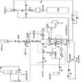
도 3은 본 발명의 예시적인 실시예에 따른 촉매 재생 장치의 개략 단면도이다.1 is a schematic view of a conventional catalyst regeneration apparatus.
2 is a schematic cross-sectional view of a dehydrogenation system including a catalyst regeneration apparatus according to an exemplary embodiment of the present invention.
3 is a schematic cross-sectional view of a catalyst regeneration apparatus according to an exemplary embodiment of the present invention.
이하에서 첨부 도면을 참조하여 본 발명의 실시예들에 대해서 더욱 상세하게 설명한다. 본 발명의 실시예는 예시로서 도시된 것이며, 첨부된 도면의 특징으로 제한되는 것은 아니다. 본 발명의 범주로부터 벗어나지 않는 한 다른 실시예들이 사용될 수 있으며, 구조적 또는 논리적 변화가 이루어질 수 있음을 이해할 것이다. 이하에서는, 유사한 구성 요소에 대해서는 유사한 도면 부호를 사용하여 설명한다. Hereinafter, embodiments of the present invention will be described in more detail with reference to the accompanying drawings. The embodiments of the present invention are shown by way of example and are not limited to the features of the accompanying drawings. It is to be understood that other embodiments may be utilized and structural or logical changes may be made without departing from the scope of the present invention. In the following, similar components will be described using similar reference numerals.
본원에서 "구역(ZONE)"이라는 용어는 하나 이상의 장치 또는 하부-구역을 포함하는 촉매 재생 장치 내의 특정 영역(area)을 의미하고, 본 발명에서 촉매 재생 장치의 본체(챔버)는 반응기로서 하나 이상의 구역들 또는 하부-구역들(sub-zones)을 포함할 수 있다. As used herein, the term " zone "refers to a specific area within a catalyst regenerator that includes at least one device or sub-zone, and the body (chamber) Zones or sub-zones. ≪ RTI ID = 0.0 >
도 2는 본 발명의 예시적인 실시예에 따른 촉매 재생 장치를 포함하는 탈수소화 시스템의 개략단면도이고, 도 3은 소비된 촉매 입자로부터 재생 촉매 입자를 형성하기 위한 촉매 재생 장치의 개략도이다. FIG. 2 is a schematic cross-sectional view of a dehydrogenation system including a catalyst regeneration apparatus according to an exemplary embodiment of the present invention, and FIG. 3 is a schematic view of a catalyst regeneration apparatus for forming regenerated catalyst particles from spent catalyst particles.
도 2를 참고하면, 탈수소화 반응기 등과 같은 촉매 반응에서 소비된 촉매는 촉매 수집기에서 수집된 후, 락 호퍼(lock hopper) 및 리프트 인게이져(lift engager)에 의해서 촉매 투입 라인(2)를 거쳐서 촉매 재생 장치에 공급된다.
2, catalysts consumed in a catalytic reaction such as a dehydrogenation reactor and the like are collected in a catalyst collector and then transported through a
도 3에 도시한 예시적인 실시예에서, 소비된 촉매 입자를 함유하는 스트림이 촉매 분리기(1)에 제공된다. 본 발명의 일 실시예의 방법에 의해 재생을 위해 촉매 재생 장치에 공급되는 소비된 촉매 입자는 스트림 소스에 따라 상이한 성분을 가질 수 있지만, 소비된 촉매 입자는 다공성이며, 촉매 활성도를 갖는 백금족 금속을 포함한다. In the exemplary embodiment shown in FIG. 3, a stream containing spent catalyst particles is provided to the catalyst separator 1. The consumed catalyst particles supplied to the catalyst regeneration apparatus for regeneration by the method of an embodiment of the present invention may have different components depending on the stream source but the spent catalyst particles are porous and contain a platinum group metal having catalytic activity do.
본 발명에서 소비된 촉매가 촉매 재생 장치의 연소 구역(10)에 투입되기 전에 연소 구역 상단에 일체로 형성된 촉매 분리기(1)에 의해서 촉매의 잔재 및 이물질을 분리해서 배출한 후 더스트 수집기(dust collector)에서 수집될 수 있고, 더스트 수집기에서 수집된 촉매는 소정의 처리를 거쳐 다시 촉매 재생 장치에 재투입될 수 있다.
Before the catalyst consumed in the present invention is injected into the
본 발명의 방법에서는 소비된 촉매 입자를 연소 구역(10)에 도입하고, 연소 가스를 연소 구역에 공급하여, 소비된 촉매 입자 상의 코크를 연소 가스를 사용하여 연소시키는 단계, 촉매 입자를 연소 구역으로부터 염소화 구역(20)으로 안내하여. 촉매 입자를 염소화하여 재생 촉매입자를 형성하는 단계 및 촉매 입자를 염소화 구역으로부터 건조 구역(30)으로 안내하여, 가열된 건조 가스를 건조 구역에 공급하여 촉매 입자를 건조시키는 단계를 거쳐 소비된 촉매를 재생함에 있어서, In the method of the present invention, the spent catalyst particles are introduced into the
염소화 구역(20)에 염소화 가스를 유입하는 단계와 상기 염소화 구역(20)에서 배출되는 가스에 새로 보급되는 염소화 가스를 추가하여, 열교환기(24)에 의해서 가열한 후 염소화 구역 유입 라인(21)을 거쳐서 다시 염소화 구역(20)으로 순환시키는 단계를 포함한다. The chlorination gas is introduced into the
상기 염소화 구역(20)에 공급되기 위해서 열교환기(24)에 의해서 가열된 염소화 가스의 일부는 냉각기(26)에 의해서 냉각된 후 라인(31)을 통해서 건조 구역(30)으로 이송될 수 있다. 이렇게 함으로써 비정상적인 코크 생성 시 염소화 구역의 온도를 조절하여 신속하게 공정을 정상화 할 수 있다.A portion of the chlorinated gas heated by the
본 발명의 방법에서 소비된 촉매 입자로부터의 코크의 제거는 촉매 재생 장치의 연소 구역(10)에서의 연소를 통해 실시된다. 도시한 바와 같이, 연소 구역(10)은 2개 이상의 연소 구역을 포함한다. 또한, 촉매 재생 장치는 소비된The removal of the coke from the spent catalyst particles in the process of the present invention is carried out through combustion in the
촉매 입자를 수용하기 위해 구역들 사이에서 연장되는 원통형 챔버(100)를 포함한다. 도시한 바와 같이, 소비된 촉매 입자의 스트림은 우선 연소 구역(10)으로 도입된다. 도시한 바와 같이, 촉매 재생 장치는 산소를 함유하는 연소 가스를 연소 구역(10)으로 공급하기 위한 적어도 하나의 연소 구역 유입 라인(12)를 구비하고, 연소 구역(10)에서의 코크의 연소를 제어하기 위해, 연소 가스 및 연소 구역(10) 내에서의 환경의 산소 함량이 엄격히 제어된다.And a cylindrical chamber (100) extending between the zones to receive the catalyst particles. As shown, the stream of spent catalyst particles is first introduced into the
또한, 코크화 또는 소비된 촉매 입자가 연소 구역(10)에 진입할 때, 고온이지만, 충분한 산소 함량은 소비된 촉매 입자 상의 잔류하는 통상적으로 내화성인 코크의 추가의 제어되는 연소를 가능하게 하여, 그 결과, 연소 배출 가스가 형성되고 연소 구역 배출 라인(11)을 통해서 촉매 재생 장치로부터 배출된다.
In addition, when the coked or spent catalyst particles enter the
연소 구역으로부터의 배출 가스 또는 그 일부는 연소 가스를 형성 또는 가열하는 데 사용될 수 있다. 연소 구역(10)에 공급할 산소 함유 가스를 형성하기 위해 연소 구역으로부터 배출된 배출 가스를 열교환기(15)에 의해 가열한 후, 산소 함유 가스와 혼합한다. 이어서 혼합된 가스를 냉각기(16)를 이용하여 외부 공기와의 열교환에 의해 냉각하고, 냉각된 산소 함유 가스와 혼합된 가스를 연소 구역 유입 라인(12)를 통해서 다시 연소 구역(10)으로 재투입한다. 여기서 냉각기(16)는 연소 구역의 온도 조절을 위한 기능을 수행하고, 열교환기(15)에 의해 연소 구역으로부터 배출된 배출 가스를 가열하는 이유는 재생기를 공정 O/H 이후 재가동 시 연소 구역의 온도를 승온하기 위하여 추가로 열을 공급해 주어야 하기 때문이다.
The exhaust gas or a portion thereof from the combustion zone can be used to form or heat the combustion gas. The exhaust gas discharged from the combustion zone to form an oxygen-containing gas to be supplied to the
한편, 상기 연소 구역 배출 라인(11)으로부터 배출된 기체 가운데 염소 가스는 송풍기(14)와 열교환기(15) 사이에서 분리되어, 열교환기(15)에 의한 가열 이전에 라인 40을 거쳐서 대기로 배기된다. 이렇게 함으로써 공정 에너지를 절감할 수 있다.On the other hand, the chlorine gas among the gases discharged from the combustion
또한 연소 구역(10)으로부터 배출되어 연소 구역으로 재투입되기 위해 냉각기(16)에 의해서 냉각 처리된 저온의 냉각 기체의 일부를 염소화 구역(20)에 주입되는 염소화 가스의 냉각에 이용할 수 있다. 즉, 냉각기(16)에 의해서 냉각된 냉각 기체는 라인 50을 거쳐서 냉각기(26)으로 전달되어 냉각기 26에서의 냉각에 활용될 수 있다. It is also possible to use a portion of the cold cooling gas cooled by the cooler 16 to exit the
소비된 촉매 입자는 코크 연소 후, 연소 구역(10)을 빠져나가기 때문에, 탈탄 촉매 입자라 한다. 탈탄 촉매 입자는 도관을 경유하여 연소구역(10)으로부터 염소화 구역(20)까지 촉매 재생 장치를 하향 통과하여 이동한다. 염소화 구역에서는 염소화 가스와 산소 함유 가스를 염소화 구역에 공급하여, 촉매 입자를 염소화 가스 및 산소 함유 가스와 접촉시키고, 백금족 금속을 재분산시키도록 촉매 입자를 염소화하여 재생 촉매 입자를 형성한다. The spent catalyst particles are called decarburized catalyst particles because they exit the
염소화 가스가 적어도 하나의 염소화 구역 유입 라인(21)를 통해 염소화 구역(20)으로 공급된다. 염소화 가스는 염소(Cl2)와 같은 염소 함유 가스와 공기와 같은 산소 함유 가스를 포함한다. 도 2 및 3에서는 단일의 유입 라인(21)가 염소 함유 가스와 산소 함유 가스의 조합된 스트림을 염소화 구역(20)에 공급하는 것으로 도시하고 있지만, 별도의 유입 라인이 가스들의 별도의 이송을 위해 마련될 수 있다. 염소화 구역(20) 내의 염소 함유 가스와 산소 함유 가스의 존재는 탈탄 촉매 입자의 염소화를 위해 주어진다. 염소화는 필수적인데, 그 이유는 탈탄 촉매 입자에 있는 백금족 금속이 처리 중에 직면하는 고온에서 응집을 경험하기 때문이다. 염소화 반응은 보다 양호한 촉매 활성도를 위해 탈탄 촉매 입자 상의 응집된 백금족 금속을 재분산시킨다.The chlorinated gas is supplied to the
염소화 구역(20)에는 하나 이상의 염소화제, 하나 이상의 산소 함유 가스 및 물이 공급된다. 염소화제는 염소, HCl 또는, 탄소수 4 미만 및 1 내지 6개의 염소 원자를 포함하는 염소화 탄화수소(예를 들면, 사염화탄소) 또는 이러한 재생 공정에서 염소를 방출하는 것으로 알려진 임의의 염소화제가 될 수 있다. The
염소화 구역(20)에서, 촉매는 투입된 가스와 접촉되며, 또한 건조 구역(30)으로부터의 가스와 접촉되고, 투입, 산소를 다시 충전하고, 건조 단계로부터의 소량의 물을 포함할 수 있다. 본 발명의 장치에서는 기존의 공지된 장치와 달리, 염소화 구역(20)에 염소 가스 주입 방식의 차이점은 염소화 구역의 염소화 가스 배출 라인(22)으로 배출된 가스를 송풍기(23)를 통하여 압축하고 열교환기(24)를 거치기 전에 별도 라인을 설치하여 이곳에 염소 가스를 주입하는 방식으로 구성된다. 이렇게 이중으로 염소 가스 주입 라인을 설치할 경우 별도 라인과 중심 라인의 관 직경 차이에 의한 유량 차이가 발생하게 설계가 가능하다. 이렇게 염소 주입 라인의 유속을 조절하는 이유는 염소 가스 주입 방식이 가는 모세관을 통하여 주입하는 방식이어서 공정 운전 중 염소 가스에 의한 손상이 쉽게 발생하여 가능한 적절한 모세관 크기를 확보해야 하는데 유량이 빠를수록 모세관이 더욱 가늘어져야 하기 때문이다.In the
본 발명의 촉매 재생 장치는 촉매의 유속을 제어하기 위해 상기 연소 구역(10) 및 염소화 구역(20)의 저부는 상기 반응기 챔버(100)의 외벽을 향해서 하방으로 테이퍼 형상으로 기울어져 있다. 염소화 구역(20) 내의 환경이 비교적 높은 산소 함량을 포함하기 때문에, 염소화 구역(20)에 진입하는 탈탄 촉매 입자는 임의의 코크가 없거나 거의 없어야만 한다. 염소화 후에 탈탄 촉매 입자는 염소화 촉매 입자로서 간주될 수 있다. 염소화 촉매 입자는 촉매 재생 장치에서 염소화 구역(20)으로부터 건조 구역(30)으로 안내된다. 가열된 건조 가스는 적어도 하나의 유입 라인(31)를 통해 건조 구역(30)에 공급된다. 건조 가스는 불활성 가스, 염소 함유 가스 및/또는 공기와 같은 산소 함유 가스를 포함할 수 있다. 건조 구역(30)에서, 건조 가스는 상류 반응에 기인하는 물을 제거하기 위해 염소화 촉매 입자를 통과하도록 송출된다.In the catalyst regenerating apparatus of the present invention, the bottoms of the
유입 라인(32)를 통해 공급되는 건조 가스는 염소 함유 가스와 산소 함유 가스를 포함할 수 있다. 건조 구역(30)이 염소화 구역(20)과 유체 연통되면, 염소화 구역(20)에 필요한 가스가 건조 구역(30)을 통해 유입 라인(32)에 의해 염소화 구역에 공급될 수 있다. 다만 연소 구역과 염소화 구역 사이에는 염소화 구역(20)의 가스를 연소 구역(10)에 있는 가스로부터 분리된 상태로 유지하기 위한 분리판이 형성된다. 염소화 구역(20)으로부터 배출된 가스는 라인(22)을 통해 촉매 재생 장치로부터 제거된 후에, 촉매 처리 장치를 거쳐 다시 염소화 구역(20)에 재주입된다. The dry gas supplied through the inlet line 32 may contain a chlorine-containing gas and an oxygen-containing gas. When the drying
도 3에 도시한 바와 같이, 재생 촉매 입자는 건조 구역(30)을 통과한 후에 촉매 재생 장치를 빠져나가고, 촉매 개질 시스템 또는 다른 촉매 시스템으로 다시 공급될 수도 있고, 연소 구역(10)에 공급되고 있는 소비된 촉매 입자의 스트림으로 재순환될 수도 있다.As shown in FIG. 3, the regenerated catalyst particles pass through the drying
도 3은 본 발명의 예시적인 실시예에 따라 촉매를 재생하기 위한 장치의 개략도이다. 도 3을 참조하면, 본 발명의 일 실시예의 촉매 재생 장치는 종방향으로 배치되는 하나 이상의 연소 구역을 포함하는 촉매 재생 장치로서, 상기 재생장치는 공급된 촉매로부터 촉매 잔재 및 오염물질을 제거하는 디스인게이징 호퍼(1); 및 상기 디스인게이징 호퍼와 일체로 형성되는 챔버(100)를 포함한다. 상기 챔버(100)는 하나 이상의 공급 가스 유입 라인과 재생된 촉매를 배출시키기 위한 촉매 배출 라인을 포함하고, 촉매는 이동상으로 연소 구역(Z1), 염소화 구역(Z2) 및 건조 구역(Z3)을 연속적으로 통과하도록 구성된다. 상기 연소 구역(Z1)은 2 이상의 방사형 연소 구역(10)으로 구성되고, 상기 염소화 구역(Z2)은 2 이상의 방사형 염소화 구역(20)으로 구성된다. 상기 염소화 구역(Z2)의 하단에는 염소화 가스 유입 라인(21)이 형성되고, 염소화 가스 배출 라인(22)이 상기 2 이상의 방사형 염소화 구역(Z2) 사이에 염소화 구역(20)과 일체로 형성된다.
3 is a schematic diagram of an apparatus for regenerating a catalyst according to an exemplary embodiment of the present invention. 3, a catalyst regeneration apparatus according to an embodiment of the present invention is a catalyst regeneration apparatus including at least one combustion zone arranged in the longitudinal direction, the regeneration apparatus comprising a catalyst bed for removing catalyst residues and contaminants from the supplied catalyst, An engaging hopper (1); And a
본 발명의 촉매 재생 장치는 연소 후, 탄소 함유 물질의 함량이 낮아진 탈탄 촉매는 도관을 통과하여 염소화 구역(20)에 도달한다. 그 후, 건조 구역(30)으로 흐르게 되어 촉매 배출 라인을 경유하여 본체에서 배출된다.
In the catalyst regenerating apparatus of the present invention, after burning, the decarburized catalyst having a lower content of carbon-containing material passes through the conduit to reach the chlorination zone (20). Then flows into the drying
상술한 본 발명의 상세한 설명에서는 적어도 하나의 예시적인 실시예를 제시하였지만, 다수의 변형이 존재함을 이해해야만 한다. 예시적인 실시예 또는 예시적인 실시예들은 단지 예일뿐이며, 본 발명의 범위, 적용성 또는 구성을 어떠한 방식으로든 제한하려는 의도는 없다는 것도 또한 이해해야만 한다.
While at least one exemplary embodiment has been presented in the foregoing detailed description of the invention, it should be understood that there are many variations. It is also to be understood that the exemplary embodiments or exemplary embodiments are merely examples, and are not intended to limit the scope, applicability or configuration of the invention in any way.
10 : 연소 구역
1: 디스인게이징 호퍼
11 : 연소 구역 배출 라인
12 : 연소 구역 유입 라인
14: 송풍기
15: 열교환기
16: 냉각기
20 : 염소화 구역
21 : 염소화 가스 유입 라인
22 : 염소화 가스 배출 라인
23, 25 : 송풍기
24: 열교환기
26: 냉각기
30 : 건조 구역
31 : 제1 건조 구역 유입 라인
32 : 제2 건조 구역 유입 라인
33: 열교환기 10: combustion zone 1: disengaging hopper
11: Combustion zone discharge line
12: combustion zone inflow line
14: blower 15: heat exchanger
16: cooler 20: chlorination zone
21: Chlorinated gas inflow line
22: Chlorinated gas discharge line
23, 25: blower 24: heat exchanger
26: cooler 30: drying zone
31: 1st drying zone inflow line
32: 2nd drying zone inflow line
33: heat exchanger
Claims (7)
염소화 구역에 염소화 가스를 유입하는 단계;
상기 염소화 구역에서 배출되는 가스에 새로 보급되는 염소화 가스를 추가하여, 가열한 후 다시 염소화 구역으로 순환시키는 단계를 포함하는 것을 특징으로 하는 촉매 재생 방법.
Introducing the spent catalyst particles into a combustion zone, supplying a combustion gas to the combustion zone, burning the coke on the spent catalyst particles with a combustion gas, and directing the catalyst particles from the combustion zone to the chlorination zone. A step of chlorinating the catalyst particles to form regenerated catalyst particles, and a step of guiding the catalyst particles from the chlorination zone to the drying zone and supplying the heated dry gas to a drying zone to dry the catalyst particles, The method
Introducing chlorinated gas into the chlorination zone;
Adding a freshly supplied chlorination gas to the gas discharged from the chlorination zone, and heating and then circulating the gas to the chlorination zone again.
The method of claim 1, comprising cooling a portion of the chlorinated gas supplied to the chlorination zone and transferring the cooled gas to a drying zone.
연소 구역으로부터 배출 가스를 배출하는 단계;
연소 구역에 공급할 산소 함유 가스를 형성하기 위해 연소 구역으로부터 배출된 배출 가스를 산소 함유 가스와 혼합하는 단계;
혼합된 가스를 외부 공기와의 열교환에 의해 냉각하는 단계; 및
냉각된 산소 함유 가스와 혼합된 가스를 다시 연소 구역으로 이송시키는 단계를 포함하는 것을 특징으로 하는 촉매 재생 방법.
The method of claim 1,
Exhausting the exhaust gas from the combustion zone;
Mixing the exhaust gas discharged from the combustion zone with an oxygen-containing gas to form an oxygen-containing gas to be supplied to the combustion zone;
Cooling the mixed gas by heat exchange with the outside air; And
And transferring the gas mixed with the cooled oxygen-containing gas to the combustion zone again.
The method of claim 3, wherein the method comprises separating chlorine gas from the gas exhausted from the combustion zone and exhausting it to the atmosphere before heating.
4. The method of claim 3, further comprising the step of using a portion of the chlorine gas cooled to be discharged from the combustion zone and re-entering the combustion zone for cooling the chlorinated gas injected into the chlorination zone Catalyst regeneration method.
소비된 촉매가 촉매 재생 장치의 연소 구역에 투입되기 전에 연소 구역 상단에 일체로 형성된 촉매 분리기에 의해서 촉매의 잔재 및 이물질을 분리해서 배출한 후 더스트 수집기에서 수집하는 단계를 추가로 포함하는 것을 특징으로 하는 촉매 재생 방법.
The method of claim 1,
Separating and discharging catalyst residues and foreign substances by a catalyst separator formed integrally with the upper end of the combustion zone before the spent catalyst is injected into the combustion zone of the catalyst regenerator, and collecting the collected catalyst in a dust collector / RTI >
염소화 가스와 산소 함유 가스를 염소화 구역에 공급하는 단계; 및
촉매 입자를 염소화 가스 및 산소 함유 가스와 접촉시키고, 백금족 금속을 재분산시키도록 촉매 입자를 염소화하여 재생 촉매 입자를 형성하는 단계를 포함하는 촉매 재생 방법.
The method of claim 1,
Supplying a chlorination gas and an oxygen-containing gas to the chlorination zone; And
Contacting the catalyst particles with a chlorinated gas and an oxygen-containing gas, and chlorinating the catalyst particles to redisperse the platinum group metal to form regenerated catalyst particles.
Priority Applications (1)
| Application Number | Priority Date | Filing Date | Title |
|---|---|---|---|
| KR1020140186297A KR101652599B1 (en) | 2014-12-22 | 2014-12-22 | Catalyst regeneration method |
Applications Claiming Priority (1)
| Application Number | Priority Date | Filing Date | Title |
|---|---|---|---|
| KR1020140186297A KR101652599B1 (en) | 2014-12-22 | 2014-12-22 | Catalyst regeneration method |
Publications (2)
| Publication Number | Publication Date |
|---|---|
| KR20160077342A true KR20160077342A (en) | 2016-07-04 |
| KR101652599B1 KR101652599B1 (en) | 2016-08-31 |
Family
ID=56500804
Family Applications (1)
| Application Number | Title | Priority Date | Filing Date |
|---|---|---|---|
| KR1020140186297A Active KR101652599B1 (en) | 2014-12-22 | 2014-12-22 | Catalyst regeneration method |
Country Status (1)
| Country | Link |
|---|---|
| KR (1) | KR101652599B1 (en) |
Cited By (1)
| Publication number | Priority date | Publication date | Assignee | Title |
|---|---|---|---|---|
| KR102124338B1 (en) * | 2019-03-11 | 2020-06-19 | 효성화학 주식회사 | Apparatus and method for regenerating catalyst |
Citations (2)
| Publication number | Priority date | Publication date | Assignee | Title |
|---|---|---|---|---|
| KR19980081375A (en) * | 1997-04-14 | 1998-11-25 | 알프레드엘마레 | Improved Methods and Units of Catalyst Regeneration for the Preparation or Modification of Aromatic Compounds |
| KR20140102245A (en) * | 2012-03-20 | 2014-08-21 | 유오피 엘엘씨 | Improved robustness of coke burning from catalyst for light paraffin dehydrogenation process |
-
2014
- 2014-12-22 KR KR1020140186297A patent/KR101652599B1/en active Active
Patent Citations (2)
| Publication number | Priority date | Publication date | Assignee | Title |
|---|---|---|---|---|
| KR19980081375A (en) * | 1997-04-14 | 1998-11-25 | 알프레드엘마레 | Improved Methods and Units of Catalyst Regeneration for the Preparation or Modification of Aromatic Compounds |
| KR20140102245A (en) * | 2012-03-20 | 2014-08-21 | 유오피 엘엘씨 | Improved robustness of coke burning from catalyst for light paraffin dehydrogenation process |
Cited By (1)
| Publication number | Priority date | Publication date | Assignee | Title |
|---|---|---|---|---|
| KR102124338B1 (en) * | 2019-03-11 | 2020-06-19 | 효성화학 주식회사 | Apparatus and method for regenerating catalyst |
Also Published As
| Publication number | Publication date |
|---|---|
| KR101652599B1 (en) | 2016-08-31 |
Similar Documents
| Publication | Publication Date | Title |
|---|---|---|
| KR0141481B1 (en) | Regeneration process of a catalyst for the reforming or for the production of aromatic hydrocarbons | |
| HU206643B (en) | Method for gas-circulating regenerating zone of movable-bed catalyzer | |
| KR101682734B1 (en) | Utilization of baffles in chlorination zone for continuous catalyst regeneration | |
| JP2937479B2 (en) | Method and apparatus for dehydrogenating alkanes | |
| CN103998129B (en) | There are multiple combustion zones of independent circulation circuit | |
| JPS5837019B2 (en) | How to get the job done | |
| CA2344015C (en) | A process for continuously regenerating catalyst particles | |
| CA2852512C (en) | Improved robustness of coke burning from catalyst for light paraffin dehydrogenation process | |
| US3843330A (en) | Regeneration apparatus | |
| US8993467B2 (en) | Catalyst regenerator process | |
| US9718047B2 (en) | Systems and methods for separating chlorine-containing species from aqueous solutions of chlorine-containing species | |
| CN118251270A (en) | Regeneration of dehydrogenation catalyst slip streams | |
| KR101652599B1 (en) | Catalyst regeneration method | |
| KR101652600B1 (en) | Catalyst regeneration apparatus | |
| US5277880A (en) | Catalyst regeneration apparatus with radial flow distribution | |
| US7585803B1 (en) | Catalyst regeneration method | |
| TW200838610A (en) | Process for regenerating catalyst for a hydrocarbon conversion zone | |
| KR101652598B1 (en) | Catalyst regeneration apparatus | |
| KR101652601B1 (en) | Catalyst regeneration apparatus | |
| RU2698876C2 (en) | Method of hydrogen chloride adsorption from regenerating outlet gas | |
| KR102124338B1 (en) | Apparatus and method for regenerating catalyst | |
| JP2008546682A (en) | Apparatus for producing vinyl chloride by pyrolysis of 1,2-dichloroethane and method for producing vinyl chloride using the same | |
| RU2564410C2 (en) | Method and device for regeneration of solid catalyst particles | |
| KR101652605B1 (en) | Apparatus and method for regenerating catalyst | |
| CN104437674B (en) | Regenerating method of catalytic conversion catalyst |
Legal Events
| Date | Code | Title | Description |
|---|---|---|---|
| PA0109 | Patent application |
St.27 status event code: A-0-1-A10-A12-nap-PA0109 |
|
| PA0201 | Request for examination |
St.27 status event code: A-1-2-D10-D11-exm-PA0201 |
|
| D13-X000 | Search requested |
St.27 status event code: A-1-2-D10-D13-srh-X000 |
|
| D14-X000 | Search report completed |
St.27 status event code: A-1-2-D10-D14-srh-X000 |
|
| PE0902 | Notice of grounds for rejection |
St.27 status event code: A-1-2-D10-D21-exm-PE0902 |
|
| P11-X000 | Amendment of application requested |
St.27 status event code: A-2-2-P10-P11-nap-X000 |
|
| P13-X000 | Application amended |
St.27 status event code: A-2-2-P10-P13-nap-X000 |
|
| PG1501 | Laying open of application |
St.27 status event code: A-1-1-Q10-Q12-nap-PG1501 |
|
| E701 | Decision to grant or registration of patent right | ||
| PE0701 | Decision of registration |
St.27 status event code: A-1-2-D10-D22-exm-PE0701 |
|
| GRNT | Written decision to grant | ||
| PR0701 | Registration of establishment |
St.27 status event code: A-2-4-F10-F11-exm-PR0701 |
|
| PR1002 | Payment of registration fee |
St.27 status event code: A-2-2-U10-U11-oth-PR1002 Fee payment year number: 1 |
|
| PG1601 | Publication of registration |
St.27 status event code: A-4-4-Q10-Q13-nap-PG1601 |
|
| PN2301 | Change of applicant |
St.27 status event code: A-5-5-R10-R11-asn-PN2301 |
|
| PN2301 | Change of applicant |
St.27 status event code: A-5-5-R10-R14-asn-PN2301 |
|
| FPAY | Annual fee payment |
Payment date: 20190711 Year of fee payment: 4 |
|
| PR1001 | Payment of annual fee |
St.27 status event code: A-4-4-U10-U11-oth-PR1001 Fee payment year number: 4 |
|
| PR1001 | Payment of annual fee |
St.27 status event code: A-4-4-U10-U11-oth-PR1001 Fee payment year number: 5 |
|
| PR1001 | Payment of annual fee |
St.27 status event code: A-4-4-U10-U11-oth-PR1001 Fee payment year number: 6 |
|
| PR1001 | Payment of annual fee |
St.27 status event code: A-4-4-U10-U11-oth-PR1001 Fee payment year number: 7 |
|
| PR1001 | Payment of annual fee |
St.27 status event code: A-4-4-U10-U11-oth-PR1001 Fee payment year number: 8 |
|
| PR1001 | Payment of annual fee |
St.27 status event code: A-4-4-U10-U11-oth-PR1001 Fee payment year number: 9 |
|
| PR1001 | Payment of annual fee |
St.27 status event code: A-4-4-U10-U11-oth-PR1001 Fee payment year number: 10 |
|
| U11 | Full renewal or maintenance fee paid |
Free format text: ST27 STATUS EVENT CODE: A-4-4-U10-U11-OTH-PR1001 (AS PROVIDED BY THE NATIONAL OFFICE) Year of fee payment: 10 |