KR20160077451A - Cell module for battery - Google Patents
Cell module for battery Download PDFInfo
- Publication number
- KR20160077451A KR20160077451A KR1020140187031A KR20140187031A KR20160077451A KR 20160077451 A KR20160077451 A KR 20160077451A KR 1020140187031 A KR1020140187031 A KR 1020140187031A KR 20140187031 A KR20140187031 A KR 20140187031A KR 20160077451 A KR20160077451 A KR 20160077451A
- Authority
- KR
- South Korea
- Prior art keywords
- wall surface
- reinforcing
- battery cell
- unit
- case
- Prior art date
- Legal status (The legal status is an assumption and is not a legal conclusion. Google has not performed a legal analysis and makes no representation as to the accuracy of the status listed.)
- Ceased
Links
Images

Classifications
-
- H—ELECTRICITY
- H01—ELECTRIC ELEMENTS
- H01M—PROCESSES OR MEANS, e.g. BATTERIES, FOR THE DIRECT CONVERSION OF CHEMICAL ENERGY INTO ELECTRICAL ENERGY
- H01M10/00—Secondary cells; Manufacture thereof
- H01M10/60—Heating or cooling; Temperature control
- H01M10/65—Means for temperature control structurally associated with the cells
- H01M10/655—Solid structures for heat exchange or heat conduction
- H01M10/6556—Solid parts with flow channel passages or pipes for heat exchange
-
- H—ELECTRICITY
- H01—ELECTRIC ELEMENTS
- H01M—PROCESSES OR MEANS, e.g. BATTERIES, FOR THE DIRECT CONVERSION OF CHEMICAL ENERGY INTO ELECTRICAL ENERGY
- H01M10/00—Secondary cells; Manufacture thereof
- H01M10/60—Heating or cooling; Temperature control
- H01M10/61—Types of temperature control
- H01M10/613—Cooling or keeping cold
-
- H—ELECTRICITY
- H01—ELECTRIC ELEMENTS
- H01M—PROCESSES OR MEANS, e.g. BATTERIES, FOR THE DIRECT CONVERSION OF CHEMICAL ENERGY INTO ELECTRICAL ENERGY
- H01M10/00—Secondary cells; Manufacture thereof
- H01M10/60—Heating or cooling; Temperature control
- H01M10/62—Heating or cooling; Temperature control specially adapted for specific applications
- H01M10/625—Vehicles
-
- H—ELECTRICITY
- H01—ELECTRIC ELEMENTS
- H01M—PROCESSES OR MEANS, e.g. BATTERIES, FOR THE DIRECT CONVERSION OF CHEMICAL ENERGY INTO ELECTRICAL ENERGY
- H01M10/00—Secondary cells; Manufacture thereof
- H01M10/60—Heating or cooling; Temperature control
- H01M10/65—Means for temperature control structurally associated with the cells
- H01M10/655—Solid structures for heat exchange or heat conduction
- H01M10/6551—Surfaces specially adapted for heat dissipation or radiation, e.g. fins or coatings
-
- H—ELECTRICITY
- H01—ELECTRIC ELEMENTS
- H01M—PROCESSES OR MEANS, e.g. BATTERIES, FOR THE DIRECT CONVERSION OF CHEMICAL ENERGY INTO ELECTRICAL ENERGY
- H01M50/00—Constructional details or processes of manufacture of the non-active parts of electrochemical cells other than fuel cells, e.g. hybrid cells
- H01M50/20—Mountings; Secondary casings or frames; Racks, modules or packs; Suspension devices; Shock absorbers; Transport or carrying devices; Holders
- H01M50/244—Secondary casings; Racks; Suspension devices; Carrying devices; Holders characterised by their mounting method
-
- H—ELECTRICITY
- H01—ELECTRIC ELEMENTS
- H01M—PROCESSES OR MEANS, e.g. BATTERIES, FOR THE DIRECT CONVERSION OF CHEMICAL ENERGY INTO ELECTRICAL ENERGY
- H01M50/00—Constructional details or processes of manufacture of the non-active parts of electrochemical cells other than fuel cells, e.g. hybrid cells
- H01M50/20—Mountings; Secondary casings or frames; Racks, modules or packs; Suspension devices; Shock absorbers; Transport or carrying devices; Holders
- H01M50/258—Modular batteries; Casings provided with means for assembling
-
- Y—GENERAL TAGGING OF NEW TECHNOLOGICAL DEVELOPMENTS; GENERAL TAGGING OF CROSS-SECTIONAL TECHNOLOGIES SPANNING OVER SEVERAL SECTIONS OF THE IPC; TECHNICAL SUBJECTS COVERED BY FORMER USPC CROSS-REFERENCE ART COLLECTIONS [XRACs] AND DIGESTS
- Y02—TECHNOLOGIES OR APPLICATIONS FOR MITIGATION OR ADAPTATION AGAINST CLIMATE CHANGE
- Y02E—REDUCTION OF GREENHOUSE GAS [GHG] EMISSIONS, RELATED TO ENERGY GENERATION, TRANSMISSION OR DISTRIBUTION
- Y02E60/00—Enabling technologies; Technologies with a potential or indirect contribution to GHG emissions mitigation
- Y02E60/10—Energy storage using batteries
Landscapes
- Chemical & Material Sciences (AREA)
- Chemical Kinetics & Catalysis (AREA)
- Electrochemistry (AREA)
- General Chemical & Material Sciences (AREA)
- Engineering & Computer Science (AREA)
- Manufacturing & Machinery (AREA)
- Battery Mounting, Suspending (AREA)
Abstract
본 발명은 배터리 셀 모듈에 관한 것으로, 본 발명에 따른 배터리 셀 모듈은 복수개의 벽면으로 형성되는 수용공간을 구비하는 케이스하우징과 상기 벽면에 각각 제공되는 보강유닛을 구비하는 배터리 셀 케이스 및 상기 배터리 셀 케이스에 수용되는 배터리 셀을 포함하여 구성되는 단위 모듈;을 복수개 포함하여 상기 단위 모듈이 상호 접촉되어 구성되되, 상기 단위 모듈의 접촉으로 냉각유로가 형성될 수 있다.The present invention relates to a battery cell module, and a battery cell module according to the present invention comprises a case housing having a housing space formed by a plurality of wall surfaces, a battery cell case having a reinforcing unit provided on the wall surface, The unit module includes a plurality of unit modules including a battery cell accommodated in the case. The unit modules are in contact with each other, and a cooling channel can be formed by contacting the unit modules.
Description
본 발명은 배터리 셀 모듈에 관한 것이다.
The present invention relates to a battery cell module.
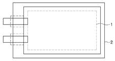
통상의 배터리 셀은 일측에 전극이 구비되며, 내부에 충전전류를 저장하고 있는 물질이다. 도 1에 보이듯이, 배터리 셀(1)은 안전, 기술상의 이유로 배터리 셀 케이스(2)에 수용되어 사용되는 것이 일반적이다.A conventional battery cell is a material having an electrode on one side and a charge current stored therein. As shown in FIG. 1, the
특히, 최근에는 환경보호 및 에너지 절감에 관한 관심이 높아지면서, 이와 같은 배터리 셀(1)을 포함하는 배터리 모듈을 장착한 전기자동차에 대한 연구가 활발하게 진행되고 있다. Particularly in recent years, interest in environmental protection and energy saving has increased, and studies on an electric vehicle equipped with a battery module including such a
전기자동차(EV; Electric vehicle)는 주로 배터리의 전원을 이용하여 AC 또는 DC 모터를 구동하여 동력을 얻는 자동차로서, 배터리에 충전된 전류를 통해 자동차를 움직이게 할 수 있다.An electric vehicle (EV) is an automobile that drives an AC or DC motor by using power from a battery and drives the automobile through a current charged in the battery.
이와 같은 전기자동차에 전류를 공급하는 배터리 모듈을 구성하는 경우, 이들의 기계적 체결 및 전기적 접속을 위해 일반적으로 많은 부재들이 필요하므로, 이러한 부재들을 조립하는 과정은 매우 복잡하다. When a battery module for supplying electric current to such an electric vehicle is constructed, since many members are generally required for mechanical fastening and electrical connection thereof, the process of assembling such members is very complicated.
더욱이, 기계적 체결 및 전기적 접속을 위한 다수의 부재들의 결합, 용접, 솔더링 등을 위한 공간이 요구되며, 그로 인해 시스템 전체의 크기는 커지게 될 뿐만 아니라 다수의 부재들이 들어가면서 배터리 모듈의 중량이 함께 증가하게 된다는 문제가 있다.In addition, space for the joining of a plurality of members for mechanical fastening and electrical connection, welding, soldering and the like is required, which not only increases the size of the entire system, but also increases the weight of the battery module There is a problem.
그런데, 이와 같은 중량의 증가는 갈수록 증대되고 있는 경량화와 고기능화에 대한 사용자의 요구에 상반된 것이며, 전기자동차의 경우 자동차의 연비가 나빠지게 되는 문제가 발생한다.However, such an increase in weight is contrary to a user's demand for increasing weight and functionality, which is increasingly increasing. In the case of an electric vehicle, the fuel efficiency of the vehicle is deteriorated.
게다가, 배터리 셀(1)의 내부에서는 다양한 용매를 사용하게 되는데, 이러한 용매는 고온에서 가스 등이 차오르는 일종의 부품현상인 스웰링(swelling)현상이 발생할 가능성이 내재되어 있다.In addition, various solvents are used in the interior of the
이러한 스웰링 현상은 배터리 모듈에서 전기적 쇼트현상을 야기시킬 수 있음은 물론, 부푼 상태에서 외부 충격이 가해지면 스파크 등이 발생하여 발화될 수 있어 더욱 위험할 수 있다.Such a swelling phenomenon may cause electrical short circuit in the battery module, and further, when an external shock is applied in a swollen state, sparks may be generated and may be ignited, which may be more dangerous.
특히, 고온에서 오랜 시간 동안 구동을 유지하여야 전기자동차의 경우에는 이러한 위험성은 더욱 높다고 할 수 있으며, 이차전지로 구성되는 배터리의 오동작은 이를 사용하는 사용자에게도 치명적인 위험요소가 될 수 있다.
Particularly, in case of an electric vehicle, the risk of the electric vehicle must be maintained for a long time at a high temperature, and the malfunction of the battery constituted by the secondary battery may be a serious risk to the user who uses the battery.
본 발명은 에너지 효율이 증가되고, 안전성의 확보가 가능한 배터리 셀 모듈을 제공하는 것을 일 목적으로 한다.An object of the present invention is to provide a battery cell module in which energy efficiency is increased and safety can be ensured.
구체적으로, 자체 중량 감소 및 냉각 효율의 증가를 통한 에너지 효율의 증가를 도모한다.Specifically, the energy efficiency is increased by decreasing its own weight and increasing cooling efficiency.
또한, 배터리 셀 케이스의 강성 및 내구성을 증대시켜, 스웰링 현상을 방지한다.
In addition, the stiffness and durability of the battery cell case are increased to prevent the swelling phenomenon.
본 발명은 배터리 셀 모듈에 관한 것으로, 본 발명에 따른 배터리 셀 모듈은 복수개의 벽면으로 형성되는 수용공간을 구비하는 케이스하우징과 상기 벽면에 각각 제공되는 보강유닛을 구비하는 배터리 셀 케이스 및 상기 배터리 셀 케이스에 수용되는 배터리 셀을 포함하여 구성되는 단위 모듈;을 복수개 포함하여 상기 단위 모듈이 상호 접촉되어 구성되되, 상기 단위 모듈의 접촉으로 냉각유로가 형성될 수 있다.The present invention relates to a battery cell module, and a battery cell module according to the present invention comprises a case housing having a housing space formed by a plurality of wall surfaces, a battery cell case having a reinforcing unit provided on the wall surface, The unit module includes a plurality of unit modules including a battery cell accommodated in the case. The unit modules are in contact with each other, and a cooling channel can be formed by contacting the unit modules.
바람직하게, 상기 보강유닛은, 상기 벽면 상에서 상기 벽면의 두께방향으로 돌출되어 형성되는 복수개의 보강돌부; 및 평탄하게 형성되고, 상기 벽면 상에서 상기 보강돌부의 사이사이에 배치되는복수개의 플랫부;를 포함할 수 있다.Preferably, the reinforcing unit includes: a plurality of reinforcing protrusions protruding in the thickness direction of the wall surface on the wall surface; And a plurality of flat portions formed between the reinforcing protrusions on the wall surface.
보다 바람직하게, 상기 냉각유로는, 일 벽면의 상기 보강돌부와 타 벽면의 상기 플랫부의 접촉으로 상기 단위 모듈 간의 접촉부에 형성되되, 상기 보강돌부의 외주와, 상기 플랫부의 외주에 의해 형성되는 틈새공간일 수 있다.More preferably, the cooling passage is formed in the contact portion between the unit modules by the contact between the reinforcing protrusion portion of the one wall surface and the flat portion of the other wall surface, and the outer circumference of the reinforcing protrusion portion and the gap portion formed by the outer circumference of the flat portion Lt; / RTI >
보다 바람직하게, 일 벽면의 상기 보강돌부와 타 벽면의 상기 보강돌부는 상호 엇갈리게 배치되어, 일 벽면의 상기 보강돌부는 타 벽면의 상기 플랫부에 밀착될 수 있다.More preferably, the reinforcing protrusions on one wall surface and the reinforcing protrusions on the other wall surface are staggered from each other, and the reinforcing protrusions on one wall surface can be brought into close contact with the flat portion of the other wall surface.
보다 바람직하게, 상기 보강돌부는, 상기 벽면 상에서 반원 형상으로 제공되되, 원호가 외측으로 돌출되게 제공되어, 상기 원호가 상기 플랫부에 밀착될 수 있다.More preferably, the reinforcing protrusion is provided on the wall surface in a semicircular shape, and the arc is provided so as to protrude outward, so that the arc can be brought into close contact with the flat portion.
보다 바람직하게, 상기 벽면은, 단일 판으로 구비되며, 상기 보강돌부는 상기 단일 판의 단면 형상을 변화시켜 형성될 수 있다.
More preferably, the wall surface is provided as a single plate, and the reinforcing protrusion can be formed by changing the sectional shape of the single plate.
본 발명에 의하면 배터리 셀 모듈의 에너지 효율이 증가되고, 안전성을 확보할 수 있다. According to the present invention, energy efficiency of the battery cell module is increased and safety can be ensured.
또한, 강성 및 내구성은 증대되면서도 경량화된 배터리 셀 모듈을 보다 저렴한 비용으로 구축할 수 있다.
In addition, it is possible to construct a battery cell module that is light in weight and at a low cost while increasing rigidity and durability.
도 1은 종래의 배터리 셀 모듈의 정면도이다.
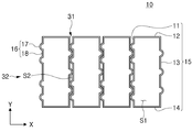
도 2a는 본 발명에 의한 배터리 셀 케이스의 평면도이다.
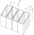
도 2b는 본 발명에 의한 배터리 셀 케이스의 사시도이다.
도 3은 본 발명에 의한 배터리 셀 모듈의 사시도이다.1 is a front view of a conventional battery cell module.
2A is a plan view of a battery cell case according to the present invention.
2B is a perspective view of a battery cell case according to the present invention.
3 is a perspective view of a battery cell module according to the present invention.
본 발명의 실시예에 관한 설명의 이해를 돕기 위하여 첨부된 도면에 동일한 부호로 기재된 요소는 동일한 요소이고, 각 실시예에서 동일한 작용을 하게 되는 구성요소 중 관련된 구성요소는 동일 또는 연장 선상의 숫자로 표기하였다.In order to facilitate an understanding of the description of the embodiments of the present invention, elements denoted by the same reference numerals in the accompanying drawings are the same element, and among the constituent elements that perform the same function in each embodiment, Respectively.
또한, 본 발명의 요지를 명확히 하기 위하여 종래의 기술에 의해 익히 알려진 요소와 기술에 대한 설명은 생략하며, 이하에서는, 첨부된 도면을 참고로 하여 본 발명에 관하여 상세히 설명하도록 한다.Further, in order to clarify the gist of the present invention, a description of elements and techniques well known in the prior art will be omitted, and the present invention will be described in detail with reference to the accompanying drawings.
다만, 본 발명의 사상은 제시되는 실시예에 제한되지 아니하고, 당업자에 의해 특정 구성요소가 추가, 변경, 삭제된 다른 형태로도 제안될 수 있을 것이나, 이 또한 본 발명과 동일한 사상의 범위 내에 포함됨을 밝혀 둔다.
It is to be understood, however, that the spirit and scope of the present invention are not limited to the embodiments shown, but may be suggested by those skilled in the art in other forms, additions, or alternatives, .
먼저, 본 발명의 바람직한 일 실시예에 따른 배터리 셀 모듈은 도 3에 보이는 것처럼, 배터리 셀 케이스(10)와 상기 배터리 셀 케이스(10)에 수용된 배터리 셀(20)을 포함하는 구성을 하나의 단위 모듈(30)로 한다.3, a battery cell module according to a preferred embodiment of the present invention includes a
그리고 상기 단위 모듈(30)이 복수개 구비되어, 나란하게 배열됨으로써 본 발명에 의한 배터리 셀 모듈(50)을 형성한다. 이때, 제1 단위 모듈(30a)에는 제2 단위 모듈(30b)이 접촉 또는 밀착되며, 상기 제1 단위 모듈과 상기 제2 단위 모듈에 의해 접촉부(31)가 형성된다.The plurality of
여기서, 상기 제1 단위 모듈 및 상기 제2 단위 모듈은 복수개의 단위 모듈(30)들 중 상호 접촉 또는 밀착되어 접촉부(31)를 형성하게 제공되는 단위 모듈들을 각각 지칭하는 것이다. 따라서, 이는 설명 상의 편의를 위한 명명일 뿐, 본 발명의 권리 범위를 한정하려는 의도가 아님을 밝혀 둔다.Here, the first unit module and the second unit module refer to the unit modules provided to form the
한편, 도 2a에 보이는 것처럼, 상기 배터리 셀 케이스(10)는 케이스하우징(15)과, 상기 케이스하우징에 구비되는 보강유닛(16)을 포함하여 구성될 수 있다. 2A, the
먼저, 상기 케이스하우징(15)은 복수개의 벽면의 결합으로 형성될 수 있다. 바람직하게, 복수개의 상기 벽면은 상기 케이스하우징(15)의 측벽을 형성하며, 각각 제1,2,3,4벽면(11,12,13,14)으로 제공될 수 있다.First, the
케이스하우징(15)의 측벽을 구성하는 상기 제1,2,3,4벽면에 더하여, 상면 또는 하면을 형성하는 추가적인 벽면(미도시)을 구비할 수도 있으나, 이는 본 발명에 의해 한정되는 것이 아니며 당업자에 의해 적절히 변경 적용 가능한 사항이다.In addition to the first, second, third, and fourth wall surfaces forming the side wall of the
상기 제1,2,3,4벽면(11,12,13,14)의 결합으로, 상기 벽면들의 내측에는 수용공간(S1)이 형성될 수 있다. 그리고 상기 수용공간(S1)에는 선술한 배터리 셀이 수용된다. The first, second, third, and
그러면, 상기 케이스하우징(15)의 복수개의 측벽들에 의해 감싸지는 배터리 셀은 외부 충격으로부터 보호될 수 있다. 또한, 상기 측벽들은 상기 배터리 셀의 내부 가스 발생에 의한 스웰링 현상으로부터 사용자 및 다른 부품들을 보호하는 효과가 있다.Then, the battery cell wrapped by the plurality of side walls of the
이와 같은 내부 가스 압력에 의한 스웰링은 정수압으로 상기 측벽들에 가해진다. 따라서, 상기 측벽들이 이 압력에 대하여 견딜 수 있도록, 상기 측벽들에는 보강유닛(16)이 구비될 수 있다.Such swelling by internal gas pressure is applied to the sidewalls under hydrostatic pressure. Thus, the sidewalls may be provided with a
보강유닛(16)은 제1,2,3,4벽면에 모두 형성될 수도 있고, 서로 대응되는 제1벽면(11)과 제3벽면(13)에만 구비될 수도 있으며, 이는, 사용자 및 사용환경에 의해 적절히 변경될 수 있는 사항이다.The
다만, 본 발명에서는 바람직하게 상기 제1벽면(11)과 상기 제3벽면(13)에 보강유닛이 구비된 경우를 예로 들어 설명하기로 한다.However, in the present invention, the reinforcing unit is preferably provided on the
보강유닛(16)은 상기 벽면들에서 각각 두께방향으로 돌출되어 형성되는 보강돌부(17) 및 평탄하게 형성되는 플랫부(18)를 포함한다. 특히, 상기 보강돌부 및 상기 플랫부는 복수개가 구비되되, 상기 벽면 상에서 순차적으로 배열된다.The reinforcing unit (16) includes a reinforcing protrusion (17) protruding in the thickness direction from the wall surfaces and a flat part (18) formed flat. In particular, a plurality of the reinforcing protrusions and the flat portions are provided, and are sequentially arranged on the wall surface.
또한, 상기 보강돌부(17)는 상기 벽면 상에서 반원 형상으로 제공되되, 원호가 외측으로 돌출되게 제공되어, 상기 원호가 상기 플랫부(18)에 밀착되게 제공된다. 다만, 상기 보강돌부(17) 및 상기 플랫부(18)의 형상은 당업자에 의해 변경 가능한 사항이며, 본 발명에 의해 한정되는 것은 아니다.The reinforcing
상기 보강돌부(17)를 플랫부(18)에 밀착시키면 두 개의 벽면이 서로 밀착되기 때문에, 내부 가스에 의한 압력을 지지할 수 있는 힘이 하나의 벽면일 때보다 증대되는 효과가 있다.Since the two wall surfaces are in close contact with each other when the reinforcing
즉, 일 벽면에 제공되는 상기 보강돌부(17)가 타 벽면에 제공되는 상기 플랫부(18)에 의해 지지되는 효과가 있는 것이다. 다시 말해, 도 2a에서 일 단위 모듈의 수용공간(S1)에서 보강돌부(17)의 외주를 향하여 X축 방향으로 작용하는 내부 압력을 상기 일 단위 모듈에 접촉하는 타 단위 모듈의 플랫부(18)가 함께 지지하여 주기 때문이다.That is, the reinforcing
따라서, 상기 보강돌부(17) 및 상기 플랫부(18)의 밀착으로 인하여 복수개의 벽면이 결합되는 효과가 있으므로, 종래의 벽면보다 그 두께를 얇게 구비하더라도 내부 압력을 지지하는 힘, 즉, 강성은 증가시킬 수 있는 효과가 있는 것이다. 이와 같은 면에서, 본 발명은 경량화를 추구할 수 있는 것이다.Therefore, since the reinforcing
또한, 도 2a에 보이는 것처럼, 제1벽면(11)의 경우 폭방향, 즉, Y축방향으로 보강돌부(17) 및 플랫부(18)가 복수개 구비된다. 그리고 벽면 상에서, 상기 보강돌부 및 상기 플랫부가 서로 번갈아가며 배치된다. 제3벽면(13)의 경우도 마찬가지로 상기 보강돌부 및 상기 플랫부가 서로 번갈아가며 배치된다. 2A, in the case of the
보강돌부(17)는 벽면의 두께방향으로, 즉, 수용공간(S1)의 반대방향으로 돌출되도록 구비될 수 있으며, 플랫부(18)는 평탄하게 구비될 수 있다. 이때, 바람직하게 상기 플랫부(18)의 길이는 상기 보강돌부(17)의 원호의 길이보다 길게 구비될 수 있는데, 이렇게 하면 후술되는 틈새공간(S2)의 형성이 용이한 효과가 있다.The reinforcing
또한 바람직하게, 상기 보강돌부는 상기 벽면에 일체형으로 제공되되, 상기 벽면의 단면 변화로 형성될 수 있다. 그러면, 상기 벽면의 단면이 변화되면서 강성을 확보할 수 있게 될 뿐만 아니라, 추가적인 부품의 결합없이도 강성을 확보할 수 있기 때문에 케이스하우징(10)의 경량화에 기여할 수 있는 효과가 있다.Also, preferably, the reinforcing protrusion is provided integrally with the wall surface, and may be formed by a change in cross-section of the wall surface. In this case, not only the rigidity can be ensured by changing the cross-section of the wall surface but also the rigidity can be ensured without the addition of additional parts, which contributes to weight reduction of the
더하여, 보강돌부(17)의 돌출된 형상이 평평하게 제공되는 플랫부(18)에 접촉되면, 틈새공간(S2)의 형성이 보다 용이하게 하는 효과도 있다.In addition, when the protruding shape of the reinforcing
이와 같은 보강돌부(17) 및 플랫부(18)는 각각의 단위 모듈(20)에서 서로 비대칭되게 구비될 수 있다.The reinforcing
즉, 상호 접촉부(31)를 형성하는 벽면들끼리는 상기 보강돌부와 상기 플랫부가 각각 Y축 방향으로 비대칭되게 배열하면, 상기 틈새공간(S2)을 용이하게 형성할 수 있다.That is, when the reinforcing protrusions and the flat portions are arranged asymmetrically in the Y-axis direction between the wall surfaces forming the
도 2a 및 도 2b에 보이는 것처럼, 상기 틈새공간(S2)은 냉각유로(32)로 제공될 수 있다. 즉, 냉각용 유체, 바람직하게는 공기가 통과할 수 있는 공간이 된다. 이렇게 하면, 상기 냉각유로(32)를 통해 열 방출이 용이하게 수행되고, 외기가 원활하게 순환될 수 있어, 냉각 효율이 증대되는 효과가 있다.As shown in FIGS. 2A and 2B, the clearance S2 may be provided in the
게다가, 별도의 냉각채널을 구비할 필요가 없어 경량화에 기여할 수 있고, 제조원가를 절감할 수 있는 효과가 있다.In addition, since it is not necessary to provide a separate cooling channel, it is possible to contribute to weight reduction and the manufacturing cost can be reduced.
뿐만 아니라, 상기 보강돌부(17)와 상기 플랫부(18)를 밀착시키면, 단일 벽면의 두께가 아니라 두 개의 벽면의 두께에 의해 지지되는 효과를 얻을 수 있다. 따라서, 배터리 셀 케이스(10) 내부에서 발생하는 압력을 버티고, 저항할 수 있는 힘이 하나의 벽면일 때보다 증가된다. 따라서, 스웰링 현상을 보다 효과적으로 방지할 수 있게 된다.In addition, when the reinforcing
따라서, 하나의 벽면의 두께를 종래의 절반까지 줄일 수 있어, 모듈의 경량화 및 제조원가 절감에 기여할 수 있다.Therefore, the thickness of one wall surface can be reduced to half of the conventional one, contributing to weight reduction of the module and manufacturing cost reduction.
특히, 상기 벽면의 재질을 강재(steel)로 구비하고, 보강유닛(16)을 탑재하여 상호 접촉부를 형성하도록 하면, 같은 강성을 갖는 강재 벽면을 기준으로 그 두께를 절반까지 줄일 수 있다.Particularly, when the material of the wall surface is made of steel and the
즉, 열전달 효과가 좋은 알루미늄(Al) 재질로 되어, 그 두께가 1mm에 해당하는 벽면과 동일한 강성과 열전달 효과를 내가 위해서 강재(steel)로 된 벽면은 그 두께가 0.7mm가 되어야 한다. 이러한 경우 알루미늄과 강재 벽면의 무게차이는 대략 2배 정도의 차이가 나게 된다. That is, it is made of aluminum (Al) material having a good heat transfer effect, and the wall made of steel should have a thickness of 0.7 mm in order to achieve the same rigidity and heat transfer effect as the wall having a thickness of 1 mm. In this case, the difference in weight between the aluminum and the steel wall surface is about twice the difference.
그런데 이러한 경우, 본 발명의 바람직한 일 실시예에 따른 보강유닛(16)을 구비하는 벽면에 의하면, 열전달 효과가 좋은 알루미늄(Al) 재질로 되어, 그 두께가 1mm에 해당하는 벽면과 동일한 강성과 열전달 효과를 내가 위해서 강재로 된 벽면의 두께를 0.35mm까지 줄일 수 있다. 그리하여, 모듈의 경량화 및 제조원가의 절감에 기여할 수 있게 되는 것이다.
In this case, according to the wall surface provided with the reinforcing
이상에서 설명한 사항은 본 발명의 일 실시예에 관하여 설명한 것이며, 본 발명의 권리범위는 이에 한정되는 것이 아니고, 청구범위에 기재된 본 발명의 기술적 사상을 벗어나지 않는 범위 내에서 다양한 수정 및 변형이 가능하다는 것은 당해 기술분야의 통상의 지식을 가진 자에게는 자명할 것이다.
It will be apparent to those skilled in the art that various modifications and variations can be made in the present invention without departing from the spirit or scope of the invention as defined in the appended claims. It will be apparent to those of ordinary skill in the art.
10 : 배터리 셀 케이스
20 : 배터리 셀
30 : 단위 모듈
50 : 배터리 셀 모듈10: battery cell case 20: battery cell
30: Unit module 50: Battery cell module
Claims (6)
상기 단위 모듈의 접촉으로 냉각유로가 형성되는 것을 특징으로 하는 배터리 셀 모듈.
A plurality of unit modules including a battery cell case having a case housing having a housing space formed by a plurality of wall surfaces and a reinforcing unit provided on the wall surface, and a battery cell accommodated in the battery cell case, Wherein the unit modules are configured to be in contact with each other,
And the cooling channel is formed by the contact of the unit module.
상기 보강유닛은,
상기 벽면 상에서 상기 벽면의 두께방향으로 돌출되어 형성되는 복수개의 보강돌부; 및
평탄하게 형성되고, 상기 벽면 상에서 상기 보강돌부의 사이사이에 배치되는복수개의 플랫부;
를 포함하는 것을 특징으로 하는 배터리 셀 모듈.
The method according to claim 1,
Wherein the reinforcing unit comprises:
A plurality of reinforcing protrusions protruding in a thickness direction of the wall surface on the wall surface; And
A plurality of flat portions formed flat and disposed between the reinforcing protrusions on the wall surface;
Wherein the battery cell module comprises:
상기 냉각유로는,
일 벽면의 상기 보강돌부와 타 벽면의 상기 플랫부의 접촉으로 상기 단위 모듈 간의 접촉부에 형성되되,
상기 보강돌부의 외주와, 상기 플랫부의 외주에 의해 형성되는 틈새공간인 것을 특징으로 하는 배터리 셀 모듈.
3. The method of claim 2,
The cooling channel
Wherein the reinforcing protrusion is formed on a contact portion between the unit modules by contact between the reinforcing protrusion on one wall surface and the flat portion on the other wall surface,
Wherein the battery cell module is a clearance space formed by an outer periphery of the reinforcing protrusion and an outer periphery of the flat portion.
일 벽면의 상기 보강돌부와 타 벽면의 상기 보강돌부는 상호 엇갈리게 배치되어, 일 벽면의 상기 보강돌부는 타 벽면의 상기 플랫부에 밀착되는 것을 특징으로 하는 배터리 셀 모듈.
The method of claim 3,
Wherein the reinforcing protrusions on the one wall surface and the reinforcing protrusions on the other wall surface are offset from each other so that the reinforcing protrusions on one wall surface are in close contact with the flat portion of the other wall surface.
상기 보강돌부는,
상기 벽면 상에서 반원 형상으로 제공되되, 원호가 외측으로 돌출되게 제공되어, 상기 원호가 상기 플랫부에 밀착되는 것을 특징으로 하는 배터리 셀 모듈.
5. The method of claim 4,
The reinforcing-
Wherein a circular arc is provided on the wall surface in a semicircular shape and an arc is provided to protrude outward so that the arc is brought into close contact with the flat portion.
상기 벽면은,
단일 판으로 구비되며, 상기 보강돌부는 상기 단일 판의 단면 형상을 변화시켜 형성되는 것을 특징으로 하는 배터리 셀 모듈.
6. The method of claim 5,
The wall surface
And the reinforcing protrusion is formed by changing the sectional shape of the single plate.
Priority Applications (1)
| Application Number | Priority Date | Filing Date | Title |
|---|---|---|---|
| KR1020140187031A KR20160077451A (en) | 2014-12-23 | 2014-12-23 | Cell module for battery |
Applications Claiming Priority (1)
| Application Number | Priority Date | Filing Date | Title |
|---|---|---|---|
| KR1020140187031A KR20160077451A (en) | 2014-12-23 | 2014-12-23 | Cell module for battery |
Publications (1)
| Publication Number | Publication Date |
|---|---|
| KR20160077451A true KR20160077451A (en) | 2016-07-04 |
Family
ID=56500900
Family Applications (1)
| Application Number | Title | Priority Date | Filing Date |
|---|---|---|---|
| KR1020140187031A Ceased KR20160077451A (en) | 2014-12-23 | 2014-12-23 | Cell module for battery |
Country Status (1)
| Country | Link |
|---|---|
| KR (1) | KR20160077451A (en) |
Cited By (3)
| Publication number | Priority date | Publication date | Assignee | Title |
|---|---|---|---|---|
| US10873114B2 (en) | 2016-12-23 | 2020-12-22 | Sk Innovation Co., Ltd. | Secondary battery module |
| US11114724B2 (en) | 2017-07-31 | 2021-09-07 | Lg Chem, Ltd. | Battery module, and battery pack and energy storage system including the same |
| KR102656319B1 (en) * | 2023-10-16 | 2024-04-12 | 주식회사 티엔피솔루션 | Packaging case for aqueous zinc ion battery |
-
2014
- 2014-12-23 KR KR1020140187031A patent/KR20160077451A/en not_active Ceased
Cited By (5)
| Publication number | Priority date | Publication date | Assignee | Title |
|---|---|---|---|---|
| US10873114B2 (en) | 2016-12-23 | 2020-12-22 | Sk Innovation Co., Ltd. | Secondary battery module |
| US11495848B2 (en) | 2016-12-23 | 2022-11-08 | Sk Innovation Co., Ltd. | Secondary battery module |
| US12021209B2 (en) | 2016-12-23 | 2024-06-25 | Sk On Co., Ltd. | Secondary battery module |
| US11114724B2 (en) | 2017-07-31 | 2021-09-07 | Lg Chem, Ltd. | Battery module, and battery pack and energy storage system including the same |
| KR102656319B1 (en) * | 2023-10-16 | 2024-04-12 | 주식회사 티엔피솔루션 | Packaging case for aqueous zinc ion battery |
Similar Documents
| Publication | Publication Date | Title |
|---|---|---|
| EP2658008B1 (en) | Battery Module | |
| JP5323782B2 (en) | Battery module and battery pack comprising a plurality of battery modules | |
| US10608219B2 (en) | Integrated cartridge and battery pack comprising same | |
| US10347885B2 (en) | Battery module | |
| CN108475742B (en) | Battery module including housing parts joined by snap-fit type connecting parts | |
| US20120100401A1 (en) | Battery pack | |
| EP3136468B1 (en) | Battery cell assembly for secondary battery, and secondary battery comprising same | |
| US20130252045A1 (en) | Battery module | |
| KR20180113906A (en) | Battery Pack with extendible battery module | |
| EP2808921A1 (en) | Battery module | |
| CN111937180B (en) | Battery modules including internal panels, battery packs including the battery modules and vehicles | |
| JP6636035B2 (en) | Battery compression inhibitor and battery module including the same | |
| WO2018012224A1 (en) | Battery module | |
| KR20150102632A (en) | Rechargeable battery pack | |
| JP6713052B2 (en) | Battery pack and automobile including the same | |
| KR20160107798A (en) | Battery Pack | |
| JP6465354B2 (en) | Power storage module | |
| KR20200077634A (en) | Battery module | |
| WO2018008532A1 (en) | Cell holder and battery pack | |
| KR20130030545A (en) | Battery unit cell comprised in inserted case and battery module assembled at least one thereof | |
| WO2013183559A1 (en) | Wiring module | |
| JP5602509B2 (en) | Power storage device | |
| JP2018063882A (en) | Battery pack and method of manufacturing the same | |
| JPWO2016208361A1 (en) | Power storage device | |
| JP6711234B2 (en) | Battery unit |
Legal Events
| Date | Code | Title | Description |
|---|---|---|---|
| A201 | Request for examination | ||
| PA0109 | Patent application |
St.27 status event code: A-0-1-A10-A12-nap-PA0109 |
|
| PA0201 | Request for examination |
St.27 status event code: A-1-2-D10-D11-exm-PA0201 |
|
| D13-X000 | Search requested |
St.27 status event code: A-1-2-D10-D13-srh-X000 |
|
| D14-X000 | Search report completed |
St.27 status event code: A-1-2-D10-D14-srh-X000 |
|
| E902 | Notification of reason for refusal | ||
| PE0902 | Notice of grounds for rejection |
St.27 status event code: A-1-2-D10-D21-exm-PE0902 |
|
| AMND | Amendment | ||
| E13-X000 | Pre-grant limitation requested |
St.27 status event code: A-2-3-E10-E13-lim-X000 |
|
| P11-X000 | Amendment of application requested |
St.27 status event code: A-2-2-P10-P11-nap-X000 |
|
| P13-X000 | Application amended |
St.27 status event code: A-2-2-P10-P13-nap-X000 |
|
| E601 | Decision to refuse application | ||
| PE0601 | Decision on rejection of patent |
St.27 status event code: N-2-6-B10-B15-exm-PE0601 |
|
| P11-X000 | Amendment of application requested |
St.27 status event code: A-2-2-P10-P11-nap-X000 |
|
| PG1501 | Laying open of application |
St.27 status event code: A-1-1-Q10-Q12-nap-PG1501 |
|
| E601 | Decision to refuse application | ||
| E801 | Decision on dismissal of amendment | ||
| PE0601 | Decision on rejection of patent |
St.27 status event code: N-2-6-B10-B15-exm-PE0601 |
|
| PE0801 | Dismissal of amendment |
St.27 status event code: A-2-2-P10-P12-nap-PE0801 |
|
| R18-X000 | Changes to party contact information recorded |
St.27 status event code: A-3-3-R10-R18-oth-X000 |
|
| R18-X000 | Changes to party contact information recorded |
St.27 status event code: A-3-3-R10-R18-oth-X000 |
|
| R18-X000 | Changes to party contact information recorded |
St.27 status event code: A-3-3-R10-R18-oth-X000 |
|
| P22-X000 | Classification modified |
St.27 status event code: A-2-2-P10-P22-nap-X000 |
|
| P22-X000 | Classification modified |
St.27 status event code: A-2-2-P10-P22-nap-X000 |
|
| P22-X000 | Classification modified |
St.27 status event code: A-2-2-P10-P22-nap-X000 |
|
| R18-X000 | Changes to party contact information recorded |
St.27 status event code: A-3-3-R10-R18-oth-X000 |
|
| P22-X000 | Classification modified |
St.27 status event code: A-2-2-P10-P22-nap-X000 |
|
| R18-X000 | Changes to party contact information recorded |
St.27 status event code: A-3-3-R10-R18-oth-X000 |
|
| R18-X000 | Changes to party contact information recorded |
St.27 status event code: A-3-3-R10-R18-oth-X000 |
|
| R18 | Changes to party contact information recorded |
Free format text: ST27 STATUS EVENT CODE: A-3-3-R10-R18-OTH-X000 (AS PROVIDED BY THE NATIONAL OFFICE) |
|
| R18-X000 | Changes to party contact information recorded |
St.27 status event code: A-3-3-R10-R18-oth-X000 |