KR20160077691A - Air hose reel device - Google Patents
Air hose reel device Download PDFInfo
- Publication number
- KR20160077691A KR20160077691A KR1020140187904A KR20140187904A KR20160077691A KR 20160077691 A KR20160077691 A KR 20160077691A KR 1020140187904 A KR1020140187904 A KR 1020140187904A KR 20140187904 A KR20140187904 A KR 20140187904A KR 20160077691 A KR20160077691 A KR 20160077691A
- Authority
- KR
- South Korea
- Prior art keywords
- air hose
- hose
- housing
- winding drum
- rotation
- Prior art date
- Legal status (The legal status is an assumption and is not a legal conclusion. Google has not performed a legal analysis and makes no representation as to the accuracy of the status listed.)
- Granted
Links
Images


Classifications
-
- B—PERFORMING OPERATIONS; TRANSPORTING
- B65—CONVEYING; PACKING; STORING; HANDLING THIN OR FILAMENTARY MATERIAL
- B65H—HANDLING THIN OR FILAMENTARY MATERIAL, e.g. SHEETS, WEBS, CABLES
- B65H75/00—Storing webs, tapes, or filamentary material, e.g. on reels
- B65H75/02—Cores, formers, supports, or holders for coiled, wound, or folded material, e.g. reels, spindles, bobbins, cop tubes, cans, mandrels or chucks
- B65H75/04—Kinds or types
- B65H75/08—Kinds or types of circular or polygonal cross-section
- B65H75/14—Kinds or types of circular or polygonal cross-section with two end flanges
-
- B—PERFORMING OPERATIONS; TRANSPORTING
- B65—CONVEYING; PACKING; STORING; HANDLING THIN OR FILAMENTARY MATERIAL
- B65H—HANDLING THIN OR FILAMENTARY MATERIAL, e.g. SHEETS, WEBS, CABLES
- B65H75/00—Storing webs, tapes, or filamentary material, e.g. on reels
- B65H75/02—Cores, formers, supports, or holders for coiled, wound, or folded material, e.g. reels, spindles, bobbins, cop tubes, cans, mandrels or chucks
- B65H75/18—Constructional details
- B65H75/26—Arrangements for preventing slipping of winding
-
- B—PERFORMING OPERATIONS; TRANSPORTING
- B65—CONVEYING; PACKING; STORING; HANDLING THIN OR FILAMENTARY MATERIAL
- B65H—HANDLING THIN OR FILAMENTARY MATERIAL, e.g. SHEETS, WEBS, CABLES
- B65H75/00—Storing webs, tapes, or filamentary material, e.g. on reels
- B65H75/02—Cores, formers, supports, or holders for coiled, wound, or folded material, e.g. reels, spindles, bobbins, cop tubes, cans, mandrels or chucks
- B65H75/18—Constructional details
- B65H75/30—Arrangements to facilitate driving or braking
-
- B—PERFORMING OPERATIONS; TRANSPORTING
- B65—CONVEYING; PACKING; STORING; HANDLING THIN OR FILAMENTARY MATERIAL
- B65H—HANDLING THIN OR FILAMENTARY MATERIAL, e.g. SHEETS, WEBS, CABLES
- B65H75/00—Storing webs, tapes, or filamentary material, e.g. on reels
- B65H75/02—Cores, formers, supports, or holders for coiled, wound, or folded material, e.g. reels, spindles, bobbins, cop tubes, cans, mandrels or chucks
- B65H75/34—Cores, formers, supports, or holders for coiled, wound, or folded material, e.g. reels, spindles, bobbins, cop tubes, cans, mandrels or chucks specially adapted or mounted for storing and repeatedly paying-out and re-storing lengths of material provided for particular purposes, e.g. anchored hoses, power cables
- B65H75/38—Cores, formers, supports, or holders for coiled, wound, or folded material, e.g. reels, spindles, bobbins, cop tubes, cans, mandrels or chucks specially adapted or mounted for storing and repeatedly paying-out and re-storing lengths of material provided for particular purposes, e.g. anchored hoses, power cables involving the use of a core or former internal to, and supporting, a stored package of material
- B65H75/40—Cores, formers, supports, or holders for coiled, wound, or folded material, e.g. reels, spindles, bobbins, cop tubes, cans, mandrels or chucks specially adapted or mounted for storing and repeatedly paying-out and re-storing lengths of material provided for particular purposes, e.g. anchored hoses, power cables involving the use of a core or former internal to, and supporting, a stored package of material mobile or transportable
-
- B—PERFORMING OPERATIONS; TRANSPORTING
- B65—CONVEYING; PACKING; STORING; HANDLING THIN OR FILAMENTARY MATERIAL
- B65H—HANDLING THIN OR FILAMENTARY MATERIAL, e.g. SHEETS, WEBS, CABLES
- B65H75/00—Storing webs, tapes, or filamentary material, e.g. on reels
- B65H75/02—Cores, formers, supports, or holders for coiled, wound, or folded material, e.g. reels, spindles, bobbins, cop tubes, cans, mandrels or chucks
- B65H75/34—Cores, formers, supports, or holders for coiled, wound, or folded material, e.g. reels, spindles, bobbins, cop tubes, cans, mandrels or chucks specially adapted or mounted for storing and repeatedly paying-out and re-storing lengths of material provided for particular purposes, e.g. anchored hoses, power cables
- B65H75/38—Cores, formers, supports, or holders for coiled, wound, or folded material, e.g. reels, spindles, bobbins, cop tubes, cans, mandrels or chucks specially adapted or mounted for storing and repeatedly paying-out and re-storing lengths of material provided for particular purposes, e.g. anchored hoses, power cables involving the use of a core or former internal to, and supporting, a stored package of material
- B65H75/44—Constructional details
- B65H75/4418—Arrangements for stopping winding or unwinding; Arrangements for releasing the stop means
- B65H75/4428—Arrangements for stopping winding or unwinding; Arrangements for releasing the stop means acting on the reel or on a reel blocking mechanism
- B65H75/4431—Manual stop or release button
Landscapes
- Storing, Repeated Paying-Out, And Re-Storing Of Elongated Articles (AREA)
Abstract
본 발명은 에어호스의 꼬임을 방지함은 물론 사용시 권취드럼의 회전을 구속하여 에어호스의 취급성을 향상시킬 수 있는 에어호스 수납장치를 개시한다. 개시된 에어호스 수납장치는 하우징과, 이 하우징에 회전가능하게 결합되며, 회전을 통해 에어호스를 권취하는 권취드럼과, 하우징과 결합되며 권취드럼이 회전함에 따라 에어호스의 일단부가 권취드럼의 회전중심에서 회전되도록 에어호스를 가이드하는 호스가이드유닛을 구비하는 것을 특징으로 한다.The present invention discloses an air hose housing apparatus capable of preventing twisting of an air hose and restraining rotation of a winding drum in use to improve handling of the air hose. The air hose storage device is characterized in that it comprises a housing, a winding drum rotatably coupled to the housing, for winding the air hose through rotation, and a housing coupled to the housing, wherein one end of the air hose, And a hose guide unit for guiding the air hose to be rotated.

Description
본 발명은 에어호스 수납장치에 관한 것으로서, 보다 상세하게는 에어호스의 꼬임을 방지함은 물론 사용시 권취드럼의 회전을 구속하여 에어호스의 취급성을 향상시킬 수 있도록 하는 에어호스 수납장치에 관한 것이다.
BACKGROUND OF THE INVENTION 1. Field of the Invention [0001] The present invention relates to an air hose housing apparatus, and more particularly, to an air hose housing apparatus that prevents twisting of an air hose and restrains rotation of a winding drum during use to improve handling properties of the air hose .
일반적으로, 요비선(Fish Tape, Wire Follow), 전선, 전화선, 통신선 등과 같이 다양한 종류의 케이블이 사용되며, 이와 같은 케이블은 보호관에 삽입되어 보호된다. 이중 요비선은 전화선이나 통신선 등과 같이 쉽게 변형되는 선을 원거리 이동시키기 위하여 사용하는 것으로, 피아노선이나 철선 등과 같이 휨이 적게 발생하는 선을 적어도 2개 이상을 꼬아서 제작하게 된다.Generally, various types of cables are used, such as fish tape, wire follow, wire, telephone line, communication line, etc., and such a cable is inserted and protected in a protective pipe. A double yaw line is used to move a line that is easily deformed such as a telephone line or a communication line, and is made by twisting at least two lines having less warpage such as a piano wire or a wire.
이러한 요비선은 탄성이 강해 잘 휘어지지 않을 뿐만 아니라, 한번 절곡되면 절곡된 부위를 원래상태로 펴서 복원시키기가 어려워 보관시 별도의 보관장치를 사용하게 된다. 통상의 요비선 보관장치는 커버유닛에 회전가능하게 결합되는 수납유닛에 요비선을 권취하여 보관하게 된다.Such a yaw line is not only not bent well due to its elasticity but also it is difficult to restore the folded portion to its original state once it is bent, so that a separate storage device is used for storage. In a conventional raviolet ray storage device, a rib line is wound around a storage unit rotatably coupled to a cover unit and stored.
한편, 산업현장에서 컴프레서를 사용할 때에도 원거리까지 컴프레서의 압축공기를 공급하기 위하여 에어호스가 사용되며, 에어호스를 권취기에 감아서 사용하게 된다.On the other hand, when using a compressor in an industrial field, an air hose is used to supply the compressed air of the compressor to a long distance, and the air hose is wound around a winder to be used.
그런데, 상기와 같은 종래의 에어호스 권취기는 고정형으로 제공되어 사용이 불편할 뿐만 아니라, 이동이나 보관 중에 수납유닛의 회전으로 에어호스가 풀리게 되는 문제점이 발생하게 된다.However, the conventional air hose winder as described above is provided in a fixed form, which is inconvenient to use, and there is a problem that the air hose is loosened by rotation of the storage unit during movement or storage.
따라서, 이를 개선할 필요성이 요청된다.Therefore, there is a need to improve this.
상기와 같은 종래기술로 대한민국 등록특허공보 제10-1155371호(등록일:2012년06월05일)에는 "에어호스 수납장치"가 개시되어 있고, 등록실용신안공보 제20-0393187호(등록일:2005년08월10일)에는 "에어 호스 권취기"가 개시되어 있다.
An air hose accommodating device is disclosed in Korean Patent Registration No. 10-1155371 (registered on Jun. 05, 2012) by the above-described conventional technique, and a registration hose 20-0393187 &Quot; Air hose winding machine "
본 발명은 상기와 같은 필요성에 의해 창출된 것으로서, 에어호스의 꼬임을 방지함은 물론 사용시 권취드럼의 회전을 구속하여 에어호스의 취급성을 향상시킬 수 있는 에어호스 수납장치를 제공하는데 그 목적이 있다.
The present invention has been made in view of the above-mentioned need, and it is an object of the present invention to provide an air hose housing apparatus capable of preventing twisting of an air hose and restraining rotation of a winding drum in use to improve handling properties of the air hose. have.
상기와 같은 목적을 달성하기 위하여 본 발명에 따른 에어호스 수납장치는, 하우징; 상기 하우징에 회전가능하게 결합되며, 회전을 통해 에어호스를 권취하는 권취드럼; 및 상기 하우징과 결합되며, 상기 권취드럼이 회전함에 따라 상기 에어호스의 일단부가 상기 권취드럼의 회전중심에서 회전되도록 상기 에어호스를 가이드하는 호스가이드유닛을 포함하는 것을 특징으로 한다.According to an aspect of the present invention, there is provided an air hose storage device comprising: a housing; A winding drum rotatably coupled to the housing and winding the air hose through rotation; And a hose guide unit coupled to the housing and guiding the air hose so that one end of the air hose is rotated at the rotation center of the wind-up drum as the winding drum rotates.
또한, 상기 호스가이드유닛은, 상기 에어호스가 상기 권취드럼의 회전중심을 통해 상기 하우징으로 외부로 노출되도록 상기 권취드럼의 회전중심에 설치되는 것을 특징으로 한다.Further, the hose guide unit is installed at the center of rotation of the winding drum so that the air hose is exposed to the outside through the rotation center of the winding drum.
또한, 상기 호스가이드유닛은, 상기 권취드럼과 함께 회전하도록 상기 권취드럼에 결합되며, 상기 에어호스를 상기 하우징의 외측으로 가이드하는 호스꼬임방지부를 포함하는 것을 특징으로 한다.The hose guide unit may include a hose anti-twist portion coupled to the winding drum to rotate together with the winding drum, and configured to guide the air hose to the outside of the housing.
또한, 상기 호스가이드유닛은, 상기 권취드럼 및 상기 호스꼬임방지부가 회전가능하게 결합되도록 상기 하우징에 결합되는 회전지지부를 더 포함하는 것을 특징으로 한다.The hose guide unit may further include a rotation support portion coupled to the housing such that the winding drum and the hose-keeper portion are rotatably coupled.
또한, 상기 호스꼬임방지부는, 상기 회전지지부에 회전가능하게 삽입되며, 내부로 상기 에어호스가 관통하는 가이드관; 이 가이드관의 이탈을 방지하는 스냅링; 및 상기 가이드관에 결합되어 상기 에어호스의 이탈을 방지하는 호스이탈방지캡을 포함하는 것을 특징으로 한다.Further, the hose kink prevention portion may include a guide pipe rotatably inserted into the rotation support portion and passing through the air hose into the inside thereof; A snap ring for preventing the guide tube from departing; And a hose separation prevention cap coupled to the guide pipe to prevent the air hose from being separated from the hose.
또한, 상기 회전지지부는, 외면 및 내면에 상기 권취드럼 및 호스꼬임방지부가 각각 회전가능하게 결합되는 회전지지관; 상기 회전지지관이 결합되도록 상기 하우징에 구비되는 지지블록; 및 상기 회전지지관에 결합되어 상기 회전드럼에 고정되는 드럼이탈방지부재를 포함하는 것을 특징으로 한다.Also, the rotation support portion may include: a rotation support pipe having the outer surface and the inner surface thereof rotatably coupled to the winding drum and the hose-keeper portion; A support block provided in the housing to couple the rotation support pipe; And a drum release preventing member coupled to the rotary support tube and fixed to the rotary drum.
또한, 상기 에어호스 수납장치는, 상기 하우징에 구비되어 상기 권취드럼의 회전을 선택적으로 구속하는 스톱퍼를 더 포함하는 것을 특징으로 한다.
The air hose storage device further includes a stopper provided in the housing for selectively restricting rotation of the winding drum.
이상에서 설명한 바와 같이, 본 발명에 따른 에어호스 수납장치는 종래 발명과 달리 에어호스를 사용할 때 권취드럼의 회전을 구속시킬 수 있으므로, 에어호스를 안정되게 사용할 수 있다.As described above, the air hose storage device according to the present invention can restrain the rotation of the winding drum when the air hose is used, unlike the prior art, so that the air hose can be stably used.
또한, 본 발명에 의하면, 에어호스를 이동이 가능한 하우징에 권취하여 보관하므로, 이동이나 보관이 용이하고, 운반 중에 에어호스가 풀리는 것을 방지하여 에어호스의 파손을 방지할 수 있다.
Further, according to the present invention, since the air hose is wound and housed in a movable housing, it can be easily moved and stored, and the air hose can be prevented from being unraveled during transportation, so that breakage of the air hose can be prevented.
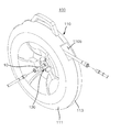
도 1은 본 발명의 일 실시예에 따른 에어호스 수납장치를 도시한 정면사시도이다.
도 2는 본 발명의 일 실시예에 따른 에어호스 수납장치를 도시한 배면사시도이다.
도 3은 본 발명의 일 실시예에 따른 에어호스 수납장치의 요부확대 단면도이다.
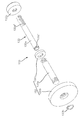
도 4는 본 발명의 일 실시예에 따른 호스가이드유닛을 도시한 분해사시도이다.
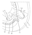
도 5는 본 발명의 일 실시예에 따른 스톱퍼의 결합구조를 도시한 요부확대 사시도이다.1 is a front perspective view showing an air hose housing apparatus according to an embodiment of the present invention.
2 is a rear perspective view showing an air hose housing apparatus according to an embodiment of the present invention.
3 is an enlarged cross-sectional view of a main part of an air hose housing apparatus according to an embodiment of the present invention.
4 is an exploded perspective view illustrating a hose guide unit according to an embodiment of the present invention.
FIG. 5 is an enlarged perspective view showing a coupling structure of a stopper according to an embodiment of the present invention. FIG.
이하, 첨부된 도면들을 참조하여 본 발명에 따른 에어호스 수납장치의 바람직한 실시예를 설명한다. 이 과정에서 도면에 도시된 선들의 두께나 구성요소의 크기 등은 설명의 명료성과 편의상 과장되게 도시되어 있을 수 있다. 또한, 후술되는 용어들은 본 발명에서의 기능을 고려하여 정의된 용어들로서 이는 사용자, 운용자의 의도 또는 관례에 따라 달라질 수 있다. 그러므로, 이러한 용어들에 대한 정의는 본 명세서 전반에 걸친 내용을 토대로 내려져야 할 것이다.DESCRIPTION OF THE PREFERRED EMBODIMENTS Hereinafter, preferred embodiments of an air hose housing apparatus according to the present invention will be described with reference to the accompanying drawings. In this process, the thicknesses of the lines and the sizes of the components shown in the drawings may be exaggerated for clarity and convenience of explanation. In addition, the terms described below are defined in consideration of the functions of the present invention, which may vary depending on the intention or custom of the user, the operator. Therefore, definitions of these terms should be made based on the contents throughout this specification.
도 1은 본 발명의 일 실시예에 따른 에어호스 수납장치를 도시한 정면사시도이고, 도 2는 본 발명의 일 실시예에 따른 에어호스 수납장치를 도시한 배면사시도이고, 도 3은 본 발명의 일 실시예에 따른 에어호스 수납장치의 요부확대 단면도이다.FIG. 1 is a front perspective view showing an air hose housing apparatus according to an embodiment of the present invention, FIG. 2 is a rear perspective view showing an air hose housing apparatus according to an embodiment of the present invention, and FIG. Fig. 3 is an enlarged cross-sectional view of a main portion of an air hose housing apparatus according to an embodiment.
또한, 도 4는 본 발명의 일 실시예에 따른 에어가이드유닛을 도시한 분해사시도이고, 도 5는 본 발명의 일 실시예에 따른 스톱퍼의 결합구조를 도시한 요부확대 사시도이다.FIG. 4 is an exploded perspective view illustrating an air guide unit according to an embodiment of the present invention, and FIG. 5 is an enlarged perspective view illustrating a coupling structure of a stopper according to an embodiment of the present invention.
도 1 내지 도 5에 도시된 바와 같이, 본 실시예에 따른 에어호스 수납장치(100)는 일단부이 공급측(컴프레서, 콘센트)에 연결되고, 타단부에 사용측(전동공구)이 연결되는 전선이나 에어호스 등을 권취하게 된다. 이러한, 에어호스 수납장치(100)는 사용, 취급 및 운반 등을 용이하게 할 수 있도록 에어호스(10)가 권취 또는 풀리게 된다.1 to 5, the air
더하여, 본 실시예에 따른 에어호스 수납장치(100)는 에어호스(10)를 풀어서 사용할 때 에어호스(10)의 인출된 상태를 안정되게 고정시킬 수 있도록 하여 에어호스(10)의 취급성을 더욱 향상시킬 수 있다.In addition, the air
이를 위하여, 본 실시예에 따른 에어호스 수납장치(100)는 설치공간부를 가지는 하우징(110)과, 이 하우징(110)에 회전가능하게 결합되어 회전을 통해 에어호스(10)를 권취 또는 인출시키는 권취드럼(120)과, 이 에어호스(10)의 일단부를 권취드럼(120)의 회전중심을 통해 컴프레서에 연결하기 위한 호스가이드유닛(130)과, 권취드럼(120)의 회전을 선택적으로 구속하는 스톱퍼(140)를 포함한다.For this purpose, the air
이와 같은 에어호스 수납장치(100)는 에어호스(10)를 풀거나 권취할 때 컴프레서와 연결된 에어호스(10)의 일단부가 호스가이드유닛(130)에 의해 꼬이는 것이 방지된다.The air
하우징(110)은 제1케이스(111)와 제2케이스(113)가 결합되어 형성되며, 상단부에 파지를 위한 운반손잡이(110a)가 구비된다. 또한, 하우징(110)은 측면에 에어호스(10)의 인출 및 권취를 위한 출입구(110b)를 구비한다.The
더하여, 하우징(110)은 제1케이스(111)에 호스가이드유닛(130)이 결합되고, 제2케이스(113)에 스톱퍼(140)가 결합되며, 호스가이드유닛(130)에 권취드럼(120)이 회전가능하게 결합된다. 이때, 제1케이스(111)에는 호스가이드유닛(130)를 설치하기 위한 가이드유닛결합구멍(111a)이 형성되고, 제2케이스(113)에는 스톱퍼(140)가 외부로 돌출하는 것이 방지되도록 장착함몰부(113a)가 형성된다. 장착함몰부(113a)에는 스톱퍼(140)의 용이한 조작을 위하여 가이드홈(113b)이 연통되게 형성된다.The
권취드럼(120)은 호스가이드유닛(130)에 회전가능하게 결합되도록 중앙부에 베어링(B)이 구비되며, 회전을 통해 에어호스(10)가 권취 또는 풀리도록 원통형으로 형성된다. 또한, 권취드럼(120)은 사용자가 파지하여 회전시킬 수 있도록 회전손잡이(121)를 구비한다. 이때, 회전손잡이(121)는 미사용시 권취드럼(120)의 내측으로 삽입되도록 권취드럼(120)에 힌지결합된다.The winding
이러한, 권취드럼(120)은 하우징(110)의 설치공간부에 설치되어 하우징(110)의 내부에 완전하게 삽입되도록 호스가이드유닛(130)에 결합되며, 스톱퍼(140)에 의해 그 회전이 선택적으로 구속된다. 더하여, 권취드럼(120)은 스톱퍼(140)가 선택적으로 삽입되어 걸리도록 걸림홈부(123)가 테두리부를 따라 이격되게 형성된다.The
호스가이드유닛(130)은 에어호스(10)의 일단부가 권취드럼(120)의 회전중심에서 회전되도록 에어호스(10)를 하우징(110)의 외측으로 가이드한다. 이러한, 호스가이드유닛(130)은 에어호스(10)가 권취드럼(120)의 회전중심을 통해 제1케이스(111)의 외부로 노출되도록 제1케이스(111)에 설치되어 권취드럼(120)의 회전을 지지함과 동시에 에어호스(10)를 회전시킨다.The
이를 위하여, 본 실시예에 따른 호스가이드유닛(130)은 권취드럼(120)이 회전가능하게 결합되도록 제1케이스(111)의 가이드유닛결합구멍(111a)에 설치되는 회전지지부(131)와, 에어호스(10)를 가이드하도록 회전지지부(131)에 회전가능하게 설치되는 호스꼬임방지부(133)를 포함한다.To this end, the
회전지지부(131)는 권취드럼(120) 및 호스꼬임방지부(133)가 회전가능하게 결합되도록 제1케이스(111)에 결합된다. 구체적으로, 회전지지부(131)는 가이드유닛결합구멍(111a)에 삽입되는 회전지지관(131a)과, 이 회전지지관(131a)을 제1케이스(111)에 고정하기 위한 지지블록(131b)과, 회전지지관(131a)에 권취드럼(120)을 고정하기 위한 드럼이탈방지부재(131c)를 포함한다.The
회전지지관(131a)은 지지블록(131b) 및 드럼이탈방지부재(131c)와 용이하게 결합되도록 양단부 외면에 수나사부가 형성된다. 이러한, 회전지지관(131a)은 외면에 권취드럼(120)의 베어링(B)이 축결합되고, 내면에 호스꼬임방지부(133)가 회전가능하게 삽입된다.The
지지블록(131b)은 스크루를 통해 제1케이스(111)에 고정되며, 권취드럼(120)과 결합되는 회전지지관(131a)을 안정되게 지지한다. 이러한, 지지블록(131b)은 회전지지관(131a)을 용이하게 결합할 수 있도록 중앙부에 암나사홈이 형성된다.The
드럼이탈방지부재(131c)는 링형상을 가지며, 제1케이스(111)의 베어링(B) 내륜을 지지하도록 회전지지관(131a)에 결합된다.The drum
호스꼬임방지부(133)는 에어호스(10)가 권취 또는 풀림에 따라 회전하는 권취드럼(120)과 함께 회전하도록 회전지지관(131a)에 회전가능하게 결합되며, 에어호스(10)를 제1케이스(111)의 외측으로 가이드한다.The hose
이러한, 호스꼬임방지부(133)는 회전지지관(131a)에 회전가능하게 삽입되며, 내부로 에어호스(10)가 관통하는 가이드관(133a)과, 이 가이드관(133a)의 이탈을 방지하기 위한 스냅링(133b)과, 가이드관(133a)에 결합되어 에어호스(10)의 이탈을 방지하는 호스이탈방지캡(133c)을 포함한다.The
가이드관(133a)은 일단부 및 타단부가 회전지지관(131a)의 양단부로 노출하도록 회전지지관(131a)에 삽입되며, 일단부에 스냅링(133b)을 결합하기 위한 걸림홈(133a')이 형성되고, 타단부에 호스이탈방지캡(133c)을 결합하기 위한 수나사부가 형성된다. 이러한, 가이드관(133a)은 권취드럼(120)의 회전중심에서 노출되는 에어호스(10)가 권취드럼(120)의 테두리부측으로 만곡지게 절곡되도록 가이드장홀(133a")이 형성된다. 가이드장홀(133a")은 권취드럼(120)의 권취부로 삽입되는 에어호스(10)가 급격하게 절곡되는 것을 방지함은 물론 권취드럼(120)의 외측으로 노출되는 부위를 감소시킨다.The
호스이탈방지캡(133c)은 가이드장홀(133a")로 노출되는 에어호스(10)를 고정하여 가이드관(133a)에서 이탈되는 것을 방지함은 물론 권취드럼(120)의 테두리부측으로 가이드한다. 이러한, 호스이탈방지캡(133c)은 가이드관(133a)의 나사부에 결합되도록 중앙부에 암나사홈이 형성된다.The hose
한편, 본 실시예에 따른 스톱퍼(140)는 사용자가 에어호스(10)를 사용할 때 권취드럼(120)이 회전하는 것을 방지하여 작업성을 향상시키게 된다. 이러한, 스톱퍼(140)는 제2케이스(113)의 장착함몰부(113a)에 스크루를 통해 결합되며, 권취드럼(120)의 회전을 선택적으로 구속하도록 걸림홈부(123)에 선택적으로 걸리게 된다. 이때, 스톱퍼(140)는 걸림홈부(123)에 선택적으로 삽입되는 걸림핀(141)을 구비하며, 사용자가 걸림핀(141)을 용이하게 조작할 수 있도록 걸림핀(141)의 일단부가 가이드홈(113b)을 통해 장착함몰부(113a)의 외부로 노출된다.Meanwhile, the
또한, 에어호스(10)는 컴프레서 및 전동공구와 연결되도록 양단부에 커플링이 각각 구비된다.Further, the
상기와 같은 구성을 갖는 본 발명의 일 실시예에 따른 에어호스 수납장치의 작용을 설명한다.The operation of the air hose housing apparatus according to an embodiment of the present invention having the above-described structure will be described.
먼저, 스톱퍼(140)를 작동시켜 걸림핀(141)을 걸림홈부(123)에서 이격시킨다. 이런 상태에서 사용자가 에어호스(10)를 잡아당기거나, 회전손잡이(121)를 회전시키면 권취드럼(120)이 회전하면서 권취드럼(120)에 권취되어 있던 에어호스(10)가 풀리거나 또는 풀려있던 에어호스(10)가 권취된다.First, the
그리고, 권취드럼(120)이 회전하면, 가이드관(133a)을 통해 하우징(110)의 외부로 노출된 에어호스(10)가 가이드관(133a)과 함께 회전하게 된다. 이로 인하여, 권취드럼(120)의 회전에 의해 에어호스(10)가 꼬이는 것이 방지된다. When the winding
즉, 컴프레서와 연결되는 에어호스(10)의 일단부가 권취드럼(120)의 회전중심에서 회전하는 가이드관(133a)에 삽입되므로, 권취드럼(120)이 회전할 때 권취드럼(120)의 회전중심에서 회전하게 된다.That is, since one end of the
또한, 에어호스(10)의 인출이 완료되면 에어호스(10)를 사용하는 동안 에어호스(10)에 작용하는 힘에 의해 권취드럼(120)이 회전하여 에어호스(10)가 권취 또는 인출되는 것이 방지되도록 스톱퍼(140)를 작동하여 권취드럼(120)의 회전을 구속한다. 이를 통해 작업중 에어호스(10)가 권취 또는 인출되지 않으므로 작업성을 보다 향상시킬 수 있다.When the drawing of the
본 발명은 도면에 도시된 실시예를 참고로 하여 설명되었으나, 이는 예시적인 것에 불과하며, 당해 기술이 속하는 분야에서 통상의 지식을 가진 자라면 이로부터 다양한 변형 및 균등한 타 실시예가 가능하다는 점을 이해할 것이다.While the present invention has been particularly shown and described with reference to exemplary embodiments thereof, it will be understood by those of ordinary skill in the art that various changes in form and details may be made therein without departing from the spirit and scope of the invention as defined by the appended claims. I will understand.
따라서, 본 발명의 진정한 기술적 보호범위는 특허청구범위에 의해서 정하여져야 할 것이다.
Accordingly, the true scope of protection of the present invention should be defined by the claims.
100 : 에어호스 수납장치
110 : 하우징
111 : 제1케이스
113 : 제2케이스
120 : 권취드럼
121 : 회전손잡이
123 : 걸림홈부
130 : 호스가이드유닛
131 : 회전지지부
133 : 호스꼬임방지부
140 : 스톱퍼100: air hose housing device 110: housing
111: first case 113: second case
120: winding drum 121: rotary knob
123: engagement groove portion 130: hose guide unit
131: rotation support part 133: hose kink prevention part
140: Stopper
Claims (7)
상기 하우징에 회전가능하게 결합되며, 회전을 통해 에어호스를 권취하는 권취드럼; 및
상기 하우징과 결합되며, 상기 권취드럼이 회전함에 따라 상기 에어호스의 일단부가 상기 권취드럼의 회전중심에서 회전되도록 상기 에어호스를 가이드하는 호스가이드유닛;
을 포함하는 것을 특징으로 하는 에어호스 수납장치.housing;
A winding drum rotatably coupled to the housing and winding the air hose through rotation; And
A hose guide unit coupled to the housing and guiding the air hose such that one end of the air hose is rotated at the rotation center of the wind-up drum as the winding drum rotates;
Wherein the air hose accommodating device comprises:
상기 호스가이드유닛은, 상기 에어호스가 상기 권취드럼의 회전중심을 통해 상기 하우징의 외부로 노출되도록 상기 권취드럼의 회전중심에 설치되는 것을 특징으로 하는 에어호스 수납장치.The method according to claim 1,
Wherein the hose guide unit is installed at the rotation center of the winding drum so that the air hose is exposed to the outside of the housing through the rotation center of the winding drum.
상기 호스가이드유닛은, 상기 권취드럼과 함께 회전하며, 상기 에어호스를 상기 하우징으로 외측으로 가이드하는 호스꼬임방지부를 포함하는 것을 특징으로 하는 에어호스 수납장치.3. The method according to claim 1 or 2,
Wherein the hose guide unit includes a hose anti-twist portion that rotates together with the winding drum and guides the air hose outwardly to the housing.
상기 호스가이드유닛은, 상기 권취드럼 및 상기 호스꼬임방지부가 회전가능하게 결합되도록 상기 하우징에 결합되는 회전지지부를 더 포함하는 것을 특징으로 하는 에어호스 수납장치.The method of claim 3,
Wherein the hose guide unit further comprises a rotation support portion coupled to the housing so that the winding drum and the hose keeper portion are rotatably coupled.
상기 회전지지부에 회전가능하게 삽입되며, 내부로 상기 에어호스가 관통하는 가이드관; 및
상기 가이드관에 결합되어 상기 에어호스의 이탈을 방지하는 호스이탈방지캡;
을 포함하는 것을 특징으로 하는 에어호스 수납장치.The hose guiding device according to claim 4, wherein the hose-
A guide pipe rotatably inserted into the rotation support portion and passing through the air hose into the guide pipe; And
A hose separation prevention cap coupled to the guide tube to prevent the air hose from being separated from the hose;
Wherein the air hose accommodating device comprises:
상기 권취드럼 및 상기 호스꼬임방지부가 외면 및 내면에 각각 회전가능하게 결합되는 회전지지관; 및
상기 회전지지관이 결합되도록 상기 하우징에 구비되는 지지블록;
를 포함하는 것을 특징으로 하는 에어호스 수납장치.[5] The apparatus according to claim 4,
A rotation support pipe rotatably coupled to the outer surface and the inner surface of the winding drum and the hose-keeper portion; And
A support block provided in the housing to couple the rotation support pipe;
And an air hose accommodating portion for accommodating the air hose.
상기 하우징에 구비되어 상기 권취드럼의 회전을 선택적으로 구속하는 스톱퍼를 더 포함하는 것을 특징으로 하는 에어호스 수납장치.The method according to claim 1,
Further comprising a stopper provided on the housing for selectively restricting rotation of the winding drum.
Priority Applications (1)
| Application Number | Priority Date | Filing Date | Title |
|---|---|---|---|
| KR1020140187904A KR101680654B1 (en) | 2014-12-24 | 2014-12-24 | Air hose reel device |
Applications Claiming Priority (1)
| Application Number | Priority Date | Filing Date | Title |
|---|---|---|---|
| KR1020140187904A KR101680654B1 (en) | 2014-12-24 | 2014-12-24 | Air hose reel device |
Publications (2)
| Publication Number | Publication Date |
|---|---|
| KR20160077691A true KR20160077691A (en) | 2016-07-04 |
| KR101680654B1 KR101680654B1 (en) | 2016-11-29 |
Family
ID=56501107
Family Applications (1)
| Application Number | Title | Priority Date | Filing Date |
|---|---|---|---|
| KR1020140187904A Active KR101680654B1 (en) | 2014-12-24 | 2014-12-24 | Air hose reel device |
Country Status (1)
| Country | Link |
|---|---|
| KR (1) | KR101680654B1 (en) |
Cited By (1)
| Publication number | Priority date | Publication date | Assignee | Title |
|---|---|---|---|---|
| US12535153B2 (en) | 2023-06-01 | 2026-01-27 | Samsung Electronics Co., Ltd. | Apparatus for folding tube |
Family Cites Families (1)
| Publication number | Priority date | Publication date | Assignee | Title |
|---|---|---|---|---|
| KR200391396Y1 (en) | 2005-03-14 | 2005-08-05 | 주식회사 오피시스 | a jump code reel |
-
2014
- 2014-12-24 KR KR1020140187904A patent/KR101680654B1/en active Active
Cited By (1)
| Publication number | Priority date | Publication date | Assignee | Title |
|---|---|---|---|---|
| US12535153B2 (en) | 2023-06-01 | 2026-01-27 | Samsung Electronics Co., Ltd. | Apparatus for folding tube |
Also Published As
| Publication number | Publication date |
|---|---|
| KR101680654B1 (en) | 2016-11-29 |
Similar Documents
| Publication | Publication Date | Title |
|---|---|---|
| US8251212B2 (en) | Small hand carried barrel-shaped case for the storage and dispensing of spools of electrical wire | |
| US5833165A (en) | Retraction reel for keys and the like | |
| CN101004345B (en) | Tape | |
| US6056226A (en) | Caddy for electric extension cords | |
| US20120312651A1 (en) | Rewindable Electrical Cable Extension Device | |
| US10230200B1 (en) | Cord retractor | |
| JP2009527430A (en) | Reel comprising a housing having a triangular opening for containing a linear substance | |
| US20140311849A1 (en) | Cable housing apparatus | |
| KR101680654B1 (en) | Air hose reel device | |
| CN112438655B (en) | Cleaning device for a cable | |
| US20080023358A1 (en) | Bucket and cord | |
| US20070210131A1 (en) | Enclosed spool | |
| US9295244B2 (en) | Fishing reel with fishhook hanger | |
| KR101790071B1 (en) | Cable rack | |
| KR20160077690A (en) | Cable rack | |
| KR101155371B1 (en) | Cable rack | |
| CN209906105U (en) | A wire take-up device and a wire take-up type power adapter device | |
| US10196232B2 (en) | Hose assembly | |
| KR101563353B1 (en) | Cable bag | |
| KR200211681Y1 (en) | cable reel for supplying electric power | |
| JP2017199889A (en) | Code case | |
| KR101608785B1 (en) | Electric wrie windding drvige | |
| US11365086B2 (en) | Device used to release, retract and store a cable or cable-like structure | |
| CN106743999A (en) | Spooler | |
| KR101560749B1 (en) | Withdrawals and the cleanup of the extension easily accommodated through extension |
Legal Events
| Date | Code | Title | Description |
|---|---|---|---|
| A201 | Request for examination | ||
| PA0109 | Patent application |
Patent event code: PA01091R01D Comment text: Patent Application Patent event date: 20141224 |
|
| PA0201 | Request for examination | ||
| E902 | Notification of reason for refusal | ||
| PE0902 | Notice of grounds for rejection |
Comment text: Notification of reason for refusal Patent event date: 20160204 Patent event code: PE09021S01D |
|
| PG1501 | Laying open of application | ||
| E701 | Decision to grant or registration of patent right | ||
| PE0701 | Decision of registration |
Patent event code: PE07011S01D Comment text: Decision to Grant Registration Patent event date: 20160822 |
|
| GRNT | Written decision to grant | ||
| PR0701 | Registration of establishment |
Comment text: Registration of Establishment Patent event date: 20161123 Patent event code: PR07011E01D |
|
| PR1002 | Payment of registration fee |
Payment date: 20161124 End annual number: 3 Start annual number: 1 |
|
| PG1601 | Publication of registration | ||
| FPAY | Annual fee payment |
Payment date: 20191122 Year of fee payment: 4 |
|
| PR1001 | Payment of annual fee |
Payment date: 20191122 Start annual number: 4 End annual number: 4 |
|
| FPAY | Annual fee payment |
Payment date: 20201019 Year of fee payment: 5 |
|
| PR1001 | Payment of annual fee |
Payment date: 20201019 Start annual number: 5 End annual number: 5 |
|
| FPAY | Annual fee payment |
Payment date: 20210927 Year of fee payment: 6 |
|
| PR1001 | Payment of annual fee |
Payment date: 20210927 Start annual number: 6 End annual number: 6 |
|
| FPAY | Annual fee payment |
Payment date: 20220915 Year of fee payment: 7 |
|
| PR1001 | Payment of annual fee |
Payment date: 20220915 Start annual number: 7 End annual number: 7 |
|
| PR1001 | Payment of annual fee |
Payment date: 20230912 Start annual number: 8 End annual number: 8 |
|
| PR1001 | Payment of annual fee |
Payment date: 20240913 Start annual number: 9 End annual number: 9 |