KR20160077996A - Agricultural vehicle - Google Patents
Agricultural vehicle Download PDFInfo
- Publication number
- KR20160077996A KR20160077996A KR1020140188594A KR20140188594A KR20160077996A KR 20160077996 A KR20160077996 A KR 20160077996A KR 1020140188594 A KR1020140188594 A KR 1020140188594A KR 20140188594 A KR20140188594 A KR 20140188594A KR 20160077996 A KR20160077996 A KR 20160077996A
- Authority
- KR
- South Korea
- Prior art keywords
- shroud
- mounting bracket
- radiator
- engine
- water tank
- Prior art date
- Legal status (The legal status is an assumption and is not a legal conclusion. Google has not performed a legal analysis and makes no representation as to the accuracy of the status listed.)
- Granted
Links
Images



Classifications
-
- B—PERFORMING OPERATIONS; TRANSPORTING
- B60—VEHICLES IN GENERAL
- B60K—ARRANGEMENT OR MOUNTING OF PROPULSION UNITS OR OF TRANSMISSIONS IN VEHICLES; ARRANGEMENT OR MOUNTING OF PLURAL DIVERSE PRIME-MOVERS IN VEHICLES; AUXILIARY DRIVES FOR VEHICLES; INSTRUMENTATION OR DASHBOARDS FOR VEHICLES; ARRANGEMENTS IN CONNECTION WITH COOLING, AIR INTAKE, GAS EXHAUST OR FUEL SUPPLY OF PROPULSION UNITS IN VEHICLES
- B60K11/00—Arrangement in connection with cooling of propulsion units
- B60K11/02—Arrangement in connection with cooling of propulsion units with liquid cooling
-
- Y—GENERAL TAGGING OF NEW TECHNOLOGICAL DEVELOPMENTS; GENERAL TAGGING OF CROSS-SECTIONAL TECHNOLOGIES SPANNING OVER SEVERAL SECTIONS OF THE IPC; TECHNICAL SUBJECTS COVERED BY FORMER USPC CROSS-REFERENCE ART COLLECTIONS [XRACs] AND DIGESTS
- Y02—TECHNOLOGIES OR APPLICATIONS FOR MITIGATION OR ADAPTATION AGAINST CLIMATE CHANGE
- Y02T—CLIMATE CHANGE MITIGATION TECHNOLOGIES RELATED TO TRANSPORTATION
- Y02T10/00—Road transport of goods or passengers
- Y02T10/60—Other road transportation technologies with climate change mitigation effect
- Y02T10/70—Energy storage systems for electromobility, e.g. batteries
Landscapes
- Engineering & Computer Science (AREA)
- Chemical & Material Sciences (AREA)
- Combustion & Propulsion (AREA)
- Transportation (AREA)
- Mechanical Engineering (AREA)
- Cooling, Air Intake And Gas Exhaust, And Fuel Tank Arrangements In Propulsion Units (AREA)
Abstract
농업용 작업차가 개시된다. 본 발명에 따른 농업용 작업차는, 운전석 전방의 보닛으로 둘러싸인 엔진 룸에 라디에이터가 설치되고, 라디에이터의 외면부를 둘러싸는 슈라우드를 구비하며, 슈라우드 외부 일 측면에 장착 브라켓이 설치되고, 장착 브라켓을 통해 라디에이터와 엔진 사이의 엔진 룸 상부 측방에 보조 물탱크가 설치됨으로써, 보조 물탱크 취부를 위해 별도로 공간을 확보하거나, 이를 위해 주변 부품의 레이아웃을 변경하지 않아도 된다.The agricultural work vehicle is started. The agricultural work vehicle according to the present invention is characterized in that a radiator is installed in an engine room surrounded by a bonnet in front of a driver's seat and a shroud surrounding an outer surface portion of the radiator and a mounting bracket is installed on one side of the shroud, The auxiliary water tank is provided on the upper side of the engine room between the engines so that space for securing the auxiliary water tank can be ensured without changing the layout of peripheral parts.
Description
본 발명은 농업용 작업차에 관한 것으로, 특히 운전석 전방의 보닛으로 둘러싸인 엔진 룸의 적소에 라디에이터의 냉각수 오버 플로우 분을 저장하는 보조 물탱크를 구비한 농업용 작업차에 관한 것이다.
BACKGROUND OF THE
농작업차 중 경전용으로 잘 알려진 트랙터(Tractor)는, 조향륜이 되는 전륜과 전륜에 비해 직경이 큰 구동 측 후륜을 포함하는 차륜형으로 구성된다. A tractor well known for light driving in an agricultural work vehicle is constituted by a wheel type including a front wheel serving as a steering wheel and a driving side rear wheel having a diameter larger than that of the front wheel.
전륜과 후륜 사이의 기체에는 기체 조작을 위한 운전석이 배치되며, 운전석 전방에는 보닛으로 둘러싸여 엔진 룸을 구성한다. 그리고 엔진 룸 내에는 엔진을 비롯해 수많은 전기 및 기계부품 등이 취부되어 원동부를 구성한다.A driver's seat for gas operation is arranged on the body between the front and rear wheels, and the engine room is surrounded by the bonnet on the front of the driver's seat. Inside the engine compartment, a number of electrical and mechanical parts, including an engine, are mounted to form the driving section.
트랙터의 사양이나 크기에 따라 차이는 있으나, 엔진 룸 공간은 보닛이 둘러싸는 영역에 국한된다. 따라서 제한된 공간에 수많은 부품들을 실장하려면 무엇보다 효율적인 부품 배치가 중요하다.The engine room space is limited to the area surrounded by the bonnet, although it depends on the specifications and size of the tractor. Therefore, the most efficient placement of components is important for mounting a large number of parts in a limited space.
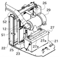
도 1에는 종래기술에 따른 농업용 작업차의 원동부 구조가 도시되어 있다.Fig. 1 shows a driving part structure of an agricultural work vehicle according to the prior art.
도 1의 도시와 같이, 종래 농업용 작업차의 원동부는 엔진(도시 생략)과 엔진 전방의 라디에이터(22)를 포함한다. 라디에이터(22)의 전방 상측에 에어클리너(29)가 구비되고, 에어클리너(29)의 하방에 배터리(27)가 탑재된다.As shown in Fig. 1, the driving unit of the conventional agricultural work vehicle includes an engine (not shown) and a
또한, 라디에이터(22)의 일측 전면에 연료 쿨러(12)와 오일 쿨러(25)가 구비되고, 오일 쿨러(25)의 전방으로 콘덴서(23)가 자리한다. 그리고 라디에이터(22)와 상기 에어클리너(29) 사이의 라디에이터(22) 전면 측부에는 서브 탱크(26)가 배치된다. A
이때, 상기 서브 탱크(26)는 라디에이터(22)의 오버 플로우 분의 냉각수를 저장하며, 라디에이터(22) 지지대(부호 생략)에 지지 브라켓(부호 생략)을 연결하여 고정시킨다. At this time, the
그러나 라디에이터(22)와 에어클리너(29) 사이의 비좁은 공간에 서브 탱크(26)가 배치됨으로써 유지 보수에 어려움이 수반되고, 라디에이터(22)와 에어클리너(26) 사이에 서브탱크(26)가 자리할 수 있을 정도의 여유공간을 확보해야 하는 설계 상의 어려움이 있다. However, since the
즉 종래에는 서브탱크(26) 배치를 위해 라디에이터(22) 전방의 에어클리너(29)를 비롯해 주변의 다른 부품들의 레이아웃(ray-out)을 바꾸거나 엔진 룸 공간을 증대시켜야 하므로, 작업차의 전체적인 외형이 달라지거나 크기를 키워야 하는 문제가 있다.
In other words, conventionally, in order to arrange the
본 발명이 해결하고자 하는 과제는, 엔진 룸 내 여유공간을 유효하게 활용하여 별도의 공간 확보나 주변 부품의 레이아웃 변경 없이도 엔진 룸 적소에 보조 물탱크를 취부할 수 있는 농업용 작업차를 제공하고자 하는 것이다.
An object of the present invention is to provide an agricultural work vehicle capable of effectively utilizing an available space in an engine room and securing a separate space or mounting an auxiliary water tank at a proper position in an engine room without changing the layout of surrounding components .
과제의 해결 수단으로서 본 발명은, 운전석 전방의 보닛으로 둘러싸인 엔진 룸에 라디에이터가 설치되고, 상기 라디에이터의 외면부를 둘러싸는 슈라우드를 구비하며, 상기 슈라우드 외부 일 측면에 장착 브라켓이 설치되며, 상기 장착 브라켓을 통해 라디에이터와 엔진 사이의 엔진 룸 상부 측방에 보조 물탱크가 설치된 것을 특징으로 하는 농업용 작업차를 제공한다.A mounting bracket is installed on one side of the outer side of the shroud, and the mounting bracket is mounted on an outer side of the shroud, Wherein an auxiliary water tank is installed on an upper side of the engine room between the radiator and the engine through the auxiliary water tank.
본 발명에서 상기 슈라우드 외부 일 측면에 브라켓 결합부가 구성되고, 상기 브라켓 결합부에 상기 장착 브라켓의 일부가 구속되고 다른 일부는 상기 슈라우드 일면에 볼트 고정될 수 있다.In the present invention, a bracket coupling part is formed on one side of the shroud, a part of the mounting bracket is constrained to the bracket coupling part, and the other part is bolted to one side of the shroud.
본 발명에서 상기 브라켓 결합부는, 상기 슈라우드 일 측면 상부에 슈라우드의 전후 두께 방향으로 형성되며 상기 장착 브라켓의 하단부를 지지하는 지지부재와; 상기 지지부재 상부에 형성되며 상기 장착 브라켓의 측부를 상기 슈라우드 일 측면에 대해 구속하는 홀딩부재;를 포함하는 구성일 수 있다.In the present invention, the bracket coupling part may include: a support member formed in the thickness direction of the shroud on the upper side of the shroud and supporting the lower end of the mounting bracket; And a holding member formed on the support member and restricting a side portion of the mounting bracket to one side surface of the shroud.
이때, 상기 지지부재에는 상기 장착 브라켓의 하단부가 슬라이드 조립되는 안내홈이 형성될 수 있다.At this time, the supporting member may be formed with a guide groove into which the lower end of the mounting bracket is slidably assembled.
그리고, 상기 홀딩부재는 슈라우드 일 측면과의 사이에 소정의 요홈부를 형성하는 다수의 홀딩핀으로 이루어진 구성일 수 있다. The holding member may include a plurality of holding pins that form a predetermined groove between the holding member and one side surface of the shroud.
바람직하게는, 상기 각각의 홀딩핀 선단에는 걸림돌기가 상기 슈라우드 일 측면을 향하여 돌출되도록 형성될 수 있다.Preferably, each of the holding pins has a locking protrusion protruding toward one side of the shroud.
본 발명에 적용된 상기 장착 브라켓은, 상기 브라켓 결합부에 조립되는 판형의 조립부와; 상기 조립부로부터 연장되며 상기 슈라우드 일면에 볼트 고정되는 고정부와; 상기 조립부로부터 연장되며 보조 물탱크가 조립되는 조립면을 제공하는 장착부;로 이루어진 구성일 수 있다.
The mounting bracket according to the present invention includes: a plate-like assembly part assembled to the bracket coupling part; A fixing part extending from the assembly part and bolted to one surface of the shroud; And a mounting portion extending from the assembly portion and providing an assembly surface on which the auxiliary water tank is assembled.
본 발명의 실시 예에 따른 농업용 작업차에 의하면, 여유공간을 유효하게 활용하여 보조 물탱크를 엔진 룸 내에 취부함으로써, 보조 물탱크 취부를 위해 종래와 같이 별도의 공간확보나 주변 구성품의 레이아웃을 변경하지 않아도 되는 장점이 있다.According to the agricultural work vehicle according to the embodiment of the present invention, by installing the auxiliary water tank in the engine room by effectively utilizing the free space, it is possible to secure a separate space or change the layout of the surrounding components There is an advantage to not have.
또한, 라디에이터와 엔진 사이의 엔진 룸 상부의 여유 공간에 보조 물탱크가 취부됨으로써, 유지 보수에 있어서도 용이할 뿐만 아니라, 보조 물탱크 취부를 위한 조립성 또한 개선할 수 있어 제품 양산성 측면에서도 유리한 효과가 기대된다. Further, since the auxiliary water tank is attached to the clearance space above the engine room between the radiator and the engine, it is not only easy to maintenance, but also improves assembling performance for mounting the auxiliary water tank, Is expected.
또한, 슈라우드 일 측면에 브라켓 결합부를 구성하고, 브라켓 결합부에 보조 물탱크 취부를 위한 장착 브라켓을 끼워서 볼트로 고정시키는 단순한 조립구조이면서도, 견고하고 안정적으로 보조 물탱크를 취부할 수 있다는 장점이 있다.
Further, there is an advantage that the auxiliary water tank can be firmly and stably installed, while the bracket coupling portion is formed on the side of the shroud, and the mounting bracket for mounting the auxiliary water tank is inserted into the bracket coupling portion and fixed by bolts .
도 1은 종래기술에 따른 농업용 작업차의 원동부 사시도.
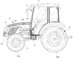
도 2는 본 발명의 실시 예에 따른 농업용 작업차의 전체 측면도.
도 3은 도 2에 도시된 작업차의 원동부 측면 개략도.
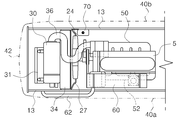
도 4는 도 2에 도시된 작업차의 원동부 평면 개략도.
도 5는 도 3에서 보조 물탱크 취부와 관련된 구성요소만을 발췌하여 도시한 분해 사시도.
도 6은 도 5에 따른 결합 사시도.
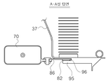
도 7은 도 6을 A-A선 방향에서 바라본 단면도.
도 8은 브라켓 결합부의 바람직한 다른 실시 예를 확대 도시한 도면.BRIEF DESCRIPTION OF THE DRAWINGS Fig. 1 is a perspective view of a driving section of a conventional agricultural work vehicle according to the prior art; Fig.
2 is an overall side view of an agricultural work vehicle according to an embodiment of the present invention;
Fig. 3 is a schematic plan view of the driving side of the work vehicle shown in Fig. 2; Fig.
Fig. 4 is a plan view of a radial part of the work vehicle shown in Fig. 2; Fig.
FIG. 5 is an exploded perspective view showing only the components related to the auxiliary water tank installation in FIG. 3; FIG.
FIG. 6 is an assembled perspective view according to FIG. 5; FIG.
Fig. 7 is a cross-sectional view of Fig. 6 taken along the line AA; Fig.
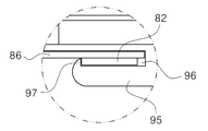
8 is an enlarged view of another preferred embodiment of the bracket coupling portion;
이하, 첨부도면을 참조하여 본 발명의 바람직한 실시예를 상세히 설명하기로 하되, 본 발명을 설명함에 있어 공지된 구성에 대해서는 그 상세한 설명은 생략하며, 또한 발명의 요지를 불필요하게 흐릴 소지가 있는 구성에 대해서도 그 상세한 설명은 생략하기로 한다.Hereinafter, preferred embodiments of the present invention will be described in detail with reference to the accompanying drawings. However, the detailed description of known configurations in describing the present invention will be omitted, and a configuration which may unnecessarily obscure the gist of the present invention The detailed description thereof will be omitted.
도 2는 본 발명의 실시 예에 따른 농업용 작업차의 전체 측면도이며, 도 3, 도 4는 각각, 도 2에 도시된 작업차의 원동부 측면 및 평면 개략도를 나타내고 있다. FIG. 2 is an overall side view of an agricultural work vehicle according to an embodiment of the present invention, and FIGS. 3 and 4 show a plan view and a plan view, respectively, of the work vehicle shown in FIG.
이들 도면을 참조하여 본 발명의 실시 예에 따른 농업용 작업차의 전체적인 구성부터 개략적으로 살펴보기로 하되, 운전석이 캐빈에 의해 보호된 캐빈형 구조를 예로 들어 설명하기로 한다.Referring to these drawings, a general configuration of an agricultural work vehicle according to an embodiment of the present invention will be schematically described, and a cabin type structure in which a driver's seat is protected by a cabin will be described as an example.
도 2 내지 도 4를 참조하면, 본 발명의 실시 예에 따른 농업용 작업차는, 좌우 한 쌍의 전륜(FW)과 후륜(RW)으로 구성된 주행륜을 구비한다. 그리고 전륜(FW)과 후륜(RW) 사이의 기체에는 기체 조작을 위한 운전석(1)이 자리한다. 2 to 4, an agricultural work vehicle according to an embodiment of the present invention includes a traveling wheel constituted by a pair of left and right front wheels FW and rear wheels RW. A driver's
차량 후미에는 레이크(rake), 로터베이터(rotavator), 플라우(plow), 해로우(harrow)와 같은 작업기를 승강 가능하게 연결하는 승강형 견인장치(6, 3점식 승강장치)가 마련되며, 운전석(1)은 박스형 구조물인 캐빈(2)에 덮여 외부로부터 보호되고, 운전석(1)의 전방에는 보닛(4)으로 둘러싸인 엔진 룸이 마련된다. At the rear of the vehicle, there is provided an elevating type traction device (6, 3-point elevating device) for vertically connecting work machines such as rake, rotavator, plow and harrow, (1) is covered by a cabin (2) and protected from the outside, and an engine room surrounded by a bonnet (4) is provided in front of the driver's seat (1).
엔진 룸에는 엔진(5)을 비롯해 수많은 전기 및 기계부품 등이 취부되어 원동부(3)를 구성한다. 이때 엔진(5)은 풋악셀페달 또는 핸드악셀레버의 변위 값에 기반한 엔진제어유닛(ECU, 미도시)의 제어로서 출력이 조절되는 전자식 다기통 엔진이거나 케이블 변위로 출력이 조절되는 기계식 엔진일 수 있다.In the engine room, a large number of electrical and mechanical parts, including the
보닛(4)에 의해 보호되는 엔진 룸 저부에 엔진(5)이 차체 길이방향을 따라 길게 배치되며, 운전석(1)에는 전륜 조향을 위한 조향 핸들(스티어링 휠, 11)을 비롯해, 기체 조작을 위한 각종 레버, 버튼, 그리고 스위치가 마련되어 있다. 그리고 전륜 조향 조작을 위한 스티어링컬럼유닛(10)과 조향 핸들(11)이 마련된다. The
엔진(5)이 출력하는 동력 중 비변속 동력은 미션케이스(9) 내에서 엔진 출력축과 직결되는 동력 취출용 PTO 축(미도시)을 거쳐 차량 후방에 연결되는 작업기 구동을 위한 동력으로 제공되며, 미션케이스(9) 내 주변속장치와 부변속장치를 거쳐 변속된 동력은 주행계 구동축을 통해 주행동력으로 제공된다.The non-shifting power of the
엔진 룸을 덮는 보닛(4)은, 좌우의 측면 커버(40a)(40b), 통기 가능한 전면 커버(42) 및 헤드라이트를 구비한 상부 커버(44)로 구성된다. 측면 커버(40a)(40b) 및 전면 커버(42)는 앞차축 프레임(13) 및 보닛 취부대(14)에 지지를 받고, 상부 커버(44)는 상기 보닛 취부대(14)의 상부에 구비된 힌지점(P)을 중심으로 하는 상향 개폐식으로 구성된다.The
보닛으로 덮인 엔진 룸 안의 원동부 구조에 대해 좀 더 구체적으로 살펴보기로 한다.Let's take a more detailed look at the engine structure in the engine room covered with the bonnet.
도 3 및 도 4와 같이, 엔진(5)의 전방에는 라디에이터(34)가 설치된다. 엔진(5)의 냉각수 재킷과 상기 라디에이터(34) 사이를 냉각수가 순환하면서 엔진(5)을 적정 온도로 냉각시키며, 엔진(5)의 출력축(21)이 출력하는 동력으로 엔진(5) 전면의 냉각팬(24)과 엔진(5) 측부에 취부된 발전기(25)가 구동된다. As shown in Figs. 3 and 4, a
냉각팬(24)의 구동으로 차량 전방에서 라디에이터(34) 측으로 외기가 강제 도입되어 라디에이터(34)를 순환하는 냉각수가 냉각되고, 라디에이터(34) 전방의 엔진 룸 상부공간에는 에어클리너(30)가 설치된다. 그리고 에어클리너(30)에서 연장된 흡기관(36)이 엔진(5)의 일측에 설치된 흡기매니폴드(50)에 접속된다.The cooling water circulating in the
흡기매니폴드(50) 대향부 타측의 엔진(5) 배기 측에는 배기매니폴드(52)가 구비된다. 그리고 라디에이터(34) 후방의 상기 배기매니폴드(52) 상부에는 DPF와 같은 배기가스처리장치(60)가 배치된다. 이때 상기 배기매니폴드(52)의 배기가스 출구 측이 상기 배기가스처리장치(60)의 배기가스 유입 측에 연결된다. An
라디에이터(34)의 전방에는 오일 냉각을 위한 오일 쿨러(32)가 구비된다. 또한 상기 오일 쿨러(32)의 전방에는 콘덴서(33, 논 캐빈 타입의 경우 생략될 수 있음)가 설치된다. 그리고 상기 에어클리너(30) 하부의 상기 콘덴서(33) 전방에는 배터리(31)가 설치되며, 배터리(31)에서 연장된 전원 케이블이 작업차의 각부에 배치된 전기부품에 연결된다.An
라디에에터(34)와 엔진(30) 사이에는 상기 냉각팬(24) 주변을 둘러싸도록 슈라우드(37)가 설치된다. 슈라우드(37)는 냉각팬(24) 회전 시 상기 라디에이터(34)로부터 냉각팬(32)을 향하는 도풍로를 형성한다. 슈라우드(37)는 라디에이터(34)를 감싸는 부분과, 냉각팬(24) 주위를 둘러싸는 부분으로 구성된다.A
슈라우드(37)의 외부 일 측면(기체 전진 주행 방향에 대해 우측면)에는 장착 브라켓()이 설치된다. 그리고 장착 브라켓(80)을 통해 라디에이터(34)와 엔진(5) 사이의 엔진 룸 상부 측방에 보조 물탱크(70)가 설치된다. 이때 보조 물탱크(70)에는 라디에이터(22)의 오버 플로우 분의 냉각수가 저장되고, 냉각수가 부족할 경우 냉각수를 보충하는 역할을 한다.A mounting bracket () is provided on one side of the outer side of the shroud 37 (the right side with respect to the gas advancing direction). An
도면 중 미설명 부호 13은 상기 원동부를 구성하는 구성요소들이 탑재되는 앞차축 프레임을 가리킨다.In the figure,
상기 보조 물탱크의 취부와 관련해서는 이하 도 5 내지 도 7을 참조하기로 한다.With reference to the mounting of the auxiliary water tank, reference is made to Figs. 5 to 7 below.
도 5는 도 3에서 보조 물탱크 취부와 관련된 구성요소만을 발췌하여 도시한 분해 사시도이며, 도 6은 도 5에 따른 결합 사시도이다. 그리고 도 7은 도 6을 A-A선 방향에서 바라본 단면도이다.FIG. 5 is an exploded perspective view showing only the components related to the auxiliary water tank installation in FIG. 3, and FIG. 6 is an assembled perspective view according to FIG. And Fig. 7 is a cross-sectional view taken along line A-A of Fig.
도 5 내지 도 7을 참조하면, 라디에이터의 외면부를 둘러싸는 슈라우드(37)의 외부 일 측면에 장착 브라켓(80)이 설치된다. 장착 브라켓(80)의 조립을 위해 슈라우드(37) 일 측면에 브라켓 결합부(86)가 구성되고, 상기 브라켓 결합부(86)에 장착 브라켓(80)의 일부가 구속되고 장착 브라켓(80)의 다른 일부는 상기 슈라우드(37) 일면에 볼트 고정된다.5 to 7, a mounting
브라켓 결합부(86)는 바람직하게, 상기 슈라우드(37) 일 측면 상부에 슈라우드(37)의 전후 두께 방향으로 형성되며 상기 장착 브라켓(80)의 하단부를 지지하는 지지부재(92)를 구비한다. 또한 상기 지지부재(92) 상부에 형성되며 상기 장착 브라켓(80)의 측부를 상기 슈라우드(37) 일 측면에 대해 구속하는 홀딩부재(94)를 포함한다.The
지지부재(92)에는 지지부재(92)의 길이방향으로 안내홈이 형성된다. 상기 안내홈의 일단 진입 측에 상기 장착 브라켓(80)의 하단 모서리가 끼워진 채 상기 안내홈을 따라 장착 브라켓(80)의 하단부가 지지부재(92)에 슬라이드 조립된다. 이때 상기 안내홈은 생략될 수 있으며, 상기 장착 브라켓(80)의 하단부를 지지할 수 있는 구조라면 특별한 제한은 없다.A guide groove is formed in the
홀딩부재(94)는 슈라우드(37) 일 측면과의 사이에 상기 장착 브라켓(80)의 가장자리 일부를 구속할 수 있도록 소정의 요홈부(96)를 형성시키는 다수의 홀딩핀(95)으로 이루어진 구성일 수 있다. 그러나 도면에 도시된 형태의 홀딩핀(95)에 국한되는 것은 아니며, 장착 브라켓(80)의 가장자리 일부가 끼워져 구속될 수 있는 형태라면 특별한 제한은 없다.The holding
한편, 장착 브라켓(80)은 상기 지지부재(92)의 지지를 받고 홀딩부재(94)에 구속되는 형태로 조립되는 판형의 조립부(82)와, 상기 조립부(82)로부터 연장되며 상기 슈라우드(37) 일면에 볼트를 통해 고정되는 고정부(84)를 포함한다. 그리고 상기 조립부(82)로부터 연장되며 보조 물탱크(70)가 조립되는 조립면을 제공하는 장착부(86)를 구비하는 구성일 수 있다.The mounting
보조 물탱크(70)와 조립면을 제공하는 상기 장착부(86)에는 각각, 체결구멍(74)을 형성한 연결부(72)와, 상기 연결부(72)의 체결구멍(74)과 대응되는 볼트구멍(88)이 각각 형성될 수 있다. 물론 볼트를 이용한 결합 외에도 상호 견고한 결합을 구현할 수 있는 구조라면 특별한 제한은 없으며, 연결부와 장착부의 형상 역시 도시된 형태로 한정되는 것은 아니다.The
도 8은 브라켓 결합부의 바람직한 다른 실시 예로서, 홀딩부재(94)를 구성하는 각각의 홀딩핀(95) 선단에 상기 슈라우드(37) 일 측면을 향하여 돌출되도록 걸림돌기(97)를 구성할 수 있다. 이때 상기 걸림돌기(97)는 장착 브라켓(80) 조립 시 상기 조립부(82)의 가장자리 모서리와 맞물려 장착 브라켓(80)이 임의로 이탈되지 않도록 저지한다.8 shows another preferred embodiment of the bracket coupling portion and the locking
이상의 본 발명의 실시 예에 따른 농업용 작업차에 의하면, 여유공간을 유효하게 활용하여 보조 물탱크를 엔진 룸 내에 취부함으로써, 보조 물탱크 취부를 위해 종래와 같이 별도의 공간확보나 주변 구성품의 레이아웃을 변경하지 않아도 되는 장점이 있다.According to the above-described agricultural work vehicle of the present invention, by installing the auxiliary water tank in the engine room by effectively utilizing the free space, it is possible to secure a separate space for the auxiliary water tank mounting, There is an advantage of not having to change.
또한, 라디에이터와 엔진 사이의 엔진 룸 상부의 여유 공간에 보조 물탱크가 취부됨으로써, 유지 보수에 있어서도 용이할 뿐만 아니라, 보조 물탱크 취부를 위한 조립성 또한 개선할 수 있어 제품 양산성 측면에서도 유리한 효과가 기대된다. Further, since the auxiliary water tank is attached to the clearance space above the engine room between the radiator and the engine, it is not only easy to maintenance, but also improves assembling performance for mounting the auxiliary water tank, Is expected.
또한, 슈라우드 일 측면에 브라켓 결합부를 구성하고, 브라켓 결합부에 보조 물탱크 취부를 위한 장착 브라켓을 끼워서 볼트로 고정시키는 단순한 조립구조이면서도, 견고하고 안정적으로 보조 물탱크를 취부할 수 있다는 장점이 있다.Further, there is an advantage that the auxiliary water tank can be firmly and stably mounted, while the bracket coupling portion is formed on the side of the shroud, and the mounting bracket for mounting the auxiliary water tank is inserted into the bracket coupling portion and fixed by bolts .
이상의 본 발명의 상세한 설명에서는 그에 따른 특별한 실시 예에 대해서만 기술하였다. 하지만 본 발명은 상세한 설명에서 언급되는 특별한 형태로 한정되는 것이 아닌 것으로 이해되어야 하며, 오히려 첨부된 청구범위에 의해 정의되는 본 발명의 정신과 범위 내에 있는 모든 변형물과 균등물 및 대체물을 포함하는 것으로 이해되어야 한다.
In the foregoing detailed description of the present invention, only specific embodiments thereof have been described. It is to be understood, however, that the invention is not to be limited to the specific forms thereof, which are to be considered as being limited to the specific embodiments, but on the contrary, the intention is to cover all modifications, equivalents, and alternatives falling within the spirit and scope of the invention as defined by the appended claims. .
1 : 운전석
2 : 캐빈
3 : 원동부
4 : 보닛
5 : 엔진
6 : 승강장치
9 : 미션 케이스
11 : 조향 핸들
13 : 앞차축 프레임
14 : 보닛 취부대
21 ; 출력축
24 : 냉각팬
25 : 발전기
30 : 에어클리너
34 : 라디에이터
36 : 흡기관
37 : 슈라우드
50 : 흡기매니폴드
52 : 배기매니폴드
60 : 배기가스처리장치
70 : 보조 물탱크
80 : 장착 브라켓
90 : 브라켓 결합부1: driver's seat 2: cabin
3: Hexagon 4: Bonnet
5: engine 6: lifting device
9: Mission case 11: Steering handle
13: Front axle frame 14: Bonnet mounting base
21; Output shaft 24: cooling fan
25: generator 30: air cleaner
34: radiator 36: intake pipe
37: Shroud 50: Intake manifold
52: exhaust manifold 60: exhaust gas treatment device
70: auxiliary water tank 80: mounting bracket
90: Bracket coupling part
Claims (7)
A radiator is installed in an engine room surrounded by a bonnet in front of the driver's seat and a shroud surrounding the outer surface of the radiator, a mounting bracket is installed on one side of the shroud, and the engine room between the radiator and the engine And an auxiliary water tank is installed on the upper side.
상기 슈라우드 외부 일 측면에 브라켓 결합부가 구성되고,
상기 브라켓 결합부에 상기 장착 브라켓의 일부가 구속되고 다른 일부는 상기 슈라우드 일면에 볼트 고정된 것을 특징으로 하는 농업용 작업차.
The method according to claim 1,
A bracket coupling portion is formed on one side surface of the shroud,
Wherein a part of the mounting bracket is constrained to the bracket coupling part and another part is fixed to one surface of the shroud.
상기 브라켓 결합부는,
상기 슈라우드 일 측면 상부에 슈라우드의 전후 두께 방향으로 형성되며 상기 장착 브라켓의 하단부를 지지하는 지지부재와;
상기 지지부재 상부에 형성되며 상기 장착 브라켓의 측부를 상기 슈라우드 일 측면에 대해 구속하는 홀딩부재;를 포함하여 구성되는 것을 특징으로 하는 농업용 작업차.
3. The method of claim 2,
Wherein the bracket-
A support member which is formed in the thickness direction of the shroud at the upper side of the shroud and supports the lower end of the mounting bracket;
And a holding member formed on the support member and restricting a side portion of the mounting bracket to one side surface of the shroud.
상기 지지부재에는 상기 장착 브라켓의 하단부가 슬라이드 조립되는 안내홈이 형성된 것을 특징으로 하는 농업용 작업차.
The method of claim 3,
Wherein the support member is formed with a guide groove into which the lower end of the mounting bracket is slidably assembled.
상기 홀딩부재는 슈라우드 일 측면과의 사이에 소정의 요홈부를 형성하는 다수의 홀딩핀으로 구성됨을 특징으로 하는 농업용 작업차.
The method of claim 3,
Wherein the holding member is constituted by a plurality of holding pins which form a predetermined recess between the one side of the shroud and the other side of the shroud.
상기 각각의 홀딩핀 선단에는 걸림돌기가 상기 슈라우드 일 측면을 향하여 돌출되도록 형성된 것을 특징으로 하는 농업용 작업차.
6. The method of claim 5,
Wherein a gripping protrusion is formed on the tip of each of the holding pins so as to protrude toward one side of the shroud.
상기 장착 브라켓은,
상기 브라켓 결합부에 조립되는 판형의 조립부와;
상기 조립부로부터 연장되며 상기 슈라우드 일면에 볼트 고정되는 고정부와;
상기 조립부로부터 연장되며 보조 물탱크가 조립되는 조립면을 제공하는 장착부;로 이루어진 것을 특징으로 하는 농업용 작업차.3. The method of claim 2,
The mounting bracket
A plate-like assembly part assembled to the bracket coupling part;
A fixing part extending from the assembly part and bolted to one surface of the shroud;
And a mounting portion extending from the assembly portion and providing an assembly surface on which the auxiliary water tank is assembled.
Priority Applications (1)
| Application Number | Priority Date | Filing Date | Title |
|---|---|---|---|
| KR1020140188594A KR102275192B1 (en) | 2014-12-24 | 2014-12-24 | Agricultural vehicle |
Applications Claiming Priority (1)
| Application Number | Priority Date | Filing Date | Title |
|---|---|---|---|
| KR1020140188594A KR102275192B1 (en) | 2014-12-24 | 2014-12-24 | Agricultural vehicle |
Publications (2)
| Publication Number | Publication Date |
|---|---|
| KR20160077996A true KR20160077996A (en) | 2016-07-04 |
| KR102275192B1 KR102275192B1 (en) | 2021-07-08 |
Family
ID=56501368
Family Applications (1)
| Application Number | Title | Priority Date | Filing Date |
|---|---|---|---|
| KR1020140188594A Active KR102275192B1 (en) | 2014-12-24 | 2014-12-24 | Agricultural vehicle |
Country Status (1)
| Country | Link |
|---|---|
| KR (1) | KR102275192B1 (en) |
Cited By (1)
| Publication number | Priority date | Publication date | Assignee | Title |
|---|---|---|---|---|
| CN109177717A (en) * | 2018-07-23 | 2019-01-11 | 北京长城华冠汽车科技股份有限公司 | A kind of expansion tank bracket, expansion tank mounting structure and automobile |
Citations (7)
| Publication number | Priority date | Publication date | Assignee | Title |
|---|---|---|---|---|
| JPH11190046A (en) * | 1997-12-25 | 1999-07-13 | Yutani Heavy Ind Ltd | Hydraulic shovel |
| JP2000280760A (en) * | 1999-04-01 | 2000-10-10 | Mitsubishi Agricult Mach Co Ltd | Working traveling car |
| KR200411313Y1 (en) * | 2005-12-12 | 2006-03-13 | 주식회사 두원공조 | Reservoir tank mounting structure for cooling water |
| KR200411311Y1 (en) * | 2005-12-12 | 2006-03-13 | 주식회사 두원공조 | Reservoir tank mounting structure for cooling water |
| KR200411312Y1 (en) * | 2005-12-12 | 2006-03-13 | 주식회사 두원공조 | Reservoir tank mounting structure for cooling water |
| JP2010174854A (en) | 2009-02-02 | 2010-08-12 | Yanmar Co Ltd | Agricultural tractor |
| JP2012102635A (en) * | 2010-11-08 | 2012-05-31 | Yanmar Co Ltd | Working vehicle |
-
2014
- 2014-12-24 KR KR1020140188594A patent/KR102275192B1/en active Active
Patent Citations (7)
| Publication number | Priority date | Publication date | Assignee | Title |
|---|---|---|---|---|
| JPH11190046A (en) * | 1997-12-25 | 1999-07-13 | Yutani Heavy Ind Ltd | Hydraulic shovel |
| JP2000280760A (en) * | 1999-04-01 | 2000-10-10 | Mitsubishi Agricult Mach Co Ltd | Working traveling car |
| KR200411313Y1 (en) * | 2005-12-12 | 2006-03-13 | 주식회사 두원공조 | Reservoir tank mounting structure for cooling water |
| KR200411311Y1 (en) * | 2005-12-12 | 2006-03-13 | 주식회사 두원공조 | Reservoir tank mounting structure for cooling water |
| KR200411312Y1 (en) * | 2005-12-12 | 2006-03-13 | 주식회사 두원공조 | Reservoir tank mounting structure for cooling water |
| JP2010174854A (en) | 2009-02-02 | 2010-08-12 | Yanmar Co Ltd | Agricultural tractor |
| JP2012102635A (en) * | 2010-11-08 | 2012-05-31 | Yanmar Co Ltd | Working vehicle |
Cited By (1)
| Publication number | Priority date | Publication date | Assignee | Title |
|---|---|---|---|---|
| CN109177717A (en) * | 2018-07-23 | 2019-01-11 | 北京长城华冠汽车科技股份有限公司 | A kind of expansion tank bracket, expansion tank mounting structure and automobile |
Also Published As
| Publication number | Publication date |
|---|---|
| KR102275192B1 (en) | 2021-07-08 |
Similar Documents
| Publication | Publication Date | Title |
|---|---|---|
| US10214247B2 (en) | Work vehicle | |
| RU2643410C2 (en) | Snowmobile and fuel tank of snowmobile | |
| KR20140082592A (en) | Agricultural work vehicle | |
| JP6386979B2 (en) | Work vehicle | |
| KR102275197B1 (en) | Agricultural vehicle and intake/cooling module assembling methods of the Agricultural vehicle | |
| US20200047694A1 (en) | Tractor | |
| JP4574414B2 (en) | Saddle riding vehicle | |
| JP6552320B2 (en) | Tractor | |
| US12252204B2 (en) | Radiator support arrangement for a saddle-ride vehicle | |
| JP5700832B2 (en) | Scooter type vehicle | |
| KR20160077996A (en) | Agricultural vehicle | |
| KR101439117B1 (en) | Engine Control Unit equipping structure of agricultural vehicle | |
| JP4870590B2 (en) | Work vehicle | |
| JP5238058B2 (en) | Work vehicle | |
| WO2014024323A1 (en) | Bulldozer | |
| KR101853910B1 (en) | CNG vehicle for agriculture | |
| EP2048334B1 (en) | Vehicular cooling apparatus | |
| KR20120096202A (en) | Engine control unit equipping structure of agricultural vehicle | |
| JP6436852B2 (en) | Work vehicle | |
| JP6398822B2 (en) | Work vehicle | |
| JP7474402B2 (en) | Work vehicles | |
| KR102529833B1 (en) | Exhaust device of Agricultural vehicle | |
| JP6530999B2 (en) | Tractor | |
| JP6444830B2 (en) | Tractor | |
| JP2016175550A (en) | Work vehicle |
Legal Events
| Date | Code | Title | Description |
|---|---|---|---|
| PA0109 | Patent application |
Patent event code: PA01091R01D Comment text: Patent Application Patent event date: 20141224 |
|
| PG1501 | Laying open of application | ||
| A201 | Request for examination | ||
| PA0201 | Request for examination |
Patent event code: PA02012R01D Patent event date: 20191224 Comment text: Request for Examination of Application Patent event code: PA02011R01I Patent event date: 20141224 Comment text: Patent Application |
|
| E902 | Notification of reason for refusal | ||
| PE0902 | Notice of grounds for rejection |
Comment text: Notification of reason for refusal Patent event date: 20201223 Patent event code: PE09021S01D |
|
| E701 | Decision to grant or registration of patent right | ||
| PE0701 | Decision of registration |
Patent event code: PE07011S01D Comment text: Decision to Grant Registration Patent event date: 20210401 |
|
| GRNT | Written decision to grant | ||
| PR0701 | Registration of establishment |
Comment text: Registration of Establishment Patent event date: 20210702 Patent event code: PR07011E01D |
|
| PR1002 | Payment of registration fee |
Payment date: 20210705 End annual number: 3 Start annual number: 1 |
|
| PG1601 | Publication of registration | ||
| PR1001 | Payment of annual fee |
Payment date: 20240702 Start annual number: 4 End annual number: 4 |