KR20160103473A - Tricycle with folding unit - Google Patents
Tricycle with folding unit Download PDFInfo
- Publication number
- KR20160103473A KR20160103473A KR1020150026098A KR20150026098A KR20160103473A KR 20160103473 A KR20160103473 A KR 20160103473A KR 1020150026098 A KR1020150026098 A KR 1020150026098A KR 20150026098 A KR20150026098 A KR 20150026098A KR 20160103473 A KR20160103473 A KR 20160103473A
- Authority
- KR
- South Korea
- Prior art keywords
- folding
- tricycle
- strut
- folding unit
- fixing
- Prior art date
- Legal status (The legal status is an assumption and is not a legal conclusion. Google has not performed a legal analysis and makes no representation as to the accuracy of the status listed.)
- Ceased
Links
Images




Classifications
-
- B—PERFORMING OPERATIONS; TRANSPORTING
- B62—LAND VEHICLES FOR TRAVELLING OTHERWISE THAN ON RAILS
- B62K—CYCLES; CYCLE FRAMES; CYCLE STEERING DEVICES; RIDER-OPERATED TERMINAL CONTROLS SPECIALLY ADAPTED FOR CYCLES; CYCLE AXLE SUSPENSIONS; CYCLE SIDECARS, FORECARS, OR THE LIKE
- B62K17/00—Cycles not otherwise provided for
-
- B—PERFORMING OPERATIONS; TRANSPORTING
- B60—VEHICLES IN GENERAL
- B60Y—INDEXING SCHEME RELATING TO ASPECTS CROSS-CUTTING VEHICLE TECHNOLOGY
- B60Y2200/00—Type of vehicle
- B60Y2200/10—Road Vehicles
- B60Y2200/13—Bicycles; Tricycles
Landscapes
- Engineering & Computer Science (AREA)
- Mechanical Engineering (AREA)
- Automatic Cycles, And Cycles In General (AREA)
Abstract
Description
본 발명은 킥스쿠터(Kick-scooter)에 관한 것으로서, 더욱 상세하게는, 하나의 전륜과 두 개의 후륜을 포함하여 3륜 형태를 취하는 트라이시클(Tri-cycle)에 관한 것이다.BACKGROUND OF THE INVENTION 1. Field of the Invention The present invention relates to a kick-scooter, and more particularly, to a tri-cycle including a front wheel and a rear wheel and having a three-wheel configuration.
상기 트라이시클은 그 구성에 있어서,The tricycle has, in its configuration,
조향(Steering) 수단으로 진행방향을 바꾸도록 구성되는 조향부와,A steering unit configured to change a traveling direction by a steering means,
탑승(Riding)하여 추진력을 얻도록 구성되는 탑승부와,A riding section configured to ride to obtain propulsion,
상기 조향부와 상기 탑승부를 절첩할 수 있도록 구성되는 절첩부를, 포함하여 이루어진다.And a folding unit configured to fold the steering unit and the boarding unit.
상기 탑승부는 2개의 전개빔이 좌우로 배치되고 상기 각 전개빔의 후방 저면에는 후륜이 장착된다. 특히, 상기 후륜이 인클라인드캐스터(Inclinde-Caster)로 제공되는 경우에, 양 전개빔을 수평방향으로 상호 펼치거나 접는 방식으로 전개하면서 인라인스케이트처럼 바퀴로 지면을 옆으로 자르면서 추진력을 얻을 수 있다.In the boarding section, two spreading beams are arranged on the left and right, and a rear wheel is mounted on the rear bottom of each spreading beam. Particularly, when the rear wheel is provided as an incline-caster, the propelling force can be obtained by cutting both sides of the ground with wheels like an inline skate while expanding both of the expanding beams in a horizontal direction or in a folding manner .
다음은, 본 발명과 관련하는 종래기술을 살펴본다.Next, the prior art relating to the present invention will be described.
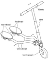
도 1의 예시에는 등록특허 제1033655호(2011.04.29.)가 도시되어 있는 바, 사용자가 손잡이(handle)를 파지한 채로, 핸들지주(strut) 하단의 전륜(front wheel)의 방향을 조향하면서, 좌우로 배치된 전개빔(cross beam) 후단의 발판(footboard)을 양 발로 각각 밟고서 탑승하도록 구성된다. 만일, 상기 발판(footboard) 쪽에 인클라인드캐스터로 제공되는 후륜(rear wheel)을 장착하고, 상기 전개빔(cross beam)을 좌우로 전개하도록 힌지를 두어 구성하면 인라인스케이트처럼 좌우의 상기 후륜을 옆으로 밀거나 당기면서 추진력을 얻을 수 있다.In the example of FIG. 1, registered patent No. 1033655 (Mar. 29, 2011) is shown, in which a user grasps a handle and steers the direction of the front wheel at the bottom of the handle strut , And a footboard on the rear end of a cross beam arranged on the left and right sides, respectively. If a rear wheel provided as an incline caster is mounted on the footboard and a hinge is provided to spread the cross beam to the left and right, You can gain momentum by pushing or pulling.
본 발명은 그 기본적인 구성에 있어서는 필요에 따라서, 상기 등록특허 또는 다른 관련되는 종래기술을 인용하기로 한다.
In the basic structure of the present invention, the aforementioned patent or other related prior art will be cited as necessary.
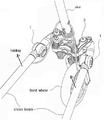
또한, 도 2의 예시에는 접이장치와 관련하여 등록특허 제0928688호(2009.11.19.)가 도시되어 있는 바, 휴대의 편의를 위하여 절첩부(1)를 꺽어서 전개빔(cross beam)을 위 쪽 방향으로 접을(folding) 수 있도록 구성되어 있다.In the example of Fig. 2, the registered patent No. 0928688 (Nov. 19, 2009) is shown in connection with the folding apparatus. For convenience of carrying, the folding unit 1 is folded to form a cross beam So that it can be folded in the direction of the side.
한편, 상기 절첩부(1)의 구성에 있어서, 상기 전개빔(cross beam)의 몸체에 그 구성이 배치되므로, 상기 전개빔(cross beam)을 좌우 수평방향으로 전개하여 주행 추진력을 얻기 위한 구성은 보다 앞 쪽 위치 즉, 핸들지주(strut) 주변에 배치해야 하는 구조를 취하게 된다. 그런데, 상기 핸들지주(strut) 측에는 전륜(front wheel)의 조향을 위한 구성이 집중되어 있으므로, 주행 중에 하중을 견디면서 상기 전개빔(cross beam)의 좌우 한 쌍을 서로 전개하도록 하는 구성을 배치할 곳으로는 사실상, 최적의 배치장소는 아니다. 또한, 상기 스트럿(strut), 상기 전륜(front wheel) 등과 동작 간섭을 피해서 설계를 취해야 하므로 전개빔의 전개각도에 제한을 받을 가능성이 크다.In the configuration of the folding unit 1, since the configuration of the cross beam is arranged in the body of the cross beam, the configuration for obtaining the driving propulsion force by expanding the cross beam in the left and right horizontal directions A structure that must be disposed at a position closer to the steering wheel than the steering wheel. However, since the steering strut side has a configuration for steering the front wheel, a configuration is provided in which a pair of left and right sides of the cross beam are deployed while supporting a load during traveling In fact, it is not the optimal place to place. In addition, since it is necessary to take a design by avoiding operation interference with the strut, the front wheel and the like, there is a great possibility that the deployment angle of the deployment beam is limited.
더하여, 하중을 견디며 좌우로 전개를 반복하며 계속 움직이는 전개빔(cross beam)의 몸체 상에 배치되는 상기 절첩부(1)의 구성은, 사용을 위하여 전개빔(cross beam)을 펼쳐서 고정하는 역할을 하는 상기 절첩부(1)의 고정이 해제될 가능성을 안고 있어서 주행중에 안전사고 가능성을 안고 있다.In addition, the configuration of the folded portion 1, which is placed on the body of a cross beam which continues to move in a leftward and rightward direction while enduring a load, plays a role of spreading and fixing a cross beam for use There is a possibility that a safety accident may occur while the vehicle is running.
본 발명은 상기 전개빔(cross beam)의 전개동작에 있어서, 타 구성요소와의 동작 간섭을 줄이면서, 주행을 위하여 펼쳐놓은 전개빔 고정의 해제를 미연에 방지하고, 그 사용이 더욱 용이한 구성을 제공하고자 하는 것이다.In the deployment operation of the above-mentioned cross beam, the present invention prevents the unfolding of the unfolded beam fixation unfolded for running while reducing the interference with other components, .
전술된 문제와 관련하여 본 발명의 트라이시클은,The tricycles of the present invention in connection with the above-
파이프 형상으로 진행방향의 가로로 배치되며 사용자가 손으로 파지하는 핸들과; 파이프 형상으로 직립하여 배치되며 상단에 상기 핸들을 고정하는 스트럿과; 바퀴로서 상기 스트럿의 하단에 구름운동 가능하게 고정되는 프론트휠을; 포함하는 스티어링유니트와,A handle disposed horizontally in the direction of travel in a pipe shape and held by a user; A strut disposed upright in a pipe shape and fixing the handle to the upper end; A front wheel rotatably fixed to a lower end of the strut as a wheel; Comprising a steering unit,
수평으로 놓이는 보드 형상으로서 사용자가 양발로 밟고 서는 좌우 풋보드와; 파이프 형상으로 진행방향에 세로로 배치되는 좌우 크로스빔과; 상기 좌우 크로스빔의 후방 하단에 구름운동 가능하게 각각 배치되는 좌우 레어휠을; 포함하는 라이딩유니트와,A horizontal board shape, the left and right footboards of the user standing on both feet; A left and right cross beam vertically arranged in the direction of travel in a pipe shape; Left and right rear wheels respectively disposed at rear lower ends of the left and right cross beams so as to be capable of rolling; Comprising a riding unit,
수직방향으로 절첩이 가능한 폴딩유니트를,A folding unit capable of folding in a vertical direction,
포함하여 이루어진다..
또한, 상기 폴딩유니트는, Further, in the folding unit,
상기 스트럿의 외주변에 끼워지는 베이스슬라이드와; 상기 베이스슬라이드의 양측에 각각 결합되어 폴딩되는(절첩되는) 좌우 폴딩파트를; 포함하여 구성된다.A base slide fitted around the outer periphery of the strut; Left and right folding parts that are respectively folded (folded) on both sides of the base slide; .
더하여, 상기 폴딩파트의 후방에는,In addition, behind the folding part,
상기 크로스빔이 수평방향으로 전개될 수 있도록 상기 크로스빔의 전방이 결합되고,The front of the crossbeam is coupled so that the crossbeam can be deployed in the horizontal direction,
상기 레어휠이 인클라인드캐스터 방법으로 구성되어 이루어진다.And the rare wheel is constituted by an incline descender method.
본 발명의 트라이시클 구성에 따르면,According to the tricyclic configuration of the present invention,
트라이시클의 주행 및 추진력 발생을 위하여 수행되는 크로스빔의 전개동작에 있어서,In the deployment operation of the crossbeam performed for the driving of the tricycle and the generation of propulsion,
주행 및 추진력 발생을 위한 사용시에, 상기 크로스빔을 수평으로 전개하기 위한 구성요소가 타 구성요소 예컨대, 스트럿, 프론트휠 등과 동작 간섭의 가능성이 배제되고,During use for driving and propulsion, the possibility of operating interference with other components, such as struts, front wheels, etc., is eliminated in the component for horizontally deploying the cross beam,
또한, 트라이시클의 주행을 위하여 펼쳐놓은 전개빔 고정의 해제를 미연에 방지하고,In addition, the unfolding of the unfolded beam fixation unfolded for the running of the tricycle is prevented in advance,
반대로, 트라이시클의 휴대, 보관을 위하여 폴딩유니트를 절첩시켜(폴딩시켜) 크로스빔을 접어 부피를 줄일 때에도 더욱 사용이 용이한 구성을 제공한다.On the contrary, a folding unit is folded (folded) for folding and folding the cross beam to carry and store the tricycle, thereby providing a more easy-to-use structure.
도 1 및 도 2는 종래기술을 예시한 것으로서,
도 1은 종래기술을 예시하여 보인 전체도이다.
도 2는 다른 예시의 종래기술을 보인 부분도이다.
도 3은 본 발명의 실시를 도시한 것으로서, 전체를 보인 사시도이다.
이하. 본 발명의 폴딩유니트 부분을 중심으로 하여 보인 예시로서,
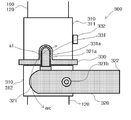
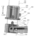
도 4의 A는 사시도이고, 도 4의 B는 측면도이다.
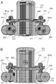
도 5의 A는 정면도이고, 도 5의 B는 배면도이다.
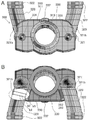
도 6의 A는 평면도이고, 도 6의 B는 저면도로서, 어느 한 부분은 투시하여 도시되어 있다.
도 7은 측면에서 보인 단면도이다.
도 8은 작동상태의 제1 예시를 측면에서 보인 예시도이다.
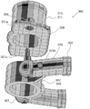
도 9는 저면에서 어느 한 상태를 보인 사시도이다.
도 10은 작동상태의 제2 예시를 측면에서 보인 예시도이다.
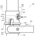
도 11은 다른 작동상태의 제1 예시를 측면에서 보인 예시도이다.
도 12는 다른 작동상태의 제2 예시를 측면에서 보인 예시도이다.Figures 1 and 2 illustrate the prior art,
1 is an overall view illustrating a conventional technique.
Figure 2 is a partial view of another prior art prior art;
3 is a perspective view showing the whole of the embodiment of the present invention.
Below. As an example centered on the folding unit portion of the present invention,
4A is a perspective view, and FIG. 4B is a side view.
Fig. 5A is a front view, and Fig. 5B is a rear view.
Fig. 6A is a plan view, and Fig. 6B is a bottom view, in which one portion is shown in perspective.
7 is a sectional view taken on the side.
Figure 8 is an exemplary view of a first example of an operating state in a side view.
9 is a perspective view showing a state in a bottom surface.
10 is an exemplary view showing a second example of the operating state in a side view.
Figure 11 is an exemplary view in side view of a first example of another operating state.
Figure 12 is an exemplary view in side view of a second example of another operating state.
본 발명은 트라이시클에 관한 것으로서 이하, 첨부된 도면을 중심으로 본 발명의 상세한 설명을 전개하여 나가기로 한다.
DETAILED DESCRIPTION OF THE PREFERRED EMBODIMENTS The present invention relates to a tricycle, and a detailed description of the present invention will now be described with reference to the accompanying drawings.
먼저, 도 3에 예시된 도면과 함께 본 발명의 전체적인 구성을 살펴본다.First, the overall configuration of the present invention will be described with reference to the drawings illustrated in FIG.
본 발명은 스티어링유니트(100)(steering unit), 라이딩유니트(200)(riding unit) 및 폴딩유니트(300)(folding unit)를 포함하여 구성된다. 본 발명의 부재에 있어서는 금속, 플라스틱, 합성수지, 우레탄, 고무 등이 사용된다.
The present invention comprises a
상기 스티어링유니트(100)는 핸들(110)(handle), 스트럿(120)(strut) 및 프론트휠(130)(front wheel)을 포함하여 이루어진다.The
상기 핸들(110)은 사용자가 손으로 조향조작을 가할 수 있도록 상기 스트럿(120)의 상단에 구비된다. 상기 핸들(110)에는 레어휠(230)의 제동(braking)을 위한 켈리퍼브레이크(califer brake) 구성을 추가할 수 있다.The
상기 스트럿(120)은 조향조작을 가할 시에 수평회전을 할 수 있도록 구비된다. 상기 스트럿(120)의 중간에는 사용자의 키에 맞추어서 수직 길이를 조절할 수 있는 구성을 추가할 수 있다.The
상기 프론트휠(130)은 상기 스트럿(120)의 하단에 구름운동 가능하게 구비된다.
The
상기 라이딩유니트(200)는 좌우 풋보드(210), 좌우 크로스빔(220) 및 좌우 레어휠(230)을 포함하여 이루어진다.The
상기 풋보드(210)는 발판의 형태를 취하며 그 저면이 상기 크로스빔(220)의 후단 상면에 고정된다.The
상기 크로스빔(220)은 빔(Beam) 파이프 형태를 취하며, 진행방향의 좌우측에 나란히 병렬로 배치된다.The cross beams 220 take the form of a beam pipe and are arranged in parallel on the right and left sides of the traveling direction.
상기 레어휠(230)은 상기 크로스빔(220)의 후단 저면에 구름운동 가능하게 구비된다. 이때, 공지된 인클라인드캐스터(Inclined-caster) 방식으로 부착할 수 있다.The
이상의 전술된 전체적인 구성에 있어서, 필요에 따라 공지된 종래기술을 인용할 수 있다.
In the above-described overall configuration, a known prior art can be cited as necessary.
다음은, 도 3과 더불어 도 4 이하에 도시된 바와 함께, 본 발명의 요체라 할 수 있는 상기 폴딩유니트(300)에 관하여 집중적으로 살펴본다. 도 4 내지 도 7 도시에서는, 상기 스트럿(120)에 대하여 상기 폴딩파트(320)를 직각이 되도록 펼쳐 고정한 상태를 예시한 것이다.
The following will concentrate on the
상기 폴딩유니트(300)는,The
가운데가 빈 파이프 형상을 취하며 상기 스트럿(120)의 외주변에 끼워지는 베이스슬라이드(310)와,A
상기 베이스슬라이드(310)의 양측에 수평으로 나란히 배치되는 좌우 폴딩파트(320)와,Left and right
상기 베이스슬라이드(310)의 몸통 외주변에 대략 장방형상을 취하여 수평으로 놓이는 고정판(330)을 포함하여 이루어진다.
And a fixing
더욱 구체적으로,More specifically,
상기 베이스슬라이드(310)는 상측에 배치되는 슬라이드파트(311) 및 하측에 배치되는 베이스파트(312)로 분리되어 제공되고, 도 8의 예시와 같이 상기 슬라이드파트(311)는 상기 스트럿(120)의 외주변을 상하로 슬라이딩할 수 있도록(s up, s down) 결합되고, 상기 베이스파트(312)는 상기 스트럿(120)의 외주변에 움직이지 않게 고정된다.8, the
상기 폴딩파트(320)는 좌우 한 쌍으로 제공되며, 상기 베이스파트(312) 좌우 각 측면과 수직굴절 힌지결합(321b)을 하도록 구성한다. 상기 수직굴절 힌지결합(321b)을 회전(굴절)축으로 하여서 상기 폴딩파트(320)는 수직방향으로 회전하여 상기 스트럿(120)과 평행하게 폴딩(절첩)되거나(f up), 반대로 직각으로 펼쳐질(f down) 수 있게 된다.The
도 6 B에 도시된 바에서, 상기 수직굴절 힌지결합(321b)은 상기 베이스파트(312)의 측면지지대(b3)로부터 돌출 형성되는 힌지축(b2) 및 상기 폴딩파트(320)에 관통되어 형성되는 힌지축받이(b1)를 포함하여서, 상기 힌지축(b2)을 상기 힌지축받이(b1)에 끼워서 구성한다.6B, the vertical
또한, 상기 폴딩파트(320)의 전단(321)에는 수직방향의 위로 돌출되는 고정돌기(321a)가 형성되고, 상기 폴딩파트(320)의 후단(322)에는 상기 크로스빔(220)이 연결된다. 즉, 상기 크로스빔(220)은 상기 폴당파트 후단(322)에 움직이지 않게 고정되거나 또는, 수평으로 회전할 수 있도록 수평굴절 힌지결합되어서 좌우 양 크로스빔(220)이 서로 전개되면서 추진력을 발생시키도록 구성될 수 있다.The
상기 고정판(330)은 상기 슬라이드파트(311) 하단의 외주변 테두리에 일체로 형성시키거나 또는, 별도로 제작한 후 단단히 고정시켜 움직이지 않도록 한다. 상기 고정판(330)의 좌우 양측으로는 각각 상기 고정돌기(321a)를 끼워서 고정시킬 수 있는 고정홈돌기(331)가 수직방향 위쪽으로 돌출하여 형성된다.The fixing
도 7, 도 9 및 도 10의 예시에서 확인할 수 있듯이, 상기 고정홈돌기(331)의 내부에는 상기 고정돌기(321a)에 대응하는 구멍이 패인 고정요홈(331a)이 형성되어 있다. 상기 고정요홈(331a)에 상기 고정돌기(321a)를 끼워서 고정하는 것이다. 다시 도 7의 예시에서, 상기 수직굴절 힌지결합(321b)을 회전축으로 하여 상기 고정돌기(321a)가 호 회전(arc)하게 되는데 이때, 상기 고정돌기(321a)가 상기 고정요홈(331a)에 삽입된채로 간섭(a1)이 발생하므로 상기 호 회전(arc)이 불가능하게 된다. 따라서, 이러한 상태에서는 상기 ‘고정’이 절대로 해제될 수 없는 특장점이 있게 되는 것이다.7, 9, and 10, a fixing
이와 같이, 상기 고정홈돌기(331)의 고정요홈에 상기 고정돌기(321a)를 끼워서 상기 폴딩파트(320)가 움직이지 않도록 고정시킨 후, 다시 이를 해제하고자 할 때에는, 도 8의 예시와 같이 상기 스트럿(120)의 길이를 따라서 위로 슬라이딩하도록 상기 슬라이드파트(311)를 위로 잡아 올리면(s up) 이와 함께 상기 고정판(330) 및 상기 고정홈돌기(331)가 한 몸체로서 따라 올라가면서, 상기 고정홈돌기(331) 내부의 고정요홈(331a)에 끼워져 고정되어 있던 상기 고정돌기(321a)가 밖으로 빠져나가게 되어서 자유롭게, 도 7 예시의, 상기 호 회전(arc)을 실시할 수 있으므로 상기 ‘고정’을 완전히 해제시킬 수 있다.8, when the fixing
이러한 방법으로, 좌우 양측의 고정돌기(321a)를 고정홈돌기(331) 내부의 고정요홈(331a) 밖으로 동시에 빼어내어서 좌우 양측의 고정을 해제시킨다. 고정이 해제되면, 도 10의 예시처럼 상기 폴딩파트(320)를 위로 접어서 폴딩(f up)시킬 수 있다. 상기 폴딩파트(320)의 절첩된 폴딩(f up)을 유지하여 보관 및 휴대를 수행한 뒤,In this way, both the left and right fixing
본 발명의 트라이시클을 다시 사용시에는, 반대로, 상기 폴딩파트(320)를 펼치고(f down), 도 8의 예시처럼 슬라이드파트(311)를 아래로 당겨서 슬라이딩시켜 내린다. 이때, 상기 고정요홈(331a)에 상기 고정돌기(321a)가 다시 끼워져 상기 폴딩파트(320)가 움직이지 않도록 고정된다.
When the tricycle of the present invention is used again, on the contrary, the
다음은, 도 11 및 도 12의 예시와 함께, 상기 스트럿(120)으로부터 상기 폴딩파트(320)가 직각으로 펼쳐진 상태를 확실하게 유지하는 추가장치를 살펴본다. 이는, 주행중에 어떤 상황에서도 고정상태의 해제를 미연에 방지하여 안전을 위한 장치로서 중요한 것이다.Next, with reference to FIGS. 11 and 12, consider an additional device to reliably hold the folded
도 11에서, 상기 슬라이드파트(311)의 후방 외주변에는 고정단추 삽입홈(313)을 내고 여기에 고정단추(332)를 삽입하여 구비시킨다. 상기 슬라이드파트(311)를 도 8의 예시처럼 아래로 슬라이딩시켜(s down) 내린 뒤 위치를 맞추고, 상기 고정단추(332)의 일단을 눌러 가압(push)하면 상기 고정단추(332)의 타단이 상기 스트럿의 후방 외주변에 패여서 형성된 고정홈(120a)에 걸치게 되면서 완전한 고정 체결이 되는 것이다. 상기 고정홈(120a)은 상기 고정상태가 유지될 수 있는 위치에 배치되고. 상기 고정단추(332)의 형태에 대응하는 형태로 형성된다.11, a fixing
반대로, 도 12의 예시처럼, 고정을 해제할 시에는 먼저, 상기 고정단추(332)의 타단을 잡아당겨서(pull) 상기 걸치게 되는 상태를 해제시키고, 다음, 도 8의 예시처럼 상기 슬라이드파트(311)를 위로 슬라이딩(s up) 시켜 잡아올린 후, 상기 고정돌기(321a)가 상기 고정요홈(331a)로부터 빠져나오게 한다. 이러한 방법으로 펼져진 상기 폴딩유니트(300)가 접히지 않도록 고정된 상태를 완전히 해제할 수 있는 것이다.On the other hand, as shown in FIG. 12, when releasing the fixation, first, the other end of the
100 : 스티어링유니트
110 : 핸들
120 : 스트럿
130 : 프론트휠
200 : 라이딩유니트
210 : 풋보드
220 : 크로스빔
230 : 레어휠
300 : 폴딩유니트
310 : 베이스슬라이드
320 : 폴딩파트
330 : 고정판100: Steering unit
110: Handle
120: Struts
130: Front wheel
200: Riding unit
210: Footboard
220: Cross beam
230: Rear wheel
300: Folding unit
310: Base slide
320: folding part
330: Fixed plate
Claims (3)
진행방향의 가로로 배치되며 사용자가 손으로 파지하는 핸들; 직립하여 배치되며 상단에 상기 핸들을 고정하는 스트럿; 상기 스트럿의 하단에 구름운동 가능하게 고정되는 프론트휠;을 포함하는 스티어링유니트와,
수평으로 놓이며 사용자가 양 발로 밟고 서는 좌우 풋보드; 진행방향의 세로로 배치되는 좌우 크로스빔; 상기 좌우 크로스빔의 후방 하단에 구름운동 가능하게 각각 배치되는 좌우 레어휠;을 포함하는 라이딩유니트와,
수직방향으로 절첩이 가능한 폴딩유니트를,
포함하는 것을 특징으로 하는 폴딩유니트를 구비한 트라이시클.For the tricycle.
A handle disposed laterally in the direction of travel and gripped by a user; A strut disposed upright and securing the handle to a top; And a front wheel fixed to the lower end of the strut so as to be capable of rolling,
Left and right footboards placed horizontally and treaded by the user on both feet; Right and left cross beams arranged vertically in the traveling direction; And a left and right rear wheel disposed to be capable of rolling on the rear lower ends of the left and right cross beams,
A folding unit capable of folding in a vertical direction,
The tricycle comprising a folding unit.
상기 폴딩유니트는,
상기 스트럿의 외주변에 끼워지는 베이스슬라이드;
상기 베이스슬라이드의 양측에 각각 결합되어 폴딩되는 좌우 폴딩파트;
포함하여 구성되는 것을 특징으로 하는 폴딩유니트를 구비한 트라이시클.The method according to claim 1,
The folding unit includes:
A base slide fitted around the outer periphery of the strut;
Left and right folding parts joined to and folded on both sides of the base slide;
Wherein the tricycle comprises a folding unit.
상기 폴딩유니트는,
상기 스트럿의 외주변에 끼워지는 베이스슬라이드;
상기 베이스슬라이드의 양측에 각각 결합되어 폴딩되는 좌우 폴딩파트;
를 포함하여 구성되고,
상기 폴딩파트의 후방에는,
상기 크로스빔이 수평방향으로 전개될 수 있도록 상기 크로스빔의 전방이 결합되고,
상기 레어휠이 인클라인드캐스터 방법으로 구성되는 것을 특징으로 하는 폴딩유니트를 구비한 트라이시클.The method according to claim 1,
The folding unit includes:
A base slide fitted around the outer periphery of the strut;
Left and right folding parts joined to and folded on both sides of the base slide;
And,
At the rear of the folding part,
The front of the crossbeam is coupled so that the crossbeam can be deployed in the horizontal direction,
Wherein the rhea wheel is constructed by an incline descender method.
Priority Applications (1)
| Application Number | Priority Date | Filing Date | Title |
|---|---|---|---|
| KR1020150026098A KR20160103473A (en) | 2015-02-24 | 2015-02-24 | Tricycle with folding unit |
Applications Claiming Priority (1)
| Application Number | Priority Date | Filing Date | Title |
|---|---|---|---|
| KR1020150026098A KR20160103473A (en) | 2015-02-24 | 2015-02-24 | Tricycle with folding unit |
Publications (1)
| Publication Number | Publication Date |
|---|---|
| KR20160103473A true KR20160103473A (en) | 2016-09-01 |
Family
ID=56942633
Family Applications (1)
| Application Number | Title | Priority Date | Filing Date |
|---|---|---|---|
| KR1020150026098A Ceased KR20160103473A (en) | 2015-02-24 | 2015-02-24 | Tricycle with folding unit |
Country Status (1)
| Country | Link |
|---|---|
| KR (1) | KR20160103473A (en) |
-
2015
- 2015-02-24 KR KR1020150026098A patent/KR20160103473A/en not_active Ceased
Similar Documents
| Publication | Publication Date | Title |
|---|---|---|
| US5893606A (en) | Multifunctional children gear | |
| US8714582B2 (en) | Ride along board for baby stroller | |
| KR101840583B1 (en) | Transformable folding electric scooter | |
| US9963160B2 (en) | Combined scooter and handcart | |
| KR101206502B1 (en) | The folding bicycle use drive pedal and battery | |
| US10064769B2 (en) | Dual configuration portable wheelchair | |
| US9629763B2 (en) | Rear steer portable wheelchair | |
| KR20110119504A (en) | Sliding board | |
| US20150197311A1 (en) | Foot-sliding quad vehicle with tilt-grip steering | |
| JP2018065544A (en) | Device for riding electric motorcycle | |
| US9889368B1 (en) | Personal transportation device | |
| KR102038032B1 (en) | Riding apparatus having drive motor | |
| KR102150090B1 (en) | Carrier type foldable kick board | |
| KR20160103473A (en) | Tricycle with folding unit | |
| KR101374020B1 (en) | A tricycle kick board | |
| EP3344512A1 (en) | Personal transportation device | |
| CN207433592U (en) | A kind of foldable multifunctional trolley | |
| KR100613014B1 (en) | Tricircle Kickboard | |
| PT11023T (en) | COMPACT CHILD CARRIAGE | |
| KR102160930B1 (en) | Releasably fixing module and foldable kickboard comprising the same | |
| KR100715835B1 (en) | Stepping vehicles | |
| CN107650976B (en) | Multifunctional folding trolley | |
| GB2353772A (en) | Foot operated collapsible scooter | |
| JP2025022614A (en) | Frame structure of small electric vehicle and small electric vehicle | |
| KR200395106Y1 (en) | tricycle kick board |
Legal Events
| Date | Code | Title | Description |
|---|---|---|---|
| A201 | Request for examination | ||
| PA0109 | Patent application |
St.27 status event code: A-0-1-A10-A12-nap-PA0109 |
|
| PA0201 | Request for examination |
St.27 status event code: A-1-2-D10-D11-exm-PA0201 |
|
| P11-X000 | Amendment of application requested |
St.27 status event code: A-2-2-P10-P11-nap-X000 |
|
| P13-X000 | Application amended |
St.27 status event code: A-2-2-P10-P13-nap-X000 |
|
| PN2301 | Change of applicant |
St.27 status event code: A-3-3-R10-R13-asn-PN2301 St.27 status event code: A-3-3-R10-R11-asn-PN2301 |
|
| D13-X000 | Search requested |
St.27 status event code: A-1-2-D10-D13-srh-X000 |
|
| D14-X000 | Search report completed |
St.27 status event code: A-1-2-D10-D14-srh-X000 |
|
| R18-X000 | Changes to party contact information recorded |
St.27 status event code: A-3-3-R10-R18-oth-X000 |
|
| E902 | Notification of reason for refusal | ||
| PE0902 | Notice of grounds for rejection |
St.27 status event code: A-1-2-D10-D21-exm-PE0902 |
|
| PG1501 | Laying open of application |
St.27 status event code: A-1-1-Q10-Q12-nap-PG1501 |
|
| PE0601 | Decision on rejection of patent |
St.27 status event code: N-2-6-B10-B15-exm-PE0601 |
|
| E601 | Decision to refuse application | ||
| PE0601 | Decision on rejection of patent |
St.27 status event code: N-2-6-B10-B15-exm-PE0601 |
|
| P22-X000 | Classification modified |
St.27 status event code: A-2-2-P10-P22-nap-X000 |