KR20170000278A - Pipe module and construction method thereof - Google Patents
Pipe module and construction method thereof Download PDFInfo
- Publication number
- KR20170000278A KR20170000278A KR1020150089311A KR20150089311A KR20170000278A KR 20170000278 A KR20170000278 A KR 20170000278A KR 1020150089311 A KR1020150089311 A KR 1020150089311A KR 20150089311 A KR20150089311 A KR 20150089311A KR 20170000278 A KR20170000278 A KR 20170000278A
- Authority
- KR
- South Korea
- Prior art keywords
- piping
- height
- frame
- support frame
- pipe
- Prior art date
- Legal status (The legal status is an assumption and is not a legal conclusion. Google has not performed a legal analysis and makes no representation as to the accuracy of the status listed.)
- Granted
Links
Images


Classifications
-
- F—MECHANICAL ENGINEERING; LIGHTING; HEATING; WEAPONS; BLASTING
- F16—ENGINEERING ELEMENTS AND UNITS; GENERAL MEASURES FOR PRODUCING AND MAINTAINING EFFECTIVE FUNCTIONING OF MACHINES OR INSTALLATIONS; THERMAL INSULATION IN GENERAL
- F16L—PIPES; JOINTS OR FITTINGS FOR PIPES; SUPPORTS FOR PIPES, CABLES OR PROTECTIVE TUBING; MEANS FOR THERMAL INSULATION IN GENERAL
- F16L9/00—Rigid pipes
- F16L9/18—Double-walled pipes; Multi-channel pipes or pipe assemblies
- F16L9/19—Multi-channel pipes or pipe assemblies
- F16L9/20—Pipe assemblies
-
- F—MECHANICAL ENGINEERING; LIGHTING; HEATING; WEAPONS; BLASTING
- F16—ENGINEERING ELEMENTS AND UNITS; GENERAL MEASURES FOR PRODUCING AND MAINTAINING EFFECTIVE FUNCTIONING OF MACHINES OR INSTALLATIONS; THERMAL INSULATION IN GENERAL
- F16L—PIPES; JOINTS OR FITTINGS FOR PIPES; SUPPORTS FOR PIPES, CABLES OR PROTECTIVE TUBING; MEANS FOR THERMAL INSULATION IN GENERAL
- F16L3/00—Supports for pipes, cables or protective tubing, e.g. hangers, holders, clamps, cleats, clips, brackets
- F16L3/08—Supports for pipes, cables or protective tubing, e.g. hangers, holders, clamps, cleats, clips, brackets substantially surrounding the pipe, cable or protective tubing
-
- F—MECHANICAL ENGINEERING; LIGHTING; HEATING; WEAPONS; BLASTING
- F16—ENGINEERING ELEMENTS AND UNITS; GENERAL MEASURES FOR PRODUCING AND MAINTAINING EFFECTIVE FUNCTIONING OF MACHINES OR INSTALLATIONS; THERMAL INSULATION IN GENERAL
- F16L—PIPES; JOINTS OR FITTINGS FOR PIPES; SUPPORTS FOR PIPES, CABLES OR PROTECTIVE TUBING; MEANS FOR THERMAL INSULATION IN GENERAL
- F16L3/00—Supports for pipes, cables or protective tubing, e.g. hangers, holders, clamps, cleats, clips, brackets
- F16L3/22—Supports for pipes, cables or protective tubing, e.g. hangers, holders, clamps, cleats, clips, brackets specially adapted for supporting a number of parallel pipes at intervals
- F16L3/23—Supports for pipes, cables or protective tubing, e.g. hangers, holders, clamps, cleats, clips, brackets specially adapted for supporting a number of parallel pipes at intervals for a bundle of pipes or a plurality of pipes placed side by side in contact with each other
-
- F—MECHANICAL ENGINEERING; LIGHTING; HEATING; WEAPONS; BLASTING
- F16—ENGINEERING ELEMENTS AND UNITS; GENERAL MEASURES FOR PRODUCING AND MAINTAINING EFFECTIVE FUNCTIONING OF MACHINES OR INSTALLATIONS; THERMAL INSULATION IN GENERAL
- F16M—FRAMES, CASINGS OR BEDS OF ENGINES, MACHINES OR APPARATUS, NOT SPECIFIC TO ENGINES, MACHINES OR APPARATUS PROVIDED FOR ELSEWHERE; STANDS; SUPPORTS
- F16M13/00—Other supports for positioning apparatus or articles; Means for steadying hand-held apparatus or articles
Landscapes
- Engineering & Computer Science (AREA)
- General Engineering & Computer Science (AREA)
- Mechanical Engineering (AREA)
- Supports For Pipes And Cables (AREA)
Abstract
본 발명에 따르면 건물 외부 바닥면(1)의 배관 시공을 위한 배관일체형 모듈(A)에 있어서 배관(100), 상기 배관(100)이 거치되는 가로프레임(220), 상기 가로프레임(220)을 지지하는 지지프레임(230), 상기 지지프레임(230)과 상기 바닥면(1) 사이에 게재되어 상기 가로프레임(220)의 수직도를 조절하는 수직도 조절부(300) 및 상기 배관(100)을 상기 가로프레임(220)에 고정시키는 배관고정부(500)를 포함하는 것을 특징으로 하는 배관일체형 모듈이 제공된다.
본 발명에 따르면 공장에서 선 작업된 모듈화된 개별 배관일체형 모듈을 이용하여 현장에서 손쉽게 배관을 시공할 수 있는 효과가 있다.
구체적으로 공조배관, 급수배관 등의 복수의 배관과 배관을 지지하는 프레임으로 배관모듈을 공장제작하고, 공장제작된 복수의 배관 모듈을 현장으로 반입하여 이를 조립하는 기술로서, 복잡한 배관조립 공정을 단순화 시키고, 이로 인해 공정시간을 단축시킬 수 있다.According to the present invention, in a piping-integrated module A for piping construction on a floor 1 outside a building, a piping 100, a horizontal frame 220 on which the piping 100 is mounted, A verticality adjusting unit 300 disposed between the supporting frame 230 and the bottom surface 1 to adjust the verticality of the horizontal frame 220 and a vertical angle adjusting unit 300 disposed between the supporting frame 230 and the bottom surface 1, And a pipe fixing part (500) for fixing the pipe to the horizontal frame (220).
According to the present invention, there is an effect that piping can be easily constructed on site by using a module-integrated individual piping integrated module pre-worked in a factory.
Specifically, a plurality of piping modules such as air-conditioning piping and water supply piping and a frame supporting the piping are manufactured as a factory, and a plurality of factory-manufactured piping modules are brought into the field and assembled, thereby simplifying a complicated piping assembly process So that the processing time can be shortened.
Description
본 발명은 공장 및 건축구조물의 외부 바닥면에 설치되는 배관일체형 모듈 및 배관일체형 모듈의 설치방법에 관한 것으로서, 보다 상세하게는 공장 제작된 배관일체형 모듈을 이용하여 배관을 시공함으로써 현장작업을 간소화하고 공기를 단축시킬 수 있는 배관일체형 모듈 및 배관일체형 모듈의 설치방법에 관한 것이다.The present invention relates to a piping integrated module and a piping integrated module installed on an outer bottom surface of a factory and an architectural structure. More particularly, the piping is constructed using a factory-assembled piping integrated module, To an installation method of a module with integral pipe and a module with integral pipe which can shorten the air.
일반적으로 플랜트 및 공장 등의 배관시설은 공조배관 및 급수배관 등의 배관을 설치할 때, 배관을 지지하는 지지대를 설치하고, 배관을 설치한다.Generally, piping facilities such as plants and factories are provided with supporting rods for piping, such as air-conditioning piping and water piping, and piping is provided.
즉, 여러 개의 배관 지지대 중 일부 지지대를 설치하고, 공조배관 및 급수배관 등의 배관을 지지대에 조립하는 공정을 반복하여 배관시설을 완공한다.That is, a piping facility is completed by installing a part of a plurality of piping supports and repeating the process of assembling the piping such as the air conditioning piping and the water supply piping to the supporting platform.
위 경우, 지지대를 설치 한 이후 배관 하나 하나를 각각 설치하기 때문에 공정시간이 길고, 작업효율이 떨어지는 문제점이 있다.In this case, since each piping is installed after installing the supporting rods, the process time is long and the working efficiency is low.
본 발명은 상기와 같은 문제점을 해결하기 위하여 도출된 것으로서, 본 발명의 목적은 공장에서 모듈화된 개별 배관모듈을 이용하여 현장에서 손쉽게 배관을 시공할 수 있는 배관일체형 모듈 및 배관일체형 모듈의 설치방법을 제공하는 것에 있다. SUMMARY OF THE INVENTION The present invention has been made to solve the above problems, and it is an object of the present invention to provide a piping integrated module and a piping integrated module capable of easily installing piping in the field by using individual piping modules modularized in a factory. .
본 발명의 다른 목적은 현장작업을 최소화하여 공사기간을 단축시킬 수 있는 배관일체형 모듈 및 배관일체형 모듈의 설치방법을 제공하는 것에 있다. It is another object of the present invention to provide a piping integrated module and a piping integrated module installation method which can shorten a construction period by minimizing field work.
본 발명의 또 다른 목적은 배관모듈을 이용한 간이화된 설치작업을 수행하도록 함으로써 현장에서의 안전사고를 예방하고, 시공인력 투입을 최소화할 수 있는 배관일체형 모듈 및 배관일체형 모듈의 설치방법을 제공하는 것에 있다. It is another object of the present invention to provide a method for installing a module with integrated pipe and a method for installing a module with integrated pipe, which can prevent a safety accident in the field by minimizing installation work by using a piping module have.
상기 과제의 해결을 위하여, 본 발명은 건물 외부 바닥면(1)의 배관 시공을 위한 배관일체형 모듈(A)에 관한 것으로서 배관(100), 상기 배관(100)이 거치되는 가로프레임(220), 상기 가로프레임(220)을 지지하는 지지프레임(230), 상기 지지프레임(230)과 상기 바닥면(1) 사이에 게재되어 상기 가로프레임(220)의 수직도를 조절하는 수직도 조절부(300) 및 상기 배관(100)을 상기 가로프레임(220)에 고정시키는 배관고정부(500);를 포함하는 것을 특징으로 하는 배관일체형 모듈을 제시한다.In order to solve the above problems, the present invention relates to a piping integrated module (A) for piping construction on a floor (1) outside a building, comprising a piping (100), a horizontal frame (220) A
상기 가로프레임(220)은 복수로 설치되며, 상기 복수의 가로프레임(220)을 결합하는 세로프레임(210)을 더 포함하는 것이 바람직하다.It is preferable that the
상기 배관고정부(500)는 상기 가로프레임(220)에 결합되는 받침부(510) 및 상기 배관(100)을 둘러 상기 가로프레임(220)에 결합되는 고정부(520)를 포함하는 것이 바람직하다.The
상기 수직도 조절부(300)는 상기 지지프레임(230)의 높이를 조절하는 높이조절부(310) 및 상기 높이조절부(310)에 의해 조절된 높이에서 상기 지지프레임(230)을 고정시키는 고정부(320)를 포함하되, 상기 높이조절부(310)는 상기 지지프레임(230)의 하단에 결합된 단부 플레이트(311), 상기 단부 플레이트(311)를 관통하여 형성된 볼트구멍(312) 및 상기 볼트구멍(312)에 삽입됨과 아울러, 볼팅 수준에 따라 상기 단부 플레이트(311)의 높이를 변화시키는 높이조절 볼트(313)를 포함하는 것이 바람직하다.The
상기 높이조절 볼트(313)는 상기 단부 플레이트(311)의 중심축을 기준으로 대응되는 위치에 복수로 형성되는 것이 바람직하다.The
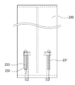
상기 고정부(320)는 상기 단부 플레이트(311)와 상기 지면(1) 사이에 설치되는 바닥 플레이트(321) 상기 바닥 플레이트(321)와 결합됨과 아울러, 상기 지지 프레임(230)과 접촉된 결합판(322) 및 상기 지지 프레임(230)과 상기 결합판(322)을 결합시키는 고정부재(323)를 포함하되, 상기 고정부재(323)는 상기 지지 프레임(230)에 형성된 제1관통홀(314) 및 상기 결합판(322)에 형성된 제2관통홀(323)을 관통하여 볼트 결합되는 것이 바람직하다.The
상기 제1관통홀(314) 및 상기 제2관통홀(323)은 서로 대응되는 위치에 형성되며, 상기 지지 프레임(230)의 길이방향으로 장직경을 갖는 장공인 것이 바람직하다.The first through
바닥 플레이트(321)에는 상기 지면(1)에 형성된 앵커(325)가 삽입되는 앵커삽입홀(324)이 형성된 것이 바람직하다. The
상기 배관일체형 모듈의 설치방법은 조립되어 현장반입된 배관일체형 모듈을 상기 앵커(325)의 위치로 운반하는 모듈운반단계, 상기 앵커사입홀(324)를 상기 앵커(325)에 삽입 후 결합하는 앵커결합단계, 상기 높이조절볼트(313)을 조절하여 상기 지지프레임(230)의 각도와 높이를 조절하는 프레임조절단계, 상기 제1관통홀(314)과 상기 제2관통홀(323)을 결합하는 프레임결합단계를 포함 한다.The method of installing the integrated module of piping includes a module transportation step of transporting a pipeline integrated module to the position of the anchor (325) assembled and transported to the site, a step of inserting the anchor insertion hole (324) into the anchor (325) A frame adjusting step of adjusting the height and the height of the
상기 모듈운반단계는 상기 수직도조절부(300)의 하단에 설치됨과 아울러, 바퀴(420)와 대차플레이트(410)를 구비한 이동식대차(400)에 의해 운반되는 것이 바람직하다.It is preferable that the module transporting step is carried by a moving
본 발명에 따르면 공장에서 선 작업되어 모듈화된 배관일체형 모듈을 이용하여 현장에서 손쉽게 배관을 시공할 수 있는 효과가 있다. According to the present invention, there is an effect that piping can be easily installed in the field by using a module-integrated module which is pre-assembled in a factory.
본 발명에 따르면 현장작업을 최소화하여 공사기간을 단축시킬 수 있는 효과가 있다. According to the present invention, it is possible to minimize the field work and shorten the construction period.
본 발명에 따르면 배관모듈을 이용한 간이화된 설치작업을 수행하도록 함으로써 현장에서의 안전사고를 예방하고, 시공인력 투입을 최소화할 수 있는 효과가 있다. According to the present invention, a simplified installation work using the piping module is performed, thereby preventing a safety accident on site and minimizing the input of construction manpower.
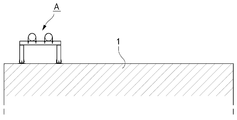
도 1은 본 발명의 일 실시예의 배관일체형 모듈 설치도.
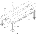
도 2는 본 발명의 일 실시예에 따른 배관일체형 모듈 사시도.
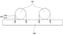
도 3은 본 발명의 일 실시예에 따른 가로프레임과 결합된 배관 단면도.
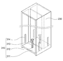
도 4는 본 발명의 일 실시예에 따른 지지프레임과 높이조절부의 사시도.
도 5는 본 발명의 일 실시예에 따른 지지프레임과 높이조절부 측면도.
도 6은 본 발명의 일 실시예에 따른 결합판 사시도.
도 7은 본 발명의 일 실시예에 따른 높이조절부와 결합판이 결합된 사시도
도 8은 본 발명의 일 실시예에 따른 이동식대차의 사시도.
도 9는 본 발명의 일 실시예에 따른 결합판의 앵커결합 단면도. BRIEF DESCRIPTION OF THE DRAWINGS FIG. 1 is a block diagram of a piping integrated type module according to an embodiment of the present invention. FIG.
FIG. 2 is a perspective view of a pipe-integrated module according to an embodiment of the present invention; FIG.
3 is a cross-sectional view of a piping coupled with a transverse frame in accordance with an embodiment of the present invention.
4 is a perspective view of a support frame and a height adjuster according to an embodiment of the present invention.
FIG. 5 is a side view of a support frame and a height adjusting portion according to an embodiment of the present invention. FIG.
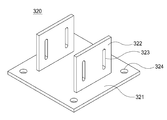
6 is a perspective view of an engaging plate according to an embodiment of the present invention;
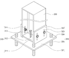
FIG. 7 is a perspective view illustrating a perspective view of a height adjusting unit according to an embodiment of the present invention,
8 is a perspective view of a mobile bogie according to an embodiment of the present invention.
9 is an anchor coupling sectional view of a coupling plate according to an embodiment of the present invention.
본 발명에 따른 건물 외부 바닥면에 설치되는 배관일체형 모듈 및 배관일체형 모듈의 설치방법의 실시예를 첨부도면을 참조하여 상세히 설명하기로 하며, 첨부 도면을 참조하여 설명함에 있어, 동일하거나 대응하는 구성 요소는 동일한 도면 번호를 부여하고 이에 대한 중복되는 설명은 생략하기로 한다.The present invention is not limited to the above-described embodiments, and various changes and modifications may be made without departing from the scope of the present invention as set forth in the accompanying drawings. Elements are denoted by the same reference numerals, and redundant description thereof will be omitted.
또한, 이하 사용되는 제1, 제2 등과 같은 용어는 동일 또는 상응하는 구성 요소들을 구별하기 위한 식별 기호에 불과하며, 동일 또는 상응하는 구성 요소들이 제1, 제2 등의 용어에 의하여 한정되는 것은 아니다.It is also to be understood that the terms first, second, etc. used hereinafter are merely reference numerals for distinguishing between identical or corresponding components, and the same or corresponding components are defined by terms such as first, second, no.
또한, 결합이라 함은, 각 구성 요소 간의 접촉 관계에 있어, 각 구성 요소 간에 물리적으로 직접 접촉되는 경우만을 뜻하는 것이 아니라, 다른 구성이 각 구성 요소 사이에 개재되어, 그 다른 구성에 구성 요소가 각각 접촉되어 있는 경우까지 포괄하는 개념으로 사용하도록 한다.In addition, the term " coupled " is used not only in the case of direct physical contact between the respective constituent elements in the contact relation between the constituent elements, but also means that other constituent elements are interposed between the constituent elements, Use them as a concept to cover each contact.
이하, 첨부도면을 참조하여 본 발명의 일 실시예에 따른 배관일체형 모듈 및 배관일체형 모듈의 설치방법에 관하여 상세히 설명한다.DETAILED DESCRIPTION OF THE PREFERRED EMBODIMENTS Hereinafter, a method of installing a pipe-integrated module and a pipe-integrated module according to an embodiment of the present invention will be described in detail with reference to the accompanying drawings.
본 발명에 의한 건물 외부 바닥면(1)의 배관 시공을 위한 배관일체형 모듈은 배관(100), 배관(100)이 거치되는 가로프레임(220), 가로프레임(220)을 지지하는 지지프레임(230), 지지프레임(230)과 바닥면(1) 사이에 게재되어 가로프레임(220)의 수직도를 조절하는 수직도 조절부(300) 및 배관(100)을 가로프레임(220)에 고정시키는 배관고정부(500)로 구성된다. The module with integrated piping for the piping construction of the
종래의 배관설치작업은 배관을 지지하는 프레임을 현장에서 조립하고, 프레임에 배관을 고정하는 공정으로 많은 현장작업이 요구되었으나, 본 발명의 일실시 예에 따른 배관일체형 모듈을 이용한 배관의 시공은 공장에서 선 제작된 배관모듈을 배관 형성 위치로 이동시키고, 각도와 높이를 조절한 후 각 모듈을 연결하는 것만으로 배관설치 작업을 완료할 수 있으므로, 현장작업이 유리하고, 공사기간을 단기화 할 수 있는 효과를 갖는다. In the conventional piping installation work, a frame supporting the piping is assembled in the field and the piping is fixed to the frame, and a lot of field work has been required. However, in the piping construction using the piping integrated module according to the embodiment of the present invention, The piping module can be completed by simply moving the piping module pre-assembled to the piping formation position, adjusting the angle and height, and then connecting each module, so that the field work is advantageous and the construction period can be shortened Effect.
가로프레임(220)은 복수로 설치되며, 복수의 가로프레임(220)을 결합하는 세로프레임(210)을 더 포함하는 것이 바람직하다.It is preferable that the
이 경우, 배관의 크기와 모듈의 크기에 따라 가로프레임(220)과 세로프레임(210)을 결합하여 지지프레임을 형성하는 구조를 취할 수 있기 때문에 안정적으로 배관을 지지하는 배관일체형 모듈(A)을 제작할 수 있다. In this case, since the structure in which the support frame is formed by combining the
또한, 가로프레임(220)과 세로프레임(210)을 이용하여 격자형으로 조립된 배관일체형 모듈(A)은 배관일체형 모듈이 운반되고 설치되는 동안 안정적으로 배관일체형 모듈을 지지하여 배관의 손상을 방지할 수 있다. In addition, the integrated pipe module A assembled in a lattice form using the
배관고정부(500)는 가로프레임(220)에 결합되는 받침부(510) 및 배관(100)을 둘러 가로프레임(220)에 결합되는 고정부(520)를 포함하는 것이 바람직하다.The
이 경우 배관(100)을 가로프레임(220)에 고정된 받침부(510) 상면에 올려놓고 고정부(520)를 볼트 결합하는 구조를 취하고 있기 때문에 고정부(520)의 가로프레임(220) 결합이 용이하고, 배관일체형 모듈(A)의 조립을 빠르게 수행할 수 있다. In this case, since the
수직도 조절부(300)는 지지프레임(230)의 높이를 조절하는 높이조절부(310); 및 높이조절부(310)에 의해 조절된 높이에서 상기 지지프레임(230)을 고정시키는 고정부(320)를 포함하되, 높이조절부(310)는 지지프레임(230)의 하단에 결합된 단부 플레이트(311), 단부 플레이트(311)를 관통하여 형성된 볼트구멍(312) 및 볼트구멍(312)에 삽입됨과 아울러 볼팅 수준에 따라 단부 플레이트(311)의 높이를 변화시키는 높이조절 볼트(313)를 포함하는 것이 바람직하다.The
즉, 지지프레임(230)에 설치된 수직도조절부(300)는 배관일체형 모듈(A)의 제작과정에서 발생하는 제작오차와 건물 외부 바닥면(1)의 편평도에 따른 오차를 조절할 수 있다. That is, the
이 경우, 높이조절 볼트를 사용하여 볼트의 삽입길이를 조절하여 지지프레임의 길이오차를 수정할 수 있다.In this case, the length of the support frame can be corrected by adjusting the insertion length of the bolt using the height adjusting bolt.
높이조절 볼트(313)는 단부 플레이트(311)의 중심축을 기준으로 대응되는 위치에 복수로 형성되는 것이 바람직하다.Preferably, the
이 경우, 단부 플레이트(311)의 중심축을 기준으로 대응되는 구조로 결합된 볼트의 높이를 서로 다르게 조절함으로써, 중심축을 기준으로 발생한 지지프레임의 각도 조절과 높이 조절이 가능하다. In this case, it is possible to adjust the angle of the support frame and adjust the height of the support frame based on the central axis by adjusting the height of the bolts coupled with the corresponding structure based on the central axis of the
고정부(320)는 단부 플레이트(311)와 지면(1) 사이에 설치되는 바닥 플레이트(321), 바닥 플레이트(321)와 결합됨과 아울러, 지지 프레임(230)과 접촉된 결합판(322) 및 지지 프레임(230)과 결합판(322)을 결합시키는 고정부재(323)를 포함하되, 고정부재(323)는 지지 프레임(230)에 형성된 제1관통홀(314) 및 결합판(322)에 형성된 제2관통홀(323)을 관통하여 볼트 결합되는 것이 바람직하다. The
이 경우, 제1관통홀(314)과 제2관통홀(323)에 볼트가 삽입되어 고정부와 지지프레임을 결합하기 때문에 고정부(320)와 지지프레임(230)의 결합이 용이하고, 작업시간을 단축시킬 수 있다.In this case, since bolts are inserted into the first through
제1관통홀(314) 및 제2관통홀(323)은 서로 대응되는 위치에 형성되며, 지지 프레임(230)의 길이방향으로 장직경을 갖는 장공인 것이 바람직하다.It is preferable that the first through
이 경우, 높이조절 볼트(313)에 의해 지지프레임의 높이가 변화해도 지지프레임(230)의 길이방향으로 장공의 관통홀(314,323)이 형성되어 있기 때문에 고정부(320)와 높이조절부(310)의 볼트결합이 가능해 진다.In this case, even though the height of the support frame is changed by the
바닥 플레이트(321)에는 지면(1)에 형성된 앵커(325)가 삽입되는 앵커삽입홀(324)이 형성된 것이 바람직하다. The
이 경우, 건물 외부 바닥면(1)에 설치된 앵커(325)에 배관일체형 모듈의 앵커삽입홀(324)이 관통되어 너트로 고정되므로 설치공정이 간단하고 작업속도가 빠르다.In this case, since the
이하 본 발명의 일 실시예에 따른 배관일체형 모듈을 이용하여 배관일체형 모듈을 설치하는 방법에 대하여 설명한다. Hereinafter, a method of installing the integrated pipe module using the integrated pipe module according to an embodiment of the present invention will be described.
본 발명의 일 실시예에 따른 배관일체형 모듈을 이용한 배관일체형 모듈의 설치하는 방법은 조립되어 현장반입된 배관일체형 모듈을 앵커(325)의 위치로 운반하는 모듈운반단계, 앵커삽입홀(324)을 상기 앵커(325)에 결합시키는 앵커결합단계, 높이조절볼트(313)을 조절하여, 지지프레임(230)의 각도와 높이를 조절하는 프레임조절단계를 포함하고, 이후 제1관통홀(314)과 제2관통홀(323)을 결합하는 프레임결합단계로 설치된다.A method of installing a module with integrated pipe using a module with integrated pipe according to an embodiment of the present invention includes a module transportation step of transporting a module integrated with a pipeline integrated in the field to a location of an
위 경우, 배관일체형 모듈은 미리 제작되어 현장으로 반입되기 때문에 현장공정이 단순화 되고, 공사기간이 단축된다.In this case, since the integrated module of piping is manufactured in advance and brought into the site, the on-site process is simplified and the construction period is shortened.
배관일체형 모듈(A)의 설치위치에는 배관일체형 모듈이 현장으로 반입되기 전에 앵커(325)가 설치되어 있기 때문에 배관일체형 모듈(A)이 현장 반입된 이후 신속한 결합이 가능하다.Since the
이후, 높이조절 볼트를 조절하여 배관일체형 모듈(A)의 오차를 조절하고 배관일체형 모듈(A)을 설치할 수 있다. Thereafter, the height adjustment bolts are adjusted to adjust the error of the pipe-integrated module (A) and install the pipe-integrated module (A).
이 경우, 배관일체형 모듈(A)은 볼팅 수준에 따라 각도와 높이가 조절되는데 인력에 의한 볼팅작업으로 배관일체형 모듈(A)의 오차를 수정할 수 있으며, 오차 조정 후, 제1관통홀과 제2관통홀을 이용하여 고정부(320)와 높이조절부(310)를 볼트로 결합하기 때문에 공정시간이 빠르다.In this case, the pipe-integrated module A is adjusted in angle and height according to the bolting level, and the error of the pipe-integrated module A can be corrected by the bolting operation by the pulling force. After the error adjustment, Since the fixing
모듈운반단계는 수직도조절부(300)의 하단에 설치됨과 아울러, 바퀴(420)와 대차플레이트(410)을 구비한 이동식대차(400)에 의해 운반되는 것이 바람직하다.It is preferable that the module transporting step is carried by a moving
이 경우, 배관일체형 모듈(A)은 바퀴가 설치된 이동식대차(400)위에 수직도 조절부(300)를 올려놓은 후 현장에서 이동되기 때문에 이동이 간편하다.In this case, the pipe-integrated module A is easy to move since the vertical
이상은 본 발명에 의해 구현될 수 있는 바람직한 실시예의 일부에 관하여 설명한 것에 불과하므로, 주지된 바와 같이 본 발명의 범위는 위의 실시예에 한정되어 해석되어서는 안 될 것이며, 위에서 설명된 본 발명의 기술적 사상과 그 근본을 함께 하는 기술적 사상은 모두 본 발명의 범위에 포함된다고 할 것이다.It will be apparent to those skilled in the art that various modifications and variations can be made in the present invention without departing from the spirit or scope of the invention as defined in the appended claims. It is to be understood that both the technical idea and the technical spirit of the invention are included in the scope of the present invention.
A : 배관일체형 모듈
1 : 건물외부 바닥면
100 : 배관
210 : 세로프레임
220 : 가로프레임
230 : 지지프레임
300 : 수직도조절부
310 : 높이조절부
311 : 단부플레이트
312 : 볼트구멍
313 : 높이조절볼트
314 : 제1관통홀
320 : 고정부
321 : 바닥플레이트
322 : 결합판
323 : 제2관통홀
324 : 앵커삽입홀
325 : 앵커
400 : 이동식대차
500 : 배관고정부A: Integrated piping module 1: Floor outside the building
100: piping 210: vertical frame
220: Horizontal frame 230: Support frame
300: Vertical degree adjusting unit 310: Height adjusting unit
311: end plate 312: bolt hole
313: height adjusting bolt 314: first through hole
320: fixing part 321: bottom plate
322: coupling plate 323: second through hole
324: anchor insertion hole 325: anchor
400: Portable bogie 500: Piping fixing part
Claims (10)
배관(100);
상기 배관(100)이 거치되는 가로프레임(220);
상기 가로프레임(220)을 지지하는 지지프레임(230);
상기 지지프레임(230)과 상기 바닥면(1) 사이에 게재되어 상기 가로프레임(220)의 수직도를 조절하는 수직도 조절부(300); 및
상기 배관(100)을 상기 가로프레임(220)에 고정시키는 배관고정부(500);를 포함하는 것을 특징으로 하는 배관일체형 모듈.
In a piping-integrated module (A) for piping construction of a floor (1) outside a building,
A piping 100;
A horizontal frame 220 on which the piping 100 is mounted;
A support frame (230) for supporting the transverse frame (220);
A vertical adjustment unit 300 disposed between the support frame 230 and the bottom surface 1 to adjust the verticality of the horizontal frame 220; And
And a pipe fixing part (500) for fixing the pipe (100) to the horizontal frame (220).
상기 가로프레임(220)은 복수로 설치되며,
상기 복수의 가로프레임(220)을 결합하는 세로프레임(210);을
더 포함하는 것을 특징으로 하는 배관일체형 모듈.
The method according to claim 1,
The plurality of horizontal frames 220 are installed,
A vertical frame 210 coupling the plurality of horizontal frames 220;
Further comprising a plurality of piping integrated modules.
상기 배관고정부(500)는 상기 가로프레임(220)에 결합되는 받침부(510); 및 상기 배관(100)을 둘러 상기 가로프레임(220)에 결합되는 고정부(520);를 포함하는 것을 특징으로 하는 배관일체형 모듈.
The method according to claim 1,
The pipe fixing part 500 includes a support part 510 coupled to the horizontal frame 220; And a fixing part (520) coupled to the transverse frame (220) around the pipe (100).
상기 수직도 조절부(300)는
상기 지지프레임(230)의 높이를 조절하는 높이조절부(310); 및
상기 높이조절부(310)에 의해 조절된 높이에서 상기 지지프레임(230)을 고정시키는 고정부(320);를 포함하되,
상기 높이조절부(310)는,
상기 지지프레임(230)의 하단에 결합된 단부 플레이트(311);
상기 단부 플레이트(311)를 관통하여 형성된 볼트구멍(312); 및
상기 볼트구멍(312)에 삽입됨과 아울러, 볼팅 수준에 따라 상기 단부 플레이트(311)의 높이를 변화시키는 높이조절 볼트(313);를 포함하는 것을 특징으로 하는 배관일체형 모듈.
4. The method according to any one of claims 1 to 3,
The vertical degree adjusting unit 300
A height adjusting unit 310 for adjusting the height of the support frame 230; And
And a fixing part (320) fixing the support frame (230) at a height adjusted by the height adjusting part (310)
The height adjuster 310 may adjust the height,
An end plate (311) coupled to a lower end of the support frame (230);
A bolt hole 312 formed through the end plate 311; And
And a height adjusting bolt (313) inserted into the bolt hole (312) and changing a height of the end plate (311) according to a bolting level.
상기 높이조절 볼트(313)는 상기 단부 플레이트(311)의 중심축을 기준으로 대응되는 위치에 복수로 형성되는 것을 특징으로 하는 배관일체형 모듈.
5. The method of claim 4,
Wherein the height adjustment bolts (313) are formed at a plurality of positions corresponding to the center axis of the end plate (311).
상기 고정부(320)는,
상기 단부 플레이트(311)와 상기 지면(1) 사이에 설치되는 바닥 플레이트(321);
상기 바닥 플레이트(321)와 결합됨과 아울러, 상기 지지 프레임(230)과 접촉된 결합판(322); 및
상기 지지 프레임(230)과 상기 결합판(322)을 결합시키는 고정부재(323);를 포함하되,
상기 고정부재(323)는 상기 지지 프레임(230)에 형성된 제1 관통홀(314) 및 상기 결합판(322)에 형성된 제2 관통홀(323)을 관통하여 볼트 결합되는 것을 특징으로 하는 배관일체형 모듈.
5. The method of claim 4,
The fixing portion (320)
A bottom plate (321) installed between the end plate (311) and the ground (1);
A coupling plate (322) coupled to the bottom plate (321) and in contact with the support frame (230); And
And a fixing member (323) for coupling the support frame (230) and the coupling plate (322)
Wherein the fixing member 323 is bolted through a first through hole 314 formed in the support frame 230 and a second through hole 323 formed in the coupling plate 322. [ module.
상기 제1 관통홀(314) 및 상기 제2 관통홀(323)은 서로 대응되는 위치에 형성되며, 상기 지지 프레임(230)의 길이방향으로 장직경을 갖는 장공인 것을 특징으로 하는 배관일체형 모듈.
The method according to claim 6,
Wherein the first through hole (314) and the second through hole (323) are formed at positions corresponding to each other, and are long holes having a long diameter in the longitudinal direction of the support frame (230).
바닥 플레이트(321)에는 상기 지면(1)에 형성된 앵커(325)가 삽입되는 앵커삽입홀(324)이 형성된 것을 특징으로 하는 배관일체형 모듈.
8. The method of claim 7,
Wherein the bottom plate (321) is formed with an anchor insertion hole (324) in which the anchor (325) formed on the paper surface (1) is inserted.
상기 배관일체형 모듈의 설치방법은
조립되어 현장반입된 배관일체형 모듈을 상기 앵커(325)의 위치로 운반하는 모듈운반단계;
상기 앵커사입홀(324)를 상기 앵커(325)에 삽입하고, 결합하는 앵커결합단계;
상기 높이조절볼트(313)을 조절하여, 상기 지지프레임(230)의 각도와 높이를 조절하는 프레임조절단계;
상기 제1관통홀(314)과 상기 제2관통홀(323)을 결합하는 프레임결합단계;를 포함하는 것을 특징으로 하는 배관일체형 모듈 설치방법.
9. The method of claim 8,
The installation method of the integrated pipe module
A module transporting step of transporting the assembled pipe-integrated module to the site of the anchor (325);
Inserting the anchor insertion hole (324) into the anchor (325) and coupling the anchor insertion hole (324);
A frame adjusting step of adjusting the height and the height of the support frame 230 by adjusting the height adjusting bolts 313;
And joining the first through hole (314) and the second through hole (323) to each other.
상기 모듈운반단계는
상기 수직도조절부(300)의 하단에 설치됨과 아울러,
바퀴(420)와 대차플레이트(410)을 구비한 이동식대차(400)에 의해 운반되는 것을 특징으로 하는 배관일체형 모듈 설치방법.10. The method of claim 9,
The module transporting step
A vertical direction adjusting unit 300 installed at a lower end of the vertical direction adjusting unit 300,
Is carried by a mobile bogie (400) having wheels (420) and a bogie plate (410).
Priority Applications (1)
| Application Number | Priority Date | Filing Date | Title |
|---|---|---|---|
| KR1020150089311A KR101826011B1 (en) | 2015-06-23 | 2015-06-23 | Pipe module and construction method thereof |
Applications Claiming Priority (1)
| Application Number | Priority Date | Filing Date | Title |
|---|---|---|---|
| KR1020150089311A KR101826011B1 (en) | 2015-06-23 | 2015-06-23 | Pipe module and construction method thereof |
Publications (2)
| Publication Number | Publication Date |
|---|---|
| KR20170000278A true KR20170000278A (en) | 2017-01-02 |
| KR101826011B1 KR101826011B1 (en) | 2018-02-06 |
Family
ID=57810601
Family Applications (1)
| Application Number | Title | Priority Date | Filing Date |
|---|---|---|---|
| KR1020150089311A Active KR101826011B1 (en) | 2015-06-23 | 2015-06-23 | Pipe module and construction method thereof |
Country Status (1)
| Country | Link |
|---|---|
| KR (1) | KR101826011B1 (en) |
Cited By (6)
| Publication number | Priority date | Publication date | Assignee | Title |
|---|---|---|---|---|
| KR102226735B1 (en) * | 2020-10-05 | 2021-03-10 | 김상봉 | assembly type supporting apparatus for industrial robot |
| KR102351056B1 (en) | 2021-10-26 | 2022-01-13 | (주)정도 | Self-driving transport lifting device and the Construction method using the device |
| KR102390095B1 (en) * | 2021-11-17 | 2022-04-22 | 한전케이피에스 주식회사 | Variable Support of Pipe |
| KR20230075285A (en) * | 2021-11-22 | 2023-05-31 | 윤동익 | A supporting structure for preventing from wobbling of water pipe for extingishing fire |
| KR102616121B1 (en) | 2023-06-21 | 2023-12-20 | (주)정도 | Construction method using a AGV Smart Lift and AI Image analysis |
| KR102696138B1 (en) | 2023-06-21 | 2024-08-19 | 에스케이에코엔지니어링 주식회사 | Smart Robotics Integrated Operation System |
Families Citing this family (7)
| Publication number | Priority date | Publication date | Assignee | Title |
|---|---|---|---|---|
| KR102146580B1 (en) * | 2018-06-29 | 2020-08-20 | 오영래 | Module Structure for Piping Alignment and Method of Module Structure construction for Piping Alignment |
| KR102265499B1 (en) | 2019-04-09 | 2021-06-17 | 삼성물산 주식회사 | Construction method of a heavy module in a building |
| KR102242485B1 (en) | 2019-04-24 | 2021-04-20 | 삼성물산 주식회사 | Method for vertical transportation of a heavy module using of a module lifting system inculding of a strand jack |
| KR102602030B1 (en) | 2022-09-29 | 2023-11-14 | 주식회사 화진테크 | work aid for plumbing |
| KR102577782B1 (en) | 2023-01-16 | 2023-09-12 | 주식회사 화진테크 | Workbench for piping with easy length adjustment |
| KR102577784B1 (en) | 2023-01-18 | 2023-09-12 | 주식회사 화진테크 | Workbench for pipe fixing |
| KR20250030090A (en) | 2023-08-24 | 2025-03-05 | 주식회사 화진홀딩스 | Workbench for fixing piping with chains |
Family Cites Families (2)
| Publication number | Priority date | Publication date | Assignee | Title |
|---|---|---|---|---|
| KR101392459B1 (en) | 2011-11-22 | 2014-05-08 | 한국가스공사 | Pipe supporting appartus |
| KR101466590B1 (en) * | 2014-07-01 | 2014-11-28 | 주식회사 세보엠이씨 | Pre-piping type rack modules and construction method using the same |
-
2015
- 2015-06-23 KR KR1020150089311A patent/KR101826011B1/en active Active
Cited By (6)
| Publication number | Priority date | Publication date | Assignee | Title |
|---|---|---|---|---|
| KR102226735B1 (en) * | 2020-10-05 | 2021-03-10 | 김상봉 | assembly type supporting apparatus for industrial robot |
| KR102351056B1 (en) | 2021-10-26 | 2022-01-13 | (주)정도 | Self-driving transport lifting device and the Construction method using the device |
| KR102390095B1 (en) * | 2021-11-17 | 2022-04-22 | 한전케이피에스 주식회사 | Variable Support of Pipe |
| KR20230075285A (en) * | 2021-11-22 | 2023-05-31 | 윤동익 | A supporting structure for preventing from wobbling of water pipe for extingishing fire |
| KR102616121B1 (en) | 2023-06-21 | 2023-12-20 | (주)정도 | Construction method using a AGV Smart Lift and AI Image analysis |
| KR102696138B1 (en) | 2023-06-21 | 2024-08-19 | 에스케이에코엔지니어링 주식회사 | Smart Robotics Integrated Operation System |
Also Published As
| Publication number | Publication date |
|---|---|
| KR101826011B1 (en) | 2018-02-06 |
Similar Documents
| Publication | Publication Date | Title |
|---|---|---|
| KR101826011B1 (en) | Pipe module and construction method thereof | |
| KR101691489B1 (en) | Pipe module and construction method thereof | |
| KR101899515B1 (en) | Module rack mounting structure of semiconductor fab utility | |
| KR101711614B1 (en) | Connection structure of steel column and steel beam | |
| KR20170000275A (en) | Pipe module and construction method thereof | |
| KR101852773B1 (en) | Auto wagon device, and method for controlling of the device and method for donstruction by the device | |
| CN107938850A (en) | Assembling frame house | |
| TWM483397U (en) | Assembled base for solar panel installation | |
| CN101434325B (en) | Vertical shaft wind power generator transportation method | |
| JP2019048629A (en) | Elevated carrier with support framework module | |
| KR101915982B1 (en) | Prefabricated system ceiling of clean room with the variable height structure | |
| CN102287058B (en) | Method for installing and leveling large-plane high-precision embedded part | |
| JP2013199791A (en) | Frame for solar panel and construction method | |
| KR101658954B1 (en) | Light weight lattice shape-retaining double bottom structure of the floor | |
| JP6127471B2 (en) | Mounting base for solar panel installation | |
| KR20110103773A (en) | Improved system supporter | |
| KR101438709B1 (en) | assembly structure of yard floor provied between container typic houses | |
| CN204127487U (en) | Pipeline industry mounting support structure | |
| CN211004170U (en) | A frame type hoisting row for the hoisting of super-long pipe gallery land modules | |
| KR102609015B1 (en) | Hollow-core slab and degradation slab smart modular construction method of building structures | |
| CN105587128A (en) | Special fixture for mounting wallboard with heat insulation structure and mounting method for first-layer wallboard with heat insulation structure | |
| KR102242485B1 (en) | Method for vertical transportation of a heavy module using of a module lifting system inculding of a strand jack | |
| KR102049892B1 (en) | Moudles for utilities in mechanical room and ditch of fab and method thereof | |
| US20110146198A1 (en) | Modular seismically restrained distribution system and method of installing the same | |
| KR20200119057A (en) | Construction method of a heavy module in a building |
Legal Events
| Date | Code | Title | Description |
|---|---|---|---|
| A201 | Request for examination | ||
| PA0109 | Patent application |
St.27 status event code: A-0-1-A10-A12-nap-PA0109 |
|
| PA0201 | Request for examination |
St.27 status event code: A-1-2-D10-D11-exm-PA0201 |
|
| N231 | Notification of change of applicant | ||
| PN2301 | Change of applicant |
St.27 status event code: A-3-3-R10-R13-asn-PN2301 St.27 status event code: A-3-3-R10-R11-asn-PN2301 |
|
| R17-X000 | Change to representative recorded |
St.27 status event code: A-3-3-R10-R17-oth-X000 |
|
| D13-X000 | Search requested |
St.27 status event code: A-1-2-D10-D13-srh-X000 |
|
| D14-X000 | Search report completed |
St.27 status event code: A-1-2-D10-D14-srh-X000 |
|
| PN2301 | Change of applicant |
St.27 status event code: A-3-3-R10-R13-asn-PN2301 St.27 status event code: A-3-3-R10-R11-asn-PN2301 |
|
| PN2301 | Change of applicant |
St.27 status event code: A-3-3-R10-R13-asn-PN2301 St.27 status event code: A-3-3-R10-R11-asn-PN2301 |
|
| R18-X000 | Changes to party contact information recorded |
St.27 status event code: A-3-3-R10-R18-oth-X000 |
|
| N231 | Notification of change of applicant | ||
| PN2301 | Change of applicant |
St.27 status event code: A-3-3-R10-R13-asn-PN2301 St.27 status event code: A-3-3-R10-R11-asn-PN2301 |
|
| E902 | Notification of reason for refusal | ||
| PE0902 | Notice of grounds for rejection |
St.27 status event code: A-1-2-D10-D21-exm-PE0902 |
|
| PG1501 | Laying open of application |
St.27 status event code: A-1-1-Q10-Q12-nap-PG1501 |
|
| P11-X000 | Amendment of application requested |
St.27 status event code: A-2-2-P10-P11-nap-X000 |
|
| P13-X000 | Application amended |
St.27 status event code: A-2-2-P10-P13-nap-X000 |
|
| E902 | Notification of reason for refusal | ||
| PE0902 | Notice of grounds for rejection |
St.27 status event code: A-1-2-D10-D21-exm-PE0902 |
|
| E13-X000 | Pre-grant limitation requested |
St.27 status event code: A-2-3-E10-E13-lim-X000 |
|
| P11-X000 | Amendment of application requested |
St.27 status event code: A-2-2-P10-P11-nap-X000 |
|
| P13-X000 | Application amended |
St.27 status event code: A-2-2-P10-P13-nap-X000 |
|
| E701 | Decision to grant or registration of patent right | ||
| PE0701 | Decision of registration |
St.27 status event code: A-1-2-D10-D22-exm-PE0701 |
|
| PR0701 | Registration of establishment |
St.27 status event code: A-2-4-F10-F11-exm-PR0701 |
|
| PR1002 | Payment of registration fee |
St.27 status event code: A-2-2-U10-U11-oth-PR1002 Fee payment year number: 1 |
|
| PG1601 | Publication of registration |
St.27 status event code: A-4-4-Q10-Q13-nap-PG1601 |
|
| P22-X000 | Classification modified |
St.27 status event code: A-4-4-P10-P22-nap-X000 |
|
| P14-X000 | Amendment of ip right document requested |
St.27 status event code: A-5-5-P10-P14-nap-X000 |
|
| PN2301 | Change of applicant |
St.27 status event code: A-5-5-R10-R13-asn-PN2301 St.27 status event code: A-5-5-R10-R11-asn-PN2301 |
|
| R18-X000 | Changes to party contact information recorded |
St.27 status event code: A-5-5-R10-R18-oth-X000 |
|
| PR1001 | Payment of annual fee |
St.27 status event code: A-4-4-U10-U11-oth-PR1001 Fee payment year number: 4 |
|
| R18-X000 | Changes to party contact information recorded |
St.27 status event code: A-5-5-R10-R18-oth-X000 |
|
| R18-X000 | Changes to party contact information recorded |
St.27 status event code: A-5-5-R10-R18-oth-X000 |
|
| PR1001 | Payment of annual fee |
St.27 status event code: A-4-4-U10-U11-oth-PR1001 Fee payment year number: 5 |
|
| R18-X000 | Changes to party contact information recorded |
St.27 status event code: A-5-5-R10-R18-oth-X000 |
|
| PR1001 | Payment of annual fee |
St.27 status event code: A-4-4-U10-U11-oth-PR1001 Fee payment year number: 6 |
|
| PR1001 | Payment of annual fee |
St.27 status event code: A-4-4-U10-U11-oth-PR1001 Fee payment year number: 7 |
|
| R18-X000 | Changes to party contact information recorded |
St.27 status event code: A-5-5-R10-R18-oth-X000 |
|
| PR1001 | Payment of annual fee |
St.27 status event code: A-4-4-U10-U11-oth-PR1001 Fee payment year number: 8 |
|
| PR1001 | Payment of annual fee |
St.27 status event code: A-4-4-U10-U11-oth-PR1001 Fee payment year number: 9 |
|
| U11 | Full renewal or maintenance fee paid |
Free format text: ST27 STATUS EVENT CODE: A-4-4-U10-U11-OTH-PR1001 (AS PROVIDED BY THE NATIONAL OFFICE) Year of fee payment: 9 |