KR20170003473A - Electromagnetic safety trigger - Google Patents
Electromagnetic safety trigger Download PDFInfo
- Publication number
- KR20170003473A KR20170003473A KR1020160082315A KR20160082315A KR20170003473A KR 20170003473 A KR20170003473 A KR 20170003473A KR 1020160082315 A KR1020160082315 A KR 1020160082315A KR 20160082315 A KR20160082315 A KR 20160082315A KR 20170003473 A KR20170003473 A KR 20170003473A
- Authority
- KR
- South Korea
- Prior art keywords
- magnetic brake
- electromagnetic component
- move
- brake
- rail
- Prior art date
- Legal status (The legal status is an assumption and is not a legal conclusion. Google has not performed a legal analysis and makes no representation as to the accuracy of the status listed.)
- Granted
Links
- 238000000034 method Methods 0.000 claims 4
- 230000007704 transition Effects 0.000 description 2
- 238000010586 diagram Methods 0.000 description 1
- 238000009434 installation Methods 0.000 description 1
- 230000014759 maintenance of location Effects 0.000 description 1
- 239000002184 metal Substances 0.000 description 1
- 238000012986 modification Methods 0.000 description 1
- 230000004048 modification Effects 0.000 description 1
- 230000001737 promoting effect Effects 0.000 description 1
- 230000003068 static effect Effects 0.000 description 1
- 230000001960 triggered effect Effects 0.000 description 1
Images



Classifications
-
- B—PERFORMING OPERATIONS; TRANSPORTING
- B66—HOISTING; LIFTING; HAULING
- B66B—ELEVATORS; ESCALATORS OR MOVING WALKWAYS
- B66B5/00—Applications of checking, fault-correcting, or safety devices in elevators
- B66B5/02—Applications of checking, fault-correcting, or safety devices in elevators responsive to abnormal operating conditions
- B66B5/16—Braking or catch devices operating between cars, cages, or skips and fixed guide elements or surfaces in hoistway or well
- B66B5/18—Braking or catch devices operating between cars, cages, or skips and fixed guide elements or surfaces in hoistway or well and applying frictional retarding forces
- B66B5/185—Braking or catch devices operating between cars, cages, or skips and fixed guide elements or surfaces in hoistway or well and applying frictional retarding forces by acting on main ropes or main cables
-
- B—PERFORMING OPERATIONS; TRANSPORTING
- B66—HOISTING; LIFTING; HAULING
- B66B—ELEVATORS; ESCALATORS OR MOVING WALKWAYS
- B66B5/00—Applications of checking, fault-correcting, or safety devices in elevators
- B66B5/02—Applications of checking, fault-correcting, or safety devices in elevators responsive to abnormal operating conditions
- B66B5/16—Braking or catch devices operating between cars, cages, or skips and fixed guide elements or surfaces in hoistway or well
-
- B—PERFORMING OPERATIONS; TRANSPORTING
- B66—HOISTING; LIFTING; HAULING
- B66B—ELEVATORS; ESCALATORS OR MOVING WALKWAYS
- B66B5/00—Applications of checking, fault-correcting, or safety devices in elevators
- B66B5/02—Applications of checking, fault-correcting, or safety devices in elevators responsive to abnormal operating conditions
- B66B5/16—Braking or catch devices operating between cars, cages, or skips and fixed guide elements or surfaces in hoistway or well
- B66B5/18—Braking or catch devices operating between cars, cages, or skips and fixed guide elements or surfaces in hoistway or well and applying frictional retarding forces
-
- B—PERFORMING OPERATIONS; TRANSPORTING
- B66—HOISTING; LIFTING; HAULING
- B66B—ELEVATORS; ESCALATORS OR MOVING WALKWAYS
- B66B5/00—Applications of checking, fault-correcting, or safety devices in elevators
- B66B5/02—Applications of checking, fault-correcting, or safety devices in elevators responsive to abnormal operating conditions
- B66B5/04—Applications of checking, fault-correcting, or safety devices in elevators responsive to abnormal operating conditions for detecting excessive speed
-
- B—PERFORMING OPERATIONS; TRANSPORTING
- B66—HOISTING; LIFTING; HAULING
- B66B—ELEVATORS; ESCALATORS OR MOVING WALKWAYS
- B66B5/00—Applications of checking, fault-correcting, or safety devices in elevators
- B66B5/02—Applications of checking, fault-correcting, or safety devices in elevators responsive to abnormal operating conditions
- B66B5/04—Applications of checking, fault-correcting, or safety devices in elevators responsive to abnormal operating conditions for detecting excessive speed
- B66B5/044—Mechanical overspeed governors
-
- B—PERFORMING OPERATIONS; TRANSPORTING
- B66—HOISTING; LIFTING; HAULING
- B66B—ELEVATORS; ESCALATORS OR MOVING WALKWAYS
- B66B5/00—Applications of checking, fault-correcting, or safety devices in elevators
- B66B5/02—Applications of checking, fault-correcting, or safety devices in elevators responsive to abnormal operating conditions
- B66B5/16—Braking or catch devices operating between cars, cages, or skips and fixed guide elements or surfaces in hoistway or well
- B66B5/18—Braking or catch devices operating between cars, cages, or skips and fixed guide elements or surfaces in hoistway or well and applying frictional retarding forces
- B66B5/22—Braking or catch devices operating between cars, cages, or skips and fixed guide elements or surfaces in hoistway or well and applying frictional retarding forces by means of linearly-movable wedges
-
- B—PERFORMING OPERATIONS; TRANSPORTING
- B66—HOISTING; LIFTING; HAULING
- B66B—ELEVATORS; ESCALATORS OR MOVING WALKWAYS
- B66B5/00—Applications of checking, fault-correcting, or safety devices in elevators
- B66B5/02—Applications of checking, fault-correcting, or safety devices in elevators responsive to abnormal operating conditions
- B66B5/16—Braking or catch devices operating between cars, cages, or skips and fixed guide elements or surfaces in hoistway or well
- B66B5/18—Braking or catch devices operating between cars, cages, or skips and fixed guide elements or surfaces in hoistway or well and applying frictional retarding forces
- B66B5/24—Braking or catch devices operating between cars, cages, or skips and fixed guide elements or surfaces in hoistway or well and applying frictional retarding forces by acting on guide ropes or cables
-
- B—PERFORMING OPERATIONS; TRANSPORTING
- B66—HOISTING; LIFTING; HAULING
- B66D—CAPSTANS; WINCHES; TACKLES, e.g. PULLEY BLOCKS; HOISTS
- B66D5/00—Braking or detent devices characterised by application to lifting or hoisting gear, e.g. for controlling the lowering of loads
- B66D5/02—Crane, lift hoist, or winch brakes operating on drums, barrels, or ropes
- B66D5/24—Operating devices
-
- F—MECHANICAL ENGINEERING; LIGHTING; HEATING; WEAPONS; BLASTING
- F16—ENGINEERING ELEMENTS AND UNITS; GENERAL MEASURES FOR PRODUCING AND MAINTAINING EFFECTIVE FUNCTIONING OF MACHINES OR INSTALLATIONS; THERMAL INSULATION IN GENERAL
- F16D—COUPLINGS FOR TRANSMITTING ROTATION; CLUTCHES; BRAKES
- F16D65/00—Parts or details
- F16D65/14—Actuating mechanisms for brakes; Means for initiating operation at a predetermined position
- F16D65/16—Actuating mechanisms for brakes; Means for initiating operation at a predetermined position arranged in or on the brake
Landscapes
- Engineering & Computer Science (AREA)
- Mechanical Engineering (AREA)
- General Engineering & Computer Science (AREA)
- Maintenance And Inspection Apparatuses For Elevators (AREA)
- Braking Arrangements (AREA)
- Cage And Drive Apparatuses For Elevators (AREA)
Abstract
본 발명은 일반적으로 로드에 작동가능하게 결합되고 금속 구성요소에 인접하게 배치된 자기 브레이크로서, 체결 위치 및 비-체결 위치 사이를 이동하도록 구성되고, 체결 위치에 있을 때, 기계의 움직임과 동시에, 그렇게 함으로써 안전 브레이크를 비-제동 상태로부터 제동 상태로 이동시키기 위해 로드를 이입시키는, 상기 자기 브레이크, 및 유지 장치를 포함하는 전자기 구성요소로서, 리셋팅 신호의 수신시 자기 브레이크를 체결 위치로부터 비-체결 위치로 이동시키도록 구성된, 상기 전자기 구성요소를 포함하는 선택적으로 작동가능한 안전 브레이크에 관한 것이다.The present invention relates generally to a magnetic brake operatively coupled to a rod and disposed adjacent to a metallic component, the magnetic brake configured to move between a locked position and a non-locked position and, when in a locked position, And wherein the magnetic brake engages the load to move the safety brake from the non-braking state to the braking state, thereby causing the magnetic brake to move from the engaged position to the non-engaged state upon reception of the resetting signal, To a selectively engaged position, and to a locked position.
Description
본 발명은 일반적으로 제동 및/또는 안전 시스템들 및, 보다 구체적으로, 전자기식 안전 트리거에 관한 것이다.The present invention relates generally to braking and / or safety systems and, more particularly, electromagnetic safety triggers.
몇몇 기계, 이를테면 엘리베이터 시스템은 그것이 작동불가 구성요소에 반응하여 과속으로 회전하거나 이동할 때 기계를 정지시키기 위한 안전 시스템을 포함한다. 일반적으로, 전통적인 안전 시스템은 시스템을 효과적으로 작동시키는데 요구되는 상당한 수의 구성요소를 포함한다. 이들 추가적인 구성요소는 설치 시간 및 비용을 증가시킨다. 따라서 구성요소들의 수를 감소시키고 비용 효율적인 안전 시스템에 대한 요구가 존재한다.Some machines, such as an elevator system, include a safety system for stopping the machine as it rotates or moves overspeed in response to an inoperative component. In general, traditional safety systems include a significant number of components required to operate the system effectively. These additional components increase installation time and cost. There is thus a need for a cost-effective safety system that reduces the number of components.
하나의 측면에서, 엘리베이터 시스템을 위해 선택적으로 작동가능한 제동 디바이스가 제공된다. 선택적으로 작동가능한 제동 디바이스는 카(car) 상에 배치되고 비-제동 상태로부터 제동 상태로 이동될 때 가이드레일들 중 하나 가까이에 고정되도록 적응되는 안전 브레이크, 안전 브레이크에 작동가능하게 결합된 로드로서, 안전 브레이크를 비-분열 상태 및 제동 상태 사이에서 이동시키도록 구성된, 상기 로드, 로드에 작동가능하게 결합되고 가이드레일에 인접하게 배치된 자기 브레이크로서, 레일-체결 위치 및 레일-비-체결 위치 사이를 이동하도록 구성되고, 레일-체결 위치에 있을 때, 카의 움직임과 동시에, 그렇게 함으로써 안전 브레이크를 비-제동 상태로부터 제동 상태로 이동시키기 위한 방향으로 로드를 이동시키는, 상기 자기 브레이크, 및 전자기 구성요소로서, 리셋팅 신호의 수신시 자기 브레이크를 레일-체결 위치로부터 레일-비-체결 위치로 이동시키도록 구성된, 상기 전자기 구성요소를 포함한다.In one aspect, there is provided a braking device operable selectively for an elevator system. A selectively actuated braking device comprises a safety brake arranged on a car and adapted to be secured in the vicinity of one of the guide rails when moved from a non-braking state to a braking state, a rod operably coupled to the safety brake A magnetic brake operatively coupled to the rod and disposed adjacent the guide rail, the magnetic brake configured to move the safety brake between a non-disengaged state and a braked state, the rail- And moves the rod in a direction for moving the safety brake from the non-braking state to the braking state, simultaneously with the movement of the car, when in the rail-engaged position, As a component, upon receipt of the resetting signal, the magnetic brake is moved from the rail-engaged position to the rail- Configured to move to a location, including the electronic component.
실시예에서, 선택적으로 작동가능한 제동 디바이스는 전자기 구성요소와 전기적으로 통신하는 안전 제어기로서, 트리거 신호 및 리셋팅 신호를 송신하도록 구성된, 상기 안전 제어기를 더 포함하고, 여기서 전자기 구성요소는 트리거 신호의 수신시 자기 브레이크를 레일-체결 위치로 이동시키도록 구성된다. 선행하는 실시예들 중 임의의 실시예에서, 전자기 구성요소는 자기 브레이크를 레일-비-체결 위치에 홀딩하도록 구성된다. In an embodiment, the selectively actuated braking device further comprises a safety controller in electrical communication with the electromagnetic component, the safety controller being configured to transmit a trigger signal and a resetting signal, And to move the magnetic brake to the rail-fastening position upon reception. In any of the preceding embodiments, the electromagnetic component is configured to hold the magnetic brake in a rail-to-non-locked position.
선행하는 실시예들 중 임의의 실시예에서, 전자기 구성요소는 유지 장치를 더 포함한다. 실시예에서, 유지 장치는 하우징 벽을 포함하며, 여기서 몇몇 실시예에서, 유지 장치는 전자기 구성요소를 작동 축에 평행한 방향으로 이동시키도록 구성된 스프링을 더 포함한다. 추가 실시예들에서, 유지 장치는 전자기 구성요소를 작동 축에 평행한 방향으로 이동시키도록 구성된 스프링을 더 포함한다. 다른 실시예에서, 전자기 구성요소 및 자기 브레이크가 완전히 체결될 때, 유지 장치는 자기 브레이크, 전자기 구성요소, 또는 양자를 레일-비-체결 위치로 복귀시키도록 구성된다.In any of the preceding embodiments, the electromagnetic component further comprises a holding device. In an embodiment, the retaining device comprises a housing wall, wherein in some embodiments the retaining device further comprises a spring configured to move the electromagnetic component in a direction parallel to the actuation axis. In further embodiments, the retaining device further comprises a spring configured to move the electromagnetic component in a direction parallel to the actuation axis. In another embodiment, when the electromagnetic component and the magnetic brake are fully engaged, the retaining device is configured to return the magnetic brake, the electromagnetic component, or both to the rail-to-nonfastening position.
다른 실시예들이 또한 개시된다.Other embodiments are also disclosed.
본 출원에 포함된 실시예들 및 다른 피처들, 장점들 및 개시 내용, 및 이들을 획득하는 방식이 분명할 것이고, 본 발명은 첨부 도면들과 함께 취해지는 본 발명의 다양한 대표적인 실시예의 다음 설명을 참조하여 보다 양호하게 이해될 것이며, 여기서:
도 1은 기계적 조속기를 채용하는 엘리베이터 시스템의 개략도이다;
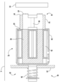
도 2는 본 발명의 실시예에 따른 비-제동 상태의 전자기 안전 트리거의 단면도이다;
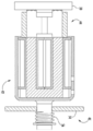
도 3은 본 발명의 실시예에 따른 제동 상태의 전자기 안전 트리거의 측면도이다;
도 4는 본 발명의 실시예에 따라 제동 위치에 있는 전자기 안전 트리거의 단면도이며 작동 상태에 있다; 그리고
도 5는 본 발명의 실시예에 따라 제동 위치에 있는 전자기 안전 트리거의 단면도이며 제동 상태로부터 비-제동 상태로의 상태 전이 중에 있다.The embodiments and other features, advantages and disclosures contained in the present application and the manner of attaining them will be apparent and the invention will be further understood by reference to the following description of various exemplary embodiments of the invention taken in conjunction with the accompanying drawings Will be better understood, where: < RTI ID = 0.0 >
1 is a schematic diagram of an elevator system employing a mechanical governor;
2 is a cross-sectional view of an electromagnetic safety trigger in a non-braking state according to an embodiment of the present invention;
3 is a side view of an electromagnetic safety trigger in a braking state according to an embodiment of the present invention;
Figure 4 is a cross-sectional view of the electromagnetic safety trigger in the braking position and in an operating state according to an embodiment of the present invention; And
Figure 5 is a cross-sectional view of an electromagnetic safety trigger in a braking position in accordance with an embodiment of the present invention and during a state transition from a braking state to a non-braking state.
본 발명의 원리들의 이해를 촉진하는 목적들을 위해, 도면들에 예시된 실시예들에 대한 참조가 이루어질 것이며, 그리고 특정 언어가 동일한 것을 설명하기 위해 사용될 것이다. 그럼에도 불구하고 그렇게 함으로써 본 발명의 범위의 어떤 제한도 의도되지 않는다는 것이 이해될 것이다.For purposes of promoting an understanding of the principles of the invention, reference will be made to the embodiments illustrated in the drawings, and specific language will be used to explain the same. It will nevertheless be understood that no limitation of the scope of the invention is thereby intended.
도 1은 일반적으로 10으로 표시되는, 엘리베이터 시스템을 도시한다. 엘리베이터 시스템(10)은 케이블들(12), 카 프레임(14), 카(16), 롤러 가이드들(18), 가이드 레일들(20), 조속기(22), 안전장치들(24), 연결장치들(26), 레버들(28) 및 리프트 로드들(30)을 포함한다. 조속기(22)는 조속기 시브(a governor sheave)(32), 로프 고리(34), 및 텐셔닝 시브(tensioning sheave)(36)를 포함한다. 케이블들(12)은 승강로 내부 카 프레임(14) 및 균형추(도 1에 미도시)에 연결된다. 카 프레임(14)에 부착되는, 카(16)는 통상적으로 승강로의 상부의 기계실에 위치된 엘리베이터 구동장치(미도시)에 의해 케이블들(12)을 통해 카 프레임(14)으로 전달되는 힘에 의해 승강로 위아래로 이동한다. 롤러 가이드들(18)은 카(16)를 가이드 레일(20)을 따라 승강로 위아래로 가이드하기 위해 카 프레임(14)에 부착된다. 조속기 시브(32)는 승강로의 상단에 장착된다. 로프 고리(34)는 조속기 시브(32) 주위에 부분적으로 그리고 텐셔닝 시브(36)(본 실시예에서 승강로의 하단에 위치된) 주위에 부분적으로 싸인다. 로프 고리(34)는 또한 레버(28)로 엘리베이터 카(16)에 연결되어, 조속기 시브(32)의 각속도가 엘리베이터 카(16)의 속도와 직접 관련됨을 보장한다.Figure 1 shows an elevator system, generally indicated at 10. The elevator system 10 includes a plurality of cables 12, a
도 1에 도시된 엘리베이터 시스템(10)에서, 조속기(22), 기계실에 위치된 전기 기계 브레이크(미도시), 및 안전장치들(24)은 그것이 승강로 내부를 이동할 때 카(16)가 설정된 속도를 초과하는 경우 엘리베이터 카(16)를 정지시키도록 작동한다. 카(16)가 과속 상태에 이르는 경우, 조속기(22)는 먼저 스위치를 체결하도록 트리거되며, 이는 결과적으로 엘리베이터 구동장치의 전원을 차단하고 브레이크를 드롭하여 구동 시브의 움직임을 저지하고 그렇게 함으로써 카(16)의 움직임을 저지한다. 그러나, 케이블들(12)이 파열되거나 카(16)가 그 외 브레이크에 의해 영향을 받지 않는 자유 낙하 상태를 경험하면, 조속기(22)는 안전장치들(24)을 작동시켜 카(16)의 움직임을 저지할 수 있다. 브레이크를 드롭하기 위해 스위치를 체결하는 것에 추가하여, 조속기(22)는 또한 조속기 로프(34)를 파지하는 클러칭 디바이스(clutching device)를 해제한다. 조속기 로프(34)는 기계적 연결장치들(26), 레버들(28), 및 리프트 로드들(30)을 통해 안전장치들(24)에 연결된다. 카(16)가 브레이크에 의해 영향을 받지 않는 이의 하강을 계속할 때, 이제 작동 조속기(22)에 의해 이동하는 것이 방지되는, 조속기 로프(34)가 조작 레버(28)를 잡아당긴다. 조작 레버(28)는 리프트 로드들(30)에 연결되는 연결장치들(26)을 이동시킴으로써 안전장치들(24)을 "셋팅"하며, 이 리프트 로드들(30)은 안전장치들(24)이 가이드 레일들(20)을 체결하게 하여 카(16)가 정지하게 한다.1, the
도 2는 정상 작동 상태의 엘리베이터 안전 시스템을 위한 전자기 안전 트리거(40)의 실시예를 도시한다. 전자기 안전 트리거(40)는 전자기 구성요소(42) 및 자기 브레이크(44)를 포함한다. 전자기 구성요소(42)는 하우징(50) 내에 코일(46) 및 코어(48)를 포함한다. 전자기 구성요소(42)는 유지 장치(52)를 더 포함한다. 도시된 실시예에서, 유지 장치(52)는 하우징 벽(54) 및 적어도 하나의 리셋팅 스프링(56)을 포함한다. 적어도 하나의 리셋팅 스프링(56)은 전자기 구성요소(42)를 축(A)에 평행한 방향으로 이동시키도록 구성된다. 실시예에서, 하우징 벽(54)은 가요성이고 전자기 구성요소(42)를 축(A)에 평행한 방향으로 이동시키도록 구성될 수 있다. 그러한 실시예에서, 적어도 하나의 리셋팅 스프링(56)은 요구되지 않을 수 있다. 자기 브레이크(44)는 제1 단부(60)를 갖는 홀더(58) 및 제2 단부(64) 상에 배치된 브레이크 부분(62)을 포함한다. 자석(66)이 홀더(58) 내에 배치되며, 그리고 비-체결 위치에서 전자기 구성요소(42)에 그리고 체결 위치에서 시스템의 금속 구성요소(예를 들어, 가이드 레일들(20))에 자기 브레이크(44)를 자기적으로 결합하도록 구성된다.2 shows an embodiment of an
예를 들어, 비-체결 위치에서, 자기 브레이크(44)는 코어(48)를 통해 전자기 구성요소(42)로 유인되고 홀딩된다. 적어도 하나의 리셋팅 스프링(56)은 정상 작동 상태(즉, 비-체결 위치)에 전자기 구성요소(42)를 홀딩하도록 작동된다. 적어도 하나의 리셋팅 스프링(56)은 자기 브레이크(44) 및 가이드 레일들(20) 간 인력이 적어도 하나의 리셋팅 스프링(56)에 의해 제공되는 유지력보다 훨씬 더 작도록 미리 설정된 장력을 포함한다.For example, in the non-fastening position, the
엘리베이터 카(16)의 하향으로의 과속도 상태 시, 전자기 구성요소(42)는 도 3 및 도 4에 도시된 바와 같이 자기 브레이크(44)를 가이드 레일(20)을 향해 나아가게 한다. 결과적으로, 안전장치(24)는 상대 운동이 가이드 레일(20)에 끼워진 자기 브레이크(44)에 의해 생성될 때, 안전장치(24) 및 자기 브레이크(44)에 작동가능하게 결합된 작은 연결 바(66)에 의해 상향으로 밀어진다.In an overspeed condition of the
도 5는 제동 상태로부터 비-제동 상태로의 전이 상태의 전자기 안전 트리거(40)를 도시한다. 카(16)가 정지된 후, 카(16)는 자기 브레이크(44) 및 전자기 구성요소(42)가 실질적으로 얼라인될 때까지 이동의 반대 방향으로 이동된다. 역전류는 전자기 구성요소(42)가 적어도 하나의 리셋팅 스프링(56)의 스프링력을 극복하고 자기 브레이크(44)를 향해 이동하도록 전자기 구성요소(42)에 동력을 공급한다. 전자기 구성요소(42) 및 자기 브레이크(44)가 완전히 체결될 때, 자기 브레이크(44) 및 레일(20) 간 자기력은 자기 회로의 변화로 인해 상당히 감소된다. 이와 같이, 적어도 하나의 리셋팅 스프링(56)에 의해 생성된 힘은 정상 작동 상태(즉 비-체결 위치, 도 2 참조)로 복귀시키기 위해 자기 브레이크(44) 및 전자기 구성요소(42)를 함께 끌어당길 수 있다.5 shows the
엘리베이터 시스템(10)에 사용되고 있는 전자기 안전 트리거(40)의 실시예가 도시되지만, 전자기 안전 트리거(40)가 임의의 넓은 작동 범위 애플리케이션, 이를테면 두 개의 비-제한적인 예를 예로 들면 회전 배치 및 직선 배치 기계들에 적합할 수 있다는 것이 이해될 것이다.Although an embodiment of the
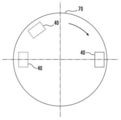
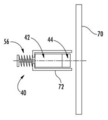
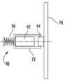
예를 들어, 도 6 내지 도 8은 회전 배치 기계(70)와 전자기 안전 트리거(40)를 도시한다. 정적 하우징 내에 배치되고, 회전 배치 기계(70)에 인접하게 위치된, 하나 이상의 전자기 안전 트리거(40)가 도시된다. 자기 브레이크(44)가 회전 배치 기계(70)를 완전히 체결하도록 추진될 때, 도 8에 도시된 바와 같이, 자기 브레이크(44)의 부분이 회전 배치 기계(70)의 회전을 저지하도록 정적 하우징(72) 내에 남아 있다.For example, Figs. 6-8 illustrate a
따라서 본 실시예들이 재설정된 상태 동안 시스템의 금속 구성요소로부터 자기 브레이크(44)를 체결해제하기에 충분한 힘을 발생시킬 수 있는 유지 장치(52)를 갖는 전자기 안전 트리거(40)를 포함한다는 것이 이해될 것이다.It is therefore understood that the embodiments include an
본 발명이 도면들 및 앞에서의 설명에서 상세하게 예시되고 설명되었지만, 동일한 것이 성격상 예시적인 것으로 그리고 제한적이지 않은 것으로 간주될 것이며, 단지 소정의 실시예들이 도시되고 설명되었다는 것이 이해되고 발명의 사상 내에 들어가는 모든 변경 및 변형이 보호되는 것이 바람직하다.While the invention has been illustrated and described in detail in the drawings and foregoing description, it is to be understood that the same is by way of illustration and not of limitation, and that it is understood that only certain embodiments have been shown and described, It is desirable that all changes and modifications entered are protected.
Claims (18)
상기 카 상에 배치되고 비-제동 상태로부터 제동 상태로 이동될 때 상기 가이드레일들 중 하나 가까이에 고정되도록 적응되는 안전 브레이크;
상기 안전 브레이크에 작동가능하게 결합된 로드로서, 상기 안전 브레이크를 비-분열 상태 및 제동 상태 사이에서 이동시키도록 구성된, 상기 로드;
상기 로드에 작동가능하게 결합되고 상기 가이드레일에 인접하게 배치된 자기 브레이크(magnetic brake)로서, 레일-체결 위치 및 레일-비-체결 위치 사이를 이동하도록 구성되고, 상기 레일-체결 위치에 있을 때, 상기 카의 움직임과 동시에, 그렇게 함으로써 상기 안전 브레이크를 상기 비-제동 상태로부터 상기 제동 상태로 이동시키기 위한 방향으로 상기 로드를 이동시키는, 상기 자기 브레이크; 및
전자기 구성요소로서, 리셋팅 신호의 수신시 상기 자기 브레이크를 상기 레일-체결 위치로부터 상기 레일-비-체결 위치로 이동시키도록 구성된, 상기 전자기 구성요소를 포함하는, 제동 디바이스.A braking device operable selectively for an elevator system comprising a car and a plurality of guide rails,
A safety brake disposed on said car and adapted to be secured near one of said guide rails when moved from a non-braking state to a braking state;
A rod operatively coupled to the safety brake, the rod configured to move the safety brake between a non-disengaged state and a braked state;
A magnetic brake operatively coupled to the rod and disposed adjacent to the guide rail, the magnetic brake configured to move between a rail-engaged position and a rail-non-engaged position, wherein when in the rail- So as to move the rod in a direction for moving the safety brake from the non-braking state to the braking state simultaneously with the movement of the car; And
The electromagnetic component being configured to move the magnetic brake from the rail-engaged position to the rail-non-engaged position upon receipt of a resetting signal.
상기 전자기 구성요소와 전기적으로 통신하는 안전 제어기로서, 트리거 신호 및 상기 리셋팅 신호를 송신하도록 구성된, 상기 안전 제어기를 더 포함하는, 제동 디바이스.The method according to claim 1,
And a safety controller in electrical communication with the electromagnetic component, the safety controller configured to transmit a trigger signal and the reset signal.
기계 상에 배치되고 비-제동 상태로부터 제동 상태로 이동될 때 상기 기계의 움직임을 저지하도록 적응된 안전 브레이크;
상기 기계에 인접하게 배치된 자기 브레이크로서, 체결 위치 및 비-체결 위치 사이를 이동하도록 구성되고, 상기 체결 위치에 있을 때 상기 기계의 움직임과 동시에, 그렇게 함으로써 상기 안전 브레이크를 상기 비-제동 상태로부터 상기 제동 상태로 이동시키도록 이동하는, 상기 자기 브레이크; 및
리셋팅 신호의 수신시 상기 자기 브레이크를 상기 체결 위치로부터 상기 비-체결 위치로 이동시키도록 구성된 전자기 구성요소를 포함하는, 자기 제동 시스템.A selectively actuatable magnetic braking system comprising:
A safety brake disposed on the machine and adapted to inhibit movement of the machine when moved from a non-braking state to a braking state;
A magnetic brake disposed adjacent to the machine and configured to move between a locked position and a non-locked position and coincide with movement of the machine when in the locked position, thereby causing the safety brake to move from the non- And moves to move to the braking state; And
And an electromagnetic component configured to move the magnetic brake from the engaged position to the non-engaged position upon receipt of a reset signal.
상기 전자기 구성요소와 전기적으로 통신하는 안전 제어기로서, 트리거 신호 및 상기 리셋팅 신호를 송신하도록 구성된, 상기 안전 제어기를 더 포함하는, 자기 제동 시스템.The method of claim 10,
And a safety controller in electrical communication with the electromagnetic component, the safety controller being configured to transmit a trigger signal and the reset signal.
Applications Claiming Priority (2)
| Application Number | Priority Date | Filing Date | Title |
|---|---|---|---|
| US201562186635P | 2015-06-30 | 2015-06-30 | |
| US62/186,635 | 2015-06-30 |
Publications (2)
| Publication Number | Publication Date |
|---|---|
| KR20170003473A true KR20170003473A (en) | 2017-01-09 |
| KR102616688B1 KR102616688B1 (en) | 2023-12-21 |
Family
ID=56345028
Family Applications (1)
| Application Number | Title | Priority Date | Filing Date |
|---|---|---|---|
| KR1020160082315A Active KR102616688B1 (en) | 2015-06-30 | 2016-06-30 | Electromagnetic safety trigger |
Country Status (5)
| Country | Link |
|---|---|
| US (1) | US10654686B2 (en) |
| EP (1) | EP3112306B1 (en) |
| KR (1) | KR102616688B1 (en) |
| CN (1) | CN106395544B (en) |
| ES (1) | ES2790658T3 (en) |
Families Citing this family (31)
| Publication number | Priority date | Publication date | Assignee | Title |
|---|---|---|---|---|
| US10494227B2 (en) * | 2014-06-12 | 2019-12-03 | Otis Elevator Company | Braking system resetting mechanism for a hoisted structure |
| US10618776B2 (en) * | 2014-06-12 | 2020-04-14 | Otis Elevator Company | Brake member actuation mechanism |
| WO2017023926A1 (en) * | 2015-08-04 | 2017-02-09 | Otis Elevator Company | Device and method for actuating an elevator safety brake |
| WO2017087976A1 (en) * | 2015-11-20 | 2017-05-26 | Otis Elevator Company | Housing assembly for a safety actuation device |
| WO2017087978A1 (en) * | 2015-11-20 | 2017-05-26 | Otis Elevator Company | Electronic safety actuator |
| US10584014B2 (en) * | 2015-12-07 | 2020-03-10 | Otis Elevator Company | Robust electrical safety actuation module |
| EP3210926B1 (en) * | 2016-02-23 | 2020-01-01 | Otis Elevator Company | Elevator service panel |
| US10112803B2 (en) * | 2016-04-01 | 2018-10-30 | Otis Elevator Company | Protection assembly for elevator braking assembly speed sensing device and method |
| US20180162693A1 (en) * | 2016-12-13 | 2018-06-14 | Otis Elevator Company | Speed detection means for elevator or counterweight |
| US10569993B2 (en) * | 2017-03-29 | 2020-02-25 | Otis Elevator Company | Safety brake actuation mechanism for a hoisted structure |
| US10562739B2 (en) * | 2017-08-25 | 2020-02-18 | Otis Elevator Company | Synchronized electronic safety actuator |
| EP3564171B1 (en) * | 2018-04-30 | 2021-04-14 | Otis Elevator Company | Elevator safety gear actuation device |
| US11078045B2 (en) * | 2018-05-15 | 2021-08-03 | Otis Elevator Company | Electronic safety actuator for lifting a safety wedge of an elevator |
| US11053097B2 (en) * | 2018-07-26 | 2021-07-06 | Otis Elevator Company | Magnet assembly for an electronic safety brake actuator (ESBA) |
| EP3608273B1 (en) | 2018-08-10 | 2022-09-28 | Otis Elevator Company | Elevator safety gear actuation device |
| US11242222B2 (en) * | 2018-10-26 | 2022-02-08 | Otis Elevator Company | Elevator braking device mechanism |
| US11104545B2 (en) * | 2018-12-10 | 2021-08-31 | Otis Elevator Company | Elevator safety actuator systems |
| EP3670414B1 (en) * | 2018-12-20 | 2023-06-14 | KONE Corporation | An elevator safety gear trigger and reset system |
| EP3677534B1 (en) * | 2019-01-02 | 2021-07-21 | Otis Elevator Company | Elevator safety device actuator |
| CN114787065B (en) * | 2019-12-12 | 2025-04-01 | 因温特奥股份公司 | Braking device for braking a travel body displaceable along a guide rail in a displacement direction, for example with a wedge-shaped brake element |
| US11479443B2 (en) * | 2020-02-18 | 2022-10-25 | Otis Elevator Company | Elevator brake assembly with electromagnet assembly and permanent magnet assembly that engage one another |
| US11603288B2 (en) * | 2020-06-29 | 2023-03-14 | Otis Elevator Company | Magnet assemblies of electromechanical actuators for elevator systems |
| CN112573323B (en) * | 2020-12-18 | 2022-06-24 | 施密特电梯有限公司 | High security performance big goods ladder |
| CN113148803B (en) * | 2021-03-10 | 2023-04-07 | 宁波奥德普电梯部件有限公司 | Electronic safety gear trigger of elevator |
| EP4140931B1 (en) * | 2021-08-23 | 2025-07-30 | Otis Elevator Company | Safety brake system |
| EP4541749A1 (en) * | 2021-11-05 | 2025-04-23 | Otis Elevator Company | Safety brake system |
| CN114426235B (en) * | 2021-12-31 | 2024-03-19 | 宁波奥德普电梯部件有限公司 | Electronic safety gear trigger for elevator |
| WO2023187231A1 (en) * | 2022-05-26 | 2023-10-05 | Dynatech, Dynamics & Technology, S.L. | Compact electromechanical activation system for a lift safety device |
| EP4289776B1 (en) * | 2022-06-09 | 2026-01-28 | Otis Elevator Company | Resetting a safety actuator in an elevator system |
| ES3055690T3 (en) * | 2022-08-31 | 2026-02-13 | Otis Elevator Co | Frictionless safety brake actuator |
| US12643769B2 (en) * | 2024-10-22 | 2026-06-02 | Otis Elevator Company | Electromechanical safety actuation of elevator governors |
Citations (1)
| Publication number | Priority date | Publication date | Assignee | Title |
|---|---|---|---|---|
| WO2006054328A1 (en) * | 2004-11-16 | 2006-05-26 | Mitsubishi Denki Kabushiki Kaisha | Safety device for elevator |
Family Cites Families (26)
| Publication number | Priority date | Publication date | Assignee | Title |
|---|---|---|---|---|
| FI92812C (en) | 1992-07-07 | 1995-01-10 | Kone Oy | Arrangement with safety device |
| US6161653A (en) | 1998-12-22 | 2000-12-19 | Otis Elevator Company | Ropeless governor mechanism for an elevator car |
| US6173813B1 (en) | 1998-12-23 | 2001-01-16 | Otis Elevator Company | Electronic control for an elevator braking system |
| JP2004262652A (en) | 2002-09-23 | 2004-09-24 | Inventio Ag | Safety device for elevator |
| MY135853A (en) | 2003-02-04 | 2008-07-31 | Inventio Ag | Safety device for an elevator |
| ATE491662T1 (en) | 2003-10-07 | 2011-01-15 | Otis Elevator Co | REMOTE-RESETABLE CABLE-LESS EMERGENCY STOP DEVICE FOR AN ELEVATOR |
| JP4410248B2 (en) * | 2004-03-15 | 2010-02-03 | 三菱電機株式会社 | Elevator braking device |
| WO2005102898A1 (en) * | 2004-03-30 | 2005-11-03 | Mitsubishi Denki Kabushiki Kaisha | Control device of elevator |
| CN100537389C (en) * | 2004-04-20 | 2009-09-09 | 三菱电机株式会社 | Emergency stop system for elevator |
| JP4566994B2 (en) | 2004-04-30 | 2010-10-20 | 三菱電機株式会社 | Elevator braking system |
| CA2544664C (en) | 2004-05-25 | 2011-06-14 | Mitsubishi Denki Kabushiki Kaisha | Safety device for an elevator |
| WO2006062503A1 (en) * | 2004-12-03 | 2006-06-15 | Otis Elevator Company | Safety device for use in an elevator system |
| BRPI0601926B1 (en) | 2005-06-17 | 2018-06-12 | Inventio Aktiengesellschaft | BRAKE PARACHUTE DEVICE |
| ATE504532T1 (en) * | 2006-11-08 | 2011-04-15 | Otis Elevator Co | WINDING BRAKE DEVICE |
| EP2408703B1 (en) | 2009-03-16 | 2016-11-09 | Otis Elevator Company | Electromagnetic safety trigger |
| WO2011146073A1 (en) | 2010-05-21 | 2011-11-24 | Otis Elevator Company | Elevator holding and safety brake engagement mechanism |
| BR112013015237B1 (en) | 2010-12-17 | 2022-06-28 | Inventio Ag | DEVICE AND PROCESS FOR ACTIVATING AND RESTORING AN INTERCEPTOR DEVICE |
| US9169104B2 (en) | 2010-12-17 | 2015-10-27 | Inventio Ag | Activating a safety gear |
| WO2013023944A1 (en) | 2011-08-16 | 2013-02-21 | Inventio Ag | Triggering of a lift brake in an emergency situation |
| WO2013070234A1 (en) | 2011-11-11 | 2013-05-16 | Otis Elevator Company | Elevator braking device with automatic reset feature |
| BR112014015079A2 (en) | 2011-12-21 | 2017-06-13 | Inventio Ag | lift brake actuator |
| CN102923547B (en) | 2012-11-05 | 2014-12-03 | 江苏大学 | Auxiliary braking device of cordless elevator and control method thereof |
| US9688512B2 (en) * | 2012-11-15 | 2017-06-27 | Otis Elevator Company | Elevator brake |
| US10781075B2 (en) | 2013-09-30 | 2020-09-22 | Otis Elevator Company | Emergency safety actuator for an elevator |
| WO2017087978A1 (en) | 2015-11-20 | 2017-05-26 | Otis Elevator Company | Electronic safety actuator |
| US10584014B2 (en) | 2015-12-07 | 2020-03-10 | Otis Elevator Company | Robust electrical safety actuation module |
-
2016
- 2016-06-10 US US15/179,281 patent/US10654686B2/en active Active
- 2016-06-30 ES ES16177329T patent/ES2790658T3/en active Active
- 2016-06-30 CN CN201610509130.7A patent/CN106395544B/en active Active
- 2016-06-30 KR KR1020160082315A patent/KR102616688B1/en active Active
- 2016-06-30 EP EP16177329.6A patent/EP3112306B1/en active Active
Patent Citations (1)
| Publication number | Priority date | Publication date | Assignee | Title |
|---|---|---|---|---|
| WO2006054328A1 (en) * | 2004-11-16 | 2006-05-26 | Mitsubishi Denki Kabushiki Kaisha | Safety device for elevator |
Also Published As
| Publication number | Publication date |
|---|---|
| EP3112306B1 (en) | 2020-04-29 |
| US10654686B2 (en) | 2020-05-19 |
| US20170001835A1 (en) | 2017-01-05 |
| EP3112306A1 (en) | 2017-01-04 |
| ES2790658T3 (en) | 2020-10-28 |
| CN106395544B (en) | 2020-03-31 |
| CN106395544A (en) | 2017-02-15 |
| KR102616688B1 (en) | 2023-12-21 |
Similar Documents
| Publication | Publication Date | Title |
|---|---|---|
| KR102616688B1 (en) | Electromagnetic safety trigger | |
| EP3377434B1 (en) | Electronic safety actuator | |
| EP3141511B1 (en) | Housing assembly for a safety actuation device | |
| CN108367892B (en) | Robust Electrical Safety Actuation Module | |
| EP3147246B1 (en) | Actuator assembly for an elevator governor system and method | |
| EP3331798B1 (en) | Device and method for actuating an elevator safety brake | |
| US11078045B2 (en) | Electronic safety actuator for lifting a safety wedge of an elevator | |
| EP3377433B1 (en) | Housing assembly for a safety actuation device | |
| US11845634B2 (en) | Safety brake device | |
| CN110342367B (en) | Electromagnetic safety trigger | |
| US12214995B2 (en) | Safety brake system | |
| US11858781B2 (en) | Frictionless electronic safety actuator | |
| CN113498399B (en) | Trigger system for safety gear, elevator installation and method for operating an elevator installation | |
| EP4378875A1 (en) | Frictionless safety brake actuator | |
| US11970367B2 (en) | Safety brake actuator |
Legal Events
| Date | Code | Title | Description |
|---|---|---|---|
| PA0109 | Patent application |
Patent event code: PA01091R01D Comment text: Patent Application Patent event date: 20160630 |
|
| PG1501 | Laying open of application | ||
| A201 | Request for examination | ||
| PA0201 | Request for examination |
Patent event code: PA02012R01D Patent event date: 20210622 Comment text: Request for Examination of Application Patent event code: PA02011R01I Patent event date: 20160630 Comment text: Patent Application |
|
| E902 | Notification of reason for refusal | ||
| PE0902 | Notice of grounds for rejection |
Comment text: Notification of reason for refusal Patent event date: 20230328 Patent event code: PE09021S01D |
|
| E701 | Decision to grant or registration of patent right | ||
| PE0701 | Decision of registration |
Patent event code: PE07011S01D Comment text: Decision to Grant Registration Patent event date: 20231004 |
|
| GRNT | Written decision to grant | ||
| PR0701 | Registration of establishment |
Comment text: Registration of Establishment Patent event date: 20231218 Patent event code: PR07011E01D |
|
| PR1002 | Payment of registration fee |
Payment date: 20231219 End annual number: 3 Start annual number: 1 |
|
| PG1601 | Publication of registration |