KR20170009902A - Layered construction of metallic materials - Google Patents
Layered construction of metallic materials Download PDFInfo
- Publication number
- KR20170009902A KR20170009902A KR1020167034840A KR20167034840A KR20170009902A KR 20170009902 A KR20170009902 A KR 20170009902A KR 1020167034840 A KR1020167034840 A KR 1020167034840A KR 20167034840 A KR20167034840 A KR 20167034840A KR 20170009902 A KR20170009902 A KR 20170009902A
- Authority
- KR
- South Korea
- Prior art keywords
- layer
- alloy
- substrate
- micrometers
- metal
- Prior art date
- Legal status (The legal status is an assumption and is not a legal conclusion. Google has not performed a legal analysis and makes no representation as to the accuracy of the status listed.)
- Granted
Links
Images


Classifications
-
- B—PERFORMING OPERATIONS; TRANSPORTING
- B22—CASTING; POWDER METALLURGY
- B22D—CASTING OF METALS; CASTING OF OTHER SUBSTANCES BY THE SAME PROCESSES OR DEVICES
- B22D19/00—Casting in, on, or around objects which form part of the product
-
- B—PERFORMING OPERATIONS; TRANSPORTING
- B22—CASTING; POWDER METALLURGY
- B22D—CASTING OF METALS; CASTING OF OTHER SUBSTANCES BY THE SAME PROCESSES OR DEVICES
- B22D25/00—Special casting characterised by the nature of the product
-
- B—PERFORMING OPERATIONS; TRANSPORTING
- B22—CASTING; POWDER METALLURGY
- B22F—WORKING METALLIC POWDER; MANUFACTURE OF ARTICLES FROM METALLIC POWDER; MAKING METALLIC POWDER; APPARATUS OR DEVICES SPECIALLY ADAPTED FOR METALLIC POWDER
- B22F10/00—Additive manufacturing of workpieces or articles from metallic powder
- B22F10/20—Direct sintering or melting
- B22F10/28—Powder bed fusion, e.g. selective laser melting [SLM] or electron beam melting [EBM]
-
- B—PERFORMING OPERATIONS; TRANSPORTING
- B22—CASTING; POWDER METALLURGY
- B22F—WORKING METALLIC POWDER; MANUFACTURE OF ARTICLES FROM METALLIC POWDER; MAKING METALLIC POWDER; APPARATUS OR DEVICES SPECIALLY ADAPTED FOR METALLIC POWDER
- B22F10/00—Additive manufacturing of workpieces or articles from metallic powder
- B22F10/60—Treatment of workpieces or articles after build-up
- B22F10/66—Treatment of workpieces or articles after build-up by mechanical means
-
- B—PERFORMING OPERATIONS; TRANSPORTING
- B22—CASTING; POWDER METALLURGY
- B22F—WORKING METALLIC POWDER; MANUFACTURE OF ARTICLES FROM METALLIC POWDER; MAKING METALLIC POWDER; APPARATUS OR DEVICES SPECIALLY ADAPTED FOR METALLIC POWDER
- B22F12/00—Apparatus or devices specially adapted for additive manufacturing; Auxiliary means for additive manufacturing; Combinations of additive manufacturing apparatus or devices with other processing apparatus or devices
- B22F12/30—Platforms or substrates
-
- B—PERFORMING OPERATIONS; TRANSPORTING
- B22—CASTING; POWDER METALLURGY
- B22F—WORKING METALLIC POWDER; MANUFACTURE OF ARTICLES FROM METALLIC POWDER; MAKING METALLIC POWDER; APPARATUS OR DEVICES SPECIALLY ADAPTED FOR METALLIC POWDER
- B22F7/00—Manufacture of composite layers, workpieces, or articles, comprising metallic powder, by sintering the powder, with or without compacting wherein at least one part is obtained by sintering or compression
- B22F7/02—Manufacture of composite layers, workpieces, or articles, comprising metallic powder, by sintering the powder, with or without compacting wherein at least one part is obtained by sintering or compression of composite layers
-
- B—PERFORMING OPERATIONS; TRANSPORTING
- B32—LAYERED PRODUCTS
- B32B—LAYERED PRODUCTS, i.e. PRODUCTS BUILT-UP OF STRATA OF FLAT OR NON-FLAT, e.g. CELLULAR OR HONEYCOMB, FORM
- B32B15/00—Layered products comprising a layer of metal
- B32B15/01—Layered products comprising a layer of metal all layers being exclusively metallic
-
- B—PERFORMING OPERATIONS; TRANSPORTING
- B32—LAYERED PRODUCTS
- B32B—LAYERED PRODUCTS, i.e. PRODUCTS BUILT-UP OF STRATA OF FLAT OR NON-FLAT, e.g. CELLULAR OR HONEYCOMB, FORM
- B32B5/00—Layered products characterised by the non- homogeneity or physical structure, i.e. comprising a fibrous, filamentary, particulate or foam layer; Layered products characterised by having a layer differing constitutionally or physically in different parts
- B32B5/16—Layered products characterised by the non- homogeneity or physical structure, i.e. comprising a fibrous, filamentary, particulate or foam layer; Layered products characterised by having a layer differing constitutionally or physically in different parts characterised by features of a layer formed of particles, e.g. chips, powder or granules
-
- C—CHEMISTRY; METALLURGY
- C22—METALLURGY; FERROUS OR NON-FERROUS ALLOYS; TREATMENT OF ALLOYS OR NON-FERROUS METALS
- C22C—ALLOYS
- C22C1/00—Making non-ferrous alloys
- C22C1/02—Making non-ferrous alloys by melting
-
- C—CHEMISTRY; METALLURGY
- C22—METALLURGY; FERROUS OR NON-FERROUS ALLOYS; TREATMENT OF ALLOYS OR NON-FERROUS METALS
- C22C—ALLOYS
- C22C38/00—Ferrous alloys, e.g. steel alloys
- C22C38/02—Ferrous alloys, e.g. steel alloys containing silicon
-
- C—CHEMISTRY; METALLURGY
- C22—METALLURGY; FERROUS OR NON-FERROUS ALLOYS; TREATMENT OF ALLOYS OR NON-FERROUS METALS
- C22C—ALLOYS
- C22C38/00—Ferrous alloys, e.g. steel alloys
- C22C38/04—Ferrous alloys, e.g. steel alloys containing manganese
-
- C—CHEMISTRY; METALLURGY
- C22—METALLURGY; FERROUS OR NON-FERROUS ALLOYS; TREATMENT OF ALLOYS OR NON-FERROUS METALS
- C22C—ALLOYS
- C22C38/00—Ferrous alloys, e.g. steel alloys
- C22C38/18—Ferrous alloys, e.g. steel alloys containing chromium
- C22C38/22—Ferrous alloys, e.g. steel alloys containing chromium with molybdenum or tungsten
-
- C—CHEMISTRY; METALLURGY
- C22—METALLURGY; FERROUS OR NON-FERROUS ALLOYS; TREATMENT OF ALLOYS OR NON-FERROUS METALS
- C22C—ALLOYS
- C22C38/00—Ferrous alloys, e.g. steel alloys
- C22C38/18—Ferrous alloys, e.g. steel alloys containing chromium
- C22C38/26—Ferrous alloys, e.g. steel alloys containing chromium with niobium or tantalum
-
- C—CHEMISTRY; METALLURGY
- C22—METALLURGY; FERROUS OR NON-FERROUS ALLOYS; TREATMENT OF ALLOYS OR NON-FERROUS METALS
- C22C—ALLOYS
- C22C38/00—Ferrous alloys, e.g. steel alloys
- C22C38/18—Ferrous alloys, e.g. steel alloys containing chromium
- C22C38/32—Ferrous alloys, e.g. steel alloys containing chromium with boron
-
- C—CHEMISTRY; METALLURGY
- C22—METALLURGY; FERROUS OR NON-FERROUS ALLOYS; TREATMENT OF ALLOYS OR NON-FERROUS METALS
- C22C—ALLOYS
- C22C38/00—Ferrous alloys, e.g. steel alloys
- C22C38/18—Ferrous alloys, e.g. steel alloys containing chromium
- C22C38/34—Ferrous alloys, e.g. steel alloys containing chromium with more than 1.5% by weight of silicon
-
- C—CHEMISTRY; METALLURGY
- C22—METALLURGY; FERROUS OR NON-FERROUS ALLOYS; TREATMENT OF ALLOYS OR NON-FERROUS METALS
- C22C—ALLOYS
- C22C38/00—Ferrous alloys, e.g. steel alloys
- C22C38/18—Ferrous alloys, e.g. steel alloys containing chromium
- C22C38/36—Ferrous alloys, e.g. steel alloys containing chromium with more than 1.7% by weight of carbon
-
- C—CHEMISTRY; METALLURGY
- C22—METALLURGY; FERROUS OR NON-FERROUS ALLOYS; TREATMENT OF ALLOYS OR NON-FERROUS METALS
- C22C—ALLOYS
- C22C38/00—Ferrous alloys, e.g. steel alloys
- C22C38/18—Ferrous alloys, e.g. steel alloys containing chromium
- C22C38/38—Ferrous alloys, e.g. steel alloys containing chromium with more than 1.5% by weight of manganese
-
- B—PERFORMING OPERATIONS; TRANSPORTING
- B22—CASTING; POWDER METALLURGY
- B22F—WORKING METALLIC POWDER; MANUFACTURE OF ARTICLES FROM METALLIC POWDER; MAKING METALLIC POWDER; APPARATUS OR DEVICES SPECIALLY ADAPTED FOR METALLIC POWDER
- B22F7/00—Manufacture of composite layers, workpieces, or articles, comprising metallic powder, by sintering the powder, with or without compacting wherein at least one part is obtained by sintering or compression
- B22F7/02—Manufacture of composite layers, workpieces, or articles, comprising metallic powder, by sintering the powder, with or without compacting wherein at least one part is obtained by sintering or compression of composite layers
- B22F7/04—Manufacture of composite layers, workpieces, or articles, comprising metallic powder, by sintering the powder, with or without compacting wherein at least one part is obtained by sintering or compression of composite layers with one or more layers not made from powder, e.g. made from solid metal
- B22F2007/042—Manufacture of composite layers, workpieces, or articles, comprising metallic powder, by sintering the powder, with or without compacting wherein at least one part is obtained by sintering or compression of composite layers with one or more layers not made from powder, e.g. made from solid metal characterised by the layer forming method
-
- B—PERFORMING OPERATIONS; TRANSPORTING
- B22—CASTING; POWDER METALLURGY
- B22F—WORKING METALLIC POWDER; MANUFACTURE OF ARTICLES FROM METALLIC POWDER; MAKING METALLIC POWDER; APPARATUS OR DEVICES SPECIALLY ADAPTED FOR METALLIC POWDER
- B22F2998/00—Supplementary information concerning processes or compositions relating to powder metallurgy
- B22F2998/10—Processes characterised by the sequence of their steps
-
- B—PERFORMING OPERATIONS; TRANSPORTING
- B22—CASTING; POWDER METALLURGY
- B22F—WORKING METALLIC POWDER; MANUFACTURE OF ARTICLES FROM METALLIC POWDER; MAKING METALLIC POWDER; APPARATUS OR DEVICES SPECIALLY ADAPTED FOR METALLIC POWDER
- B22F2999/00—Aspects linked to processes or compositions used in powder metallurgy
-
- B—PERFORMING OPERATIONS; TRANSPORTING
- B33—ADDITIVE MANUFACTURING TECHNOLOGY
- B33Y—ADDITIVE MANUFACTURING, i.e. MANUFACTURING OF THREE-DIMENSIONAL [3D] OBJECTS BY ADDITIVE DEPOSITION, ADDITIVE AGGLOMERATION OR ADDITIVE LAYERING, e.g. BY 3D PRINTING, STEREOLITHOGRAPHY OR SELECTIVE LASER SINTERING
- B33Y10/00—Processes of additive manufacturing
-
- Y—GENERAL TAGGING OF NEW TECHNOLOGICAL DEVELOPMENTS; GENERAL TAGGING OF CROSS-SECTIONAL TECHNOLOGIES SPANNING OVER SEVERAL SECTIONS OF THE IPC; TECHNICAL SUBJECTS COVERED BY FORMER USPC CROSS-REFERENCE ART COLLECTIONS [XRACs] AND DIGESTS
- Y02—TECHNOLOGIES OR APPLICATIONS FOR MITIGATION OR ADAPTATION AGAINST CLIMATE CHANGE
- Y02P—CLIMATE CHANGE MITIGATION TECHNOLOGIES IN THE PRODUCTION OR PROCESSING OF GOODS
- Y02P10/00—Technologies related to metal processing
- Y02P10/25—Process efficiency
Landscapes
- Chemical & Material Sciences (AREA)
- Engineering & Computer Science (AREA)
- Materials Engineering (AREA)
- Mechanical Engineering (AREA)
- Metallurgy (AREA)
- Organic Chemistry (AREA)
- Manufacturing & Machinery (AREA)
- Physics & Mathematics (AREA)
- Plasma & Fusion (AREA)
- Composite Materials (AREA)
- Life Sciences & Earth Sciences (AREA)
- Wood Science & Technology (AREA)
- Other Surface Treatments For Metallic Materials (AREA)
- Powder Metallurgy (AREA)
- Sliding-Contact Bearings (AREA)
- Laser Beam Processing (AREA)
- Laminated Bodies (AREA)
Abstract
본 개시는 기판 상에 금속성 합금의 적층 방식 증착을 위한 합금 및 방법에 관한 것이다. 생성된 증착물은 연관된 내마모성을 가진 비교적 높은 경도의 금속 부품을 제공한다. 금속 부품에 대한 적용은 펌프, 밸브 및/또는 베어링을 포함한다.The present disclosure relates to alloys and methods for deposition-type deposition of metallic alloys on substrates. The resulting deposits provide relatively high hardness metal parts with associated abrasion resistance. Applications to metal parts include pumps, valves and / or bearings.
Description
관련 출원에 대한 상호 참조Cross-reference to related application
이 출원은 2014년 5월 16일에 출원된 미국 가특허출원 일련 번호 61/994,758을 우선권 주장하며, 이 가특허출원 전부를 본원에 참조로 포함한다.This application claims priority to U.S. Provisional Patent Application Serial No. 61 / 994,758, filed May 16, 2014, which is incorporated herein by reference in its entirety.
발명의 분야Field of invention
본 발명은 층별(layerwise) 방식으로 자립형(free-standing) 금속 재료를 제조하기 위한 합금 및 방법에 관한 것이다.The present invention relates to alloys and methods for making free-standing metal materials in a layerwise manner.
철 금속은 드릴 파이프 하드밴딩(drill pipe hardbanding), 채광용 트럭 베드 라이너(mining truck bed liner), 및 보일러 관과 같은 많은 적용에서 코팅물(coating)로서 사용되며, 여기서 코팅물은 비교적 보다 적은 내마모성 부품에 내마모성 및 내마멸성(wear and abrasion resistance)을 제공한다. 이들 코팅물은 HVOF 또는 트윈 와이어 아크 용사(twin-wire arc thermal spray), 및 PTAW 또는 GMAW 용접 오버레이(weld overlay)와 같은 다양한 기술을 통해 기판에 적용될 수 있다.Ferrous metals are used as coatings in many applications, such as drill pipe hardbanding, mining truck bed liners, and boiler tubes, where the coating has relatively few abrasion-resistant parts To provide wear and abrasion resistance. These coatings can be applied to the substrate via a variety of techniques such as HVOF or twin-wire arc thermal spray, and PTAW or GMAW weld overlays.
내마모성 철 금속 코팅물은 일반적으로 재료의 내마모성을 가능하게 하고 기저(underlying) 기판을 보호하는 비교적 높은 표면 경도 및 비교적 저렴한 비용을 특징으로 한다. 내마모성 코팅물로서 사용되는 재료는 기판에 부착되어 원하는 표면 성능을 제공하도록 설계되었으며, 그와 같이 강도 및 인성과 같은 비-표면(non-surface) 특성에 대해 기판에 대체로 의존한다. 내마모성을 위해 사용되는 철 금속 코팅물의 예는 크롬 카바이드, 복합 카바이드(complex carbide), 티탄 카바이드, 바나듐 카바이드, 및 공구 강을 포함한다. Abrasion resistant ferrous metal coatings generally feature relatively high surface hardness and relatively low cost to enable wear resistance of the material and to protect the underlying substrate. The material used as the abrasion resistant coating is designed to be adhered to the substrate to provide the desired surface performance and thus largely depends on the substrate for non-surface properties such as strength and toughness. Examples of ferrous metal coatings used for abrasion resistance include chromium carbide, complex carbide, titanium carbide, vanadium carbide, and tool steel.
층별 공법(layerwise construction)은 본원에서 부품을 성형 가공(fabrication)하기 위해 재료의 층을 적층 방식으로(layer by layer), 빌드 업(build up)하거나, 레이 다운(lay down)하는 공정으로 이해될 수 있다. 층별 공법의 예는 레이저 에너지 원을 사용한 분말 소결(powder bed fusion) (PBF-L), 또는 전자빔 에너지 원을 사용한 분말 소결 (PBF-E), 직접 용착(directed energy deposition) (DED), 접착제 분사(binder jetting) (BJ), 판재 적층(sheet lamination), 재료 압출(material extrusion), 재료 분사(material jetting), 및 액층 광중합(vat photopolymerization)을 포함한다. 금속과 함께 사용되는 주요 층별 공법은 PBF-L, PBF-E, DED 및 BJ를 포함한다. Layerwise construction is understood herein as a process of layer by layer, build up, or lay down a layer of material for fabrication of components. . Examples of layer-by-layer techniques include powder bed fusion (PBF-L) using a laser energy source, powder sintering (PBF-E) using an electron beam energy source, direct energy deposition (DED) binder jetting (BJ), sheet lamination, material extrusion, material jetting, and vat photopolymerization. The major layered processes used with metals include PBF-L, PBF-E, DED and BJ.
층별 공법 공정은 스테인레스 강 합금, 알루미늄 합금, 티탄 합금, 니켈계(nickel-based) 합금, 및 코발트 크롬 합금을 포함한 여러 가지의 연성 금속으로부터 부품을 구축하는 탁월한 능력을 갖는다. 금속에 대한 액체-상 층별 공법 공정, 예컨대 PBF-L, PBF-E, 및 DED에서, 구축 재료(construction material)는 고체 상에서 액체 상 (용융)으로 전이한 다음에, 다시 고체 상 (응고(solidification))으로 전이한다. 용해에 사용되는 에너지 원은 용해될 재료 표면의 비교적 작은 영역에 집중될 수 있으며, 그와 같이 용해되는 재료의 부피를 비교적 작은 부피로 제어할 수 있다. 큰 고체 부피와 접촉하고 있는 작은 용융 부피는 비교적 급속 방식으로 응고하는 능력을 갖는다. 이러한 급속 응고는 단련(wrought) 금속 특성과 비교되는 경우 기계적 특성의 증가 및 결정립 크기 미세화(grain size refinement)의 원인이 된다.The layer-by-layer process has an excellent ability to build parts from a variety of soft metals, including stainless steel alloys, aluminum alloys, titanium alloys, nickel-based alloys, and cobalt chromium alloys. In PBF-L, PBF-E, and DED, the construction material is transferred from the solid phase to the liquid phase (molten) and then solidified (solidification )). The energy source used for dissolution can be concentrated in a relatively small area of the surface of the material to be dissolved and the volume of the dissolving material can be controlled to a relatively small volume. The small molten volume in contact with a large solid volume has the ability to solidify in a relatively rapid manner. This rapid solidification causes an increase in mechanical properties and grain size refinement when compared with the wrought metal properties.
이러한 방식으로 구축된 부품의 기계적 특성은 일반적으로 단련 공정보다 비교적 높지만, 앞서 언급한 재료 중 어느 것도 비교적 높은 경도와 내마모성의 조합을 보유하지 않으며, 최고의 경도를 가진 것들은 일반적으로 열 처리 공정, 예컨대 담금질(quench) 및 템퍼링(temper), 또는 용액화(solutionizing) 및 시효(aging)를 필요로 하여, 비교적 높은 경도 및 내마모성을 산출한다. 열 처리의 이러한 추가적 단계는 증가된 수율 손실 및 부품 왜곡(part distortion)을 전형적으로 초래하며, 이는 바람직하지 못하다. 표 1은 응력-제거(stress-relieved) 및 열 처리 조건에서 PBF-L을 통해 생성된 여러 가지의 비교적 높은 경도 금속의 전형적인 경도를 기재한다. The mechanical properties of components constructed in this way are generally relatively higher than the annealing process, but none of the above mentioned materials have a combination of relatively high hardness and abrasion resistance, and those with the highest hardness are generally subjected to heat treatment processes such as quenching quench and temper, or solutionizing and aging, resulting in relatively high hardness and abrasion resistance. This additional step of heat treatment typically results in increased yield loss and part distortion, which is undesirable. Table 1 lists the typical hardnesses of various relatively high hardness metals produced through PBF-L under stress-relieved and heat treatment conditions.
<표 1><Table 1>

부품에서의 높은 경도 및 내마모성은 사용 중인 부품의 내구성 (수명)을 증가시키기 위해 수많은 적용에 필요하다. 본 발명은 이제 비교적 높은 경도와 내마모성의 특유의 조합을 나타내는, 적층 방식 빌드 업을 통해 제조된, 층상 금속 재료(layered metallic material)를 제공하는 합금 및 상응하는 제조 절차를 특정한다. 게다가, 이러한 특성은 이제, 알려진 금속의 기존의 적층 방식 빌드 업에 적용되는 상기 언급된 열 처리 공정의 사용을 생략함으로써 달성될 수 있다. 게다가, 본원에서의 특성은 담금질 및/또는 템퍼링을 필요로 하지 않는다.The high hardness and abrasion resistance of the components is required for numerous applications to increase the durability (lifetime) of the components in use. The present invention now specifies alloys and corresponding manufacturing procedures that provide a layered metallic material, produced through laminated buildup, which represents a unique combination of relatively high hardness and abrasion resistance. In addition, this characteristic can now be achieved by omitting the use of the above-mentioned heat treatment process applied to conventional laminated build-up of known metals. In addition, the properties herein do not require quenching and / or tempering.
개요summary
적층 방식 공법(layer-by-layer construction)을 합금에 적용하여 비교적 높은 경도 및 내마모성의 자립형 재료를 제조한다. 합금은 50 at. % 이상의 Fe 및 Ti, Zr, Hf, V, Nb, Ta, Cr, Mo, W, Al, La, Ce, Pr, Nd, Sm, Eu, Gd, Tb, Dy, Ho, Er, Tm, Yb, 및 Lu로 이루어진 군으로부터 선택된 하나 이상의 원소; 및 B, C, N, O, P, 및 S로 이루어진 군으로부터 선택된 하나 이상의 원소를 함유하는 철 합금을 포함한다. ASTM G65-10 절차 A (2010년)에 의하면 경도 값은 900-1800 HV의 범위이고 내마모성 값은 6-53 mm3 부피의 범위이다. 이러한 값은 열을 사용한 적층 방식 빌드 업의 후-처리 후에 담금질 및/또는 템퍼링의 필요 없이 달성된다. 적층 방식 공법은 펌프, 밸브 및 베어링과 같은 적용에서 이용될 수 있는 금속 부품의 형성을 가능하게 한다. Layer-by-layer construction is applied to alloys to produce relatively high hardness and abrasion-resistant self-standing materials. The alloy is 50 at. % Fe or more and Ti, Zr, Hf, V, Nb, Ta, Cr, Mo, W, Al, La, Ce, Pr, Nd, Sm, Eu, Gd, Tb, Dy, Ho, And Lu; And an iron alloy containing at least one element selected from the group consisting of B, C, N, O, P and S. According to ASTM G65-10 Procedure A (2010), the hardness value is in the range of 900-1800 HV and the abrasion resistance value is in the range of 6-53 mm 3 volume. These values are achieved without the need for quenching and / or tempering after post-treatment of the layered build-up with the heat. Laminated systems allow the formation of metal parts that can be used in applications such as pumps, valves and bearings.
본 개시는 또한 보다 구체적으로The present disclosure also relates more specifically to
59.0 wt. % 내지 78.0 wt. %의 수준의 Fe, 3.0 wt. % 내지 5.0 wt %의 수준의 B, 14.0 wt. % 내지 20.0 wt. %의 수준의 Cr, 0.5 wt. % 내지 7.0 wt. %의 수준의 C, 임의로 11.0 wt. % 이하의 수준의 Mo, 임의로 2.5 wt. % 이하의 수준의 Mn, 임의로 4.5 wt. % 이하의 수준의 Nb, 임의로 2.0 wt. % 이하의 수준의 Si, 임의로 7.0 wt. % 이하의 수준의 W를 포함하는 입자 형태의 합금을 공급하고;59.0 wt. % To 78.0 wt. % Fe, 3.0 wt. % To 5.0 wt% of B, 14.0 wt. % To 20.0 wt. % Of Cr, 0.5 wt. % To 7.0 wt. % C, optionally 11.0 wt. % Mo, optionally 2.5 wt. % Mn, optionally 4.5 wt. % Nb, optionally 2.0 wt. % Si, optionally 7.0 wt. % ≪ / RTI > of W;
기판을 공급하고; Supplying a substrate;
상기 합금을 용융 상태로 용해시켜 상기 합금의 하나 이상의 층을 상기 기판 상으로 적용하고 냉각하고 응고된 층을 형성시키고 여기서 상기 고체 층의 각각이 5.0 내지 200.0 마이크로미터(micron)로 형성된 바와 같은 두께를 갖고; Dissolving the alloy in a molten state to apply at least one layer of the alloy onto the substrate and cooling and forming a solidified layer wherein each of the solid layers has a thickness as formed from 5.0 to 200.0 microns Have;
임의로 상기 기판을 제거하여 자립형 금속 부품을 형성시키고 여기서 상기 하나 이상의 고체 층은 900-1800 HV의 범위의 경도를 나타내는 것Optionally removing the substrate to form a free-standing metal part, wherein the at least one solid layer exhibits a hardness in the range of 900-1800 HV
을 포함하는, 금속 부품의 적층 방식 공법의 방법에 관한 것이다. To a method of a lamination method of a metal part.
첨부된 도면과 관련하여 취해진 본원에 기재된 실시양태의 하기 설명을 참조하여, 본 개시물의 상기 언급된 그리고 기타 특징, 및 그들의 달성 방식이, 보다 분명해지고 보다 잘 이해될 것이며, 여기서:
도 1은 Fe-풍부 매트릭스에 존재하는 카바이드 및 보로카바이드(borocarbide)를 나타내는, PBF-L을 통해 가공된 철 합금의 SEM 현미경 사진이다.
도 2는 다양한 상 내에 함유된 주요 원소 Fe, Cr, Nb, Si, Mo, Mn 및 B를 나타내는 PBF-L을 통해 생성된 합금 1의 원소 지도(elemental map)를 함유한다. 원소 지도는 주사형 전자 현미경으로 에너지 분산 x-선 분광법(energy dispersive x-ray spectroscopy)을 통해 생성되었다.
도 3은 최적화되지 않은 파라미터로 층별 구축된 비교적 높은 경도의 철 재료 (1250 HV의 경도)의 단면(section)을 도시한다.
도 4는 최적화된 파라미터로 층별 구축된 비교적 높은 경도의 철 재료 (1250 HV의 경도)의 단면을 도시한다.
도 5는 최적화된 층별 공법 파라미터로 생산된 무균열(crack-free)의 높은 경도의 기능성 베어링 부품을 나타낸다.
도 6은 그렇지 않으면 유도 응력(induced stress)에 의해 균열에 취약한 층별 구축된 높은 경도의 철 금속의 비교적 높은 경도 (1540 HV)의 단면 및 높은 내마모성 및 무균열 단면을 도시한다.BRIEF DESCRIPTION OF THE DRAWINGS The foregoing and other features of the disclosure, and the manner of attaining them, will become more apparent and better understood with reference to the following description of an embodiment thereof, taken in conjunction with the accompanying drawings, wherein:
BRIEF DESCRIPTION OF THE DRAWINGS Figure 1 is an SEM micrograph of an iron alloy processed through PBF-L showing carbide and borocarbide present in an Fe-rich matrix.
Figure 2 contains an elemental map of
Figure 3 shows a section of a relatively high hardness steel material (hardness of 1250 HV) layered with unoptimized parameters.
Figure 4 shows a cross section of a relatively high hardness steel material (hardness of 1250 HV) layered with optimized parameters.
Figure 5 shows a crack-free high hardness functional bearing part produced with optimized layered construction parameters.
Figure 6 shows a cross section of a relatively high hardness (1540 HV) of high build hardness of the stratified layer which is otherwise vulnerable to cracking by induced stress and high abrasion resistance and no cracked cross section.
상세한 설명details
본 발명은 초기 기판 상에 연속적인 금속 층의 적층 방식 빌드 업을 통해, 제작된 금속 구조((built metallic structure)를 제공하기 위해, 자립형이고 비교적 경질이고 내마모성인 철계(iron-based) 금속 재료를 구축하는 방법에 관한 것이다. 적층 방식 빌드 업은 금속성 합금을 용해시키고 냉각하고 응고시켜, 추가적 용융 합금 층의 후속 적용을 위한 기저 고체 층이 되는, 재료의 층을 형성시킨 후에, 다시 냉각하는 일반적인 절차를 지칭한다. 기판은 적층 방식 절차에 의해 형성되는 제작된 구조물에 포함되거나 포함되지 않을 수 있다. 따라서, 자립형 금속 재료에 대한 언급은 기판 상에 적층 방식 빌드 업이 소정의 제작된 구조물을 형성하는데 사용되는 그 상황으로서 본원에서 이해되어야 하며, 그 다음에 이 구조물은 여러 가지의 적용에서 금속 부품 구성요소(metallic part component)로서 역할을 할 수 있다.The present invention relates to a method of manufacturing an iron-based metal material that is self-supporting, relatively rigid, and wear resistant to provide a built metallic structure through laminated build-up of successive metal layers on an initial substrate Layered buildup involves the general procedure of dissolving, cooling and solidifying the metallic alloy to form a layer of material, which becomes the base solid layer for subsequent application of the additional molten alloy layer, and then cooling again The substrate may or may not be included in the fabricated structure formed by the lamination process .. Thus, reference to the free-standing metal material is used in the laminate buildup to form the desired fabricated structure , Which in turn can be used in a variety of applications to form metal parts It can act as a metallic part component.
적층 방식 빌드 업을 개시하기 위한 적합한 기판은 오스테나이트계, 페라이트계, 및 마텐자이트계 강을 포함할 수 있고 3 mm-100 mm의 범위의 두께를 가질 수 있다. 언급된 바와 같이, 기판은 전형적으로 최종 구조물의 일부로서 포함되지 않으며, 구조물을 제작한 후에, 기판 및 구조물을 방전 가공(electric-discharge machining) (EDM) 및 기계적 톱질(mechanical sawing)을 포함한 여러 가지의 기술을 통해 분리될 수 있다. Suitable substrates for initiating laminate buildup may include austenitic, ferritic, and martensitic steels and may have a thickness in the range of 3 mm to 100 mm. As noted, the substrate is typically not included as part of the final structure, and after fabrication of the structure, the substrate and structure may be fabricated using various methods including electric-discharge machining (EDM) and mechanical sawing Lt; / RTI > technique.
본원에서 적층 방식 절차는 각각 5.0 마이크로미터 내지 200.0 마이크로미터의 범위의 두께를 갖는 개별 층의 빌드 업을 고려한다. 그 다음에 적층 방식 절차는 5 마이크로미터 내지 50.0 mm 초과, 보다 전형적으로 250.0 mm 초과의 범위의 전체 두께를 가진 증착물(deposition)을 제공할 수 있다. 따라서, 빌드 업 층의 두께의 적합한 범위는 5.0 마이크로미터 이상이다. 그러나 보다 통상적으로, 두께 범위는 5.0 마이크로미터 내지 250.0 mm이다. The lamination-type procedures herein take into account the build-up of individual layers each having a thickness in the range of 5.0 micrometers to 200.0 micrometers. The lamination procedure may then provide a deposition having a total thickness in the range of 5 micrometers to more than 50.0 mm, more typically more than 250.0 mm. Therefore, a suitable range of the thickness of the build-up layer is 5.0 micrometers or more. More typically, however, the thickness range is 5.0 micrometers to 250.0 mm.
철계 합금의 비교적 높은 경도는 액체 상 층별 공법 공정으로 가공될 경우 철계 합금에 존재하는 비교적 미세한 규모의 미세 구조 (결정립 크기) 및 상의 결과로 고려된다. 보다 구체적으로, 본원에서의 철계 합금은, 승온에서 본원에서의 액체 상으로 형성되고 냉각되고 응고되고 소정의 층을 형성하는 경우, 미세 구조는 바람직하게는 Fe-풍부 매트릭스 내에 균질하게 분포된 카바이드 및 보로카바이드 상으로 이루어지고, 여기서 카바이드 및 보로카바이드 상은 약 10.0 nm - 10,000 nm의 크기의 범위이도록 한다. The relatively high hardness of the iron-based alloys is considered to be the result of relatively fine-scale microstructure (grain size) and phases present in the iron-based alloys when processed in a liquid phase layered process. More specifically, when the iron-based alloy herein is formed into a liquid phase herein at elevated temperature and is cooled and solidified to form the desired layer, the microstructure is preferably a carbide homogeneously distributed in the Fe-rich matrix and Borocarbide phase, wherein the carbide and borocarbide phases are in the range of about 10.0 nm to about 10,000 nm in size.
예시적인 철 합금은 50% 이상의 Fe 및 Ti, Zr, Hf, V, Nb, Ta, Cr, Mo, W, Al, La, Ce, Pr, Nd, Sm, Eu, Gd, Tb, Dy, Ho, Er, Tm, Yb, 및 Lu로 이루어진 군으로부터 선택된 하나 이상의 원소; 및 B, C, N, O, P, 및 S로 이루어진 군으로부터 선택된 하나 이상의 원소를 포함한다. 본 발명의 특정한 측면에서, 합금은 식 Fe(100-x-y)M(x)B(y) (원자 퍼센트)에 의해 나타내지는 조성을 가질 것이고 여기서 M은 Ti, Zr, Hf, V, Nb, Mo, Ta, Cr, W, 및 Mn으로부터 선택된 하나 이상의 원자를 나타내고, 여기서 15≥x≥4이고, 여기서 25≥y≥2이고, 여기서 35≥(x+y)≥7이다. B는 붕소를 지칭한다. 합금은 X (Si, Ge, P, Ga 등) 및/또는 T (Au, Co, Ni 등)를 추가로 함유할 수 있다. Exemplary ferroalloys include Fe and Ti, Zr, Hf, V, Nb, Ta, Cr, Mo, W, Al, La, Ce, Pr, Nd, Sm, Eu, Gd, Tb, Er, Tm, Yb, and Lu; And at least one element selected from the group consisting of B, C, N, O, P, and S. In a particular aspect of the invention, the alloy will have a composition represented by the formula Fe (100-xy) M (x) B (y) (atomic percent), where M is Ti, Zr, Hf, V, Ta, Cr, W, and Mn, where 15? X? 4, where 25? Y? 2, where 35? (X + y)? 7. B refers to boron. The alloy may further contain X (Si, Ge, P, Ga, etc.) and / or T (Au, Co, Ni, etc.).
본 발명의 합금은 바람직하게는 11개 미만의 원소를 포함하고, 보다 바람직하게는 7개 미만의 원소를 포함할 수 있다. 게다가, 합금은 5개 미만의 원소를 포함할 수 있다. 일반적으로 본 발명의 합금은 그의 조성에서 4개 내지 6개의 원소를 갖는다. 이러한 원소 중에는 철, 크롬, 붕소 및/또는 인, 및 몰리브덴 및 텅스텐 중 하나 또는 둘 다가 있다. The alloy of the present invention preferably contains less than 11 elements, more preferably less than 7 elements. In addition, alloys may contain fewer than five elements. Generally, the alloy of the present invention has 4 to 6 elements in its composition. Among these elements are one or both of iron, chromium, boron and / or phosphorus, and molybdenum and tungsten.
상기 합금은 균열에 대해 비교적 높게 취약하고 비교적 높은 수준의 균열을 갖는 코팅물로서 전형적으로 사용된다는 점은 주목할 가치가 있다. 따라서, 이러한 합금은 본원에 기재된 바와 같은 적층 방식 절차에 유용할 것으로 예상되지 않았으며, 예기치 않게 적층 방식 빌드 업 및 예기치 않은 경도 및 마모 특성을 가진 금속 부품을 제공하였다.It is worth noting that the alloy is typically used as a coating having a relatively high degree of cracking and a relatively high level of cracking. Thus, such alloys were not expected to be useful in lamination-type procedures as described herein, and unexpectedly provided metal parts with laminate build-up and unexpected hardness and wear characteristics.
즉, 액체 상 층별 공법으로 가공되는 경우, 철 합금은 Fe-풍부 매트릭스 내에 다양한 균질하게 분포된 비교적 작은, 경질의 카바이드 상, 예컨대 보로카바이드, 크롬 카바이드, 몰리브덴 카바이드, 및 니오븀 카바이드를 제시하며, 이는 철 합금에 비교적 높은 경도를 제공한다. 각각의 상의 크기는 공정의 급속 냉각으로 인해 비교적 작고, 바람직하게는 10.0 마이크로미터 미만, 보다 바람직하게는 5.0 마이크로미터 미만, 가장 바람직하게는 1.0 마이크로미터 미만이다. 따라서, 보로카바이드 상은 본원에서의 철 합금의 층별 공법에서 제시되어야 하고 이들은 0.1 마이크로미터 내지 10.0 마이크로미터, 보다 바람직하게는 0.1 마이크로미터 내지 5.0 마이크로미터, 가장 바람직하게는 0.1 마이크로미터 내지 1.0 마이크로미터의 크기 범위를 갖도록 한다. That is, when processed in a liquid-phase bed process, the ferroalloys exhibit relatively small, hard carbide phases, such as borocarbide, chromium carbide, molybdenum carbide, and niobium carbide, which are various homogeneously distributed within the Fe-rich matrix, Provides a relatively high hardness in the iron alloy. The size of each phase is relatively small due to the rapid cooling of the process, preferably less than 10.0 micrometers, more preferably less than 5.0 micrometers, and most preferably less than 1.0 micrometer. Thus, the borocarbide phase should be presented in the layered form of the iron alloy herein and may be in the range of 0.1 micrometer to 10.0 micrometers, more preferably 0.1 micrometers to 5.0 micrometers, and most preferably 0.1 micrometers to 1.0 micrometers Size range.
상기와 관련하여, 보로카바이드 상의 상 크기뿐만 아니라 결정립 크기는 광학 현미경법 및/또는 주사 전자 현미경법에 의해 용이하게 측정될 수 있다. In this connection, not only the phase size on the borocarbide but also the crystal grain size can be easily measured by optical microscopy and / or scanning electron microscopy.
게다가, PBF-L 공정 고유의 비교적 높은 냉각 속도는 철 합금 중에서, 비교적 작은 결정립, 바람직하게는 10 마이크로미터 미만, 보다 바람직하게는 5 마이크로미터 미만, 가장 바람직하게는 1 마이크로미터 미만을 특징으로 하는 미세 구조물을 생성시킨다. 따라서, 본원에서의 층별 공법에 존재하는 결정립은 이들이 0.1 마이크로미터 내지 10 마이크로미터, 보다 바람직하게는 0.1 마이크로미터 내지 5 마이크로미터, 가장 바람직하게는 0.1 마이크로미터 내지 1.0 마이크로미터의 크기 범위를 갖도록 존재한다. 층별 공법으로 생성되는 철 합금의 구조물은 바람직하게는 900-1800 HV의 범위, 보다 바람직하게는 950-1700 HV의 범위, 가장 바람직하게는 980-1600 HV의 범위의 비교적 높은 경도를 초래한다. In addition, the relatively high cooling rates inherent in the PBF-L process are characterized by relatively small crystal grains, preferably less than 10 micrometers, more preferably less than 5 micrometers, and most preferably less than 1 micrometer in the iron alloy To produce microstructures. Thus, the crystal grains present in the layered process herein are present such that they have a size range of 0.1 micrometer to 10 micrometers, more preferably 0.1 micrometers to 5 micrometers, and most preferably 0.1 micrometers to 1.0 micrometer do. The structure of the iron alloy produced by the layered process preferably results in a relatively high hardness in the range of 900-1800 HV, more preferably in the range of 950-1700 HV, and most preferably in the range of 980-1600 HV.
도 1은 PBF-L을 통해 가공된 다양한 카바이드 상을 가진 철 합금 (합금 1)의 대표적 현미경 사진을 나타낸다. 도 2는 다양한 상 내에 함유된 주요 원소 Fe, Cr, Nb, Si, Mo, Mn 및 B를 나타내는 PBF-L을 통해 생성된 합금 1의 원소 지도를 나타낸다. 원소 지도는 주사형 전자 현미경으로 에너지 분산 x-선 분광법으로 생성되었다. 하기 표 1은 합금 1 및 합금 2의 조성을 제시한다. 1 shows a representative micrograph of an iron alloy (alloy 1) with various carbide phases processed through PBF-L. Figure 2 shows an elemental map of
<표 1><Table 1>

상기로부터, Fe는 54.0 wt.% 내지 78.0.wt%의 수준으로 존재하고, B는 3.0 wt. % 내지 5.0 wt. %의 범위로 존재하고, Cr은 14.0 wt. % 내지 20.0 wt. %의 수준으로 존재하고, Mo는 임의적이고 11.0 wt % 이하의 수준으로, 또는 0.1 wt. % 내지 11.0 wt. %의 범위로 존재하고, Mn은 임의적이고 2.5 wt. % 이하의 수준으로 또는 0.1 wt % 내지 2.5 wt. %의 범위로 존재하고, Nb는 임의적이고 4.5 wt. % 이하의 수준으로 또는 0.1 wt. % 내지 4.5 wt. %의 수준으로 존재하고, Si는 임의적이고 2.0 wt. % 이하의 수준으로 또는 0.1 wt. % 내지 2.0 wt. %의 수준으로 존재하고, W는 임의적이고 7.0 wt. % 이하의 수준으로 또는 0.1 wt. % 내지 7.0 wt. %의 수준으로 존재하고 C는 0.5 wt. % 내지 2.0 wt. %의 수준으로 존재함을 알 수 있다. From the above, Fe is present at a level of 54.0 wt.% To 78.0 wt.% And B is present at a level of 3.0 wt. % To 5.0 wt. %, And Cr is present in the range of 14.0 wt. % To 20.0 wt. %, Mo is optional and is present at a level of up to 11.0 wt%, or 0.1 wt. % To 11.0 wt. %, Mn is optional and is in the range of 2.5 wt. % Or from 0.1 wt% to 2.5 wt%. %, Nb is optional and is in the range of 4.5 wt. % Or 0.1 wt.% Or less. % To 4.5 wt. %, Si being optional and 2.0 wt. % Or 0.1 wt.% Or less. % To 2.0 wt. %, W is arbitrary and is present at a level of 7.0 wt. % Or 0.1 wt.% Or less. % To 7.0 wt. % And C is present at a level of 0.5 wt. % To 2.0 wt. %. ≪ / RTI >
게다가, 상기로부터, 바람직하게는, 본원에서의 합금은 상기 언급된 수준 내에서, Fe, B, Cr, Mo, Si, W, 및 C를 함유함을 알 수 있다. 합금은 또한, 상기 언급된 수준 내에서, Fe, B, Cr, Nb, 및 C를 포함한다. 게다가 합금이, 상기 언급된 수준 내에서, Fe, B, Cr, Mo, 및 C를 함유함이 본원에서 고려된다.Furthermore, from the above it can be seen that preferably the alloys herein contain Fe, B, Cr, Mo, Si, W, and C within the abovementioned levels. The alloy also includes Fe, B, Cr, Nb, and C within the abovementioned levels. In addition, it is contemplated herein that the alloy contains Fe, B, Cr, Mo, and C within the abovementioned levels.
바람직하게는, 본원에서의 적층 방식 공법을 위한 합금은 입자 형태로 공급되며, 이는 5.0 마이크로미터 내지 75.0 마이크로미터, 보다 바람직하게는 15.0 마이크로미터 내지 55.0 마이크로미터, 가장 바람직하게는 20.0 마이크로미터 내지 45.0 마이크로미터의 범위의 직경을 갖는 입자가 존재함을 의미한다. Preferably, the alloy for the laminated process herein is supplied in the form of particles, which may be supplied in the form of particles in the range of 5.0 micrometers to 75.0 micrometers, more preferably 15.0 micrometers to 55.0 micrometers, and most preferably 20.0 micrometers to 45.0 micrometers Means that particles with a diameter in the micrometer range are present.
하기 표 2는 적층 방식 공법을 통해 합금 1 및 합금 2에서 달성된 경도 값에 관해서 주조 및 단련 방법에 의해 생성된 종래의 Fe계 합금을 특정하고 본원에서 특정된 합금과 비교한다.Table 2 below compares the conventional Fe-based alloys produced by the casting and annealing methods with respect to the hardness values achieved in
<표 2><Table 2>
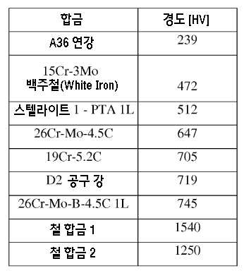
본원에서 사용되는 층별 공법에서, 바람직하게는, 에너지 원, 전형적으로 레이저 또는 전자 빔을 재료 표면 상에 주사하여 에너지 원에 의해 조사된 영역에 국부적인 재료의 층의 적어도 부분적 용해를 유발한다. 원하는 경우, 에너지 원은 또한 특정 깊이의 기저 재료를 용해시키도록 조정될 수 있다. 예를 들어, 에너지 원은 250 마이크로미터 이하의 범위의 깊이에서 용해되도록 조정될 수 있다. 용융 된 재료는 기저 재료와 야금 결합하고 에너지 원이 멀어짐에 따라 응고된다. 추가적 재료가 응고된 재료에 첨가된 다음에 에너지 원으로 조사되어 용해 및 응고를 유발한다. 이 과정이 반복됨에 따라 구축되는 부품의 두께가 증가된다. 상기로부터 알 수 있는 바와 같이, 합금 1 및 합금 2의 예에 관해서, 형성되는 응고 층 또는 복수개의 응고 층의 경도는 보다 구체적으로 약 1200 HV 내지 1600 HV의 범위에 해당할 수 있다. In the layered process used herein, an energy source, typically a laser or electron beam, is scanned onto the material surface to cause at least partial melting of the layer of material local to the area irradiated by the energy source. If desired, the energy source may also be adjusted to dissolve a certain depth of the base material. For example, the energy source can be adjusted to dissolve at a depth in the range of 250 micrometers or less. The molten material is metallurgically bonded to the base material and solidified as the energy source moves away. Additional material is added to the coagulated material and then irradiated with an energy source to cause dissolution and solidification. As this process is repeated, the thickness of the part being built increases. As can be seen from the above, with respect to Examples of
비교적 높은 경도의 재료는 전형적으로 비교적 낮은 연성 및 비교적 낮은 인성을 갖고 그로 인해 이들 재료를 열적 유도 응력에 의한 균열에 취약하게 만들고 액체 상 층별 공법을 통해 가공하기가 역사상 어렵게 만든다. 따라서 열적 유도 응력을 완화하고 높은 경도의 재료의 무균열 층별 공법을 가능하게 하기 위해서는 응력 감소의 방법을 사용하여야 한다. Materials with relatively high hardness typically have relatively low ductility and relatively low toughness, thereby making these materials vulnerable to cracking due to thermal inductive stress and making them difficult to machine through liquid phase layered processes. Therefore, in order to relax the thermal inductive stress and to enable the non-cracked layered method of the material with high hardness, the stress reduction method should be used.
에너지 원이 재료의 층을 용해시킬 때마다 열은 하부에 제작된 부품을 통해 전도되어 재료의 고유 열 팽창 특성으로 인해 기저 재료의 가열시 팽창을 그리고 냉각시 수축을 초래한다. 게다가, 새로운 층의 조사 동안에 생성된 용융 층은 기저 층과 야금 결합을 형성한 다음에 냉각시 수축을 겪는다. 새로운 층과 기저 층 사이의 결합은 계면에서의 합금의 수축을 제한하고 그로 인해 새로운 층에서 압축 응력을 유도한다. 따라서 재료는 층별 공법에서 순환(cyclic) 에너지 원에 의해 유발되는 열 사이클(thermal cycling) 동안에 유도되는 응력으로 인한 균열에 견딜 수 있어야 한다. Whenever an energy source dissolves a layer of material, the heat is conducted through the underlying components, resulting in expansion upon heating of the base material due to inherent thermal expansion characteristics of the material and shrinkage upon cooling. In addition, the molten layer produced during the irradiation of the new layer undergoes shrinkage upon cooling after forming a metallurgical bond with the underlying layer. The bond between the new layer and the base layer limits the shrinkage of the alloy at the interface and thereby induces compressive stress in the new layer. Therefore, the material must be able to withstand cracking due to the stress induced during the thermal cycling induced by the cyclic energy source in the layered process.
이들 응력은, 철 합금의 경우 전형적으로 900℃ 내지 2000℃의 범위인, 용융 재료의 온도와, 철 합금의 경우 전형적으로 25-1400℃의 범위인, 기저 재료의 온도와의 차이를 감소시킴으로써 감소된다. 용융 재료의 온도와 기저 재료의 온도와의 차이는 1950℃ 만큼 클 수 있다. 차이가 작으면 작을수록 응력이 낮고, 최저 응력의 경우는 차이가 없고, 응력이 생성되지 않는다. 따라서, 기저 재료의 가열은 열 응력의 감소에 큰 영향을 미친다. 기저 재료를 40-1000℃의 범위, 보다 바람직하게는 400-1000℃의 범위, 가장 바람직하게는 800-1000℃의 범위의 온도로 가열하는 것이 바람직하다. These stresses are reduced by decreasing the difference between the temperature of the molten material, typically in the range of 900 ° C to 2000 ° C for iron alloys and the temperature of the base material, which is typically in the range of 25-1400 ° C for ferrous alloys do. The difference between the temperature of the molten material and the temperature of the base material may be as large as 1950 ° C. The smaller the difference is, the lower the stress is, and in the case of the lowest stress there is no difference and no stress is generated. Thus, the heating of the base material has a great influence on the reduction of the thermal stress. It is preferred to heat the base material to a temperature in the range of 40-1000 占 폚, more preferably in the range of 400-1000 占 폚, and most preferably in the range of 800-1000 占 폚.
층별 공법은 항상 그의 부품이 제작되어 있는 기판으로 시작한다. 부품 구축이 완료되면 EDM 및 기계적 톱질을 포함한 여러 가지의 기술을 통해 기판으로부터 부품을 제거할 수 있다. 부품을 구축하는데 있어서, 기판에 적용되는 재료의 제1 층은 부품이 제작되는 계면으로서 역할을 하기 때문에 중요한 층이다. 에너지 원이 조사되고 적어도 부분적으로 제1 층을 용해시키는 경우, 이는 기판과 야금 결합을 형성하고 냉각시 제1 층은 수축한다. 기판 및 제1 층이 상이한 열 팽창 특성을 갖는 상이한 재료로 구성되는 경우, 열 팽창 특성에서 상당한 불일치가 존재한다. 일치하지 않는 열 팽창은 각각의 재료가 그 자체 속도로 팽창 및 수축하기를 원할 것이기 때문에, 계면에서 응력을 부여할 것이지만, 이들은 다른 재료에 의해 제한된다. 이로 인해 높은 경도의 재료에 균열을 야기할 수 있는 응력이 발생한다. 기판 재료와 제1 층 재료의 열 팽창 특성 사이의 차이의 감소는 일치하지 않는 열 팽창에 의해 유도되는 응력을 크게 감소시킨다.The layered construction method always starts with the substrate on which its parts are made. Once the part is built, a variety of techniques can be used to remove the part from the substrate, including EDM and mechanical sawing. In constructing the component, the first layer of material applied to the substrate is an important layer because it serves as the interface at which the component is fabricated. When the energy source is irradiated and at least partially dissolves the first layer, it forms a metallurgical bond with the substrate and the first layer shrinks upon cooling. When the substrate and the first layer are constructed of different materials with different thermal expansion properties, there is a significant disparity in the thermal expansion properties. Unmatched thermal expansion will give stress at the interface, since each material will want to expand and contract at its own speed, but these are limited by other materials. This results in stress that can cause cracks in the high hardness material. The reduction in the difference between the thermal expansion characteristics of the substrate material and the first layer material greatly reduces the stress induced by inconsistent thermal expansion.
제1 층에 대한 열 팽창 특성의 상기 언급된 일치와 기판의 이용을 조합하고, 기판 및 제작된 층을 가열함으로써, 열적 유도 응력이 크게 감소되어 다른 방법으로는 유도 응력에 의해 균열에 취약한 일부 재료의 층별 공법을 가능하게 할 수 있다. 도 3은 2 μm/mm·℃의 기판과 제1 층 사이의 열 팽창 계수에서의 불일치 및 200℃의 기판 온도로 층별 구축된 경도 1250 HV의, 높은 경도의 철 재료의 단면을 나타낸다. 합금 조성은 상기 언급된 바와 같은 합금 2이었다. 본원에서 이해되는 바와 같이, 2 μm/m·℃ 이상으로 열 팽창 계수의 불일치가 바람직하게는 회피된다. 따라서, 층상 구조(layered construction) 중의 적용된 합금과 기판의 열 팽창 계수에서의 차이는 바람직하게는 2 μm/m·℃ 미만이다. By combining the above mentioned conformations of the thermal expansion characteristics for the first layer with the use of the substrate and by heating the substrate and the fabricated layer, the thermal induced stress is greatly reduced and some other materials, which are susceptible to cracking by inductive stress It is possible to make a layer-by-layer method. 3 shows a cross-section of a high hardness steel material with a hardness of 1250 HV layered with a substrate temperature of 200 占 폚 and a mismatch in the coefficient of thermal expansion between the substrate of 2 占 퐉 / mm 占 폚 and the first layer. The alloy composition was Alloy 2 as mentioned above. As understood herein, mismatch of the thermal expansion coefficient is preferably avoided at 2 [mu] m / m [deg.] C or more. Thus, the difference in thermal expansion coefficient between the applied alloy and the substrate in the layered construction is preferably less than 2 占 퐉 / m 占 폚.
도 4는 동일한 합금으로부터 구축된, 800℃ 가열 기판 상에 층별 구축된 동일한 합금의 단면을 나타내고, 기판 및 제1 층 둘 다 10.4 μm/m·℃의 열 팽창 계수를 갖고, 그로 인해 어떤 불일치도 존재하지 않도록 한다. 기판 가열을 이용하고 기판과 제1 층 사이의 열 팽창 계수 불일치를 2 μm/m·℃ 이하, 보다 바람직하게는 1 μm/·℃ 이하, 가장 바람직하게는 0.5 μm/m·℃ 이하로 제어하여, 무균열 부품을 생산할 수 있으며, 여기서 어떤 균열도 50X 배율의 현미경 검사에서 식별가능하지 않다. 도 5는 1060 HV의 경도 및 99.9%의 밀도를 갖는 합금 2로부터 이 기술로 생산된 무균열 기능성 베어링 부품을 나타내고, 여기서 0.1%의 부피는 기공으로 이루어지며 나머지는 무균열 고체 재료이다. Figure 4 shows a cross-section of the same alloy layered on a 800 ° C heated substrate constructed from the same alloy and having a coefficient of thermal expansion of both 10.4 μm / m ° C. for both the substrate and the first layer, Do not exist. Substrate heating is used and the thermal expansion coefficient mismatch between the substrate and the first layer is controlled to be 2 탆 / m 占 폚 or lower, more preferably 1 占 퐉 / 占 폚 or lower, and most preferably 0.5 占 퐉 / m 占 폚 or lower , Crack-free parts, where no cracks are identifiable by microscopic examination at 50X magnification. Fig. 5 shows a non-cracking functional bearing component produced with this technique from Alloy 2 having a hardness of 1060 HV and a density of 99.9%, wherein the volume of 0.1% consists of pores and the remainder is a non-cracking solid material.
따라서, 본원에서의 층상 구조는 금속 부품을 제공하는 것이며 여기서 어떤 균열, 기공 또는 다른 유형의 공극도 50x의 배율을 사용한 현미경 검사에서 식별가능하지 않다는 점을 인식하여야 한다. 게다가 금속 부품은 고체 영역(solid domain)이 존재하도록 하고 여기서 존재하는 하나 이상의 층은 95% 이상의 고체인 금속 부품을 규정한다. 이것은 부품의 부피의 95% 이상이 잔여 균열, 기공 또는 다른 유형의 개방 공간 (본원에서는 집합적으로 공극으로서 특정됨)을 갖는 금속 영역의 존재를 특징으로 한다는 특징을 지칭한다. 보다 바람직하게는, 하나 이상의 층은 97% 이상의 고체, 및 훨씬 보다 바람직하게는, 99% 내지 100% 고체인 금속 부품을 규정한다. 따라서, 하나 이상의 층은 이제, 비교적 작은 백분율 (5% 미만)의 공극을 가진, 자립형 부품으로서 95 부피% 이상의 고체 금속 재료인 층상 구조를 제공한다. Thus, it should be appreciated that the layered structure herein provides metal parts, wherein no cracks, pores or other types of pores are identifiable in a microscopic examination using a magnification of 50x. In addition, the metal part allows a solid domain to exist and at least one layer present therein defines a metal part that is at least 95% solid. This refers to the feature that at least 95% of the volume of the component is characterized by the presence of a residual crack, pore or other type of open area (designated collectively as voids herein). More preferably, the at least one layer defines a metallic component that is at least 97% solids, and even more preferably, 99% to 100% solids. Thus, the at least one layer now provides a layered structure that is at least 95% by volume of a solid metal material as a self-contained part, having a relatively small percentage (less than 5%) of voids.
도 6은 유도 응력에 의해 균열에 취약한 층별 구축된 높은 경도의 철 금속의 무균열 단면을 나타낸다. 도 6에서의 합금 조성은 상기에 언급된 합금 1이었다. 개별 층은 70 마이크로미터의 두께를 갖고 전체 두께는 대략 10 mm이었다. 재료는 10.3 μm/m·℃의 열 팽창 계수로, UNS S42000으로부터 구축된, 500℃ 가열 기판을 이용함으로써 균열 없이 구축되었고, 이는 단지 기판과 제1 층 사이에 0.3 μm/m·℃ 불일치를 갖는다. Fig. 6 shows a non-cracked section of a high hardness ferrous metal constructed by layers that is vulnerable to cracking by inductive stress. The alloy composition in Fig. 6 was the above-mentioned
높은 경도가 반드시 높은 내마모성을 초래하는 것은 아니지만, 대부분의 경우 그렇고 그와 같이 층별 공법을 통해 철 합금에서 생성된 높은 경도는 탁월한 내마모성을 초래한다는 점이 고려된다. 표 2에 나타낸 철 합금 2에 대한 ASTM G65-10 절차 A 마모 시험은 24.0 mm3의 부피 손실을 측정한다. 사정이 그렇다면, 바람직하게는, 본원에서의 층별 공법은 바람직하게는 +/-5.0 mm3에서 24.0 mm3의 내마모성을 갖는다.High hardness does not necessarily result in high abrasion resistance, but in most cases it is considered that the high hardness produced in the iron alloy through such a layered process results in excellent abrasion resistance. The ASTM G65-10 Procedure A wear test for iron alloy 2 shown in Table 2 measures the volume loss of 24.0 mm 3 . If so, the assessment, preferably the floor of the method herein has preferably +/- wear resistance at 5.0 mm 3 24.0 mm 3.
본 개시의 바람직한 실시양태가 설명되었지만, 본 개시의 사상 및 첨부된 청구범위의 범주를 벗어나지 않으면서 다양한 변경, 개조 및 수정이 이루어질 수 있음을 이해하여야 한다. 따라서, 본 개시의 범주는 상기 설명을 참조로 결정되어야 하는 것이 아니라, 대신에 등가물의 그의 전체 범주와 함께 첨부된 청구범위를 참조하여 결정되어야 한다. While the preferred embodiments of the present disclosure have been described, it should be understood that various changes, adaptations, and modifications may be made without departing from the spirit of the disclosure and the scope of the appended claims. Accordingly, the scope of this disclosure should not be determined with reference to the above description, but instead should be determined with reference to the appended claims along with their full scope of equivalents.
Claims (15)
기판을 공급하고;
상기 합금을 용융 상태로 용해시켜 상기 합금의 하나 이상의 층을 상기 기판 상으로 적용하고 냉각하고 응고된 층을 형성시키고 여기서 상기 고체 층의 각각이 5.0 내지 200.0 마이크로미터로 형성된 바와 같은 두께를 갖고;
임의로 상기 기판을 제거하여 자립형 금속 부품을 형성시키고 여기서 상기 하나 이상의 고체 층은 900-1800 HV의 범위의 경도를 나타내는 것
을 포함하는, 금속 부품의 적층 방식 공법의 방법.54.0 wt. % To 78.0 wt. % Fe, 3.0 wt. % To 5.0 wt% of B, 14.0 wt. % To 20.0 wt. % Of Cr, 0.5 wt. % To 7.0 wt. % C, optionally 11.0 wt. % Mo, optionally 2.5 wt. % Mn, optionally 4.5 wt. % Nb, optionally 2.0 wt. % Si, optionally 7.0 wt. % ≪ / RTI > of W;
Supplying a substrate;
Dissolving the alloy in a molten state to apply at least one layer of the alloy onto the substrate, cooling and forming a solidified layer, wherein each of the solid layers has a thickness as formed from 5.0 to 200.0 micrometers;
Optionally removing the substrate to form a free-standing metal part, wherein the at least one solid layer exhibits a hardness in the range of 900-1800 HV
Wherein the metal part is formed of a metal.
Applications Claiming Priority (3)
| Application Number | Priority Date | Filing Date | Title |
|---|---|---|---|
| US201461994758P | 2014-05-16 | 2014-05-16 | |
| US61/994,758 | 2014-05-16 | ||
| PCT/US2015/031398 WO2015176061A1 (en) | 2014-05-16 | 2015-05-18 | Layered construction of metallic materials |
Publications (2)
| Publication Number | Publication Date |
|---|---|
| KR20170009902A true KR20170009902A (en) | 2017-01-25 |
| KR102467398B1 KR102467398B1 (en) | 2022-11-14 |
Family
ID=54480853
Family Applications (1)
| Application Number | Title | Priority Date | Filing Date |
|---|---|---|---|
| KR1020167034840A Active KR102467398B1 (en) | 2014-05-16 | 2015-05-18 | Layered construction of metallic materials |
Country Status (11)
| Country | Link |
|---|---|
| US (1) | US10654100B2 (en) |
| EP (1) | EP3142855A4 (en) |
| JP (1) | JP6623177B2 (en) |
| KR (1) | KR102467398B1 (en) |
| CN (1) | CN106457769B (en) |
| AU (1) | AU2015258806B2 (en) |
| CA (1) | CA2949389C (en) |
| IL (1) | IL249008A0 (en) |
| MX (1) | MX2016015028A (en) |
| SG (1) | SG11201609612YA (en) |
| WO (1) | WO2015176061A1 (en) |
Families Citing this family (18)
| Publication number | Priority date | Publication date | Assignee | Title |
|---|---|---|---|---|
| MY190226A (en) * | 2014-07-24 | 2022-04-06 | Oerlikon Metco Us Inc | Hardfacing alloys resistant to hot tearing and cracking |
| AU2016349913B2 (en) * | 2015-11-02 | 2022-07-14 | The Nanosteel Company, Inc. | Layered construction of in-situ metal matrix composites |
| US11248692B2 (en) * | 2016-03-11 | 2022-02-15 | Deere & Company | Composite gears and methods of manufacturing such gears |
| JP6220459B1 (en) * | 2016-03-25 | 2017-10-25 | 技術研究組合次世代3D積層造形技術総合開発機構 | Control method for three-dimensional additive manufacturing apparatus, control method for three-dimensional additive manufacturing apparatus, and control program for three-dimensional additive manufacturing apparatus |
| CA3032821A1 (en) | 2016-08-03 | 2018-02-08 | 3Deo, Inc. | Devices and methods for three-dimensional printing |
| US9987682B2 (en) | 2016-08-03 | 2018-06-05 | 3Deo, Inc. | Devices and methods for three-dimensional printing |
| US10953465B2 (en) | 2016-11-01 | 2021-03-23 | The Nanosteel Company, Inc. | 3D printable hard ferrous metallic alloys for powder bed fusion |
| US10920295B2 (en) * | 2016-11-01 | 2021-02-16 | The Nanosteel Company, Inc. | 3D printable hard ferrous metallic alloys for powder bed fusion |
| DE102016222555A1 (en) * | 2016-11-16 | 2018-05-17 | Siemens Aktiengesellschaft | Method for additive production of a component and computer-readable medium |
| CA3095046A1 (en) | 2018-03-29 | 2019-10-03 | Oerlikon Metco (Us) Inc. | Reduced carbides ferrous alloys |
| JP7641218B2 (en) | 2018-10-26 | 2025-03-06 | エリコン メテコ(ユーエス)インコーポレイテッド | Corrosion and wear resistant nickel-based alloy |
| CN113631750A (en) | 2019-03-28 | 2021-11-09 | 欧瑞康美科(美国)公司 | Thermally sprayed iron-based alloys for coating engine cylinder bores |
| WO2020219345A1 (en) * | 2019-04-24 | 2020-10-29 | Formetrix, Inc. | 3d printable hard ferrous metallic alloys for powder bed fusion |
| EP3962693A1 (en) | 2019-05-03 | 2022-03-09 | Oerlikon Metco (US) Inc. | Powder feedstock for wear resistant bulk welding configured to optimize manufacturability |
| CN110103530B (en) * | 2019-06-04 | 2023-03-31 | 河北工业大学 | High-performance corrosion-resistant TWIP/stainless steel multilayer composite material and preparation method thereof |
| EP3997252B1 (en) | 2019-07-09 | 2025-10-29 | Oerlikon Metco (US) Inc. | Iron-based alloys designed for wear and corrosion resistance |
| CN115605306B (en) * | 2020-04-14 | 2025-08-08 | 麦克林科格集团公司 | Additively manufactured printable hard ferrous metal alloys via direct energy deposition |
| US12226823B2 (en) * | 2020-12-22 | 2025-02-18 | Wisconsin Alumni Research Foundation | Alloy composition, method and apparatus therefor |
Citations (2)
| Publication number | Priority date | Publication date | Assignee | Title |
|---|---|---|---|---|
| WO2002044437A2 (en) * | 2000-11-02 | 2002-06-06 | Composite Tool Company, Inc. | High strength alloys and methods for making same |
| US20070281176A1 (en) * | 2004-12-17 | 2007-12-06 | Integtan Technologies, Inc. | Fine-grained metallic coatings having the coefficient of thermal expansion matched to the one of the substrate |
Family Cites Families (19)
| Publication number | Priority date | Publication date | Assignee | Title |
|---|---|---|---|---|
| US6767419B1 (en) * | 2000-11-09 | 2004-07-27 | Bechtel Bwxt Idaho, Llc | Methods of forming hardened surfaces |
| US6689234B2 (en) * | 2000-11-09 | 2004-02-10 | Bechtel Bwxt Idaho, Llc | Method of producing metallic materials |
| US7341765B2 (en) * | 2004-01-27 | 2008-03-11 | Battelle Energy Alliance, Llc | Metallic coatings on silicon substrates, and methods of forming metallic coatings on silicon substrates |
| DE502005009857D1 (en) * | 2004-01-28 | 2010-08-19 | Ford Global Tech Llc | THROUGH THERMAL SPRAYING OF IRONED LAYER OF A SLIDING SURFACE, IN PARTICULAR FOR CYLINDERS OF ENGINE BLOCKS |
| CN103320783B (en) * | 2004-03-25 | 2016-01-20 | 东北泰克诺亚奇股份有限公司 | Metallic glass laminate, its manufacture method and application thereof |
| CN1997765B (en) * | 2004-05-06 | 2012-05-30 | 巴特尔能源联合有限责任公司 | Method for forming a hardened surface on a substrate |
| US20080141938A1 (en) * | 2006-12-13 | 2008-06-19 | General Electric Company | Processing apparatus, coated article and method |
| US7939142B2 (en) * | 2007-02-06 | 2011-05-10 | Ut-Battelle, Llc | In-situ composite formation of damage tolerant coatings utilizing laser |
| EP1992709B1 (en) * | 2007-05-14 | 2021-09-15 | EOS GmbH Electro Optical Systems | Metal powder for use in additive manufacturing method for the production of three-dimensional objects and method using such metal powder |
| CN101358344B (en) * | 2008-09-01 | 2010-06-02 | 南京钢铁股份有限公司 | Repair method of backup roll surface of steckel mill and special repair powder used thereon |
| SE533076C2 (en) * | 2008-09-05 | 2010-06-22 | Methods for making articles containing nanometal or composite metal | |
| GB0819935D0 (en) * | 2008-10-30 | 2008-12-10 | Mtt Technologies Ltd | Additive manufacturing apparatus and method |
| US8545994B2 (en) | 2009-06-02 | 2013-10-01 | Integran Technologies Inc. | Electrodeposited metallic materials comprising cobalt |
| CA2770485C (en) * | 2009-08-10 | 2018-10-30 | The Nanosteel Company, Inc. | Feedstock powder for production of high hardness overlays |
| CA2779308C (en) * | 2009-10-30 | 2019-01-29 | The Nanosteel Company, Inc. | Glass forming hardbanding material |
| WO2012122120A1 (en) | 2011-03-04 | 2012-09-13 | The Nanosteel Company, Inc | Puncture resistant tire |
| US9316341B2 (en) * | 2012-02-29 | 2016-04-19 | Chevron U.S.A. Inc. | Coating compositions, applications thereof, and methods of forming |
| US20130309121A1 (en) * | 2012-05-16 | 2013-11-21 | Crucible Intellectual Property Llc | Layer-by-layer construction with bulk metallic glasses |
| CN102848102B (en) * | 2012-06-28 | 2015-04-08 | 北京工业大学 | Iron-based abrasion-resistant alloy containing superfine hard phase |
-
2015
- 2015-05-18 WO PCT/US2015/031398 patent/WO2015176061A1/en not_active Ceased
- 2015-05-18 JP JP2016568008A patent/JP6623177B2/en not_active Expired - Fee Related
- 2015-05-18 CA CA2949389A patent/CA2949389C/en active Active
- 2015-05-18 EP EP15792187.5A patent/EP3142855A4/en not_active Withdrawn
- 2015-05-18 MX MX2016015028A patent/MX2016015028A/en unknown
- 2015-05-18 AU AU2015258806A patent/AU2015258806B2/en not_active Ceased
- 2015-05-18 CN CN201580033118.7A patent/CN106457769B/en active Active
- 2015-05-18 SG SG11201609612YA patent/SG11201609612YA/en unknown
- 2015-05-18 KR KR1020167034840A patent/KR102467398B1/en active Active
- 2015-05-18 US US14/715,164 patent/US10654100B2/en not_active Expired - Fee Related
-
2016
- 2016-11-16 IL IL249008A patent/IL249008A0/en unknown
Patent Citations (2)
| Publication number | Priority date | Publication date | Assignee | Title |
|---|---|---|---|---|
| WO2002044437A2 (en) * | 2000-11-02 | 2002-06-06 | Composite Tool Company, Inc. | High strength alloys and methods for making same |
| US20070281176A1 (en) * | 2004-12-17 | 2007-12-06 | Integtan Technologies, Inc. | Fine-grained metallic coatings having the coefficient of thermal expansion matched to the one of the substrate |
Also Published As
| Publication number | Publication date |
|---|---|
| CN106457769B (en) | 2019-09-17 |
| AU2015258806B2 (en) | 2019-05-16 |
| IL249008A0 (en) | 2017-01-31 |
| JP6623177B2 (en) | 2019-12-18 |
| US10654100B2 (en) | 2020-05-19 |
| US20150328680A1 (en) | 2015-11-19 |
| MX2016015028A (en) | 2017-03-27 |
| JP2017530250A (en) | 2017-10-12 |
| WO2015176061A1 (en) | 2015-11-19 |
| SG11201609612YA (en) | 2016-12-29 |
| AU2015258806A1 (en) | 2016-12-08 |
| CN106457769A (en) | 2017-02-22 |
| EP3142855A4 (en) | 2017-12-13 |
| KR102467398B1 (en) | 2022-11-14 |
| CA2949389C (en) | 2023-06-20 |
| EP3142855A1 (en) | 2017-03-22 |
| CA2949389A1 (en) | 2015-11-19 |
Similar Documents
| Publication | Publication Date | Title |
|---|---|---|
| KR102467398B1 (en) | Layered construction of metallic materials | |
| JP7121001B2 (en) | 3D printable hard ferrous metal alloys for powder bed fusion bonding | |
| JP2019523821A (en) | Steel suitable for plastic molds | |
| KR102409141B1 (en) | LAYERED CONSTRUCTION of IN-SITU METAL MATRIX COMPOSITE | |
| WO2018215996A1 (en) | Method and system for improving the surface fracture toughness of brittle materials, and a cutting tool produced by such method | |
| CN107427924A (en) | infiltrated ferrous material | |
| TWI799782B (en) | Cobalt-based alloy structure and manufacturing method thereof | |
| Park et al. | Effect of post‐heat treatment on the tensile and cryogenic impact toughness properties of inconel 718 manufactured by selective laser melting | |
| Thangamani et al. | Enhance the microstructure and mechanical properties of directed energy deposition-Arc (DED-Arc) stainless steel 308L using laser shock peening process | |
| Kannan et al. | Microstructural characterization and mechanical integrity of stainless steel 316L clad layers deposited via wire arc additive manufacturing for nuclear applications | |
| Santhoshsarang et al. | Additive manufacturing of AISI H13 tool steel with combinations of higher laser power and scan speed: Microstructural and mechanical properties insights | |
| Renuga Devi et al. | Brief insights into the role of hot-isostatic pressing treatment for additively manufactured components | |
| CN115916435B (en) | Wear-resistant boride-forming ferroalloys for powder bed fusion additive manufacturing | |
| Azhagarsamy et al. | An overview of metallic materials fabrication by direct energy deposition | |
| Sidhu | Residual stress enhancement of additively manufactured Inconel 718 by laser shock peening and ultrasonic nano-crystal surface modification | |
| Yasi | Evaluation of conventional sintering, induction sintering, and selective laser melting manufacturing procedures of 17-4PH materials | |
| Zhao et al. | Multidimensional Optimization Strategies in Laser-Directed Energy Deposition: Enhancing Material Strength, Toughness, and Process Efficiency | |
| Shah | Influence of micro and mesostructure on the fracture properties of additive manufactured steels |
Legal Events
| Date | Code | Title | Description |
|---|---|---|---|
| PA0105 | International application |
Patent event date: 20161213 Patent event code: PA01051R01D Comment text: International Patent Application |
|
| PG1501 | Laying open of application | ||
| A201 | Request for examination | ||
| PA0201 | Request for examination |
Patent event code: PA02012R01D Patent event date: 20200508 Comment text: Request for Examination of Application |
|
| E902 | Notification of reason for refusal | ||
| PE0902 | Notice of grounds for rejection |
Comment text: Notification of reason for refusal Patent event date: 20210929 Patent event code: PE09021S01D |
|
| E701 | Decision to grant or registration of patent right | ||
| PE0701 | Decision of registration |
Patent event code: PE07011S01D Comment text: Decision to Grant Registration Patent event date: 20220811 |
|
| GRNT | Written decision to grant | ||
| PR0701 | Registration of establishment |
Comment text: Registration of Establishment Patent event date: 20221110 Patent event code: PR07011E01D |
|
| PR1002 | Payment of registration fee |
Payment date: 20221110 End annual number: 3 Start annual number: 1 |
|
| PG1601 | Publication of registration |