KR20170010406A - Open-type compressor - Google Patents
Open-type compressor Download PDFInfo
- Publication number
- KR20170010406A KR20170010406A KR1020167036107A KR20167036107A KR20170010406A KR 20170010406 A KR20170010406 A KR 20170010406A KR 1020167036107 A KR1020167036107 A KR 1020167036107A KR 20167036107 A KR20167036107 A KR 20167036107A KR 20170010406 A KR20170010406 A KR 20170010406A
- Authority
- KR
- South Korea
- Prior art keywords
- oil supply
- supply passage
- axial
- passage
- drive shaft
- Prior art date
- Legal status (The legal status is an assumption and is not a legal conclusion. Google has not performed a legal analysis and makes no representation as to the accuracy of the status listed.)
- Granted
Links
Images


Classifications
-
- F—MECHANICAL ENGINEERING; LIGHTING; HEATING; WEAPONS; BLASTING
- F04—POSITIVE - DISPLACEMENT MACHINES FOR LIQUIDS; PUMPS FOR LIQUIDS OR ELASTIC FLUIDS
- F04B—POSITIVE-DISPLACEMENT MACHINES FOR LIQUIDS; PUMPS
- F04B27/00—Multi-cylinder pumps specially adapted for elastic fluids and characterised by number or arrangement of cylinders
- F04B27/08—Multi-cylinder pumps specially adapted for elastic fluids and characterised by number or arrangement of cylinders having cylinders coaxial with, or parallel or inclined to, main shaft axis
- F04B27/10—Multi-cylinder pumps specially adapted for elastic fluids and characterised by number or arrangement of cylinders having cylinders coaxial with, or parallel or inclined to, main shaft axis having stationary cylinders
- F04B27/1036—Component parts, details, e.g. sealings, lubrication
- F04B27/109—Lubrication
-
- F—MECHANICAL ENGINEERING; LIGHTING; HEATING; WEAPONS; BLASTING
- F04—POSITIVE - DISPLACEMENT MACHINES FOR LIQUIDS; PUMPS FOR LIQUIDS OR ELASTIC FLUIDS
- F04B—POSITIVE-DISPLACEMENT MACHINES FOR LIQUIDS; PUMPS
- F04B39/00—Component parts, details, or accessories, of pumps or pumping systems specially adapted for elastic fluids, not otherwise provided for in, or of interest apart from, groups F04B25/00 - F04B37/00
- F04B39/02—Lubrication
-
- F—MECHANICAL ENGINEERING; LIGHTING; HEATING; WEAPONS; BLASTING
- F04—POSITIVE - DISPLACEMENT MACHINES FOR LIQUIDS; PUMPS FOR LIQUIDS OR ELASTIC FLUIDS
- F04C—ROTARY-PISTON, OR OSCILLATING-PISTON, POSITIVE-DISPLACEMENT MACHINES FOR LIQUIDS; ROTARY-PISTON, OR OSCILLATING-PISTON, POSITIVE-DISPLACEMENT PUMPS
- F04C29/00—Component parts, details or accessories of pumps or pumping installations, not provided for in groups F04C18/00 - F04C28/00
- F04C29/02—Lubrication; Lubricant separation
Landscapes
- Engineering & Computer Science (AREA)
- Mechanical Engineering (AREA)
- General Engineering & Computer Science (AREA)
- Applications Or Details Of Rotary Compressors (AREA)
- Compressor (AREA)
- Rotary Pumps (AREA)
Abstract
특히 고회전수 영역에 있어서의 유로 압력 손실의 증대에 의한 급유량의 저하를 억제하여, 윤활 성능에 대한 신뢰성을 향상시킬 수 있는 개방형 압축기를 제공한다. 일단부가 하우징(2)의 외부로 돌출되어 있는 구동축(9)과, 구동축(9)의 외주부에 마련된 급유 펌프(37)와, 구동축(9) 둘레에 형성되고, 급유 펌프(37)로 퍼 올린 오일이 토출되는 펌프실(39)과, 구동축(9) 내에 그 축선(L) 방향을 따라 천설되며, 펌프실(39)로부터의 오일을 슬라이딩 부위에 급유하는 축방향 급유 통로(41)와, 펌프실(39)의 오일을 축방향 급유 통로(41)로 유도하는 레이디얼 방향 급유 통로(40)를 구비한 개방형 압축기(1)에 있어서, 축방향 급유 통로(41)는, 구동축(9)의 축선(L)에 대하여 소정 치수(Δh) 편심된 위치에 마련되고, 레이디얼 방향 급유 통로(40)는, 축방향 급유 통로(41)의 편심 방향측에 마련되어 있다.Provided is an open type compressor capable of suppressing a decrease in the amount of oil supply due to an increase in flow path pressure loss in a high-speed water region and improving the reliability of lubrication performance. A drive shaft 9 protruded to the outside of the housing 2 at one end thereof, a lubricant pump 37 provided at the outer periphery of the drive shaft 9, An axial oil supply passage 41 which is provided in the drive shaft 9 along the direction of the axis L thereof and which supplies oil from the pump chamber 39 to the sliding portion; And an axial oil supply passage 40 for guiding the oil in the axial oil supply passage 41 to the axial oil supply passage 41. The axial oil supply passage 41 is connected to the axial line of the drive shaft 9 L and the radial oil supply passage 40 is provided on the eccentric direction side of the axial oil supply passage 41. The radial oil supply passage 40 is provided at a position eccentric to the predetermined dimension?
Description
본 발명은, 구동축의 외주에 마련되고, 그 구동축으로 구동되는 급유 펌프에 의하여 퍼 올린 오일을 구동축 내에 축방향을 따라 천설(穿設)되어 있는 급유 통로를 통과시켜 슬라이딩 부위에 급유 가능하게 하고 있는 개방형 압축기에 관한 것이다.According to the present invention, oil pumped by a lubricant pump provided on the outer periphery of a drive shaft is passed through an oil supply passage that is formed along the axial direction in a drive shaft so as to be lubricated at a sliding portion To an open type compressor.
하우징의 내부에 베어링을 통하여 회전 가능하게 지지하고 있는 구동축의 일단부가, 하우징의 외부로 돌출되고, 외부로부터 동력을 얻어 구동되는 가로 배치 타입의 개방형 압축기에 있어서는, 오일통의 윤활유를 급유 펌프에 의하여 퍼 올리며, 그 오일을 베어링 등의 슬라이딩 부위에 급유하여 윤활하는 강제 급유 방식을 채용하는 경우, 특허문헌 1에 나타내는 바와 같이, 구동축의 외주에 그 구동축에 의하여 구동되는 급유 펌프를 마련하고, 그 급유 펌프에 의하여 퍼 올린 오일을 구동축 내에 축방향을 따라 천설되어 있는 급유 통로를 통과시켜 슬라이딩 부위에 급유하는 구성으로 하고 있다.In an open-type compressor of a horizontal arrangement type in which one end portion of a drive shaft rotatably supporting the inside of the housing through a bearing is protruded to the outside of the housing and is driven with power from the outside, In the case of adopting a forced lubrication system in which the lubricant is lubricated and lubricated at a sliding portion of a bearing or the like, as shown in Patent Document 1, a lubricating pump driven by the drive shaft is provided on the outer periphery of the drive shaft, And the oil pumped by the pump is passed through the oil supply passage that is opened in the axial direction along the axial direction of the drive shaft to lubricate the sliding portion.
밀폐형 압축기의 경우, 세로 배치형, 가로 배치형에 한정되지 않으며, 일반적으로 구동축의 축단에 원심식이나 용적식 등의 급유 펌프를 마련하여, 밀폐 용기 내에 충전되어 있는 윤활유를 급유 펌프에 의하여 퍼 올리고, 그 오일을 그대로 구동축 내에 축방향을 따라 천설되어 있는 급유 통로를 통과시켜 슬라이딩 부위에 급유하는 구성을 채용하고 있다. 이와 같은 강제 급유 방식의 것으로서, 구동축의 내부에 축방향을 따라 천설되어 있는 급유 통로를, 그 축선에 대하여 소정 치수 오프셋시켜 마련하고, 원심력을 이용하여 급유 성능을 향상시키도록 한 것이 특허문헌 2에 개시되어 있다.In the case of a hermetically sealed compressor, it is not limited to a vertical arrangement type and a horizontal arrangement type. In general, a lubricating oil pump such as a centrifugal type or a volumetric type is provided at the shaft end of a drive shaft, , And the oil is directly supplied to the sliding portion through an oil supply passage that is opened in the axial direction along the axial direction of the drive shaft. In such a forced lubrication system as described above, the lubrication passage, which is provided along the axial direction in the drive shaft, is offset by a predetermined dimension with respect to the axial line, and the lubrication performance is improved by using the centrifugal force. Lt; / RTI >
상기와 같이, 강제 급유 방식을 채용한 압축기에 있어서, 밀폐형의 경우, 외부 동력을 얻을 필요가 없고, 구동축의 일단을 개방단으로 하여, 축방향으로 급유 통로를 천설할 수 있는 점에서, 원심력에 의한 영향을 받기 어렵게 하여, 구동축의 회전수에 비례하여 급유 펌프의 회전수나 원심력을 증가시킬 수 있다. 이로써, 급유량을 증가시켜, 급유 성능을 향상시킬 수 있기 때문에, 특별히 문제는 없다. 그러나, 개방형 압축기의 경우, 외부 동력을 얻을 필요가 있고, 구동축의 일단을 개방단으로 하는 것이 어렵다. 이로 인하여, 급유 펌프에 의하여 퍼 올린 오일을 일단 구동축 둘레에 형성되어 있는 펌프실에 토출하고, 그 펌프실로부터 구동축에 레이디얼 방향으로 마련된 급유 통로에 의하여 축방향으로 천설되어 있는 급유 통로에 오일을 공급할 필요가 있다.As described above, in the compressor employing the forced lubrication system, in the case of the closed type, there is no need to obtain external power, and one end of the drive shaft can be an open end and the lubrication passage can be opened in the axial direction. It is possible to increase the number of revolutions and centrifugal force of the oil feed pump in proportion to the number of revolutions of the drive shaft. Thereby, there is no particular problem because the oil supply amount can be increased and the oil supply performance can be improved. However, in the case of an open type compressor, it is necessary to obtain an external power, and it is difficult to make one end of the drive shaft an open end. Therefore, it is necessary to discharge the oil pumped by the oil supply pump to the pump chamber formed around the drive shaft, and to supply the oil to the oil supply passage that is axially tilted by the oil supply passage provided in the radial direction from the pump chamber .
따라서, 구조적으로 레이디얼 방향으로 천설되어 있는 급유 통로의 입구 부분에 있어서, 원심력에 의한 압력 손실이 발생하는 것은 피할 수 없다. 이 유로 압력 손실은, 구동축의 회전수가 증가함에 따라 증가하는 경향이 있는 점에서, 축방향 급유 통로가 구동축의 축선(편심 없음) 상에 마련되어 있는 경우, 특히 고회전수 영역에 있어서, 도 3에 나타내는 바와 같이, 급유량이 저하되는 특성이 있었다.Therefore, it is inevitable that a pressure loss due to the centrifugal force occurs at the inlet portion of the oil supply passage structurally tilted in the radial direction. In the case where the axial lubrication oil passage is provided on the axis (no eccentricity) of the drive shaft, in particular, in the high-speed water region, as shown in Fig. 3 As shown in FIG.
본 발명은, 이와 같은 사정을 감안하여 이루어진 것으로서, 특히 고회전수 영역에 있어서의 유로 압력 손실의 증대에 의한 급유량의 저하를 억제하여, 윤활 성능에 대한 신뢰성을 향상시킬 수 있는 개방형 압축기를 제공하는 것을 목적으로 한다.SUMMARY OF THE INVENTION The present invention has been made in view of such circumstances, and it is an object of the present invention to provide an open type compressor capable of suppressing a decrease in the amount of oil supply due to an increase in flow path pressure loss in a high- .
본 발명의 제1 양태는, 하우징 내에 회전 가능하게 지지되고, 그 일단부가 상기 하우징의 외부로 돌출되어 있는 구동축과, 상기 구동축의 외주부에 마련되며, 상기 구동축의 회전에 의하여 구동되는 급유 펌프와, 상기 구동축 둘레에 형성되고, 상기 급유 펌프에 의하여 퍼 올린 오일이 토출되는 펌프실과, 상기 구동축 내에 그 축선 방향을 따라 천설되며, 상기 펌프실로부터의 오일을 슬라이딩 부위에 급유하는 축방향 급유 통로와, 상기 구동축에 마련되고, 상기 펌프실의 오일을 상기 축방향 급유 통로로 유도하는 레이디얼 방향 급유 통로를 구비한 개방형 압축기에 있어서, 상기 축방향 급유 통로는, 상기 구동축의 축선에 대하여 소정 치수 편심된 위치에 마련되며, 상기 레이디얼 방향 급유 통로는, 상기 축방향 급유 통로의 편심 방향측에 마련되어 있는 개방형 압축기이다.A first aspect of the present invention is a fuel cell system including a drive shaft rotatably supported in a housing and having an end protruded to the outside of the housing, a refueling pump provided on an outer periphery of the drive shaft and driven by rotation of the drive shaft, An axial oil supply passage formed around the drive shaft and through which the oil pumped up by the oil supply pump is discharged; an axial oil supply passage ducted in the drive shaft along the axial direction thereof to supply oil from the pump chamber to the sliding portion; And a radial oil supply passage provided in the drive shaft for guiding the oil in the pump chamber to the axial oil supply passage, wherein the axial oil supply passage is provided at a position eccentric to the axial line of the drive shaft And the radial oil supply passage is provided on the eccentric direction side of the axial oil supply passage It is an open compressor.
본 발명의 제1 양태에 의하면, 구동축 내에 천설되어 있는 축방향 급유 통로가, 구동축의 축선에 대하여 소정 치수 편심된 위치에 마련됨과 함께, 급유 펌프에 의하여 퍼 올려진 펌프실의 오일을 축방향 급유 통로로 유도하는 레이디얼 방향 급유 통로가, 축방향 급유 통로의 편심 방향으로 마련되어 있기 때문에, 축방향 급유 통로를 편심시키고, 그 편심 방향측에 레이디얼 방향 급유 통로를 마련하고 있는 만큼 레이디얼 방향 급유 통로의 통로 길이를 짧게 하여, 레이디얼 방향 급유 통로의 입구 부분에 있어서 발생하는 원심력에 의한 유로 압력 손실을 저감시킬 수 있다. 즉, 축방향 급유 통로를 편심시키고 있지 않은 것에서는, 레이디얼 방향 급유 통로의 통로 길이는 구동축 반경이 되지만, 레이디얼 방향 급유 통로를 축방향 급유 통로의 편심 방향측에 마련한 경우, 구동축 반경보다 통로 길이를 짧게 할 수 있어, 그만큼 유로 압력 손실을 저감시킬 수 있다. 또, 축방향 급유 통로를 소정 치수 편심시킴으로써, 축방향 급유 통로 내에서 오일에 작용하는 원심 펌프 효과를 이용하여 슬라이딩 부위에 대한 급유 성능을 높일 수 있다. 따라서, 레이디얼 방향 급유 통로에서의 유로 압력 손실의 저감 효과와, 축방향 급유 통로에 의한 급유 성능의 향상 효과의 상승(相乘) 효과에 의하여, 특히 고회전수 영역에서의 급유량의 저하를 억제하여, 윤활 성능에 대한 신뢰성을 높일 수 있다.According to the first aspect of the present invention, the axial oil supply passage provided in the drive shaft is provided at a position eccentric to the axis of the drive shaft by a predetermined dimension, and the oil in the pump chamber pumped up by the oil supply pump is supplied to the axial oil supply passage Since the axial oil supply passage is eccentrically provided and the radial oil supply passage is provided on the eccentric direction side of the axial oil supply passage, It is possible to reduce the passage pressure loss due to the centrifugal force generated at the inlet portion of the radial oil supply passage. That is, in the case where the axial lubrication passage is not eccentrically adjusted, the passage length of the radial lubrication passage becomes the drive shaft radius. However, when the radial lubrication oil passage is provided on the eccentric direction side of the axial lubrication passage, The length can be shortened, and the flow path loss can be reduced accordingly. Further, by making the axial lubrication passage eccentric to a predetermined dimension, the lubrication performance of the sliding portion can be improved by utilizing the centrifugal pump effect acting on the oil in the axial lubrication passage. Therefore, by virtue of the effect of reducing the flow path pressure loss in the radial direction oil supply passage and the effect of improving the oil supply performance by the axial oil supply passage, it is possible to suppress the decrease of the oil supply amount particularly in the high- So that the reliability of the lubrication performance can be enhanced.
본 발명의 제1 양태의 개방형 압축기에 있어서, 상기 레이디얼 방향 급유 통로는, 상기 편심 방향의 축선 상에 있어서 통로 길이가 최단 길이가 되는 위치에 마련되어도 된다.In the open type compressor of the first aspect of the present invention, the radial oil supply passage may be provided at a position where the passage length is the shortest length on the axis in the eccentric direction.
본 발명의 제1 양태에 의하면, 레이디얼 방향 급유 통로를, 편심 방향의 축선 상에 있어서 통로 길이가 최단 길이가 되는 위치에 마련하고 있기 때문에, 레이디얼 방향 급유 통로의 통로 길이를 축방향 급유 통로의 편심 치수에 상당하는 만큼 짧게 하고, 그 길이를 최단 길이로 하여, 레이디얼 방향 급유 통로의 입구 부분에 있어서 발생하는 원심력에 의한 유로 압력 손실을 최소화시킬 수 있다. 이로써, 고회전수 영역에서의 급유량을 향상시켜, 급유 성능을 더 향상시킬 수 있다.According to the first aspect of the present invention, since the radial oil supply passage is provided at the position where the passage length becomes the shortest length on the axis in the eccentric direction, the passage length of the radial oil supply passage is set to the axial oil supply passage It is possible to minimize the loss of the passage pressure due to the centrifugal force generated at the inlet portion of the radial oil supply passage by making the length as shortest as possible. Thereby, the amount of oil supply in the high-rotation-speed water region can be improved and the lubrication performance can be further improved.
본 발명의 제1 양태의 상술한 어느 하나의 개방형 압축기에 있어서, 상기 축방향 급유 통로의 통로 직경은, 상기 레이디얼 방향 급유 통로의 통로 직경보다 큰 직경이 되어도 된다.In any one of the above-described open-type compressors of the first aspect of the present invention, the passage diameter of the axial oil supply passage may be larger than the diameter of the passage of the radial oil supply passage.
본 발명의 제1 양태에 의하면, 축방향 급유 통로의 통로 직경을, 레이디얼 방향 급유 통로의 통로 직경보다 큰 직경으로 하고 있기 때문에, 편심에 의한 원심 펌프 효과를 얻기 쉽고, 또한 통로 내에서의 유로 압력 손실을 저감시킬 수 있다. 이에 더하여, 레이디얼 방향 급유 통로와 축방향 급유 통로의 연결부를 단차나 버(burr) 등이 발생하지 않도록 연통 가공하여, 레이디얼 방향 급유 통로와 축방향 급유 통로의 연결부에서의 유로 압력 손실의 발생을 방지할 수 있고, 고회전수 영역에서의 급유량의 저하를 억제하여 급유 성능을 향상시킬 수 있다.According to the first aspect of the present invention, since the passage diameter of the axial oil supply passage is set to be larger than the passage diameter of the radial oil supply passage, the effect of centrifugal pump by eccentricity can be easily obtained, The pressure loss can be reduced. In addition, the connection between the radial oil supply passage and the axial oil supply passage is communicated so as not to generate steps, burrs, or the like, so that the flow path pressure loss at the connection portion between the radial oil supply passage and the axial oil supply passage And it is possible to suppress the decrease in the amount of oil supply in the high-speed water region and to improve the lubrication performance.
본 발명에 의하면, 축방향 급유 통로를 편심시키고, 그 편심 방향측에 레이디얼 방향 급유 통로를 마련하고 있는 만큼 레이디얼 방향 급유 통로의 통로 길이를 짧게 하여, 레이디얼 방향 급유 통로의 입구 부분에 있어서 발생하는 원심력에 의한 유로 압력 손실을 저감시킬 수 있음과 함께, 축방향 급유 통로를 소정 치수 편심시킴으로써, 축방향 급유 통로 내에서 오일에 작용하는 원심 펌프 효과를 이용하여 슬라이딩 부위에 대한 급유 성능을 향상시킬 수 있기 때문에, 레이디얼 방향 급유 통로에서의 유로 압력 손실의 저감 효과와, 축방향 급유 통로에 의한 급유 성능의 향상 효과의 상승 효과에 의하여, 특히 고회전수 영역에서의 급유량의 저하를 억제하여, 윤활 성능에 대한 신뢰성을 높일 수 있다.According to the present invention, since the axial oil supply passage is eccentrically provided and the radial oil supply passage is provided in the eccentric direction side, the passage length of the radial oil supply passage can be shortened, and at the inlet portion of the radial oil supply passage The oil passage pressure loss due to the generated centrifugal force can be reduced and the axial lubrication passage is eccentric to a predetermined dimension to improve the lubrication performance of the sliding portion by using the centrifugal pump effect acting on the oil in the axial lubrication passage It is possible to suppress the decrease in the amount of oil supply in the high-rotation-speed water region by virtue of the synergetic effect of reducing the oil passage pressure loss in the radial oil supply passage and the effect of improving the oil supply performance by the axial oil supply passage , Reliability of the lubrication performance can be enhanced.
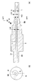
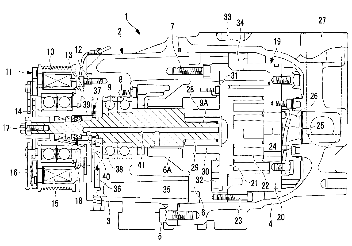
도 1은 본 발명의 실시형태에 관한 개방형 압축기의 종단면도이다.
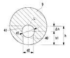
도 2는 상기 개방형 압축기에 있어서의 구동축의 단면도(A)와 그 우측면도(B)이다.
도 3은 도 2(A) 중의 a-a 단면 상당도이다.
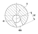
도 4는 상기 구동축에 마련되는 레이디얼 방향 급유 통로의 변형예의 도 3에 상당하는 단면도이다.
도 5는 상기 개방형 압축기에 있어서의 급유 특성을 나타내는 그래프이다.1 is a longitudinal sectional view of an open type compressor according to an embodiment of the present invention.
2 is a cross-sectional view (A) of the drive shaft in the open-type compressor and a right side view (B) thereof.
Fig. 3 is a cross-sectional view taken along line aa in Fig. 2 (A).
Fig. 4 is a sectional view corresponding to Fig. 3 of a modification of the radial oil supply passage provided in the drive shaft.
5 is a graph showing lubrication characteristics in the open type compressor.
이하에, 본 발명에 관한 실시형태에 대하여, 도 1 내지 도 5를 참조하여 설명한다.Hereinafter, embodiments of the present invention will be described with reference to Figs. 1 to 5. Fig.
도 1은, 본 발명의 실시형태에 관한 개방형 압축기의 종단면도를 나타내고, 도 2는, 그 구동축의 단면도(A)와 그 우측면도(B), 도 3 및 도 4는, 각각 도 2(A) 중의 a-a 단면 상당도를 나타내고 있다.2 is a cross-sectional view (A) and a right side view (B) of the drive shaft, and Figs. 3 and 4 are cross-sectional views of the drive shaft shown in Fig. 2 (Aa) section in FIG.
개방형 압축기(1)는, 바닥이 있는 형상을 이루는 프론트 하우징(3)과 리어 하우징(4)을 볼트(5)를 통하여 일체로 결합한 원통 형상의 하우징(2)을 구비하고 있다.The open type compressor 1 is provided with a
하우징(2) 내의 프론트 하우징(3)측의 개구단측에는, 베어링 부재(6)가 볼트(7)를 통하여 고정 설치되고, 이 베어링 부재(6)의 레이디얼 베어링부(6A)와, 프론트 하우징(3) 내에 설치된 구름 베어링(8)에 의하여 구동축(9)을 회전 가능하게 지지하고 있다. 구동축(9)의 일단부는, 프론트 하우징(3)을 관통하여 외부로 돌출되어 있고, 그 돌출 부위에 엔진 등의 외부 구동원으로부터의 동력이 풀리(10) 및 전자(電磁) 클러치(11)를 통하여 입력되도록 되어 있다.A bearing member 6 is fixed to the opening end side of the front housing 3 side of the
풀리(10)는, 프론트 하우징(3)의 전단면(前端面)에 볼트(12)를 통하여 고정 설치된 플랜지 부재(13)의 외주에 구름 베어링(14)을 통하여 회전 가능하게 지지되고, 그 내부에 전자 클러치(11)의 코일 조립(15)을 장착한 것이다. 또, 풀리(10)와 대향하도록, 전자 클러치(11)의 아마추어 조립(16)을, 보스부를 통하여 구동축(9)의 외부 돌출단에 볼트(17)에 의하여 조립되어 있다. 또한, 이 플랜지 부재(13)의 내주에는, 구동축(9)의 관통부를 밀봉 시일하기 위한 메커니컬 시일(18)을 설치하고 있다.The
하우징(2)의 리어 하우징(4)측의 내부에, 압축 기구(19)를 장착하고 있다. 여기에서는, 압축 기구(19)를 한 쌍의 고정 스크롤(20)과, 선회 스크롤(21)을 구비한 스크롤 압축 기구(19)로 하고 있다. 스크롤 압축 기구(19)는, 한 쌍의 고정 스크롤(20) 및 선회 스크롤(21)이 180° 위상(位相)이 어긋나게 맞물리고, 양 스크롤(20, 21) 간에 복수의 압축실(22)을 형성한 것이며, 이와 같은 스크롤 압축 기구(19) 자체는 주지의 것이다.A
고정 스크롤(20)은, 베어링 부재(6)에 볼트(23)를 통하여 체결되어 고정되어 있고, 그 단판(端板) 배면과 리어 하우징(4)의 내면의 사이에 토출 캐비티(26)를 형성하고 있다. 이 고정 스크롤(20)의 단판에, 압축된 가스를 토출 캐비티(26) 내로 토출하는 토출 포트(24)와, 그 토출 포트(24)를 개폐하는 토출 밸브(25)를 마련하고 있다. 또, 리어 하우징(4)에는, 토출 캐비티(26) 내로 토출된 압축 가스를 외부로 토출하는 토출구(27)가 개구되어, 냉동 사이클을 구성하는 토출 배관을 접속 가능하게 하고 있다.The
선회 스크롤(21)은, 단판 배면에 보스부(28)를 가지며, 그 보스부(28)에 대하여, 구동축(9)의 내단측에 마련되어 있는 크랭크 핀(9A)을 드라이브 부시(29) 및 선회 베어링(30)을 통하여 연결시키고, 구동축(9)의 회전에 의하여 크랭크 핀(9A)을 통하여 선회 구동되는 구성으로 하고 있다. 또, 선회 스크롤(21)은, 단판 배면이 베어링 부재(6)에 마련되어 있는 스러스트 베어링(31)으로 지지됨과 함께, 그 단판 배면과 베어링 부재(6)의 사이에 개재된 올담링 또는 핀링 등으로 이루어지는 주지의 자전 저지 기구(32)에 의하여 자전이 저지되어 있고, 고정 스크롤(20)에 대하여 공전 선회 구동하도록 되어 있다.The orbiting
리어 하우징(4)의 전단측의 외주에, 냉동 사이클측의 흡입 배관을 접속하는 흡입구(33)를 마련하고 있고, 그 흡입구(33)로부터 흡입 캐비티(34) 내로 흡입한 저압 가스를 스크롤 압축 기구(19)의 압축실(22)로 흡입시켜 압축하는 구성으로 하고 있다. 본 실시형태에 있어서는, 압축 기구(19)를, 고정 스크롤(20) 및 선회 스크롤(21)의 스파이럴 방향에 있어서, 랩 높이를 변화시키는 단차부를 마련하여, 내주측 랩 높이에 대하여 외주측 랩 높이를 높게 하고, 가스를 원주 방향뿐만 아니라, 축방향으로도 압축할 수 있는 삼차원 압축이 가능한 이른바 단차 스크롤 압축 기구(19)로 하고 있지만, 이에 한정되는 것은 아니다.A
한편, 프론트 하우징(3)의 내부에, 소요량의 윤활유를 충전하고 있고, 프론트 하우징(3) 내의 하부 공간을 오일통(35)으로 함으로써, 그 오일통(35)에 오일을 모으도록 하고 있다. 이 오일통(35)의 오일을, 흡입 통로(36)를 거쳐 급유 펌프(37)에 흡입시키는 구성으로 하고 있다.On the other hand, a required amount of lubricating oil is filled in the front housing 3, and the lower space in the front housing 3 is used as the
급유 펌프(37)는, 프론트 하우징(3)의 전단면을 관통하고 있는 구동축(9)의 외주 부위에 편심부(9B)(도 2 참조)를 형성하고, 그 편심부(9B)에 대하여, 프론트 하우징(3)의 전단면과 플랜지 부재(13)의 단면 간에 형성되는 실린더 내를 편심 회동(回動)하는 로터(38)를 끼워맞춘 구성의 공지의 로터리식 용적형 펌프로 하고 있다.The
급유 펌프(37)에 의하여 오일통(35)으로부터 퍼 올려진 오일은, 구동축(9) 둘레의 편심부(9B)와 메커니컬 시일(18)의 사이에 형성된 펌프실(39) 내로 토출된다. 이 펌프실(39)에 퍼 올려진 오일은, 구동축(9) 내에 마련된 레이디얼 방향 급유 통로(40) 및 축방향 급유 통로(41)를 통과하여 레이디얼 베어링부(6A)나 드라이브 부시(29), 선회 베어링(30), 스러스트 베어링(31) 등의 슬라이딩 부위 혹은 메커니컬 시일(18)의 슬라이딩 부위 등에 공급된다.The oil pumped from the
구동축(9)의 내부에, 그 축선(L)을 따라 마련되는 축방향 급유 통로(41)를, 도 2 및 도 3에 나타내는 바와 같이, 구동축(9)의 축선(L)에 대하여, 소정 치수(편심 치수)(Δh)만큼 편심된 위치에 마련하고 있다. 또, 펌프실(39) 내의 오일을 축방향 급유 통로(41)로 유도하는 레이디얼 방향 급유 통로(40)를, 축방향 급유 통로(41)의 편심 방향으로 마련하고 있다. 본 실시형태에서는, 레이디얼 방향 급유 통로(40)를 편심 방향의 축선 상에서 그 통로 길이(h1)가 최단 길이가 되는 위치에 마련하고 있다. 이로써, 축방향 급유 통로(41)를 구동축(9)의 축선(L) 상에 마련한 것의 통로 길이(h)에 비하여, 레이디얼 방향 급유 통로(40)의 통로 길이(h1)를, Δh(Δh=h-h1)만큼 짧게 할 수 있다.An axial
단, 본 발명은, 상기와 같이, 레이디얼 방향 급유 통로(40)를 편심 방향의 축선 상에 마련하며, 그 통로 길이(h1)를 최단 길이로 한 것에 한정되지 않고, 도 4에 나타내는 바와 같이, 편심 방향의 축선에 대하여 일정 각도를 가진 방향으로 레이디얼 방향 급유 통로(40A)를 마련해도 된다. 이러한 구성에 의해서도, 레이디얼 방향 급유 통로(40A)의 통로 길이(h2)를, 축방향 급유 통로(41)를 구동축(9)의 축선(L) 상에 마련한 것의 통로 길이(h)에 비하여 짧게 할 수 있고, 이 경우의 통로 길이(h2)는, h1<h2<h가 된다. 즉, 펌프실(39)의 오일을 축방향 급유 통로(41)로 유도하는 레이디얼 방향 급유 통로는, 편심 방향의 축선 상에 한정되지 않고, 축방향 급유 통로(41)의 편심 방향측에 마련됨으로써, 그 통로 길이를 구동축(9)의 축선(L) 상에 축방향 급유 통로(41)를 마련한 것에 비하여 짧게 할 수 있다.However, the present invention is not limited to the case where the radial
또, 상기와 같이, 축방향 급유 통로(41) 및 레이디얼 방향 급유 통로(40, 40A)를 마련함에 있어서, 축방향 급유 통로(41)를, 크랭크 핀(9A)의 일단으로부터 축선(L)을 따라 천설된 블라인드 홀로 하고 있다. 한편, 레이디얼 방향 급유 통로(40, 40A)를, 그 블라인드 홀의 선단부 부근에서 레이디얼 방향에 직교하여 마련한 구멍으로 하고 있고, 그 교차부(연결부)에 있어서, 유로 압력 손실의 요인이 되는 단차나 버 등이 발생하지 않도록 할 필요가 있다. 따라서, 축방향 급유 통로(41)의 통로 직경(d1)을, 레이디얼 방향 급유 통로(40, 40A)의 통로 직경(d2)보다 큰 직경(d1>d2)으로 함으로써, 축방향 급유 통로(41)에서 편심에 의한 원심 펌프 효과를 얻기 쉽고, 또한 그 통로 내에서의 유로 압력 손실을 저감시킴과 함께, 양 통로(40, 40A와 41)의 연결부에 있어서 단차나 버 등이 발생하지 않도록 연통 가공할 수 있는 구성으로 하고 있다.When the axial
이상으로 설명한 구성에 의하여, 본 실시형태에 의하면, 이하의 작용 효과를 나타낸다.According to the above-described configuration, the present embodiment exhibits the following operational effects.
상기 개방형 압축기(1)에 있어서, 전자 클러치(11)가 ON이 되면, 풀리(10)를 통하여 외부 구동원으로부터 입력된 동력은, 구동축(9)에 전달되어, 구동축(9)이 회전 구동된다. 이로써, 스크롤 압축 기구(19)의 선회 스크롤(21)이 고정 스크롤(20) 둘레에 공전 선회 구동되어, 흡입구(33)로부터 흡입 캐비티(34) 내에 흡입된 저압 가스를 압축실(22) 내로 흡입시키고, 고압으로 압축하여 토출 포트(24)로부터 토출 캐비티(26) 내로 토출하며, 토출구(27)로부터 냉동 사이클로 토출한다.In the open type compressor 1, when the
이 동안, 구동축(9)의 회전에 의하여 구동되는 급유 펌프(37)는, 흡입 통로(36)를 통하여 오일통(35) 내의 윤활유를 흡입하여, 펌프실(39)로 퍼 올린다. 펌프실(39) 내로 퍼 올려진 오일은, 메커니컬 시일(18)의 슬라이딩 부위를 윤활함과 함께, 레이디얼 방향 급유 통로(40, 40A)를 통하여 축방향 급유 통로(41)로 유도되고, 축방향 급유 통로(41)를 통과하여 레이디얼 베어링부(6A)나 드라이브 부시(29), 선회 베어링(30), 스러스트 베어링(31) 등의 슬라이딩 부위에 대하여 공급되어, 각각의 슬라이딩 부위를 윤활한다. 각 슬라이딩 부위를 윤활한 오일은, 하우징(2)의 바닥부인 오일통(35)에 모아져, 재순환된다.During this time, the
여기에서, 본 실시형태에 있어서는, 축방향 급유 통로(41)를, 구동축(9)의 축선(L)에 대하여 소정 치수(Δh)만큼 편심된 위치에 마련함과 함께, 그 축방향 급유 통로(41)로 펌프실(39) 내의 오일을 유도하는 레이디얼 방향 급유 통로(40, 40A)를, 축방향 급유 통로(41)의 편심 방향측에 마련한다. 이로써, 그 통로 길이(h1, h2)를, 축방향 급유 통로(41)를 구동축(9)의 축선(L) 상에 마련한 것에 비하여 짧게(h1<h2<h) 할 수 있도록 하고 있다.Here, in the present embodiment, the axial
이로 인하여, 축방향 급유 통로(41)를 편심시킨 치수(Δh)분에 상당하게 레이디얼 방향 급유 통로(40, 40A)의 통로 길이(h1, h2)를 짧게 하여, 레이디얼 방향 급유 통로(40, 40A)의 입구 부분에 있어서 발생하는 원심력에 의한 유로 압력 손실을 저감시킬 수 있다. 또, 축방향 급유 통로(41)를 소정 치수(Δh) 편심시킴으로써, 축방향 급유 통로(41) 내에서 오일에 작용하는 원심 펌프 효과를 이용하여 슬라이딩 부위에 대한 급유 성능을 높일 수 있다.Therefore, the passage lengths h1 and h2 of the radial
도 5는, 상기 강제 급유 방식을 채용한 경우의 급유 특성을 가로축에 구동축(9)의 회전수(rpm), 세로축에 급유량(cm3/min)을 취하여 나타낸 그래프이다. 실선으로 나타내는 이론값에 대하여, 축방향 급유 통로(41)를 축선(L) 상에 마련하고 있는 것의 경우, 레이디얼 방향 급유 통로의 통로 길이(h)가 길어지기 때문에, 플롯 □으로 나타내는 바와 같이 고회전수 영역에서 이론값에 대한 급유량이 저하한다. 본 실시형태와 같이, 축방향 급유 통로(41)를 축선(L)에 대하여 편심하여 마련하고, 레이디얼 방향 급유 통로(40, 40A)를 그 편심 방향측에 마련하여 통로 길이(h1, h2)를 짧게 한 것의 경우, 플롯 ▲으로 나타내는 바와 같이 고회전수 영역에서의 급유량을 향상시켜, 이론값에 접근시킬 수 있다.Fig. 5 is a graph showing the fuel supply characteristics in the case of adopting the forced lubrication system by taking the rotation speed (rpm) of the
따라서, 본 실시형태에 의하면, 레이디얼 방향 급유 통로(40, 40A)에서의 유로 압력 손실의 저감 효과와, 축방향 급유 통로(41)에 의한 급유 성능의 향상 효과의 상승 효과에 의하여, 고회전수 영역에서의 급유량의 저하를 억제하여, 윤활 성능에 대한 신뢰성을 높일 수 있다.Therefore, according to the present embodiment, due to the effect of reducing the flow path pressure loss in the radial
특히, 레이디얼 방향 급유 통로(40)를 편심 방향의 축선 상에 있어서, 통로 길이(h1)가 최단 길이가 되는 위치에 마련하고 있다. 이로 인하여, 레이디얼 방향 급유 통로(40)의 통로 길이(h1)를 축방향 급유 통로(41)의 편심 치수(Δh)에 상당하는 만큼 짧게 하고, 그 길이 h1을 최단 길이로 하여, 레이디얼 방향 급유 통로(40)의 입구 부분에 있어서 발생하는 원심력에 의한 유로 압력 손실을 최소화시킬 수 있다. 이로써, 고회전수 영역에서의 급유량을 향상시켜, 급유 성능을 더 향상시킬 수 있다.Particularly, the radial
또, 레이디얼 방향 급유 통로(40, 40A) 및 축방향 급유 통로(41)에 대하여, 축방향 급유 통로(41)의 통로 직경(d1)을 레이디얼 방향 급유 통로(40, 40A)의 통로 직경(d2)보다 큰 직경(d1>d2)으로 하고 있기 때문에, 축방향 급유 통로(41)의 편심에 의한 원심 펌프 효과를 얻기 쉽고, 또한 그 통로 내에서의 유로 압력 손실을 저감시킬 수 있다. 이에 더하여, 레이디얼 방향 급유 통로(40, 40A)와 축방향 급유 통로(41)의 연결부를 단차나 버 등이 발생하지 않도록 연통 가공하여, 양 통로(40, 40A와 41)의 연결부에서의 유로 압력 손실의 발생을 방지할 수 있기 때문에, 그 상승 효과에 의하여, 고회전수 영역에서의 급유량의 저하를 억제하여, 급유 성능을 향상시킬 수 있다.The passage diameter d1 of the axial
특히, 본 실시형태에 관한 개방형 압축기(1)는, 3600rpm 이상의 고속 운전을 하는 강제 급유 방식을 채용한 개방형 스크롤 압축기(1)에 적용한 경우에, 윤활 성능을 향상시킬 수 있다.In particular, when the open-type compressor 1 according to the present embodiment is applied to an open scroll compressor 1 employing a forced lubrication system that performs high-speed operation at 3600 rpm or more, lubrication performance can be improved.
또한, 본 발명은, 상기 실시형태에 관한 발명에 한정되는 것은 아니고, 적절히 변형이 가능하다. 예를 들면, 상기 실시형태에서는, 개방형 압축기(1)의 일례로서, 스크롤식 압축기에 적용한 예에 대하여 설명했지만, 다른 형식의, 예를 들면 로터리식이나 사판(斜板)식, 레시프로식 등의 개방형 압축기에도 동일하게 적용할 수 있는 것은 물론이다.Further, the present invention is not limited to the invention according to the above-described embodiment, but can be suitably modified. For example, in the above-described embodiment, an example in which the present invention is applied to a scroll compressor is described as an example of the open type compressor 1. However, other types of rotary type, swash plate type, It is needless to say that the same can be applied to the open-type compressor of FIG.
또, 급유 펌프(37)에 대해서도, 상기 실시형태에서는, 로터리식의 용적형 펌프를 적용한 예에 대하여 설명했지만, 이에 한정되는 것은 아니고, 나사식의 펌프 등, 다른 형식의 급유 펌프로 해도 된다.In the above-described embodiment, a rotary type displacement pump is applied to the
1 개방형 압축기
2 하우징
9 구동축
37 급유 펌프
39 펌프실
40, 40A 레이디얼 방향 급유 통로
41 축방향 급유 통로
L 구동축의 축선
Δh 편심 치수
h1, h2 레이디얼 방향 급유 통로의 통로 길이
d1 축방향 급유 통로의 통로 직경
d2 레이디얼 방향 급유 통로의 통로 직경1 open type compressor
2 housing
9 drive shaft
37 Lubrication pump
39 pump room
40, 40A Radial lubrication passage
41 axial lubrication passage
L axis of the drive shaft
Δh Eccentric dimension
h1, h2 Passage length of radial lubrication passage
d1 Axial lubrication passage diameter
d2 Passage diameter of radial oil supply passage
Claims (3)
상기 구동축의 외주부에 마련되며, 상기 구동축의 회전에 의하여 구동되는 급유 펌프와,
상기 구동축 둘레에 형성되고, 상기 급유 펌프에 의하여 퍼 올린 오일이 토출되는 펌프실과,
상기 구동축 내에 그 축선 방향을 따라 천설되며, 상기 펌프실로부터의 오일을 슬라이딩 부위에 급유하는 축방향 급유 통로와,
상기 구동축에 마련되고, 상기 펌프실의 오일을 상기 축방향 급유 통로로 유도하는 레이디얼 방향 급유 통로를 구비한 개방형 압축기에 있어서,
상기 축방향 급유 통로는, 상기 구동축의 축선에 대하여 소정 치수 편심된 위치에 마련되며,
상기 레이디얼 방향 급유 통로는, 상기 축방향 급유 통로의 편심 방향측에 마련되어 있는 개방형 압축기.A drive shaft rotatably supported in the housing and having one end protruded to the outside of the housing;
A fuel supply pump provided at an outer periphery of the drive shaft and driven by rotation of the drive shaft,
A pump chamber formed around the drive shaft and through which oil pumped by the oil supply pump is discharged;
An axial oil supply passage that is opened in the axial direction along the axial direction of the drive shaft and supplies oil from the pump chamber to the sliding portion,
And a radial oil supply passage provided in the drive shaft for guiding the oil in the pump chamber to the axial oil supply passage,
Wherein the axial oil supply passage is provided at a position eccentric to the axial line of the drive shaft by a predetermined dimension,
And the radial oil supply passage is provided on the eccentric direction side of the axial oil supply passage.
상기 레이디얼 방향 급유 통로는, 상기 편심 방향의 축선 상에 있어서 통로 길이가 최단 길이가 되는 위치에 마련되어 있는 개방형 압축기.The method according to claim 1,
Wherein the radial oil supply passage is provided at a position where the passage length becomes the shortest length on the axis of the eccentric direction.
상기 축방향 급유 통로의 통로 직경은, 상기 레이디얼 방향 급유 통로의 통로 직경보다 큰 직경으로 되어 있는 개방형 압축기.The method according to claim 1 or 2,
And the passage diameter of the axial oil supply passage is larger than the passage diameter of the radial oil supply passage.
Applications Claiming Priority (3)
| Application Number | Priority Date | Filing Date | Title |
|---|---|---|---|
| JPJP-P-2014-162441 | 2014-08-08 | ||
| JP2014162441A JP6462265B2 (en) | 2014-08-08 | 2014-08-08 | Open type compressor |
| PCT/JP2015/072069 WO2016021590A1 (en) | 2014-08-08 | 2015-08-04 | Open-type compressor |
Related Child Applications (1)
| Application Number | Title | Priority Date | Filing Date |
|---|---|---|---|
| KR1020187028281A Division KR20180112091A (en) | 2014-08-08 | 2015-08-04 | Open-type compressor |
Publications (2)
| Publication Number | Publication Date |
|---|---|
| KR20170010406A true KR20170010406A (en) | 2017-01-31 |
| KR102096139B1 KR102096139B1 (en) | 2020-04-01 |
Family
ID=55263852
Family Applications (2)
| Application Number | Title | Priority Date | Filing Date |
|---|---|---|---|
| KR1020187028281A Withdrawn KR20180112091A (en) | 2014-08-08 | 2015-08-04 | Open-type compressor |
| KR1020167036107A Active KR102096139B1 (en) | 2014-08-08 | 2015-08-04 | Open-type compressor |
Family Applications Before (1)
| Application Number | Title | Priority Date | Filing Date |
|---|---|---|---|
| KR1020187028281A Withdrawn KR20180112091A (en) | 2014-08-08 | 2015-08-04 | Open-type compressor |
Country Status (6)
| Country | Link |
|---|---|
| EP (1) | EP3150855B1 (en) |
| JP (1) | JP6462265B2 (en) |
| KR (2) | KR20180112091A (en) |
| CN (1) | CN106662093A (en) |
| AU (1) | AU2015300143B2 (en) |
| WO (1) | WO2016021590A1 (en) |
Citations (3)
| Publication number | Priority date | Publication date | Assignee | Title |
|---|---|---|---|---|
| KR950011375B1 (en) * | 1981-03-08 | 1995-10-02 | 가부시키가이샤 도시바 | Fluid compressor with two spiral blade |
| JPH08219063A (en) | 1995-02-13 | 1996-08-27 | Daikin Ind Ltd | Lubricating oil supply structure for rotating shaft |
| JP2005282446A (en) | 2004-03-29 | 2005-10-13 | Mitsubishi Heavy Ind Ltd | Scroll compressor |
Family Cites Families (4)
| Publication number | Priority date | Publication date | Assignee | Title |
|---|---|---|---|---|
| JPH05149277A (en) * | 1991-11-26 | 1993-06-15 | Mitsubishi Heavy Ind Ltd | Horizontal type closed scroll compressor |
| CN2688935Y (en) * | 2004-01-21 | 2005-03-30 | 柳州高新区浦发汽车空调有限公司 | Volumetric vortex fluid compressor |
| JP2012097577A (en) * | 2010-10-29 | 2012-05-24 | Daikin Industries Ltd | Compressor |
| CN202520559U (en) * | 2012-03-14 | 2012-11-07 | 广东美芝精密制造有限公司 | Crankshaft structure of rolling rotor compressor |
-
2014
- 2014-08-08 JP JP2014162441A patent/JP6462265B2/en active Active
-
2015
- 2015-08-04 KR KR1020187028281A patent/KR20180112091A/en not_active Withdrawn
- 2015-08-04 KR KR1020167036107A patent/KR102096139B1/en active Active
- 2015-08-04 EP EP15829255.7A patent/EP3150855B1/en active Active
- 2015-08-04 AU AU2015300143A patent/AU2015300143B2/en active Active
- 2015-08-04 WO PCT/JP2015/072069 patent/WO2016021590A1/en not_active Ceased
- 2015-08-04 CN CN201580033419.XA patent/CN106662093A/en active Pending
Patent Citations (3)
| Publication number | Priority date | Publication date | Assignee | Title |
|---|---|---|---|---|
| KR950011375B1 (en) * | 1981-03-08 | 1995-10-02 | 가부시키가이샤 도시바 | Fluid compressor with two spiral blade |
| JPH08219063A (en) | 1995-02-13 | 1996-08-27 | Daikin Ind Ltd | Lubricating oil supply structure for rotating shaft |
| JP2005282446A (en) | 2004-03-29 | 2005-10-13 | Mitsubishi Heavy Ind Ltd | Scroll compressor |
Also Published As
| Publication number | Publication date |
|---|---|
| KR20180112091A (en) | 2018-10-11 |
| JP6462265B2 (en) | 2019-01-30 |
| EP3150855B1 (en) | 2020-04-22 |
| WO2016021590A1 (en) | 2016-02-11 |
| EP3150855A4 (en) | 2017-06-28 |
| EP3150855A1 (en) | 2017-04-05 |
| AU2015300143A1 (en) | 2017-01-19 |
| KR102096139B1 (en) | 2020-04-01 |
| CN106662093A (en) | 2017-05-10 |
| AU2015300143B2 (en) | 2018-05-10 |
| JP2016037922A (en) | 2016-03-22 |
Similar Documents
| Publication | Publication Date | Title |
|---|---|---|
| US10781817B2 (en) | Compressor having centrifugation and differential pressure structure for oil supplying | |
| US9512842B2 (en) | Rotary compressor | |
| WO2015022775A1 (en) | Scroll compressor | |
| EP3214312B1 (en) | Two-cylinder hermetic compressor | |
| US20140023538A1 (en) | Vane rotary compressor | |
| JP5366884B2 (en) | Vane rotary compressor | |
| JP6134903B2 (en) | Positive displacement compressor | |
| JP2012219654A (en) | Rotary fluid machine | |
| CN108350869B (en) | Fluid machinery | |
| KR102310348B1 (en) | Rotary comppresor | |
| JP6906887B2 (en) | Scroll fluid machine | |
| CN106151038B (en) | Screw compressor and air conditioner | |
| KR102096139B1 (en) | Open-type compressor | |
| EP2735742B1 (en) | Fluid machine | |
| JP5999922B2 (en) | Scroll compressor | |
| EP3315781B1 (en) | Open type compressor | |
| KR102608742B1 (en) | Rotary compressor | |
| JP3574904B2 (en) | Closed displacement compressor | |
| KR100299589B1 (en) | Fluid appatus | |
| JP7847347B2 (en) | Scroll compressor | |
| JP2012211569A (en) | Rotary compressor | |
| KR102031851B1 (en) | Motor operated compressor | |
| JP2015105616A (en) | Rotary compressor | |
| JP6756551B2 (en) | Open compressor | |
| WO2020230230A1 (en) | Rotary compressor |
Legal Events
| Date | Code | Title | Description |
|---|---|---|---|
| A201 | Request for examination | ||
| PA0105 | International application |
Patent event date: 20161223 Patent event code: PA01051R01D Comment text: International Patent Application |
|
| PA0201 | Request for examination | ||
| PG1501 | Laying open of application | ||
| E902 | Notification of reason for refusal | ||
| PE0902 | Notice of grounds for rejection |
Comment text: Notification of reason for refusal Patent event date: 20180321 Patent event code: PE09021S01D |
|
| E601 | Decision to refuse application | ||
| PE0601 | Decision on rejection of patent |
Patent event date: 20180830 Comment text: Decision to Refuse Application Patent event code: PE06012S01D Patent event date: 20180321 Comment text: Notification of reason for refusal Patent event code: PE06011S01I |
|
| A107 | Divisional application of patent | ||
| J201 | Request for trial against refusal decision | ||
| PA0104 | Divisional application for international application |
Comment text: Divisional Application for International Patent Patent event code: PA01041R01D Patent event date: 20181001 |
|
| PJ0201 | Trial against decision of rejection |
Patent event date: 20181001 Comment text: Request for Trial against Decision on Refusal Patent event code: PJ02012R01D Patent event date: 20180830 Comment text: Decision to Refuse Application Patent event code: PJ02011S01I Appeal kind category: Appeal against decision to decline refusal Appeal identifier: 2018101004055 Request date: 20181001 |
|
| J301 | Trial decision |
Free format text: TRIAL NUMBER: 2018101004055; TRIAL DECISION FOR APPEAL AGAINST DECISION TO DECLINE REFUSAL REQUESTED 20181001 Effective date: 20200103 |
|
| PJ1301 | Trial decision |
Patent event code: PJ13011S01D Patent event date: 20200103 Comment text: Trial Decision on Objection to Decision on Refusal Appeal kind category: Appeal against decision to decline refusal Request date: 20181001 Decision date: 20200103 Appeal identifier: 2018101004055 |
|
| PS0901 | Examination by remand of revocation | ||
| S901 | Examination by remand of revocation | ||
| GRNO | Decision to grant (after opposition) | ||
| PS0701 | Decision of registration after remand of revocation |
Patent event date: 20200129 Patent event code: PS07012S01D Comment text: Decision to Grant Registration Patent event date: 20200107 Patent event code: PS07011S01I Comment text: Notice of Trial Decision (Remand of Revocation) |
|
| GRNT | Written decision to grant | ||
| PR0701 | Registration of establishment |
Comment text: Registration of Establishment Patent event date: 20200326 Patent event code: PR07011E01D |
|
| PR1002 | Payment of registration fee |
Payment date: 20200326 End annual number: 3 Start annual number: 1 |
|
| PG1601 | Publication of registration | ||
| PR1001 | Payment of annual fee |
Payment date: 20230220 Start annual number: 4 End annual number: 4 |
|
| PR1001 | Payment of annual fee |
Payment date: 20240305 Start annual number: 5 End annual number: 5 |
|
| PR1001 | Payment of annual fee |
Payment date: 20250217 Start annual number: 6 End annual number: 6 |