KR20170010992A - 펄스 전원 장치 - Google Patents
펄스 전원 장치 Download PDFInfo
- Publication number
- KR20170010992A KR20170010992A KR1020150102809A KR20150102809A KR20170010992A KR 20170010992 A KR20170010992 A KR 20170010992A KR 1020150102809 A KR1020150102809 A KR 1020150102809A KR 20150102809 A KR20150102809 A KR 20150102809A KR 20170010992 A KR20170010992 A KR 20170010992A
- Authority
- KR
- South Korea
- Prior art keywords
- unit
- power
- semiconductor switch
- semiconductor
- pulse
- Prior art date
- Legal status (The legal status is an assumption and is not a legal conclusion. Google has not performed a legal analysis and makes no representation as to the accuracy of the status listed.)
- Granted
Links
- 239000004065 semiconductor Substances 0.000 claims abstract description 117
- 238000004146 energy storage Methods 0.000 claims abstract description 20
- 239000003990 capacitor Substances 0.000 claims description 58
- 238000000034 method Methods 0.000 claims description 17
- 238000007599 discharging Methods 0.000 abstract description 6
- 230000007257 malfunction Effects 0.000 abstract description 5
- 238000010586 diagram Methods 0.000 description 12
- 238000004804 winding Methods 0.000 description 10
- 238000009413 insulation Methods 0.000 description 4
- 230000007423 decrease Effects 0.000 description 2
- 238000005516 engineering process Methods 0.000 description 2
- 230000001360 synchronised effect Effects 0.000 description 2
- 230000005856 abnormality Effects 0.000 description 1
- 238000010420 art technique Methods 0.000 description 1
- 230000000694 effects Effects 0.000 description 1
- 238000002955 isolation Methods 0.000 description 1
- 238000004904 shortening Methods 0.000 description 1
- XLYOFNOQVPJJNP-UHFFFAOYSA-N water Substances O XLYOFNOQVPJJNP-UHFFFAOYSA-N 0.000 description 1
- 238000003079 width control Methods 0.000 description 1
Images


Classifications
-
- H—ELECTRICITY
- H02—GENERATION; CONVERSION OR DISTRIBUTION OF ELECTRIC POWER
- H02M—APPARATUS FOR CONVERSION BETWEEN AC AND AC, BETWEEN AC AND DC, OR BETWEEN DC AND DC, AND FOR USE WITH MAINS OR SIMILAR POWER SUPPLY SYSTEMS; CONVERSION OF DC OR AC INPUT POWER INTO SURGE OUTPUT POWER; CONTROL OR REGULATION THEREOF
- H02M3/00—Conversion of DC power input into DC power output
- H02M3/02—Conversion of DC power input into DC power output without intermediate conversion into AC
- H02M3/04—Conversion of DC power input into DC power output without intermediate conversion into AC by static converters
- H02M3/06—Conversion of DC power input into DC power output without intermediate conversion into AC by static converters using resistors or capacitors, e.g. potential divider
- H02M3/07—Conversion of DC power input into DC power output without intermediate conversion into AC by static converters using resistors or capacitors, e.g. potential divider using capacitors charged and discharged alternately by semiconductor devices with control electrode, e.g. charge pumps
-
- H—ELECTRICITY
- H03—ELECTRONIC CIRCUITRY
- H03K—PULSE TECHNIQUE
- H03K3/00—Circuits for generating electric pulses; Monostable, bistable or multistable circuits
- H03K3/02—Generators characterised by the type of circuit or by the means used for producing pulses
- H03K3/53—Generators characterised by the type of circuit or by the means used for producing pulses by the use of an energy-accumulating element discharged through the load by a switching device controlled by an external signal and not incorporating positive feedback
- H03K3/57—Generators characterised by the type of circuit or by the means used for producing pulses by the use of an energy-accumulating element discharged through the load by a switching device controlled by an external signal and not incorporating positive feedback the switching device being a semiconductor device
Landscapes
- Engineering & Computer Science (AREA)
- Power Engineering (AREA)
- Power Conversion In General (AREA)
- Electronic Switches (AREA)
Abstract
Description
도 2a 및 도 2b는 본 발명의 바람직한 실시예에 따른 펄스 전원 장치의 구성을 도시하는 도면이다.
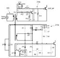
도 3은 본 발명의 바람직한 실시예에 따른 구동부의 세부 구성을 도시하는 회로도이다.
도 4는 본 발명의 바람직한 실시예에 따른 구동부의 턴온 모드 동작을 설명하는 회로도이다.
도 5는 본 발명의 바람직한 실시예에 따른 구동부의 턴온 후 유지 모드 동작을 설명하는 회로도이다.
도 6은 본 발명의 바람직한 실시예에 따른 구동부의 턴 오프 모드 동작을 설명하는 회로도이다.
300 : 콘트롤 인버터
400 : 파워 인버터
500 : 콘트롤 루프
600 : 파워 루프
1000 : 부하 장치
C_ST1 ~ C_ST48 : 충전 커패시터
IGBT1 ~ IGBT48 : 반도체 스위치
IGBT_BP1 ~ IGBT_BP48 : 반도체 스위칭 소자
D_REC1 ~ D_REC48 : 정류 다이오드
Claims (9)
- 반도체 스위치부;
상기 반도체 스위치부가 온되면, 내부에 충전된 전압을 부하 장치로 방전하도록 상기 반도체 스위치부와 직렬로 연결된 에너지 저장부;
상기 에너지 저장부에 전기 에너지를 공급하는 에너지 공급부;
내부에 포함된 역병렬 다이오드의 순방향이 상기 에너지 저장부의 방전 방향과 일치하도록 상기 반도체 스위치부 및 상기 에너지 저장부와 병렬로 연결된 바이패스 스위칭부; 및
상기 반도체 스위치부 및 상기 바이패스 스위칭부를 구동하는 구동부;를 포함하는 파워 셀을 하나 이상 포함하는 것을 특징으로 하는 펄스 전원 장치. - 제 1 항에 있어서,
상기 펄스 전원 장치는 복수의 파워 셀을 포함하고,
상기 복수의 파워 셀에 각각 포함된 상기 반도체 스위치부 및 상기 에너지 저장부가 서로 직렬로 연결되도록 상기 복수의 파워 셀은 서로 직렬로 연결된 것을 특징으로 하는 펄스 전원 장치. - 제 1 항에 있어서,
상기 구동부로 턴 온 펄스 신호와 턴 오프 펄스가 순차적으로 입력되고,
상기 구동부는 턴 온 펄스 신호가 입력되면 상기 반도체 스위치부를 턴 온시켜 상기 에너지 저장부에 충전된 전압을 상기 부하 장치로 방전시키고, 턴 오프 펄스 신호가 입력되면, 상기 반도체 스위치부를 오프시키고 상기 바이패스 스위칭부를 턴 온시켜, 상기 부하 장치 내부에 충전되었던 전압을 상기 바이패스 스위칭부를 통해서 방전시키는 것을 특징으로 하는 펄스 전원 장치. - 제 1 항에 있어서,
상기 에너지 저장부는 서로 직렬로 연결된 한 쌍의 충전 커패시터를 포함하고,
상기 에너지 공급부는 서로 직렬로 연결된 한 쌍의 정류 다이오드를 포함하며,
상기 반도체 스위치부는 각각이 상기 충전 커패시터와 연결되는 한 쌍의 반도체 스위치를 포함하고,
상기 바이패스 스위칭부는 한 쌍의 반도체 스위칭 소자를 포함하며, 각 반도체 스위칭 소자는 서로 직렬로 연결된 상기 충전 커패시터와 상기 반도체 스위치의 양단에 연결되는 것을 특징으로 하는 펄스 전원 장치. - 제 1 항에 있어서,
상기 에너지 저장부는 충전 커패시터를 포함하고, 상기 에너지 공급부는 교류 전원을 입력받아 직류 전원으로 변환하여 상기 충전 커패시터를 충전시키는 정류회로인 것을 특징으로 하는 펄스 전원 장치. - 제 1 항에 있어서, 상기 구동부는
콘트롤 인버터로부터 입력되는 턴 온 펄스 신호에 따라서 상기 반도체 스위치부를 턴 온 시키고, 턴 오프 펄스 신호가 입력될때까지 상기 반도체 스위치부의 턴 온 상태를 유지하는 제 1 구동부; 및
상기 콘트롤 인버터로부터 턴 오프 펄스 신호가 입력되면 상기 바이패스 스위칭부를 턴 온 시키는 제 2 구동부를 포함하는 것을 특징으로 하는 펄스 전원 장치. - 제 6 항에 있어서,
상기 콘트롤 인버터로부터 턴 오프 펄스 신호가 입력되면, 상기 제 2 구동부는 상기 제 1 구동부가 상기 반도체 스위치부를 턴 오프시킨 후, 사전에 정의된 지연 시간이 경과된 후에 상기 바이패스 스위칭부를 턴 온 시키는 것을 특징으로 하는 펄스 전원 장치. - 제 1 항 내지 제 7 항 중 어느 한 항에 있어서,
상기 반도체 스위치부 및 상기 바이패스 스위칭부는 IGBT(Insulated-Gate Bipolar Transistor)로 구현되는 것을 특징으로 하는 펄스 전원 장치. - 제 1 항 내지 제 7 항 중 어느 한 항에 있어서,
상기 에너지 저장부의 충전을 위한 전원을 공급하는 파워 인버터;
상기 파워 인버터로부터 각 파워 셀 내 에너지 공급부에 전원이 공급되도록 하는 파워 루프;
상기 반도체 스위치부 및 상기 반도체 스위칭부에 전원 및 제어신호를 제공하는 컨트롤 인버터; 및
상기 컨트롤 인버터로부터 각 파워 셀 내 구동부에 제어신호가 공급되도록 하는 컨트롤 루프;를 더 포함하는 것을 특징으로 하는 펄스 전원 장치.
Priority Applications (2)
| Application Number | Priority Date | Filing Date | Title |
|---|---|---|---|
| KR1020150102809A KR101739882B1 (ko) | 2015-07-21 | 2015-07-21 | 펄스 전원 장치 |
| PCT/KR2015/012761 WO2017014368A1 (ko) | 2015-07-21 | 2015-11-26 | 펄스 전원 장치 |
Applications Claiming Priority (1)
| Application Number | Priority Date | Filing Date | Title |
|---|---|---|---|
| KR1020150102809A KR101739882B1 (ko) | 2015-07-21 | 2015-07-21 | 펄스 전원 장치 |
Publications (2)
| Publication Number | Publication Date |
|---|---|
| KR20170010992A true KR20170010992A (ko) | 2017-02-02 |
| KR101739882B1 KR101739882B1 (ko) | 2017-05-25 |
Family
ID=57834463
Family Applications (1)
| Application Number | Title | Priority Date | Filing Date |
|---|---|---|---|
| KR1020150102809A Active KR101739882B1 (ko) | 2015-07-21 | 2015-07-21 | 펄스 전원 장치 |
Country Status (2)
| Country | Link |
|---|---|
| KR (1) | KR101739882B1 (ko) |
| WO (1) | WO2017014368A1 (ko) |
Cited By (5)
| Publication number | Priority date | Publication date | Assignee | Title |
|---|---|---|---|---|
| WO2019088354A1 (ko) * | 2017-10-31 | 2019-05-09 | 한국전기연구원 | 절연형 게이트 구동 장치 |
| KR102448125B1 (ko) * | 2021-04-02 | 2022-09-27 | 중앙대학교 산학협력단 | 고전압 펄스 전원 장치 및 이의 동작 방법 |
| KR20220140118A (ko) * | 2021-04-09 | 2022-10-18 | 중앙대학교 산학협력단 | 반도체 스위치를 이용한 펄스 전원 장치 및 이의 고속 게이트 제어 방법 |
| KR20240020413A (ko) * | 2022-08-08 | 2024-02-15 | 중앙대학교 산학협력단 | 펄스 전원 장치 및 반도체 스위치를 제어하는 게이트 드라이버 |
| WO2025105698A1 (ko) * | 2023-11-13 | 2025-05-22 | 한국전기연구원 | 펄스성형장치 및 이를 이용한 펄스성형방법 |
Families Citing this family (5)
| Publication number | Priority date | Publication date | Assignee | Title |
|---|---|---|---|---|
| KR102410532B1 (ko) | 2020-10-30 | 2022-06-16 | 한국전기연구원 | 모듈형 펄스 전원 장치 |
| CN113824431B (zh) * | 2021-08-11 | 2025-08-08 | 杭州维纳安可医疗科技有限责任公司 | 协同脉冲发生电路、发生装置及其发生方法 |
| JP7728439B2 (ja) | 2021-08-11 | 2025-08-22 | 杭州維納安可医療科技有限責任公司 | シナジーパルス発生回路、発生装置及びその発生方法 |
| KR102732989B1 (ko) * | 2023-01-09 | 2024-11-25 | 한국전기연구원 | 스위치스태킹회로 및 이를 포함하는 스위치스태킹장치 |
| KR20260042000A (ko) | 2024-09-20 | 2026-03-30 | 고등기술연구원연구조합 | 수처리용 전원공급장치 |
Family Cites Families (5)
| Publication number | Priority date | Publication date | Assignee | Title |
|---|---|---|---|---|
| JP2001169570A (ja) * | 1999-12-09 | 2001-06-22 | Mitsubishi Electric Corp | パルス電源装置 |
| KR100403383B1 (ko) * | 2001-08-07 | 2003-11-01 | 한국전기연구원 | 반도체 스위치와 고주파 변압기를 조합한 펄스형 및계단파형 고전압 발생장치 |
| JP3623181B2 (ja) * | 2001-08-27 | 2005-02-23 | オリジン電気株式会社 | 高電圧半導体スイッチ装置および高電圧発生装置 |
| KR100567169B1 (ko) * | 2003-05-30 | 2006-04-04 | 한국전기연구원 | 반도체 소자를 이용한 양방향 고압 펄스 전원 장치 |
| KR100820171B1 (ko) | 2006-11-02 | 2008-04-07 | 한국전기연구원 | 반도체 스위치를 이용한 펄스전원장치 |
-
2015
- 2015-07-21 KR KR1020150102809A patent/KR101739882B1/ko active Active
- 2015-11-26 WO PCT/KR2015/012761 patent/WO2017014368A1/ko not_active Ceased
Cited By (5)
| Publication number | Priority date | Publication date | Assignee | Title |
|---|---|---|---|---|
| WO2019088354A1 (ko) * | 2017-10-31 | 2019-05-09 | 한국전기연구원 | 절연형 게이트 구동 장치 |
| KR102448125B1 (ko) * | 2021-04-02 | 2022-09-27 | 중앙대학교 산학협력단 | 고전압 펄스 전원 장치 및 이의 동작 방법 |
| KR20220140118A (ko) * | 2021-04-09 | 2022-10-18 | 중앙대학교 산학협력단 | 반도체 스위치를 이용한 펄스 전원 장치 및 이의 고속 게이트 제어 방법 |
| KR20240020413A (ko) * | 2022-08-08 | 2024-02-15 | 중앙대학교 산학협력단 | 펄스 전원 장치 및 반도체 스위치를 제어하는 게이트 드라이버 |
| WO2025105698A1 (ko) * | 2023-11-13 | 2025-05-22 | 한국전기연구원 | 펄스성형장치 및 이를 이용한 펄스성형방법 |
Also Published As
| Publication number | Publication date |
|---|---|
| WO2017014368A1 (ko) | 2017-01-26 |
| KR101739882B1 (ko) | 2017-05-25 |
Similar Documents
| Publication | Publication Date | Title |
|---|---|---|
| KR101739882B1 (ko) | 펄스 전원 장치 | |
| KR101444734B1 (ko) | 능동 전압 드룹 제어형 펄스 전원 시스템 | |
| US11463016B2 (en) | Modular power supply system | |
| US8780588B2 (en) | Bidirectional DC/DC converter with simple control operation | |
| KR102077958B1 (ko) | 반도체 스위치를 이용한 양극성 펄스 전원 장치 | |
| US20120212981A1 (en) | Power converter with zero voltage switching and related control method thereof | |
| US9780642B2 (en) | Energy recovery snubber | |
| US8755491B2 (en) | Rise/fall time control for X-ray pulses | |
| US10291140B2 (en) | Phase-shifted full-bridge topology with current injection | |
| US9906148B2 (en) | Method for controlling a full-bridge DC-dc converter | |
| Dujic et al. | Characterization of a 6.5 kV IGBT for medium-voltage high-power resonant DC-DC converter | |
| JP6673801B2 (ja) | ゲートパルス発生回路およびパルス電源装置 | |
| KR102005880B1 (ko) | Dc-dc 변환 시스템 | |
| Nayak et al. | Single-stage bi-directional matrix converter with regenerative flyback clamp circuit for EV battery charging | |
| CN107482944A (zh) | 一种输出脉冲多参数可调的全固态高压电源 | |
| JP2020018037A (ja) | パワー素子駆動装置 | |
| Jang et al. | Isolated boost converters | |
| KR101793658B1 (ko) | 철도 차량용 보조 전원 장치 | |
| KR20120125767A (ko) | 풀브릿지 스위칭 회로를 구비한 이차전지의 충방전 회로 | |
| WO2011048680A1 (ja) | スイッチング電源装置 | |
| ES2666834T3 (es) | Dispositivo de conmutación con interruptor electrónico | |
| US9621026B2 (en) | Power conversion apparatus | |
| KR102616237B1 (ko) | 펄스 전원 장치 | |
| Yu et al. | Design of a high efficiency 40kV, 300us, 200Hz solid-state pulsed power modulator with long pulse width | |
| KR101024306B1 (ko) | 직류/직류 변환 장치 |
Legal Events
| Date | Code | Title | Description |
|---|---|---|---|
| PA0109 | Patent application |
Patent event code: PA01091R01D Comment text: Patent Application Patent event date: 20150721 |
|
| A201 | Request for examination | ||
| PA0201 | Request for examination |
Patent event code: PA02012R01D Patent event date: 20160513 Comment text: Request for Examination of Application Patent event code: PA02011R01I Patent event date: 20150721 Comment text: Patent Application |
|
| PG1501 | Laying open of application | ||
| E902 | Notification of reason for refusal | ||
| PE0902 | Notice of grounds for rejection |
Comment text: Notification of reason for refusal Patent event date: 20170313 Patent event code: PE09021S01D |
|
| E701 | Decision to grant or registration of patent right | ||
| PE0701 | Decision of registration |
Patent event code: PE07011S01D Comment text: Decision to Grant Registration Patent event date: 20170321 |
|
| GRNT | Written decision to grant | ||
| PR0701 | Registration of establishment |
Comment text: Registration of Establishment Patent event date: 20170519 Patent event code: PR07011E01D |
|
| PR1002 | Payment of registration fee |
Payment date: 20170519 End annual number: 3 Start annual number: 1 |
|
| PG1601 | Publication of registration | ||
| PR1001 | Payment of annual fee |
Payment date: 20200513 Start annual number: 4 End annual number: 4 |
|
| PR1001 | Payment of annual fee |
Payment date: 20210513 Start annual number: 5 End annual number: 5 |
|
| PR1001 | Payment of annual fee |
Payment date: 20230518 Start annual number: 7 End annual number: 7 |
|
| PR1001 | Payment of annual fee |
Payment date: 20240520 Start annual number: 8 End annual number: 8 |