KR20170013541A - Apparatus and Control Method for Transferring Automatic Load Switch - Google Patents
Apparatus and Control Method for Transferring Automatic Load Switch Download PDFInfo
- Publication number
- KR20170013541A KR20170013541A KR1020150106312A KR20150106312A KR20170013541A KR 20170013541 A KR20170013541 A KR 20170013541A KR 1020150106312 A KR1020150106312 A KR 1020150106312A KR 20150106312 A KR20150106312 A KR 20150106312A KR 20170013541 A KR20170013541 A KR 20170013541A
- Authority
- KR
- South Korea
- Prior art keywords
- power source
- power
- current
- switches
- emergency
- Prior art date
- Legal status (The legal status is an assumption and is not a legal conclusion. Google has not performed a legal analysis and makes no representation as to the accuracy of the status listed.)
- Ceased
Links
Images


Classifications
-
- H—ELECTRICITY
- H02—GENERATION; CONVERSION OR DISTRIBUTION OF ELECTRIC POWER
- H02J—ELECTRIC POWER NETWORKS; CIRCUIT ARRANGEMENTS OR SYSTEMS FOR SUPPLYING OR DISTRIBUTING ELECTRIC POWER; SYSTEMS FOR STORING ELECTRIC ENERGY
- H02J9/00—Circuit arrangements for emergency or stand-by power supply, e.g. for emergency lighting
- H02J9/04—Circuit arrangements for emergency or stand-by power supply, e.g. for emergency lighting in which the distribution system is disconnected from the normal source and connected to a standby source
- H02J9/06—Circuit arrangements for emergency or stand-by power supply, e.g. for emergency lighting in which the distribution system is disconnected from the normal source and connected to a standby source with automatic change-over, e.g. UPS systems
- H02J9/066—Circuit arrangements for emergency or stand-by power supply, e.g. for emergency lighting in which the distribution system is disconnected from the normal source and connected to a standby source with automatic change-over, e.g. UPS systems characterised by the use of dynamo-electric machines
-
- G01R31/024—
-
- G—PHYSICS
- G08—SIGNALLING
- G08B—SIGNALLING SYSTEMS, e.g. PERSONAL CALLING SYSTEMS; ORDER TELEGRAPHS; ALARM SYSTEMS
- G08B21/00—Alarms responsive to a single specified undesired or abnormal condition and not otherwise provided for
- G08B21/18—Status alarms
- G08B21/185—Electrical failure alarms
Landscapes
- Business, Economics & Management (AREA)
- Emergency Management (AREA)
- Physics & Mathematics (AREA)
- General Physics & Mathematics (AREA)
- Engineering & Computer Science (AREA)
- Power Engineering (AREA)
- Stand-By Power Supply Arrangements (AREA)
Abstract
본 발명은 자동 부하 전환 개폐 장치 및 방법에 대하여 개시한다. 본 발명의 일면에 따른 자동 부하 전환 개폐 장치는, 제1 전원과 상기 제1 전원을 대체하는 제2 전원의 3상선로에 각기 직렬로 연결되는 복수의 스위치; 상기 복수의 스위치의 일단에 연결되어 상기 제1 전원 및 제2 전원의 상별 전압을 검출하는 복수의 전압센서; 상기 제1 전원과 제2 전원에 공통으로 연결되는 공통 3상선로에 연결되는 상기 복수의 스위치의 타단에서 변압기를 거쳐 부하에 공급되는 계통 부하전원의 상별 전류를 검출하는 3개의 전류센서; 및 상기 전류센서에 의한 감지정보를 이용하여 상기 제1 전원의 3상선로 중 적어도 하나의 선로에 전류 결상을 감지하고, 전류 결상 감지시에 상기 복수의 스위치를 제어하여 상기 공통 3상선로에 상기 제2 전원을 공급하며, 상기 제2 전원을 공급한 전후 기설정된 시간동안 상기 복수의 전압센서 및 상기 전류센서의 감지정보를 참조하여 상기 제1 및 제2 전원의 상별 전압, 상기 상별 전류, 상기 복수의 스위치의 접점 및 전환 시간을 저장부에 기록하는 제어부를 포함하는 것을 특징으로 한다.The present invention discloses an automatic load switching device and method. An automatic load switching device according to one aspect of the present invention includes: a plurality of switches connected in series to a three-phase line of a first power source and a second power source that replaces the first power source; A plurality of voltage sensors connected to one ends of the plurality of switches to detect respective voltages of the first power source and the second power source; Three current sensors for detecting currents in different phases of the system load power supplied to the load through the transformer from the other end of the plurality of switches connected to the common three-phase line connected in common to the first power source and the second power source; And detecting the current image formation on at least one of the three-phase line of the first power source by using the sensing information by the current sensor, and controlling the plurality of switches at the time of detecting the current image formation, And the phase current of the first and second power sources, the current of the first and second power sources, the current of the first and second power sources, and the current of the first and second power sources by referring to the sensing information of the plurality of voltage sensors and the current sensor for a predetermined time before and after supplying the second power, And a control unit for recording the contacts and switching times of the plurality of switches in the storage unit.
Description
본 발명은 자동 부하 전환 개폐 제어기에 관한 것으로서, 더 구체적으로는 2중 모선을 선택적으로 공급 전원으로 제공할 수 있는 자동 부하 전환 개폐 장치 및 방법에 관한 것이다.BACKGROUND OF THE
최근, 수요전력 부족으로 비상발전기를 이용하여 평상시 부하를 분담하거나, 계약전력 부족으로 최대 사용 전력 도달 시 한국전력 측 선로와 발전기의 병렬운전으로 피크 전력 제어를 요구하는 현장이 증가하고 있는 추세이다.In recent years, there is a tendency to increase the number of sites that require peak power control by parallel operation of KEPCO line and generator when maximum power is reached due to the sharing of load with emergency generator by normal lack of power due to shortage of demand power.
통상, 빌딩 전기 시스템은 안정적인 전력 공급을 위하여 전력 공급사(이하 한전)에서 분리된 2회선의 전력을 수용하고, 자동 부하 전환 개폐 제어기(ALTS; Automatic Load Transfer Switch)를 적용하여 주 공급 선로의 고장 판단시에 부 공급 선로로 전력을 교체하고 있다.Generally, a building electrical system receives two power lines separated from a power supply company (KEPCO) for stable power supply and uses an automatic load transfer switch (ALTS) to determine the failure of the main supply line And the power is being replaced by the supply line of the city.
그런데, 이러한 전원 공급 전환은 정전을 유발하는 매우 민감한 동작이어서, 전기 사용자와 공급자 간의 분쟁이 원인이 되기 쉽다. However, such power supply switching is a highly sensitive operation that causes a power outage, which is likely to result in a dispute between the electrical user and the supplier.
그런데, 종래의 자동 부하 전환 개폐 제어기는 공급자(한국전력)의 계통 데이터를 전원 공급 전환의 기준으로 삼아 전력 사용자와 수배전 설비 및 비상발전 설비 제조업체의 분쟁발생 시에 원인 규명과 대책 마련에 어려움이 있었다.However, in the conventional automatic load switching controller, the system data of the supplier (KEPCO) is used as a standard for switching the power supply, and it is difficult to identify the cause of the dispute between the power user, the power distribution equipment and the emergency power generation equipment manufacturer, there was.
본 발명은 전술한 바와 같은 기술적 배경에서 안출된 것으로서, 주전원에 전류 결상이 발생하여 예비전원으로 자동 전환하면서 그 전환 기록을 남길 수 있는 자동 부하 전환 개폐 장치 및 방법을 제공하는 것을 그 목적으로 한다.SUMMARY OF THE INVENTION It is an object of the present invention to provide an automatic load switching device and method capable of automatically switching to a standby power source and generating a switching record by generating a current image in a main power source.
본 발명의 목적은 이상에서 언급한 목적으로 제한되지 않으며, 언급되지 않은 또 다른 목적들은 아래의 기재로부터 당업자에게 명확하게 이해될 수 있을 것이다.The objects of the present invention are not limited to the above-mentioned objects, and other objects not mentioned can be clearly understood by those skilled in the art from the following description.
본 발명의 일면에 따른 자동 부하 전환 개폐 장치는, 제1 전원과 상기 제1 전원을 대체하는 제2 전원의 3상선로에 각기 직렬로 연결되는 복수의 스위치; 상기 복수의 스위치의 일단에 연결되어 상기 제1 전원 및 제2 전원의 상별 전압을 검출하는 복수의 전압센서; 상기 제1 전원과 제2 전원에 공통으로 연결되는 공통 3상선로에 연결되는 상기 복수의 스위치의 타단에서 변압기를 거쳐 부하에 공급되는 계통 부하전원의 상별 전류를 검출하는 3개의 전류센서; 및 상기 전류센서에 의한 감지정보를 이용하여 상기 제1 전원의 3상선로 중 적어도 하나의 선로에 전류 결상을 감지하고, 전류 결상 감지시에 상기 복수의 스위치를 제어하여 상기 공통 3상선로에 상기 제2 전원을 공급하며, 상기 제2 전원을 공급한 전후 기설정된 시간동안 상기 복수의 전압센서 및 상기 전류센서의 감지정보를 참조하여 상기 제1 및 제2 전원의 상별 전압, 상기 상별 전류, 상기 복수의 스위치의 접점 및 전환 시간을 저장부에 기록하는 제어부를 포함하는 것을 특징으로 한다.An automatic load switching device according to one aspect of the present invention includes: a plurality of switches connected in series to a three-phase line of a first power source and a second power source that replaces the first power source; A plurality of voltage sensors connected to one ends of the plurality of switches to detect respective voltages of the first power source and the second power source; Three current sensors for detecting currents in different phases of the system load power supplied to the load through the transformer from the other end of the plurality of switches connected to the common three-phase line connected in common to the first power source and the second power source; And detecting the current image formation on at least one of the three-phase line of the first power source by using the sensing information by the current sensor, and controlling the plurality of switches at the time of detecting the current image formation, And the phase current of the first and second power sources, the current of the first and second power sources, the current of the first and second power sources, and the current of the first and second power sources by referring to the sensing information of the plurality of voltage sensors and the current sensor for a predetermined time before and after supplying the second power, And a control unit for recording the contacts and switching times of the plurality of switches in the storage unit.
본 발명의 다른 면에 따른 제1 전원과 상기 제1 전원을 대체하는 제2 전원의 3상선로에 각기 직렬로 연결되는 복수의 스위치, 상기 복수의 스위치의 일단에 연결되어 상기 제1 전원 및 제2 전원의 상별 전압을 검출하는 복수의 전압센서, 상기 제1 전원과 제2 전원에 공통으로 연결되는 공통 3상선로에 연결되는 상기 복수의 스위치의 타단에서 변압기를 거쳐 부하에 공급되는 계통 부하전원의 상별 전류를 검출하는 3개의 전류센서를 이용한 제어부의 자동 부하 전환 개폐 제어 방법은, 상기 전류센서에 의한 감지정보를 이용하여 상기 제1 전원의 3상선로 중 적어도 하나의 선로에 전류 결상을 감지하는 단계; 전류 결상 감지시에 상기 복수의 스위치를 제어하여 상기 공통 3상선로에 상기 제2 전원을 공급하는 단계; 및 상기 제2 전원을 공급한 전후 기설정된 시간동안 상기 복수의 전압센서 및 상기 전류센서의 감지정보를 참조하여 상기 제1 및 제2 전원의 상별 전압, 상기 상별 전류, 상기 복수의 스위치의 접점 및 전환 시간을 저장부에 기록하는 단계를 포함하는 것을 특징으로 한다.A plurality of switches connected in series to a three-phase line of a first power source and a second power source that replaces the first power source according to another aspect of the present invention, A plurality of voltage sensors for detecting the voltage of the power source of the two power sources, a system load power source for supplying the load to the load from the other end of the plurality of switches connected to the common three- The method comprising the steps of: detecting current imaging on at least one of the three-phase line of the first power source using sensing information by the current sensor; ; Controlling the plurality of switches to supply the second power to the common three-phase line when current imaging is detected; And a controller for controlling the voltage of the first and second power supplies, the current of the plurality of switches, the contacts of the plurality of switches, and the switches of the plurality of switches by referring to sensing information of the plurality of voltage sensors and the current sensor for a predetermined time before and after supplying the second power. And recording the switching time in the storage unit.
본 발명에 따르면, 주전원에서 예비전원으로 자동 전환시에 전환 기록을 남길 수 있다.According to the present invention, a switching record can be left at the time of automatic switching from the main power source to the standby power source.
도 1은 본 발명의 실시예에 따른 자동 부하 전환 개폐 장치를 도시한 구성도.
도 2는 본 발명의 실시예에 따른 자동 부하 전환 개폐 장치를 세부적으로 도시한 구성도.
도 3은 본 발명의 실시예에 따른 감지정보 기록 과정을 도시한 구성도.
도 4는 본 발명의 실시예에 따른 자동 부하 전환 개폐 제어 방법을 도시한 흐름도.BRIEF DESCRIPTION OF THE DRAWINGS FIG. 1 is a block diagram showing an automatic load switching device according to an embodiment of the present invention; FIG.
BACKGROUND OF THE
FIG. 3 is a block diagram illustrating a sensing information recording process according to an embodiment of the present invention. FIG.
4 is a flowchart showing an automatic load switching control method according to an embodiment of the present invention;
본 발명의 전술한 목적 및 그 이외의 목적과 이점 및 특징, 그리고 그것들을 달성하는 방법은 첨부되는 도면과 함께 상세하게 후술되어 있는 실시예들을 참조하면 명확해질 것이다. 그러나 본 발명은 이하에서 개시되는 실시예들에 한정되는 것이 아니라 서로 다른 다양한 형태로 구현될 것이며, 단지 본 실시예들은 본 발명의 개시가 완전하도록 하며, 본 발명이 속하는 기술분야에서 통상의 지식을 가진 자에게 발명의 범주를 완전하게 알려주기 위해 제공되는 것이며, 본 발명은 청구항의 범주에 의해 정의될 뿐이다. 한편, 본 명세서에서 사용된 용어는 실시예들을 설명하기 위한 것이며 본 발명을 제한하고자 하는 것은 아니다. 본 명세서에서, 단수형은 문구에서 특별히 언급하지 않는 한 복수형도 포함한다. 명세서에서 사용되는 "포함한다(comprises)" 및/또는 "포함하는(comprising)"은 언급된 구성소자, 단계, 동작 및/또는 소자는 하나 이상의 다른 구성소자, 단계, 동작 및/또는 소자의 존재 또는 추가를 배제하지 않는다.
BRIEF DESCRIPTION OF THE DRAWINGS The above and other objects, advantages and features of the present invention and methods for accomplishing the same will become apparent with reference to the embodiments described in detail below with reference to the accompanying drawings. The present invention may, however, be embodied in many different forms and should not be construed as being limited to the embodiments set forth herein. Rather, these embodiments are provided so that this disclosure will be thorough and complete, and will fully convey the scope of the invention to those skilled in the art. Is provided to fully convey the scope of the invention to those skilled in the art, and the invention is only defined by the scope of the claims. It is to be understood that the terminology used herein is for the purpose of describing particular embodiments only and is not intended to be limiting of the invention. In the present specification, the singular form includes plural forms unless otherwise specified in the specification. As used herein, the terms " comprises, " and / or "comprising" refer to the presence or absence of one or more other components, steps, operations, and / Or additions.
이제 본 발명의 실시예에 대하여 첨부한 도면을 참조하여 상세히 설명하기로 한다. 도 1은 본 발명의 실시예에 따른 자동 부하 전환 개폐 장치를 도시한 구성도이고, 도 2는 본 발명의 실시예에 따른 자동 부하 전환 개폐 장치를 세부적으로 도시한 구성도이다. 도 3은 본 발명의 실시예에 따른 감지정보 기록 과정을 도시한 구성도이다.Embodiments of the present invention will now be described in detail with reference to the accompanying drawings. FIG. 1 is a configuration diagram showing an automatic load switching device according to an embodiment of the present invention, and FIG. 2 is a configuration diagram showing an automatic load switching device according to an embodiment of the present invention in detail. 3 is a block diagram illustrating a sensing information recording process according to an embodiment of the present invention.
도 1에 도시된 바와 같이, 본 발명의 실시예에 따른 자동 부하 전환 개폐 장치는 제1 내지 제3 스위치(SW1~3), 제4 내지 제6 스위치(SW4~6), 제1 내지 제3 전압센서(VT1~3), 제4 내지 제6 전압센서(VT4~6), 제1 내지 제3 전류센서(CT1~3), 제어부(M1), 제7 스위치(SW7), 비상 발전기(EV), 통신부(M2) 및 저장부(M3)를 포함한다.1, the automatic load switching device according to the embodiment of the present invention includes first to third switches SW1 to SW3, fourth to sixth switches SW4 to SW6, The first to third voltage sensors VT1 to VT3, the first to third voltage sensors VT1 to VT3, the voltage sensors VT1 to VT3, the fourth to sixth voltage sensors VT4 to VT6, the first to third current sensors CT1 to CT3, the control unit M1, the seventh switch SW7, ), A communication unit (M2), and a storage unit (M3).
제1 내지 제3 스위치(SW1~3)는 제어부(M1)의 제어에 따라 개폐되며, 그 일단은 한전으로부터 공급되는 제1 전원의 3상선로(R, S, T)에 연결되고, 그 타단은 공통 3상선로에 연결된다. 여기서, 제1 전원과 제2 전원은 22.9kV의 한전 전원으로서, 2회선의 분리된 전력 공급선으로부터 인가된다. 또한, 공통 3상선로는 제1 내지 제6 스위치(SW1~6)를 거쳐 제1 전원과 제2 전원의 3상선로가 상호 연결되는 선로들이다.The first to third switches SW1 to SW3 are opened and closed under the control of the control unit M1 and one end thereof is connected to the three-phase line (R, S, T) of the first power source supplied from the KEPCO, Are connected to a common three-dimensional line. Here, the first power source and the second power source are electrification power sources of 22.9 kV, and are applied from two separate power supply lines. The common three-phase line is a line through which three-phase lines of the first power source and the second power source are connected to each other through the first to sixth switches SW1 to SW6.
제4 내지 제6 스위치(SW4~6)는 제어부(M1)의 제어에 따라 개폐되며, 그 일단은 제2 전원의 3상선로(R, S, T)에 연결되고, 그 타단은 공통 3상선로에 연결된다.The fourth to sixth switches SW4 to SW6 are opened and closed under the control of the control section M1 and one end thereof is connected to the three-phase line R, S and T of the second power source, Respectively.
여기서, 제1 내지 제6 스위치(SW1~6)는 22.9kV의 고전압을 통과시킬 수 있는 부품일 수 있다.Here, the first to sixth switches SW1 to SW6 may be parts capable of passing a high voltage of 22.9 kV.
제1 내지 제3 전압센서(VT1~3)는 제1 전원의 각 상에 연결되어 제1 전원의 상별 전압을 감지하며, 제4 내지 제6 전압센서(VT4~6)는 제2 전원의 각 상에 연결되어 제2 전원의 상별 전압을 감지한다.The first to third voltage sensors VT1 to VT3 are connected to each phase of the first power source to sense the phase voltage of the first power source and the fourth to sixth voltage sensors VT4 to VT6 sense the phase of the second power source And senses the phase voltage of the second power source.
제1 내지 제3 전류센서(CT1~3)는 제1 스위치(SW1)와 제4 스위치(SW4), 제2 스위치(SW2)와 제5 스위치(SW5), 제3 스위치(SW3)와 제6 스위치(SW6)의 타단이 상호 연결된 공통 3상선로에 각기 연결되어, 상별 전류를 감지한다.The first to third current sensors CT1 to CT3 are connected in series between the first switch SW1 and the fourth switch SW4, the second switch SW2 and the fifth switch SW5, the third switch SW3, The other end of the switch SW6 is connected to a common three-phase line connected to each other, and senses the current according to the phase.
변압기(T1)는 1차 측에 22.9kV의 공통 3상선로로부터의 전원(이하, 계통 부하전원이라 함)을 인가받고, 이를 레벨 변환하여 2차 측으로 380V 내지 200V 사이의 공급 전원(AC)을 출력한다. 변압기(T1)의 출력 전원은 부하의 전원선에 공급될 수 있다.The transformer T1 is supplied with power from a common three-phase line of 22.9 kV (hereinafter, referred to as a system load power source) on the primary side, level-converts the power, and supplies power AC between 380 V and 200 V to the secondary side Output. The output power of the transformer T1 can be supplied to the power line of the load.
제7 스위치(SW7)는 제어부(M1)의 제어에 따라 비상 발전기(EV)에 의해 생성된 비상 전원(AC) 또는 계통 부하전원에서 생성된 공급 전원을 부하의 전원선에 공급한다.The seventh switch SW7 supplies the power source of the load to the emergency power source AC generated by the emergency generator EV or the power source generated from the system load power source under the control of the control unit M1.
비상 발전기(EV)는 제1 전원과 제2 전원의 정전시에 부하에 공급되는 비상 전원을 생성하는 수단으로서, 예컨대, 태양열 발전 시스템일 수 있다. 여기서, 비상 전원은 계통 부하전원으로부터 생성된 공급 전원과 함께 부하의 전원선에 공급될 수도 있다.The emergency generator (EV) may be, for example, a solar power generation system as means for generating an emergency power source supplied to the load at the time of power failure of the first power source and the second power source. Here, the emergency power source may be supplied to the power source line of the load together with the power source generated from the system load power source.
이때, 비상 발전기(EV)는 항시 비상 전원을 생성하여 자체 배터리에 저장하고 제7 스위치(SW)의 단락시에 부하의 전원선으로 공급할 수 있으며, 비상 전원이 필요한 시점에 비상 전원을 생성할 수도 있다.In this case, the emergency generator (EV) generates emergency power at all times, stores it in its own battery, supplies it to the power line of the load at the time of the short circuit of the seventh switch (SW) have.
표시부(M5)는 LED 및 LCD 중 적어도 하나를 포함하는 표시수단으로서, 제어부(M1)의 제어에 따른 하기와 같은 정보를 표시한다. The display unit M5 is display means including at least one of an LED and an LCD, and displays the following information under the control of the control unit M1.
예컨대, LED는 제1 내지 제7 스위치(SW7)의 개폐상태, 활선상태, 결상상태, 부하측의 고장 발생 여부, 제1 및 제2 전원의 입력상태, 배터리 충전상태, 에러 상태 표시, 주전원 선택 여부 표시, 제어상태 설명, 자동/수동 제어 선택 및 제어 기능 표시 등의 적어도 하나의 표시에 사용될 수 있다. 또한, LCD는 각 감지전압값, 각 감지전류값, 제1 내지 제7 스위치(SW7)를 포함하는 각 구성요소의 설정상태, 현재시간, 제1 및 제2 전원의 정격전압(22.9kV) 및 표시오차(3%) 중 적어도 하나의 표시에 이용될 수 있다.For example, the LED may be turned on or off depending on whether the first to seventh switches SW7 are open or closed, a live wire state, an image-forming state, a fault on the load side, an input state of the first and second power sources, Display, control state description, automatic / manual control selection, and control function display. In addition, the LCD displays the sensed voltage value, the sensed current value, the set state of each component including the first to seventh switches SW7, the current time, the rated voltage (22.9 kV) of the first and second power supplies, And display error (3%).
통신부(M2)는 제어부(M1)의 지시에 따라 감지전압값, 감지전류값, 제1 내지 제7 스위치(SW7)의 설정상태, 에러 이벤트, 시스템 이벤트, 정전 및 결상 전 1초, 동작 후 1초 전압과 전류 파형을 외부 단말에 전송한다. 예컨대, 통신부(M2)는 모드버스(Modbus) 통신이나 RS485 통신할 수 있다.The communication unit M2 receives the detection voltage value, the sensing current value, the setting state of the first to seventh switches SW7, the error event, the system event, the
예컨대, 통신부(M2)는 계통 전원 간 전원 전환이 발생한 경우, 비상 전원으로부의 전환이 발생한 경우 등에 저장부(M3)에 기록된 제1 및 제2 전원의 상별 전압 및 계통 전원의 상별 전류를 외부 단말로 송신할 수 있다. For example, when the power supply switchover occurs between the grid power supplies, the communication unit M2 can supply the phase voltages of the first and second power sources and the phase currents of the grid power sources recorded in the storage unit M3 to the outside To the terminal.
제어부(M1)는 제1 및 제2 전원 중 일 전원에 전류 결상을 감지하면 타 전원으로 전환하는 계통 전원 간 전환 기능, 제1 및 제2 전원 둘 다에 전류 결상을 감지하면 비상 전원으로 전환하는 비상 전원 전환 기능, 및 각 전원 전환 동작시의 동작상태를 기록하는 전환 기록 기능을 수행한다. The control unit M1 has a function of switching between system power sources that switch to another power source when detecting a current phase-difference in one power source among the first and second power sources, and switching to an emergency power source when detecting a current phase-difference in both the first and second power sources An emergency power switching function, and a switching recording function for recording the operation state at each power switching operation.
>> 전압/전원 감지 기능>> Voltage / Power Detection
제어부(M1)는 제1 내지 제3 전류센서(CT1~3)에 의해 감지된 전류값에 의해 제1 전원 및 제2 전원 중에서 공통 3상선로에 연결된 계통 부하전원의 전류 결상을 감지할 수 있다.The control unit M1 can sense the current phase of the system load power connected to the common three-phase line among the first power source and the second power source by the current value sensed by the first to third current sensors CT1 to CT3 .
상세하게는, 제어부(M1)는 제1 내지 제3 전류센서(CT1~3) 중 일 전류센서에 의해 감지된 일 상 전류값의 다른 두 상 전류값에 대한 비율이 기설정된 비율값에 미달하면, 해당 작은 전류값의 상에 결상이 발생한 것으로 판단할 수 있다. 여기서, 기설정된 비율값은 30%일 수 있다.Specifically, when the ratio of the current value detected by the current sensor to the other two current values of the first to third current sensors CT1 to CT3 is less than a preset ratio value , It can be determined that an image has been formed on the small current value. Here, the predetermined ratio value may be 30%.
이후, 제어부(M1)는 제1 내지 제3 전압센서(VT1~3)에 의해 감지된 상별 전압값에 의해 제1 전원의 복전 여부를 감지하고, 제4 내지 제6 전압센서(VT4~6)에 의해 감지된 상별 전압값에 의해 제2 전원의 복전 여부를 감지할 수 있다. 일 예로서, 제어부(M1)는 제1 내지 제3 전압센서(VT1~3)에 의해 감지된 3상전압 값이 기설정된 임계치를 넘는 것을 확인함에 따라 제1 전원의 복전을 감지할 수 있다. 여기서, 임계치는 정상 동작할 수 있는 3상 전압 값의 범위로서, 예컨대, 22.9kV의 80% 내지 120%의 값일 수 있다.The control unit M1 detects whether the first power source is turned on or off according to the voltage values sensed by the first to third voltage sensors VT1 to VT3 and controls the fourth to sixth voltage sensors VT4 to VT6, It is possible to detect whether or not the second power source is turned on by the voltage value sensed by the second power source. As an example, the controller M1 may sense the power of the first power source by confirming that the three-phase voltage value sensed by the first to third voltage sensors VT1 to VT3 exceeds a predetermined threshold value. Here, the threshold value may be a value of a three-phase voltage value that can be normally operated, for example, a value of 80% to 120% of 22.9 kV.
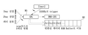
제어부(M1)는 ADC(M5)를 내부에 포함하고, ADC(M5)를 제1 내지 제6 전압센서(V1~6)에 의해 감지된 제1 및 제2 전원의 3상 전압값(R, S, T) 및 제1 내지 제3 전류센서(CT1~3)에 의해 계통 부하전원의 3상 전류값을 순차적으로 입력받을 수 있다. 이와 달리, ADC(M5)는 제어부(M1)의 외부에 구비될 수도 있다.The control unit M1 includes the ADC M5 and the ADC M5 is controlled by the three-phase voltage values R and R of the first and second power sources sensed by the first through sixth voltage sensors V1 through V6, S, T) and the first to third current sensors CT1 to CT3 can sequentially receive the three-phase current values of the system load power. Alternatively, the ADC M5 may be provided outside the control unit M1.
도 3과 같이, ADC(M5)는 제1 및 제2 전원의 3상 전압값과 계통 부하전원의 3상 전류값을 각기 입력받는 복수의 채널(예컨대, 9채널)을 포함하고, 일정시간 단위로 9채널을 순차적으로 스캔하여 각 채널로 입력된 정보를 디지털 변환하여 제어부(M1)로 전달한다. As shown in FIG. 3, the ADC M5 includes a plurality of channels (for example, 9 channels) receiving three-phase voltage values of the first and second power sources and three-phase current values of the system load power source, And sequentially converts the information input to each channel to the control unit M1.
그러면, 제어부(M1)는 디지털 변환된 제1 및 제2 전원의 3상 전압값과 계통 부하전원의 3상 전류값을 순차적으로 입력받아, 저장부(M3)에 저장할 수 있다. Then, the controller M1 sequentially receives the three-phase voltage values of the digitally-converted first and second power sources and the three-phase current value of the system load power source, and stores them in the storage unit M3.
>> 계통 전원 간 전환 기능>> Switching between system power
제어부(M1)는 주전원인 제1 전원을 사용중에 제1 내지 제3 전류센서(CT1~3)에 의해 제1 전원의 3상선로 중 적어도 하나의 선로에 전류 결상을 감지하면, 제1 내지 제6 스위치(SW1~6)를 제어하여 공통 3상선로에 예비전원인 제2 전원이 공급되도록 한다. 여기서, 제어부(M1)는 주전원의 전류 결상이 없으면, 주전원을 지속적으로 공통 3상선로에 공급한다.When the first to third current sensors CT1 to CT3 detect the current image formation on at least one of the three-phase line of the first power source during the use of the first power source as the main power source, 6 switches SW1 to SW6 to supply the second power source, which is a standby power source, to the common three-phase line. Here, if there is no current image formation in the main power source, the control unit M1 continuously supplies the main power source to the common three-phase line.
또한, 제어부(M1)는 예비전원인 제2 전원을 사용중에 제1 내지 제3 전압센서(VT1~3)의 감지정보에 의해 제1 전원의 복전을 감지하면, 제1 내지 제6 스위치(SW1~6)를 제어하여 공통 3상선로에 주전원인 제1 전원이 다시 공급되도록 한다. 이와 같이, 본 발명에서는 2회선의 독립되는 한전 전력을 공급받는 수용가에서 2중 모선 중 하나에 정전이 발생하는 국소 정전시에 대비할 수 있다. When the control unit M1 senses that the first power source is turned on by the detection information of the first to third voltage sensors VT1 to VT3 during use of the second power source as the standby power source, To 6) so that the first power source, which is the main power source, is supplied again to the common three-phase line. As described above, in the present invention, it is possible to prepare for a local power failure in which a power failure occurs in one of double buses in a customer who is supplied with two lines of uninterruptible power supply.
제어부(M1)는 상용 전원의 주파수 기준으로 8주기 이내에 주전원에서 예비전원으로 전원 전환을 수행할 수 있다.The control unit M1 can perform power switching from the main power source to the standby power source within 8 cycles based on the frequency of the commercial power source.
>> 비상 전원 전환 기능>> Emergency Power Switching Function
그런데, 광역 정전시에 2중 모선(제1 및 제2 전원) 모두에 정전이 발생하므로, 모선 간의 전원을 전환하더라도 정전의 단축을 기대할 수 있다. 본 발명에서는 이러한 경우에 대비하여 비상 발전기(EV)를 구비하고, 두 모선의 정전시에 비상 전원을 이용하여 정전 시간을 줄일 수 있다. 이하에서 설명한다.However, since a blackout occurs in both of the double buses (first and second power sources) at the time of the wide-area power interruption, shortening of the blackout can be expected even when the power between the bus lines is switched. In the present invention, the emergency generator (EV) is provided in case of such a case, and the power failure time can be reduced by using the emergency power source in case of power failure of the two bus bars. This will be described below.
제어부(M1)는 예비전원인 제2 전원을 사용중에 제1 전원이 복전되지 않은 상태로 제2 전원의 적어도 하나의 선로에 전류 결상을 감지하면, 제7 스위치(SW7)를 제어하여 부하의 전원선에 비상 전원을 공급한다. When the control unit M1 senses current image formation on at least one line of the second power source while the first power source is not being used during the use of the second power source as the standby power source, the control unit M1 controls the seventh switch SW7, Provide emergency power to the line.
여기서, 제어부(M1)는 제1 내지 제3 전압센서(VT1~3)에 의해 감지된 3상전압 값에 의해 제1 전원이 복전되지 않음을 감지하고, 제1 내지 제3 전류센서(CT1~3)에 의한 감지정보를 이용하여 제2 전원의 적어도 하나의 선로에 대한 전류 결상을 감지할 수 있다. The controller M1 detects that the first power source is not recovered by the three-phase voltage values sensed by the first to third voltage sensors VT1 to VT3 and the first to third current sensors CT1 to CT3, 3 senses current imaging of at least one line of the second power source.
이때, 제어부(M1)는 비상 전원으로 전환되는 전후 기설정된 시간동안 제1 및 제2 전원의 상별 전압, 계통 부하전원의 상별 전류 및 제1 내지 제6 스위치(SW1~6)의 접점, 제7 스위치(SW1)의 접점 및 비상 전원의 전압 등을 더 저장부(M3)에 기록할 수 있다. 이때, 제어부(M1)는 각 스위치의 접점을 제어하므로, 그 접정정보를 알 수 있다. 또한, 비상 전원의 전압은 별도의 전압 센서(미도시)에 의해 더 감지될 수 있다.At this time, the controller M1 controls the phase voltages of the first and second power sources, the currents of the phases of the system load power, the contacts of the first to sixth switches SW1 to SW6, The contact of the switch SW1 and the voltage of the emergency power source can be further recorded in the storage section M3. At this time, the controller M1 controls the contacts of the switches, so that the coordination information can be known. Further, the voltage of the emergency power source can be further sensed by a separate voltage sensor (not shown).
제어부(M1)는 제1 및 제2 전원이 정전될 경우에는 기설정된 시간(예컨대, 10초)내에 공급 전원선에 비상 발전기(EV)로부터의 비상 전원을 바로 인가시킬 수 있다. 여기서, 제어부(M1)는 제1 및 제2 전원이 부하의 전원선에 영향을 주는 것을 완전히 차단할 수 있게 제1 내지 제6 스위치(SW1~6)를 개방시킬 수 있다.The control unit M1 can directly apply the emergency power from the emergency generator EV to the power supply line within a predetermined time (e.g., 10 seconds) when the first and second power supplies are turned off. Here, the control unit M1 can open the first to sixth switches SW1 to SW6 so that the first and second power sources can completely block the power source line of the load.
다만, 제어부(M1)는 비상 발전기(EV)의 시운전시, 부하 절체 작업시이나, 제1 또는 제2 전원과 비상 전원을 병렬로 공급 전원선에 공급할 경우에는 비상 발전기(EV)를 미리 가동시켜 비상 전원에 정전압 정주파수가 확립되고 한전 전원과 비상 전원의 동기가 확립되면, 비상 전원을 공급할 수도 있다.However, the control unit M1 may operate the emergency generator EV in advance in case of trial operation of the emergency generator EV, load switching operation, or supplying the first or second power source and the emergency power source in parallel to the supply power source line, When the constant voltage constant frequency is established at the power source and the synchronization between the electric power source and the emergency power source is established, the emergency power source may be supplied.
제어부(M1)는 비상 전원의 사용중에 제1 전원 및 제2 전원 중 적어도 하나가 복전되면, 제1 내지 제6 스위치(SW1~6) 중 대응하는 스위치를 단락시켜 복전된 전원을 공통 3상선로에 공급한다.When at least one of the first power source and the second power source is recovered during use of the emergency power source, the control unit M1 short-circuits the corresponding one of the first to sixth switches SW1 to SW6, .
>> 전환 기록 기능>> Conversion history function
제어부(M1)는 제1 전원에서 제2 전원으로의 전환 동작시 또는 제2 전원에서 제1 전원으로의 전환 동작시에, 전환 동작 전후의 기설정된 시간(예컨대, 1초)동안 제1 내지 제6 전압센서(VT1~6) 및 제1 내지 제3 전류센서(CT1~3)의 감지정보를 참조하여 제1 및 제2 전원의 상별 전압, 계통 부하전원의 상별 전류, 제1 내지 제6 스위치(SW1~6)의 접점 및 제1 및 제2 전원 간의 전환 시간을 저장부(M3)에 기록한다. 여기서, 전환 시간은 제1 및 제2 전원 중 일 전원의 공급 중단시점 이후에 일 전원과 다른 타 전원이 공급되는데 소요되는 시간일 수 있다.The control unit M1 may control the first to the third power supplies for a predetermined time (for example, one second) before and after the switching operation in the switching operation from the first power source to the second power source or in the switching operation from the second power source to the first power source 6 voltage sensors VT1 to 6 and the first to third current sensors CT1 to CT3, the voltage of the first and second power sources, the current of the system load power source, To the storage unit M3, the switching time between the contact points of the switches SW1 to SW6 and the first and second power sources. Here, the switching time may be a time required for supplying a different power from the one power source after the power source of the first and second power sources is stopped.
제어부(M1)는 제1 전원 또는 제2 전원에서 비상 전원으로의 전환 동작시에 제7 스위치(SW7)의 접점 정보, 비상 전원의 전압 정보 및 시간 전원으로의 전환 시간을 저장부(M3)에 더 기록할 수 있다. The control unit M1 controls the switching unit M3 to switch the contact information of the seventh switch SW7, the voltage information of the emergency power source, and the time power to the time power source in the switching operation from the first power source or the second power source to the emergency power source You can record more.
또한, 제어부(M1)는 부팅 동작 후 최초의 10초의 제1 및 제2 전원의 상별 전압과 공통 전원의 전류 파형을 저장부(M3)에 더 기록할 수 있다.In addition, the controller M1 may further record the current waveforms of the first and second power sources of the first 10 seconds and the common power source in the storage unit M3 after the booting operation.
여기서, 저장부(M3)는 자동 부하 전환 개폐 장치의 외부에 구비된 것일 수 있다. 또한, 제어부(M1)는 내부 저장부(M3)에 전술한 기록 정보를 저장할 때, 그중 적어도 일부를 통신부(M2)를 통해 외부 단말에 전달할 수도 있다.Here, the storage unit M3 may be provided outside the automatic load switching device. When storing the above-described record information in the internal storage M3, the control unit M1 may transmit at least a part of the record information to the external terminal through the communication unit M2.
>> 부하 측 결상 경고 기능>> Load side phase loss warning function
한편, 제1 내지 제3 전류센서(CT1~3)는 부하측에 설치되어, 실제 한전 전원의 결상이 아니라, 수용가의 부하 측의 결상이라도, 주전원에서 예비전원으로 전환 동작한다. 그런데, 부하 측의 결상이면, 예비전원으로 전환 동작하여도 다시 전류 결상이 발생한다. 다시 말해, 부하측의 전류 결상이면, 주전원 및 예비전원의 어디로 전환해도 결상 상태가 유지된다. 한편, ALTS(Auto Load Transfer Switch)는 대부분 모터 차지(Motor Charge) 방식을 사용하므로 구체 차지 방식별로 다소 차이는 있지만, 약 10초 내지 20초의 차지 시간이 필요하다. 따라서, 부하측의 전류 결상으로 전술한 연속 전환 동작하면, 원인을 알지 못하는 정전 상황이 이어진다.On the other hand, the first to third current sensors CT1 to CT3 are provided on the load side so as to switch from the main power source to the standby power source, even if the image is formed on the load side of the customer. However, in the case of image formation on the load side, current image formation occurs again even after switching to the standby power source. In other words, in the case of the current image formation on the load side, the phase-lag state is maintained regardless of switching to the main power source and the standby power source. On the other hand, since the ALTS (Auto Load Transfer Switch) uses a motor charge method, a charge time of about 10 seconds to 20 seconds is required although there is a slight difference depending on the specific charge method. Therefore, when the above-described continuous switching operation is performed by current image formation on the load side, there occurs a power failure situation in which the cause is not known.
이러한 문제를 방지하고자, 본 발명에 따른 제어부(M1)는 제2 전원의 사용중 제1 전원의 복전을 감지하고, 제1 전원으로 재전환되었는데 수분내에 다시 전류 결상을 감지하면, 제어부(M1)는 부하 측의 전류 결상인 것으로 판단하고 더 이상의 전환 동작을 중단(Lock)한다.In order to prevent such a problem, the control unit M1 according to the present invention senses the first power source during the use of the second power source, and when the second power source is again switched to the first power source, It is determined that the current is a current image on the load side and the further switching operation is interrupted (Locked).
이때, 제어부(M1)는 예컨대, "Open Phase I Lock"와 같은 부하 측 전류 결상을 알리는 경고문을 표시부(M5)에 표시하고, 통신부(M2)를 통해 관리자에게 부하 측 전류 결상을 알릴 수 있다.At this time, the control unit M1 may display a warning message on the display unit M5 to notify the load side current image formation such as "Open Phase I Lock ", for example, and notify the manager of the load side current image formation through the communication unit M2.
제어부(M1)는 실시간 운영체계인 RTOS를 적용하여 감시, 제어, 통신, 표시나, 자원관리 등의 각 기능의 우선순위를 제어함에 따라 각 기능을 효과적으로 동작시킬 수 있다. The control unit M1 can effectively operate each function by controlling priorities of respective functions such as monitoring, control, communication, display, and resource management by applying RTOS, which is a real-time operating system.
구체적으로, 제어부(M1)는 하기의 표 1과 같이 어떤 상태에서도 계전과 제어를 우선적으로 처리하도록 각 기능 실행의 우선순위를 제어할 수 있다.Specifically, the control unit M1 can control the priority of each function execution so as to preferentially process the relay and control in any state as shown in Table 1 below.

배터리(Bat)는 계통 부하전원 및 비상 전원 중 적어도 하나의 전원에 의해 충전되며, 제어부(M1), 제1 내지 제6 전압센서(V1~6), 제1 내지 제3 전류센서(CT1~3) 및 통신부(M2) 등의 자동 부하 전환 개폐 장치의 각 구성요소의 동작 전원을 제공한다.The battery Bat is charged by a power source of at least one of a system load power source and an emergency power source and is connected to a control unit M1, first to sixth voltage sensors V1 to V6, first to third current sensors CT1 to CT3 ) And the communication section (M2) of the automatic load switching device.
한편, 전술한 예에서는 제1 및 제2 전원의 전류 결상시에 비상 전원을 이용하는 경우를 예로 들어 설명하였다. 하지만, 이와 달리, 태양광 발전 등의 자가 발전 시스템에 의해 생성된 비상 전원은 평상시의 부하 분담에도 이용될 수 있다.On the other hand, in the above-described example, the case where the emergency power source is used at the time of current imaging of the first and second power sources has been described as an example. Alternatively, however, the emergency power generated by the self-generating system, such as photovoltaic power generation, can be used for normal load sharing.
또한, 전술한 예에서는 제어부(M1)가 자동으로 계통 전원 간의 전환과 비상 전원으로의 전환을 수행하는 경우를 예로 들어 설명하였다. 하지만, 수동 제어가 선택된 경우에는 제어부(M1)는 표시부(M5) 또는 통신부(M2)를 통해 에러나 동작상태 정보를 관리자에게 알려주고, 관리자의 수동 조작에 따라 계통 전원 간의 전환과 비상 전원으로의 전환을 수행할 수도 있다.
In the above example, the control unit M1 automatically switches between the grid power sources and switches to the emergency power source. However, when the manual control is selected, the control unit M1 notifies the manager of the error or operation state information through the display unit M5 or the communication unit M2, and switches between the system power supply and the emergency power supply . ≪ / RTI >
이와 같이, 본 발명의 실시예는 제1 및 제2 전원과 비상 전원의 병렬 전원 제공 및 부하 상태 감지 결과를 이용해 공급 전원을 제1 전원, 제2 전원 또는 비상 전원으로 자동 전환할 수 있어, 전원 문제 발생시에 정전 시간을 단축할 수 있다. 그에 따라, 본 발명에서는 사고 원인 분석과 원상 복구 분석을 설비 관리자의 수동 측정과 판단에 의지함에 따라 과도한 비상 발전기가 사용되거나 추가 정전 손실이 발생하던 종래의 문제를 개선할 수 있다.As described above, according to the embodiment of the present invention, the supply power can be automatically switched to the first power source, the second power source, or the emergency power source by using the parallel power supply of the first and second power sources and the emergency power source, The power failure time can be shortened when a problem occurs. Accordingly, the present invention relieves the conventional problem that an excessive emergency generator is used or an additional power loss occurs due to the manual measurement and judgment of the cause analysis and the restoration analysis by the facility manager.
또한, 본 발명의 실시예는 2중 모선(제1 및 제2 전원) 모두에 정전이 발생하는 광역 정전시 또는 계약 전력 부족으로 최대 사용 전력 도달시에, 비상 전원을 공급할 수 있어, 정전 시간을 줄일 수 있다. In addition, the embodiment of the present invention can supply the emergency power supply at the time of the wide-area power outage in which a power failure occurs in both of the double buses (first and second power sources) or when the maximum use power is reached due to contract power shortage, Can be reduced.
뿐만 아니라, 본 발명의 실시예는 전원 전환시에 전력 정보 기록을 제공하여 사고 원인과 동작 근거를 제공하여 관리자의 빠른 의사결정을 도울 수 있고, 전력 공급 손실을 가급적 줄일 수 있다.In addition, the embodiment of the present invention can provide power information recording at the time of power switching to provide an accident cause and an operation reason, thereby helping the manager to make quick decisions and reducing power supply loss as much as possible.
더불어, 본 발명의 실시예는 제1 전원과 제2 전원의 전류 결상이 아닌 부하 측의 전류 결상으로 인해 연속으로 전환 동작하는 문제를 방지할 수 있어, 수용가의 정전 피해를 줄이고 제품 메커니즘을 보호할 수 있다.
In addition, the embodiment of the present invention can prevent the problem of continuous switching operation due to the current image formation on the load side rather than the current image formation between the first power source and the second power source, thereby reducing the power failure of the consumer and protecting the product mechanism .
이하, 도 4를 참조하여 본 발명의 실시예에 따른 자동 부하 전환 개폐 제어 방법에 대하여 설명한다. 도 4는 본 발명의 실시예에 따른 자동 부하 전환 개폐 제어 방법을 도시한 흐름도이다.Hereinafter, an automatic load switching control method according to an embodiment of the present invention will be described with reference to FIG. 4 is a flowchart illustrating an automatic load switching on / off control method according to an embodiment of the present invention.
도 4를 참조하면, 제어부(M1)는 계통 부하전원으로 주전원(제1 전원)을 사용하면서, 제1 내지 제3 전류센서(CT1~3)에 의한 상별 전류값을 이용하여 제1 전원의 3상선로 중 적어도 하나의 선로에 전류 결상 여부를 모니터링한다(S410).Referring to FIG. 4, the controller M1 uses the main current source (first power source) as the system load power, while using the current value by the first to third current sensors CT1 to CT3, At least one line of the commercial line is monitored for the current image formation (S410).
전류 결상 감지시에 제어부(M1)는 제1 내지 제3 스위치(SW1~3)을 개방시키고, 제4 내지 제6 스위치(SW4~6)를 단락시켜 공통 3상선로에 예비전원(제2 전원)을 공급하고, 전환 기록을 저장부(M3)에 저장시킨다(S420). 상세하게는, 제어부(M1)는 공통 3상선로에 제2 전원을 공급한 전후 기설정된 시간(예컨대, 1초)동안 제1 내지 제6 전압센서(V1~V6) 및 제1 내지 제3 전류센서(CT1~3)의 감지정보를 참조하여 제1 및 제2 전원의 상별 전압, 계통 부하전원의 상별 전류 및 제1 내지 제6 스위치(SW1~6)의 접점을 저장부(M3)에 기록할 수 있다.The control section M1 opens the first to third switches SW1 to SW3 and short-circuits the fourth to sixth switches SW4 to SW6 to detect the presence of the standby power source And stores the switching record in the storage unit M3 (S420). More specifically, the control section M1 controls the first through sixth voltage sensors V1 through V6 and the first through third currents V1 through V6 for a predetermined time (for example, 1 second) before and after the second power source is supplied to the common three- By referring to the detection information of the sensors CT1 to CT3, the voltage of the first and second power sources, the current of the grid load power source, and the contacts of the first to sixth switches SW1 to SW6 are written to the storage unit M3 can do.
제어부(M1)는 계통 부하전원을 제2 전원으로 전환시킨 후 제1 전원의 복전 여부 및 제2 전원의 결상 여부를 모니터링한다(S430~S440)). 이때, 제어부(M1)는 제1 내지 제3 전압센서(VT1~3)에 의해 감지된 제1 전원의 상별 전압값을 이용하여 제1 전원의 복전 여부를 확인할 수 있다. 또한, 제어부(M1)는 제1 내지 제3 전류센서(CT1~3)에 의한 상별 전류값을 이용하여 제2 전원의 3상선로 중 적어도 하나의 선로에 전류 결상 여부를 모니터링한다.The control unit M1 monitors whether the first power source is turned on and whether the second power source is turned on after switching the system load power source to the second power source (S430 to S440). At this time, the controller M1 may check whether the first power source is turned on by using the voltage value of the first power source sensed by the first to third voltage sensors VT1 to VT3. Further, the controller Ml monitors whether or not current is established in at least one of the three-phase line of the second power source by using the current value by the first to third current sensors CT1 to CT3.
제어부(M1)는 제1 전원이 복전되면(S430의 예), 계통 부하전원을 제1 전원으로 전환시키고, 전환 기록을 저장부(M3)에 저장시킨다(S450). 상세하게는, 제어부(M1)는 제1 전원으로 전환하는 전후의 기설정된 시간 동안 제1 및 제2 전원의 상별 전압, 계통 부하전원의 상별 전류 및 제1 내지 제6 스위치(SW1~6)의 접점을 저장부(M3)에 기록할 수 있다.If the first power source is restored (YES in S430), the control unit M1 switches the system load power source to the first power source and stores the switching record in the storage unit M3 (S450). Specifically, the controller M1 controls the phase voltages of the first and second power sources, the currents of the phases of the system load power, and the currents of the first to sixth switches SW1 to SW6, respectively, for a predetermined time before and after switching to the first power source The contact point can be recorded in the storage section M3.
여기서, 제어부(M1)는 제1 전원으로 재전환되었는데 수분 내에 다시 전류 결상을 감지하면, 제어부(M1)는 부하 측의 전류 결상인 것으로 판단하고 더 이상의 전환 동작을 중단(Lock)하고, 부하 측 전류 결상을 알리는 경고문을 표시부(M5)에 표시할 수 있다.If the controller M1 detects the current image formation again within a few minutes, the control unit M1 determines that the image is a current image on the load side, stops the further switching operation, locks the load side A warning message indicating the current image formation can be displayed on the display section M5.
제어부(M1)는 제1 전원이 복전되지 않았는데, 제2 전원에 결상이 발생하면(S440의 예), 비상 발전기(EV)로부터 생성된 비상 전원을 부하의 전원선에 공급하고, 전환 기록을 저장부(M3)에 저장시킨다(S460). The control unit M1 supplies the emergency power generated from the emergency generator EV to the power line of the load and stores the switching record when the image forming operation has occurred in the second power source (S440) And stores it in the unit M3 (S460).
이때, 제어부(M1)는 비상 전원을 부하의 전원선에 공급하지 않은 경우, 제7 스위치(SW7)를 단락시켜 비상 전원을 부하의 전원선에 공급한다. 또한, 비상 전원와 계통 부하전원으로부터의 공급 전원을 병렬로 부하의 전원선에 공급하던 경우에는 별도의 스위치 제어를 수행하지 않거나, 제1 내지 제6 스위치(SW1~6)만을 개방시킬 수 있다. 또한, 제어부(M1)는 비상 전원으로 전원을 전환한 전후 기설정된 시간동안 제1 및 제2 전원의 상별 전압, 계통 부하전원의 상별 전류 및 제1 내지 제6 스위치(SW1~6)의 접점, 비상전원의 전압 및 제7 스위치(SW1)의 접점 중 적어도 하나를 저장부(M3)에 기록할 수 있다.At this time, when the emergency power source is not supplied to the power source line of the load, the control unit M1 short-circuits the seventh switch SW7 to supply the emergency power source to the power source line of the load. In addition, when supplying power from the emergency power source and the system load power source to the load power line in parallel, no separate switch control is performed or only the first to sixth switches SW1 to SW6 can be opened. In addition, the control unit M1 controls the phase voltages of the first and second power sources, the currents of the phases of the system load power source, and the contacts of the first to sixth switches SW1 to SW6, for the predetermined time before and after the power source is switched to the emergency power source, It is possible to record at least one of the voltage of the emergency power source and the contact of the seventh switch SW1 in the storage section M3.
제어부(M1)는 비상 전원의 공급중에 제1 및 제2 전원 중 하나가 복전여부를 모니터링한다(S470). 이때, 제어부(M1)는 제1 내지 제6 전압센서(V1~V6)의 감지정보를 이용하여 제1 및 제2 전원 중 하나의 복전 여부를 판단할 수 있다.The controller M1 monitors whether one of the first and second power supplies is turned on during the supply of the emergency power (S470). At this time, the controller Ml may determine whether one of the first and second power supplies is turned on by using the sensing information of the first to sixth voltage sensors V1 to V6.
제1 및 제2 전원 중 하나가 복전되면, 제어부(M1)는 복전된 전원을 계통 부하전원으로 공급한다(S480). 이때, 제어부(M1)는 제1 전원 및 제2 전원이 둘다 복전된 경우, 주전원인 제1 전원을 우선적으로 계통 부하전원으로 공급할 수 있다. 또한, 복전된 전원이 제2 전원인 경우, 제1 전원의 복전을 모니터링하고, 제1 전원이 복전되면, 계통 부하전원을 제1 전원으로 전환시키는 동작을 더 수행할 수 있다.When one of the first and second power supplies is recovered, the controller Ml supplies the recovered power to the system load power (S480). At this time, when both the first power source and the second power source are restored, the control unit M1 may preferentially supply the first power source, which is the main power source, to the system load power source. In addition, when the recovered power source is the second power source, monitoring of the first power source is performed, and when the first power source is recovered, the operation of switching the system load power source to the first power source can be further performed.
이와 같이, 본 발명의 실시예는 부하 상태 감지 결과를 이용해 공급 전원을 제1 전원, 제2 전원 또는 비상 전원으로 자동 전환할 수 있어, 전원 문제 발생시에 정전 시간을 단축할 수 있다.As described above, according to the embodiment of the present invention, the power supply can be automatically switched to the first power source, the second power source, or the emergency power source by using the load state detection result, so that the power failure time can be shortened when the power source trouble occurs.
또한, 본 발명의 실시예는 2중 모선(제1 및 제2 전원) 모두에 정전이 발생하는 광역 정전시 또는 계약 전력 부족으로 최대 사용 전력 도달시에, 비상 전원을 공급할 수 있어, 정전 시간을 줄일 수 있다. In addition, the embodiment of the present invention can supply the emergency power supply at the time of the wide-area power outage in which a power failure occurs in both of the double buses (first and second power sources) or when the maximum use power is reached due to contract power shortage, Can be reduced.
뿐만 아니라, 본 발명의 실시예는 전원 전환시에 전력 정보 기록을 제공하여 사고 원인과 동작 근거를 제공하여 관리자의 빠른 의사결정을 도울 수 있고, 전력 공급 손실을 가급적 줄일 수 있다.In addition, the embodiment of the present invention can provide power information recording at the time of power switching to provide an accident cause and an operation reason, thereby helping the manager to make quick decisions and reducing power supply loss as much as possible.
더불어, 본 발명의 실시예는 제1 전원과 제2 전원의 전류 결상이 아닌 부하 측의 전류 결상으로 인해 연속으로 전환 동작하는 문제를 방지할 수 있어, 수용가의 정전 피해를 줄이고 제품 메커니즘을 보호할 수 있다.
In addition, the embodiment of the present invention can prevent the problem of continuous switching operation due to the current image formation on the load side rather than the current image formation between the first power source and the second power source, thereby reducing the power failure of the consumer and protecting the product mechanism .
이상, 본 발명의 구성에 대하여 첨부 도면을 참조하여 상세히 설명하였으나, 이는 예시에 불과한 것으로서, 본 발명이 속하는 기술분야에 통상의 지식을 가진자라면 본 발명의 기술적 사상의 범위 내에서 다양한 변형과 변경이 가능함은 물론이다. 따라서 본 발명의 보호 범위는 전술한 실시예에 국한되어서는 아니되며 이하의 특허청구범위의 기재에 의하여 정해져야 할 것이다.While the present invention has been described in detail with reference to the accompanying drawings, it is to be understood that the invention is not limited to the above-described embodiments. Those skilled in the art will appreciate that various modifications, Of course, this is possible. Accordingly, the scope of protection of the present invention should not be limited to the above-described embodiments, but should be determined by the description of the following claims.
Claims (9)
상기 복수의 스위치의 일단에 연결되어 상기 제1 전원 및 제2 전원의 상별 전압을 검출하는 복수의 전압센서;
상기 제1 전원과 제2 전원에 공통으로 연결되는 공통 3상선로에 연결되는 상기 복수의 스위치의 타단에서 변압기를 거쳐 부하에 공급되는 계통 부하전원의 상별 전류를 검출하는 3개의 전류센서; 및
상기 전류센서에 의한 감지정보를 이용하여 상기 제1 전원의 3상선로 중 적어도 하나의 선로에 전류 결상을 감지하고, 전류 결상 감지시에 상기 복수의 스위치를 제어하여 상기 공통 3상선로에 상기 제2 전원을 공급하며, 상기 제2 전원을 공급한 전후 기설정된 시간동안 상기 복수의 전압센서 및 상기 전류센서의 감지정보를 참조하여 상기 제1 및 제2 전원의 상별 전압, 상기 상별 전류, 상기 복수의 스위치의 접점 및 전환 시간을 저장부에 기록하는 제어부
를 포함하는 자동 부하 전환 개폐 장치.A plurality of switches each connected in series to a three-phase line of a first power source and a second power source that replaces the first power source;
A plurality of voltage sensors connected to one ends of the plurality of switches to detect respective voltages of the first power source and the second power source;
Three current sensors for detecting currents in different phases of the system load power supplied to the load through the transformer from the other end of the plurality of switches connected to the common three-phase line connected in common to the first power source and the second power source; And
Detecting a current image formation on at least one of the three-phase line of the first power source by using the detection information by the current sensor, and controlling the plurality of switches at the time of detecting the current image formation, 2, and the phase voltage of the first and second power supplies, the current of the first phase, the phase current of the second power source, and the phase current of the first power source are referred to by sensing information of the plurality of voltage sensors and the current sensor for a predetermined time before and after supplying the second power source And a control unit
And an automatic load switching device.
비상 전원을 생성하는 비상 발전기; 및
상기 제어부의 제어에 따라 상기 부하의 전원선에 상기 계통 부하전원으로부터 생성된 전원 또는 상기 비상 전원을 선택적으로 제공하는 비상 제어용 스위치를 더 포함하고,
상기 제어부는, 상기 복수의 전압센서와 상기 전류센서에 의해 상기 제1 및 제2 전원의 모두에 결상 발생을 감지하면, 상기 비상 제어용 스위치를 제어하여 상기 부하의 전원선에 상기 비상 전원을 공급하는 것인 자동 부하 전환 개폐 장치.The method according to claim 1,
An emergency generator generating an emergency power source; And
Further comprising an emergency control switch for selectively supplying power generated from the system load power source or the emergency power source to the power source line of the load under the control of the control unit,
Wherein the control unit controls the emergency control switch to supply the emergency power source to the power line of the load when the voltage sensor and the current sensor detect occurrence of an image formation in both of the first and second power sources Automatic load switching device.
상기 비상 전원을 공급한 전후에 상기 비상 제어용 스위치의 접점 정보 및 상기 비상 전원의 전압 중 적어도 하나를 상기 저장부에 더 기록하는 것인 자동 부하 전환 개폐 장치.3. The apparatus of claim 2,
Wherein at least one of the contact information of the emergency control switch and the voltage of the emergency power source is further recorded in the storage section before and after the supply of the emergency power source.
상기 제2 전원을 공급한 후 상기 복수의 전압센서에 의해 상기 제1 전원의 복전 여부를 감지하고, 상기 제1 전원의 복전시에 상기 복수의 스위치를 제어하여 상기 공통 3상선로에 상기 제1 전원을 공급하며,
상기 제1 전원을 재공급한 전후 상기 기설정된 시간동안 상기 복수의 전압센서 및 상기 전류센서의 감지정보에 의해 상기 제1 및 제2 전원의 상별 전압, 상기 상별 전류, 상기 복수의 스위치의 접점 및 상기 제2 전원에서 상기 제1 전원으로의 전환 시간을 저장부에 기록하는 것인 자동 부하 전환 개폐 장치.The apparatus of claim 1,
And a second power source for supplying power to the first power source, the second power source for supplying power to the second power source, the second power source for supplying power to the second power source, Power supply,
The currents of the first and second power sources, the currents of the plurality of switches, the contacts of the plurality of switches, and the currents of the first and second power sources by the sensing information of the plurality of voltage sensors and the current sensor for a predetermined time before and after the first power source is re- And writes the switching time from the second power source to the first power source to the storage unit.
상기 제1 전원을 재공급한 후에 상기 제1 전원의 전류 결상 발생시에 부하측에 전류 결상이 발생한 것으로 판단하고, 표시부에 기설정된 부하측 전류 결상을 경고하는 경고를 표시하는 것인 자동 부하 전환 개폐 장치.5. The apparatus of claim 4,
And a warning is displayed to warn the display unit of a predetermined load side current image formation when it is determined that a current image is formed on the load side at the time of current image formation of the first power source after the first power source is re-supplied.
복수의 채널에 의해 상기 복수의 전압센서의 감지정보 및 상기 전류센서의 감지정보를 순차적으로 입력받아 디지털 변환하는 ADC를 더 포함하고,
상기 제어부는, 상기 ADC에 의해 디지털 변환된 감지정보를 순차적으로 상기 저장부에 저장하는 것인 자동 부하 전환 개폐 장치.The method according to claim 1,
Further comprising: an ADC for sequentially receiving and digitally converting detection information of the plurality of voltage sensors and detection information of the current sensor by a plurality of channels,
Wherein the control unit sequentially stores the sensed information digitally converted by the ADC in the storage unit.
상기 전류센서에 의한 감지정보를 이용하여 상기 제1 전원의 3상선로 중 적어도 하나의 선로에 전류 결상을 감지하는 단계;
전류 결상 감지시에 상기 복수의 스위치를 제어하여 상기 공통 3상선로에 상기 제2 전원을 공급하는 단계; 및
상기 제2 전원을 공급한 전후 기설정된 시간동안 상기 복수의 전압센서 및 상기 전류센서의 감지정보를 참조하여 상기 제1 및 제2 전원의 상별 전압, 상기 상별 전류, 상기 복수의 스위치의 접점 및 전환 시간을 저장부에 기록하는 단계
를 포함하는 자동 부하 전환 개폐 제어 방법.A plurality of switches connected in series to a three-phase line of a first power source and a second power source that replaces the first power source, and a plurality of switches connected to one end of the plurality of switches, A plurality of voltage sensors for detecting a current for each phase of the system load power supplied to the load via the transformer from the other end of the plurality of switches connected to the common three-phase line commonly connected to the first power source and the second power source, A method of controlling an automatic load switching control of a control unit using current sensors,
Sensing current image formation on at least one line of the three-phase line of the first power source using sensing information by the current sensor;
Controlling the plurality of switches to supply the second power to the common three-phase line when current imaging is detected; And
The currents of the first and second power sources, the currents of the plurality of switches, the switching points of the plurality of switches, and the switching of the plurality of switches by referring to the sensing information of the plurality of voltage sensors and the current sensor for a predetermined time before and after supplying the second power. Recording the time in the storage unit
Wherein the automatic load switching control method comprises:
상기 복수의 전압센서와 상기 전류센서에 의해 상기 제1 및 제2 전원의 모두에 이상 발생을 감지하면, 비상 제어용 스위치를 제어하여 비상 전원을 생성하는 비상 발전기의 출력인 비상 전원을 상기 부하의 전원선에 공급하는 단계
를 더 포함하는 자동 부하 전환 개폐 제어 방법.8. The method of claim 7,
When an abnormality is detected in both of the first and second power sources by the plurality of voltage sensors and the current sensor, an emergency power supply, which is an output of an emergency generator generating an emergency power by controlling the emergency control switch, Step to supply to line
Further comprising the steps of:
상기 비상 전원으로의 전환 동작시에 상기 비상 제어용 스위치의 접점 정보 및 상기 비상 전원의 전압 중 적어도 하나를 상기 저장부에 더 기록하는 단계
를 더 포함하는 자동 부하 전환 개폐 제어 방법.9. The method of claim 8,
Further comprising the step of recording at least one of the contact information of the emergency control switch and the voltage of the emergency power supply in the storage unit in the switching operation to the emergency power supply
Further comprising the steps of:
Priority Applications (1)
| Application Number | Priority Date | Filing Date | Title |
|---|---|---|---|
| KR1020150106312A KR20170013541A (en) | 2015-07-28 | 2015-07-28 | Apparatus and Control Method for Transferring Automatic Load Switch |
Applications Claiming Priority (1)
| Application Number | Priority Date | Filing Date | Title |
|---|---|---|---|
| KR1020150106312A KR20170013541A (en) | 2015-07-28 | 2015-07-28 | Apparatus and Control Method for Transferring Automatic Load Switch |
Publications (1)
| Publication Number | Publication Date |
|---|---|
| KR20170013541A true KR20170013541A (en) | 2017-02-07 |
Family
ID=58108079
Family Applications (1)
| Application Number | Title | Priority Date | Filing Date |
|---|---|---|---|
| KR1020150106312A Ceased KR20170013541A (en) | 2015-07-28 | 2015-07-28 | Apparatus and Control Method for Transferring Automatic Load Switch |
Country Status (1)
| Country | Link |
|---|---|
| KR (1) | KR20170013541A (en) |
Cited By (4)
| Publication number | Priority date | Publication date | Assignee | Title |
|---|---|---|---|---|
| KR101989774B1 (en) * | 2018-12-27 | 2019-06-17 | 주식회사 지엔이피에스 | Hybrid Closed Transition Transfer Switch System Using Mechanical And Electronic Switches |
| CN113131603A (en) * | 2021-04-21 | 2021-07-16 | 高奇 | Intelligent dual-power electronic fast converter and conversion method |
| CN114142572A (en) * | 2021-12-14 | 2022-03-04 | 广东可易亚半导体科技有限公司 | Power supply control circuit based on MOS switch circuit component |
| KR20230048748A (en) * | 2021-10-05 | 2023-04-12 | 한국전력공사 | Apparatus and Method for automatic voltage static switch with electronic type |
-
2015
- 2015-07-28 KR KR1020150106312A patent/KR20170013541A/en not_active Ceased
Cited By (4)
| Publication number | Priority date | Publication date | Assignee | Title |
|---|---|---|---|---|
| KR101989774B1 (en) * | 2018-12-27 | 2019-06-17 | 주식회사 지엔이피에스 | Hybrid Closed Transition Transfer Switch System Using Mechanical And Electronic Switches |
| CN113131603A (en) * | 2021-04-21 | 2021-07-16 | 高奇 | Intelligent dual-power electronic fast converter and conversion method |
| KR20230048748A (en) * | 2021-10-05 | 2023-04-12 | 한국전력공사 | Apparatus and Method for automatic voltage static switch with electronic type |
| CN114142572A (en) * | 2021-12-14 | 2022-03-04 | 广东可易亚半导体科技有限公司 | Power supply control circuit based on MOS switch circuit component |
Similar Documents
| Publication | Publication Date | Title |
|---|---|---|
| CN104348217B (en) | It is equipped with the energy-storage system and its driving method of the uninterrupted power source of battery | |
| JP2848554B2 (en) | System for supplying power to a device and method for evaluating the life and capacity of a power storage device | |
| US12224620B2 (en) | Power supply circuit and uninterruptible power supply ups system | |
| CN204538802U (en) | Middle pressure power transmission and distribution automatic switching control system | |
| CN113691010A (en) | Redundant power supply system and control method | |
| KR20170013541A (en) | Apparatus and Control Method for Transferring Automatic Load Switch | |
| JP5518926B2 (en) | Distribution automation system | |
| EP1465318A2 (en) | Uninterruptible power supply system | |
| EP3042429B1 (en) | Microgrid with redundant points of common coupling and control method for it, to reduce risk of microgrid's islanding | |
| CN112448375B (en) | Power supply automatic switching method, monitoring system and track medium-voltage ring network system | |
| CN102044978A (en) | Power supply circuit and monitoring protection method thereof | |
| WO2018105875A1 (en) | Power conversion apparatus and uninterruptible power supply comprising same | |
| JP2014128165A (en) | Insulation determination system | |
| JP2016054590A (en) | Vehicle charging system | |
| KR20170003334A (en) | Automatic load transfer switch and control method thereof | |
| CN103023029A (en) | Automatic parallel off and parallel control device for sectionalized power supply of single busbar | |
| JP5858236B2 (en) | Battery system | |
| RU2215355C1 (en) | No-break power installation for railway automatic-control systems | |
| JP2020108206A (en) | Charger and method for determining cause of abnormality in charger | |
| KR20180096090A (en) | Uninterruptible power supply system | |
| EP2903129B1 (en) | Multi-type and multi-mode automatic transfer switching apparatus and method thereof | |
| JP5662229B2 (en) | Transformer device for movement | |
| US20230187925A1 (en) | Electrical protection systems and methods having improved selectivity | |
| JP7458333B2 (en) | Uninterruptible power switching device, test equipment for uninterruptible power switching device | |
| CN117060521A (en) | A charged protection charging and discharging system and method for mobile power supply vehicles |
Legal Events
| Date | Code | Title | Description |
|---|---|---|---|
| A201 | Request for examination | ||
| PA0109 | Patent application |
Patent event code: PA01091R01D Comment text: Patent Application Patent event date: 20150728 |
|
| PA0201 | Request for examination | ||
| E902 | Notification of reason for refusal | ||
| PE0902 | Notice of grounds for rejection |
Comment text: Notification of reason for refusal Patent event date: 20161103 Patent event code: PE09021S01D |
|
| PG1501 | Laying open of application | ||
| E601 | Decision to refuse application | ||
| PE0601 | Decision on rejection of patent |
Patent event date: 20170605 Comment text: Decision to Refuse Application Patent event code: PE06012S01D Patent event date: 20161103 Comment text: Notification of reason for refusal Patent event code: PE06011S01I |