KR20170015257A - 압력 센서와 그 제조 공정 - Google Patents
압력 센서와 그 제조 공정 Download PDFInfo
- Publication number
- KR20170015257A KR20170015257A KR1020160097634A KR20160097634A KR20170015257A KR 20170015257 A KR20170015257 A KR 20170015257A KR 1020160097634 A KR1020160097634 A KR 1020160097634A KR 20160097634 A KR20160097634 A KR 20160097634A KR 20170015257 A KR20170015257 A KR 20170015257A
- Authority
- KR
- South Korea
- Prior art keywords
- evaluation unit
- circuit board
- pressure sensor
- sensor
- reinforcing members
- Prior art date
- Legal status (The legal status is an assumption and is not a legal conclusion. Google has not performed a legal analysis and makes no representation as to the accuracy of the status listed.)
- Granted
Links
Images




Classifications
-
- G—PHYSICS
- G01—MEASURING; TESTING
- G01L—MEASURING FORCE, STRESS, TORQUE, WORK, MECHANICAL POWER, MECHANICAL EFFICIENCY, OR FLUID PRESSURE
- G01L23/00—Devices or apparatus for measuring or indicating or recording rapid changes, such as oscillations, in the pressure of steam, gas, or liquid; Indicators for determining work or energy of steam, internal-combustion, or other fluid-pressure engines from the condition of the working fluid
- G01L23/08—Devices or apparatus for measuring or indicating or recording rapid changes, such as oscillations, in the pressure of steam, gas, or liquid; Indicators for determining work or energy of steam, internal-combustion, or other fluid-pressure engines from the condition of the working fluid operated electrically
- G01L23/10—Devices or apparatus for measuring or indicating or recording rapid changes, such as oscillations, in the pressure of steam, gas, or liquid; Indicators for determining work or energy of steam, internal-combustion, or other fluid-pressure engines from the condition of the working fluid operated electrically by pressure-sensitive members of the piezoelectric type
-
- G—PHYSICS
- G01—MEASURING; TESTING
- G01L—MEASURING FORCE, STRESS, TORQUE, WORK, MECHANICAL POWER, MECHANICAL EFFICIENCY, OR FLUID PRESSURE
- G01L1/00—Measuring force or stress, in general
- G01L1/16—Measuring force or stress, in general using properties of piezoelectric devices
-
- G—PHYSICS
- G01—MEASURING; TESTING
- G01L—MEASURING FORCE, STRESS, TORQUE, WORK, MECHANICAL POWER, MECHANICAL EFFICIENCY, OR FLUID PRESSURE
- G01L23/00—Devices or apparatus for measuring or indicating or recording rapid changes, such as oscillations, in the pressure of steam, gas, or liquid; Indicators for determining work or energy of steam, internal-combustion, or other fluid-pressure engines from the condition of the working fluid
- G01L23/22—Devices or apparatus for measuring or indicating or recording rapid changes, such as oscillations, in the pressure of steam, gas, or liquid; Indicators for determining work or energy of steam, internal-combustion, or other fluid-pressure engines from the condition of the working fluid for detecting or indicating knocks in internal-combustion engines; Units comprising pressure-sensitive members combined with ignitors for firing internal-combustion engines
- G01L23/221—Devices or apparatus for measuring or indicating or recording rapid changes, such as oscillations, in the pressure of steam, gas, or liquid; Indicators for determining work or energy of steam, internal-combustion, or other fluid-pressure engines from the condition of the working fluid for detecting or indicating knocks in internal-combustion engines; Units comprising pressure-sensitive members combined with ignitors for firing internal-combustion engines for detecting or indicating knocks in internal combustion engines
- G01L23/222—Devices or apparatus for measuring or indicating or recording rapid changes, such as oscillations, in the pressure of steam, gas, or liquid; Indicators for determining work or energy of steam, internal-combustion, or other fluid-pressure engines from the condition of the working fluid for detecting or indicating knocks in internal-combustion engines; Units comprising pressure-sensitive members combined with ignitors for firing internal-combustion engines for detecting or indicating knocks in internal combustion engines using piezoelectric devices
-
- G—PHYSICS
- G01—MEASURING; TESTING
- G01D—MEASURING NOT SPECIALLY ADAPTED FOR A SPECIFIC VARIABLE; ARRANGEMENTS FOR MEASURING TWO OR MORE VARIABLES NOT COVERED IN A SINGLE OTHER SUBCLASS; TARIFF METERING APPARATUS; MEASURING OR TESTING NOT OTHERWISE PROVIDED FOR
- G01D11/00—Component parts of measuring arrangements not specially adapted for a specific variable
- G01D11/24—Housings ; Casings for instruments
- G01D11/245—Housings for sensors
-
- G—PHYSICS
- G01—MEASURING; TESTING
- G01L—MEASURING FORCE, STRESS, TORQUE, WORK, MECHANICAL POWER, MECHANICAL EFFICIENCY, OR FLUID PRESSURE
- G01L19/00—Details of, or accessories for, apparatus for measuring steady or quasi-steady pressure of a fluent medium insofar as such details or accessories are not special to particular types of pressure gauges
- G01L19/04—Means for compensating for effects of changes of temperature, i.e. other than electric compensation
-
- G—PHYSICS
- G01—MEASURING; TESTING
- G01L—MEASURING FORCE, STRESS, TORQUE, WORK, MECHANICAL POWER, MECHANICAL EFFICIENCY, OR FLUID PRESSURE
- G01L19/00—Details of, or accessories for, apparatus for measuring steady or quasi-steady pressure of a fluent medium insofar as such details or accessories are not special to particular types of pressure gauges
- G01L19/14—Housings
- G01L19/142—Multiple part housings
-
- G—PHYSICS
- G01—MEASURING; TESTING
- G01L—MEASURING FORCE, STRESS, TORQUE, WORK, MECHANICAL POWER, MECHANICAL EFFICIENCY, OR FLUID PRESSURE
- G01L19/00—Details of, or accessories for, apparatus for measuring steady or quasi-steady pressure of a fluent medium insofar as such details or accessories are not special to particular types of pressure gauges
- G01L19/14—Housings
- G01L19/148—Details about the circuit board integration, e.g. integrated with the diaphragm surface or encapsulation
-
- G—PHYSICS
- G01—MEASURING; TESTING
- G01L—MEASURING FORCE, STRESS, TORQUE, WORK, MECHANICAL POWER, MECHANICAL EFFICIENCY, OR FLUID PRESSURE
- G01L23/00—Devices or apparatus for measuring or indicating or recording rapid changes, such as oscillations, in the pressure of steam, gas, or liquid; Indicators for determining work or energy of steam, internal-combustion, or other fluid-pressure engines from the condition of the working fluid
- G01L23/22—Devices or apparatus for measuring or indicating or recording rapid changes, such as oscillations, in the pressure of steam, gas, or liquid; Indicators for determining work or energy of steam, internal-combustion, or other fluid-pressure engines from the condition of the working fluid for detecting or indicating knocks in internal-combustion engines; Units comprising pressure-sensitive members combined with ignitors for firing internal-combustion engines
- G01L23/221—Devices or apparatus for measuring or indicating or recording rapid changes, such as oscillations, in the pressure of steam, gas, or liquid; Indicators for determining work or energy of steam, internal-combustion, or other fluid-pressure engines from the condition of the working fluid for detecting or indicating knocks in internal-combustion engines; Units comprising pressure-sensitive members combined with ignitors for firing internal-combustion engines for detecting or indicating knocks in internal combustion engines
- G01L23/225—Devices or apparatus for measuring or indicating or recording rapid changes, such as oscillations, in the pressure of steam, gas, or liquid; Indicators for determining work or energy of steam, internal-combustion, or other fluid-pressure engines from the condition of the working fluid for detecting or indicating knocks in internal-combustion engines; Units comprising pressure-sensitive members combined with ignitors for firing internal-combustion engines for detecting or indicating knocks in internal combustion engines circuit arrangements therefor
-
- G—PHYSICS
- G01—MEASURING; TESTING
- G01L—MEASURING FORCE, STRESS, TORQUE, WORK, MECHANICAL POWER, MECHANICAL EFFICIENCY, OR FLUID PRESSURE
- G01L23/00—Devices or apparatus for measuring or indicating or recording rapid changes, such as oscillations, in the pressure of steam, gas, or liquid; Indicators for determining work or energy of steam, internal-combustion, or other fluid-pressure engines from the condition of the working fluid
- G01L23/26—Details or accessories
-
- G—PHYSICS
- G01—MEASURING; TESTING
- G01L—MEASURING FORCE, STRESS, TORQUE, WORK, MECHANICAL POWER, MECHANICAL EFFICIENCY, OR FLUID PRESSURE
- G01L9/00—Measuring steady of quasi-steady pressure of fluid or fluent solid material by electric or magnetic pressure-sensitive elements; Transmitting or indicating the displacement of mechanical pressure-sensitive elements, used to measure the steady or quasi-steady pressure of a fluid or fluent solid material, by electric or magnetic means
- G01L9/08—Measuring steady of quasi-steady pressure of fluid or fluent solid material by electric or magnetic pressure-sensitive elements; Transmitting or indicating the displacement of mechanical pressure-sensitive elements, used to measure the steady or quasi-steady pressure of a fluid or fluent solid material, by electric or magnetic means by making use of piezoelectric devices, i.e. electric circuits therefor
Landscapes
- Physics & Mathematics (AREA)
- General Physics & Mathematics (AREA)
- Chemical & Material Sciences (AREA)
- Engineering & Computer Science (AREA)
- Combustion & Propulsion (AREA)
- Measuring Fluid Pressure (AREA)
Abstract
Description
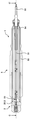
도 1은 센서 조립체와 평가 유닛을 가지는 압전 압력 센서의 제1 실시예의 단면도;
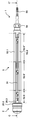
도 2는 센서 조립체와 평가 유닛을 가지는 압전 압력 센서의 제2 실시예의 단면도;
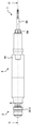
도 3은 도1 또는 2에 의한 센서 조립체의 바람직한 실시예를 보이는 단면도;
도 4는 도 1에 의한 압전 압력 센서의 제1 실시예를 평가 유닛 하우징과 전기적 절연 부재를 제거하고 보인 부분 평면도;
도 5는 도 1 또는 4에 의한 압전 압력 센서의 제1 실시예의 전기 회로기판을 보이는 측면도;
도 6은 도 1, 4 또는 5에 의한 압전 압력 센서의 제1 실시예의 전기 회로기판을 보이는 평면도;
도 7은 도 2에 의한 압전 압력 센서의 제2 실시예를 평가 유닛 하우징과 전기적 절연 부재를 제거하고 보인 부분 평면도;
도 8은 도 2 또는 7에 의한 압전 압력 센서의 제2 실시예의 전기 회로기판을 보이는 평면도;
도 9는 도 2, 7 또는 8에 의한 압전 압력 센서의 제2 실시예의 전기 회로기판을 보이는 측면도;
도 10은 도 4에 의한 압전 압력 센서의 제1 실시예의 영역 A에 대한 확대 평면도;
도 11은 도 7에 의한 압전 압력 센서의 제2 실시예의 영역 B에 대한 확대 평면도;
도 12는 전기적 절연 부재를 위에 맞춤하는 동안의 도 4에 의한 압전 압력 센서의 제1 실시예의 측면도;
도 13은 전기적 절연 부재를 맞춤한 다음의 도 4에 의한 압전 압력 센서의 제1 실시예의 측면도;
도 14는 도 12 또는 13에 따른 전기적 절연 부재의 횡단면도;
도 15는 센서 조립체의 전극 배열과 평가 유닛의 전기 회로기판 간의 재질 접합을 수행하기 전의 도 1, 4, 12 또는 13에 의한 압전 압력 센서의 제1 실시예의 평면도;
도 16은 센서 조립체의 전극 배열과 평가 유닛의 전기 회로기판 간의 재질 접합을 수행한 후의 도 1, 4, 12, 13 또는 15에 의한 압전 압력 센서의 제1 실시예의 평면도;
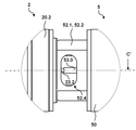
도 17은 도 15에 의한 압전 압력 센서의 제1 실시예의 영역 C에 대한 확대 평면도이다.
AA', BB', CC' 축(axis)
AB 반경 방향 평면(radial plane)
1 (압전) 압력 센서(pressure sensor)
2 센서 조립체(sensor assembly)
5 평가 유닛(evaluation unit)
20 센서 하우징 조립체(sensor housing assembly)
20.1 밀봉 콘(sealing cone)
20.2 센서 플랜지(sensor flange)
20.3 센서 하우징 프레임(sensor housing frame)
21 멤브레인(membrane)
22 센서(sensor)
22.1, 22.3 지지 부재(support element)
22.2 압전 센서 부재(piezoelectric sensor element)
23 전극 배열(electrode arrangement)
23.1 전하 픽오프(charge pick-off)
23.2 전하 출력(charge output)
25 전기적 절연 몸체(electric insulation body)
26 보상 부재(compensation element)
50 평가 유닛 하우징(evaluation unit housing)
51 전기 회로기판(electric circuit board)
51.1 고온 영역(high temperature region)
51.2 상온 영역(normal temperature region)
52.1, 52.2 보강 부재(reinforcement element)
52.3, 52.3' 잠금 부재(locking element)
52.4 창(window)
52.5 절곡 영역(bending zone)
52.6, 52.6', 52.6'' 영역(area)
53 전기적 연결 부재(electrical connection element)
53.0 (소켓 형태의) 어댑터(adapter in the form of a socket)
53.1 고리형 어댑터(annular adapter)
53.2 보상 부재(compensation element)
54 신호 케이블 플랜지(signal cable flange)
55 신호 케이블(signal cable)
Claims (15)
- 센서 조립체(2)와 평가 유닛(5)을 구비하며; 상기 센서 조립체(2)가 센서(22)와 전극 배열(23)을 구비하고; 상기 센서(22)가 압력 프로파일의 작용 하에서 신호를 생성하고; 상기 전극 배열(23)이 신호를 평가 유닛(5)으로 전송하는 압력 센서(1)에 있어서,
상기 평가 유닛(5)이 평가 유닛 하우징(50)과, 전기 회로기판(51)과, 그리고 보강 부재(52.1, 52.2)를 구비하고;
상기 보강 부재(52.1, 52.2)가 전기 회로 기판(51)과 평가 유닛 하우징(50) 사이의 반경 방향 평면(AB) 내에 배치되며;
상기 보강 부재(52.1, 52.2)가 전기 회로 기판(51)에 기계적으로 연결되고; 그리고
보강 부재(52.1, 52.2)가 반경 방향 평면(AB) 내에 발생되는 전기 회로 기판(51)의 기계적 공진 진동를 감쇠시키는 것을
특징으로 하는 압력 센서. - 제1항에 있어서,
압력 센서(1)가 압전 압력 센서(1)이고;
센서(22)가 압전 센서(22)이며;
압전 센서(22)가 압력 프로파일의 작용 하에 압전 전하를 생성하고; 그리고
전극 배열(23)이 압전 센서(22)로부터 압전 전하를 수신하여 수신된 압전 전하를 평가 유닛(5)으로 전송하는 것을
특징으로 하는 압력 센서. - 제1항 또는 제2항 중의 어느 한 항에 있어서,
보강 부재(52.1, 52.2)가 반경 방향 평면(AB)의 어떤 영역에서 전기 회로기판(51)의 둘레에 배치되고;
보강 부재(52.1, 52.2)가 전기 회로기판(51)을 라이너 또는 표면 접촉에 의해 포장하는 것을
특징으로 하는 압력 센서. - 제1항 내지 제3항 중의 어느 한 항에 있어서,
보강 부재(52.1, 52.2)가 종축(CC')을 따른 어떤 영역에서 전기 회로기판(51)을 포장하는 것을
특징으로 하는 압력 센서. - 제1항 내지 제3항 중의 어느 한 항에 있어서,
보강 부재(52.1, 52.2)가 반경 방향 평면(AB) 내에서 전기 회로기판(51)을 완전히 포장하는 것을
특징으로 하는 압력 센서. - 제1항 내지 제5항 중의 어느 한 항에 있어서,
보강 부재(52.1, 52.2)가 반경 방향 평면(AB) 내에서 전기 회로기판(51)의 이동의 자유를 평가 유닛 하우징(50)에 대해 고정하는 것을
특징으로 하는 압력 센서. - 제1항 내지 제6항 중의 어느 한 항에 있어서,
보강 부재(52.1, 52.2)가 적어도 두 동일한 쉘(52.1, 52.2)로 구성되고, 상기 쉘(52.1, 52.2)이 전기 회로기판(51)에 기계적으로 연결되거나 및/또는 서로 ㄱ기계적으로 연결될 수 있는 것을
특징으로 하는 압력 센서. - 제7항에 있어서,
쉘(52.1, 52.2)이 적어도 하나의 돌출하는 잠금 부재(52.3, 52.3')를 통해 전기 회로기판(51)에 기계적으로 연결될 수 있고;
쉘(52.1, 52.2) 중의 하나의 잠금 부재(52.3, 52.3')가 다른 쉘(52.1, 52.2)의 대응 개구부를 통해 전기 회로기판(51)에 맞물리며; 그리고
전기 회로기판(51)이 쉘(52.1, 52.2)들 사이의 반경 방향 평면(AB) 내에 배치되는 것을
특징으로 하는 압력 센서. - 제7항에 있어서,
쉘(52.1, 52.2)들이 적어도 하나의 돌출하는 잠금 부재(52.3, 52.3')를 통해 서로 기계적으로 연결되고;
쉘(52.1, 52.2) 중의 하나의 잠금 부재(52.3, 52.3')가 다른 쉘(52.1, 52.2)의 대응 개구부에 맞물리며; 그리고
전기 회로기판(51)이 쉘(52.1, 52.2)들 사이의 반경 방향 평면(AB) 내에 배치되는 것을
특징으로 하는 압력 센서. - 제1항 내지 제9항 중의 어느 한 항에 있어서,
평가 유닛(5)이 평가 유닛 하우징(50)을 구비하고; 그리고
평가 유닛 하우징(50)이 어떤 영역에서 보강 부재(52.1, 52.2)를 전기 회로기판(51) 상으로 가압하는 것을
특징으로 하는 압력 센서. - 제10항에 있어서,
보강 부재(52.1, 52.2)가 종방향으로 몇 개의 영역(52.6, 52.6', 52.6")을 구비하고;
각 영역(52.6, 52.6', 52.6")이 종방향을 따라 30mm, 바람직하기로 60mm, 더욱 바람직하기로 90mm의 길이를 가지는 것을
특징으로 하는 압력 센서. - 제10항에 있어서,
평가 유닛 하우징(50)이 종방향을 따라 후방 영역(52.6")으로부터 전방 영역(52.6)의 보강 부재(52.1, 52.2) 상으로 미끄럼 이동 가능하고;
보강 부재(52.1, 52.2)가 후방 영역(52.6")과 전방 영역(52.6)에서 다른 외경을 가지는 것을
특징으로 하는 압력 센서. - 제10항에 있어서,
평가 유닛 하우징(50)이 종방향을 따라 후방 영역(52.6")으로부터 중앙 영역(52.6')으로 중앙 영역(52.6')으로부터 전방 영역(52.6)의 보강 부재(52.1, 52.2) 상으로 미끄럼 이동 가능하고;
보강 부재(52.1, 52.2)가 후방 영역(52.6")과 중앙 영역(52.6')과 전방 영역(52.6)에서 다른 외경들을 가지며;
중앙 영역(52.6')의 외경이 평가 유닛 하우징(50)의 내경보다 약간 크고; 그리고
약간 크기가 크더라도 평가 유닛 하우징(50)이 보강 부재(52.1, 52.2) 상으로 손으로 미끄럼 이동 가능한 것을
특징으로 하는 압력 센서. - 제12항 또는 제13항 중의 어느 한 항에 있어서,
전방 영역(52.6)의 외경이 평가 유닛 하우징(50)의 내경에 비해 더 큰 크기를 가지고; 그리고
더 큰 크기를 가지면, 평가 유닛 하우징(50)을 더 이상 보강 부재(52.1, 52.2) 상으로 손으로 미끄럼 이동시킬 수 없는 것을
특징으로 하는 압력 센서. - 제1항 내지 제14항 중의 어느 한 항에 있어서,
보강 부재(52.1, 52.2)가 전기 회로기판(51), 보강 부재(52.1, 52.2) 및/또는 평가 유닛(5)의 평가 유닛 하우징(50) 간의 선형 열팽창계수의 차이를 보상하는 적어도 하나의 절곡 영역(52.5)를 구비하는 것을
특징으로 하는 압력 센서.
Applications Claiming Priority (4)
| Application Number | Priority Date | Filing Date | Title |
|---|---|---|---|
| EP15179379.1 | 2015-07-31 | ||
| EP15179379 | 2015-07-31 | ||
| EP16151559 | 2016-01-15 | ||
| EP16151559.8 | 2016-01-15 |
Publications (2)
| Publication Number | Publication Date |
|---|---|
| KR20170015257A true KR20170015257A (ko) | 2017-02-08 |
| KR102521007B1 KR102521007B1 (ko) | 2023-04-11 |
Family
ID=56292637
Family Applications (1)
| Application Number | Title | Priority Date | Filing Date |
|---|---|---|---|
| KR1020160097634A Active KR102521007B1 (ko) | 2015-07-31 | 2016-07-30 | 압력 센서와 그 제조 공정 |
Country Status (6)
| Country | Link |
|---|---|
| US (1) | US10378988B2 (ko) |
| EP (1) | EP3124938B1 (ko) |
| JP (1) | JP6782115B2 (ko) |
| KR (1) | KR102521007B1 (ko) |
| CN (1) | CN106404235B (ko) |
| DK (1) | DK3124938T3 (ko) |
Families Citing this family (7)
| Publication number | Priority date | Publication date | Assignee | Title |
|---|---|---|---|---|
| JP6196960B2 (ja) * | 2014-11-20 | 2017-09-13 | 長野計器株式会社 | 圧力センサ |
| FR3043460B1 (fr) * | 2015-11-05 | 2019-01-25 | Continental Automotive France | Embout anti-resonnance de cavitation et anti-suie pour capteur de pression d'un moteur a combustion interne |
| EP3421961B1 (en) * | 2016-02-25 | 2022-07-27 | Citizen Finedevice Co., Ltd. | Pressure detection device and pressure detection system |
| JP7107232B2 (ja) * | 2019-01-09 | 2022-07-27 | 株式会社ジェイテクト | センサ |
| US11156511B2 (en) * | 2019-04-09 | 2021-10-26 | Honeywell International Inc. | Load cell |
| ES2886581A1 (es) * | 2020-06-17 | 2021-12-20 | Cebi Electromechanical Components Spain S A | Dispositivo de medicion de presion y temperatura |
| CN115112275B (zh) * | 2022-06-23 | 2024-06-14 | 中国科学院力学研究所 | 一种可主动驱动变形的薄膜式柔性压力传感器 |
Citations (5)
| Publication number | Priority date | Publication date | Assignee | Title |
|---|---|---|---|---|
| DE3423711A1 (de) * | 1983-07-07 | 1985-01-17 | AVL Gesellschaft für Verbrennungskraftmaschinen und Messtechnik mbH, Prof. Dr.Dr.h.c. Hans List, Graz | Messwertaufnehmer zur messung heisser medien, sowie verfahren zu seiner montage |
| US4645965A (en) * | 1984-10-26 | 1987-02-24 | Texas Instruments Incorporated | Cylinder pressure transmitter for an internal combustion engine |
| JP2014048045A (ja) * | 2012-08-29 | 2014-03-17 | Citizen Finetech Miyota Co Ltd | 燃焼圧センサ |
| KR20140115268A (ko) * | 2013-03-20 | 2014-09-30 | 센사타 테크놀로지스, 인크 | 측정 플러그 및 측정 플러그를 조립하는 방법 |
| JP2015121426A (ja) * | 2013-12-20 | 2015-07-02 | 株式会社デンソー | 溶接部を有する継手構造の組付構造 |
Family Cites Families (18)
| Publication number | Priority date | Publication date | Assignee | Title |
|---|---|---|---|---|
| CH394637A (de) | 1963-04-05 | 1965-06-30 | Kistler Instrumente Ag | Verfahren zur Herstellung eines piezoelektrischen Messwandlers |
| US3364368A (en) | 1963-04-05 | 1968-01-16 | Messrs Kistler Instr A G | Piezo-electric transducer |
| GB2022261A (en) | 1978-04-28 | 1979-12-12 | Atomic Energy Authority Uk | A piezo-electric pressure transducer |
| DE3376760D1 (en) | 1983-11-10 | 1988-06-30 | Kristal Instr Ag | Transducer element, method for its manufacture and its use in a pressure pick-up device |
| DE3584070D1 (de) * | 1984-10-26 | 1991-10-17 | Texas Instruments Inc | Zylinderdruckwandler fuer eine verbrennungskraftmaschine. |
| US4701726A (en) * | 1985-12-03 | 1987-10-20 | Northeast Filter Co., Inc. | Trap filter assembly |
| US4765659A (en) * | 1986-07-28 | 1988-08-23 | General Motors Corporation | High pressure tube attachment mechanism |
| DE4314296A1 (de) * | 1993-04-30 | 1994-11-03 | Hydac Electronic Gmbh | Sensoreinheit mit Haltebügel |
| TW382180B (en) * | 1996-07-15 | 2000-02-11 | Sony Corp | Camera lens |
| JPH1032035A (ja) * | 1996-07-15 | 1998-02-03 | Sony Corp | 丸形コネクタ及び可撓性プリント配線基板の接続装置 |
| JPH1144599A (ja) * | 1997-07-29 | 1999-02-16 | Tec Corp | 圧力センサユニット |
| US20030076691A1 (en) * | 2001-10-19 | 2003-04-24 | Becks Eric Roger | Impact resistant - long life trouble light |
| DE102004007202B4 (de) * | 2003-02-17 | 2016-06-16 | Denso Corporation | Druckdetektor mit langgestrecktem Gehäuse zur Aufnahme eines druckempfindlichen Elementes |
| JP4742593B2 (ja) | 2005-01-19 | 2011-08-10 | 株式会社デンソー | 圧力検出装置の製造方法 |
| DE102012204905B4 (de) * | 2012-03-27 | 2024-07-11 | Robert Bosch Gmbh | Schaltungsträger für eine Sensoreinheit und korrespondierende Sensoreinheit |
| WO2013147260A1 (ja) | 2012-03-29 | 2013-10-03 | シチズンファインテックミヨタ株式会社 | 圧力検出装置、圧力検出装置付き内燃機関 |
| JP5820759B2 (ja) * | 2012-03-29 | 2015-11-24 | シチズンファインデバイス株式会社 | 圧力検出装置の製造方法、圧力検出装置付き内燃機関の製造方法 |
| EP2808665B1 (en) * | 2013-05-28 | 2019-02-20 | Sensata Technologies, Inc. | A measuring plug |
-
2016
- 2016-07-07 EP EP16178293.3A patent/EP3124938B1/de active Active
- 2016-07-07 DK DK16178293.3T patent/DK3124938T3/da active
- 2016-07-27 US US15/221,243 patent/US10378988B2/en active Active
- 2016-07-29 JP JP2016149764A patent/JP6782115B2/ja active Active
- 2016-07-30 KR KR1020160097634A patent/KR102521007B1/ko active Active
- 2016-08-01 CN CN201610620983.8A patent/CN106404235B/zh active Active
Patent Citations (5)
| Publication number | Priority date | Publication date | Assignee | Title |
|---|---|---|---|---|
| DE3423711A1 (de) * | 1983-07-07 | 1985-01-17 | AVL Gesellschaft für Verbrennungskraftmaschinen und Messtechnik mbH, Prof. Dr.Dr.h.c. Hans List, Graz | Messwertaufnehmer zur messung heisser medien, sowie verfahren zu seiner montage |
| US4645965A (en) * | 1984-10-26 | 1987-02-24 | Texas Instruments Incorporated | Cylinder pressure transmitter for an internal combustion engine |
| JP2014048045A (ja) * | 2012-08-29 | 2014-03-17 | Citizen Finetech Miyota Co Ltd | 燃焼圧センサ |
| KR20140115268A (ko) * | 2013-03-20 | 2014-09-30 | 센사타 테크놀로지스, 인크 | 측정 플러그 및 측정 플러그를 조립하는 방법 |
| JP2015121426A (ja) * | 2013-12-20 | 2015-07-02 | 株式会社デンソー | 溶接部を有する継手構造の組付構造 |
Also Published As
| Publication number | Publication date |
|---|---|
| JP6782115B2 (ja) | 2020-11-11 |
| CN106404235A (zh) | 2017-02-15 |
| CN106404235B (zh) | 2020-08-07 |
| KR102521007B1 (ko) | 2023-04-11 |
| US10378988B2 (en) | 2019-08-13 |
| EP3124938A1 (de) | 2017-02-01 |
| JP2017032562A (ja) | 2017-02-09 |
| EP3124938B1 (de) | 2019-02-20 |
| US20170030793A1 (en) | 2017-02-02 |
| DK3124938T3 (da) | 2019-05-13 |
Similar Documents
| Publication | Publication Date | Title |
|---|---|---|
| KR102507131B1 (ko) | 압력 센서 | |
| KR102521003B1 (ko) | 압력 센서와 그 제조 공정 | |
| KR102521007B1 (ko) | 압력 센서와 그 제조 공정 | |
| KR102521006B1 (ko) | 압전 압력 센서 | |
| JP4928559B2 (ja) | シース型グロープラグ | |
| KR102521004B1 (ko) | 압전 압력 센서 | |
| JP6764770B2 (ja) | 圧力検出装置および圧力検出装置付き内燃機関 | |
| JP7713353B2 (ja) | 圧力検出装置 | |
| JP2025152240A (ja) | 圧力検出装置、圧電モジュール、圧電モジュールの製造方法 | |
| JP2017181191A (ja) | 圧力検出装置および圧電素子 |
Legal Events
| Date | Code | Title | Description |
|---|---|---|---|
| PA0109 | Patent application |
Patent event code: PA01091R01D Comment text: Patent Application Patent event date: 20160730 |
|
| PG1501 | Laying open of application | ||
| A201 | Request for examination | ||
| PA0201 | Request for examination |
Patent event code: PA02012R01D Patent event date: 20210730 Comment text: Request for Examination of Application Patent event code: PA02011R01I Patent event date: 20160730 Comment text: Patent Application |
|
| E902 | Notification of reason for refusal | ||
| PE0902 | Notice of grounds for rejection |
Comment text: Notification of reason for refusal Patent event date: 20221014 Patent event code: PE09021S01D |
|
| E701 | Decision to grant or registration of patent right | ||
| PE0701 | Decision of registration |
Patent event code: PE07011S01D Comment text: Decision to Grant Registration Patent event date: 20230324 |
|
| GRNT | Written decision to grant | ||
| PR0701 | Registration of establishment |
Comment text: Registration of Establishment Patent event date: 20230407 Patent event code: PR07011E01D |
|
| PR1002 | Payment of registration fee |
Payment date: 20230407 End annual number: 3 Start annual number: 1 |
|
| PG1601 | Publication of registration |