KR20170051908A - petri dish - Google Patents
petri dish Download PDFInfo
- Publication number
- KR20170051908A KR20170051908A KR1020150153588A KR20150153588A KR20170051908A KR 20170051908 A KR20170051908 A KR 20170051908A KR 1020150153588 A KR1020150153588 A KR 1020150153588A KR 20150153588 A KR20150153588 A KR 20150153588A KR 20170051908 A KR20170051908 A KR 20170051908A
- Authority
- KR
- South Korea
- Prior art keywords
- container body
- cover
- protrusion
- fitting
- insertion groove
- Prior art date
- Legal status (The legal status is an assumption and is not a legal conclusion. Google has not performed a legal analysis and makes no representation as to the accuracy of the status listed.)
- Withdrawn
Links
- 238000003780 insertion Methods 0.000 claims description 64
- 230000037431 insertion Effects 0.000 claims description 64
- 238000000034 method Methods 0.000 claims description 13
- 230000000284 resting effect Effects 0.000 claims 1
- 244000005700 microbiome Species 0.000 description 3
- 238000012258 culturing Methods 0.000 description 2
- 239000002609 medium Substances 0.000 description 2
- 238000011109 contamination Methods 0.000 description 1
- 239000001963 growth medium Substances 0.000 description 1
- 238000012986 modification Methods 0.000 description 1
- 230000004048 modification Effects 0.000 description 1
Images







Classifications
-
- C—CHEMISTRY; METALLURGY
- C12—BIOCHEMISTRY; BEER; SPIRITS; WINE; VINEGAR; MICROBIOLOGY; ENZYMOLOGY; MUTATION OR GENETIC ENGINEERING
- C12M—APPARATUS FOR ENZYMOLOGY OR MICROBIOLOGY; APPARATUS FOR CULTURING MICROORGANISMS FOR PRODUCING BIOMASS, FOR GROWING CELLS OR FOR OBTAINING FERMENTATION OR METABOLIC PRODUCTS, i.e. BIOREACTORS OR FERMENTERS
- C12M3/00—Tissue, human, animal or plant cell, or virus culture apparatus
-
- B—PERFORMING OPERATIONS; TRANSPORTING
- B01—PHYSICAL OR CHEMICAL PROCESSES OR APPARATUS IN GENERAL
- B01L—CHEMICAL OR PHYSICAL LABORATORY APPARATUS FOR GENERAL USE
- B01L3/00—Containers or dishes for laboratory use, e.g. laboratory glassware; Droppers
-
- C—CHEMISTRY; METALLURGY
- C12—BIOCHEMISTRY; BEER; SPIRITS; WINE; VINEGAR; MICROBIOLOGY; ENZYMOLOGY; MUTATION OR GENETIC ENGINEERING
- C12M—APPARATUS FOR ENZYMOLOGY OR MICROBIOLOGY; APPARATUS FOR CULTURING MICROORGANISMS FOR PRODUCING BIOMASS, FOR GROWING CELLS OR FOR OBTAINING FERMENTATION OR METABOLIC PRODUCTS, i.e. BIOREACTORS OR FERMENTERS
- C12M23/00—Constructional details, e.g. recesses, hinges
- C12M23/02—Form or structure of the vessel
- C12M23/10—Petri dish
-
- C—CHEMISTRY; METALLURGY
- C12—BIOCHEMISTRY; BEER; SPIRITS; WINE; VINEGAR; MICROBIOLOGY; ENZYMOLOGY; MUTATION OR GENETIC ENGINEERING
- C12M—APPARATUS FOR ENZYMOLOGY OR MICROBIOLOGY; APPARATUS FOR CULTURING MICROORGANISMS FOR PRODUCING BIOMASS, FOR GROWING CELLS OR FOR OBTAINING FERMENTATION OR METABOLIC PRODUCTS, i.e. BIOREACTORS OR FERMENTERS
- C12M29/00—Means for introduction, extraction or recirculation of materials, e.g. pumps
- C12M29/26—Conditioning fluids entering or exiting the reaction vessel
Landscapes
- Health & Medical Sciences (AREA)
- Life Sciences & Earth Sciences (AREA)
- Engineering & Computer Science (AREA)
- Chemical & Material Sciences (AREA)
- Wood Science & Technology (AREA)
- Organic Chemistry (AREA)
- Bioinformatics & Cheminformatics (AREA)
- Zoology (AREA)
- Biomedical Technology (AREA)
- General Health & Medical Sciences (AREA)
- Sustainable Development (AREA)
- Microbiology (AREA)
- Biotechnology (AREA)
- Biochemistry (AREA)
- General Engineering & Computer Science (AREA)
- Genetics & Genomics (AREA)
- Clinical Laboratory Science (AREA)
- Virology (AREA)
- Cell Biology (AREA)
- Chemical Kinetics & Catalysis (AREA)
- Apparatus Associated With Microorganisms And Enzymes (AREA)
Abstract
본 발명은 용기본체에 커버를 보다 용이하게 결합시킬 수 있음은 물론 상기 용기본체로부터 상기 커버를 많은 힘을 들이지 않고도 간편하게 분리시킬 수 있고, 나아가, 상기 용기본체의 상부와 상기 커버의 상부 사이에 형성되는 공기유입공간의 상하폭을 조절할 수 있으며, 아울러, 상기 커버의 내측면 상부에 형성되는 지지리브를 통해 상기 공기유입공간이 완전폐쇄되는 것을 방지할 수 있는 페트리디쉬에 관한 것이다.The present invention is not only capable of easily connecting the cover to the container body, but also can easily separate the cover from the container body without much force, and further, is formed between the top of the container body and the top of the cover And to prevent the air inflow space from being completely closed through a support rib formed on the inner side surface of the cover.
Description
본 발명은 용기본체에 커버를 보다 용이하게 결합시킬 수 있음은 물론 상기 용기본체로부터 상기 커버를 많은 힘을 들이지 않고도 간편하게 분리시킬 수 있고, 나아가, 상기 용기본체의 상부와 상기 커버의 상부 사이에 형성되는 공기유입공간의 상하폭을 조절할 수 있으며, 아울러, 상기 커버의 내측면 상부에 형성되는 지지리브를 통해 상기 공기유입공간이 완전폐쇄되는 것을 방지할 수 있는 페트리디쉬에 관한 것이다.The present invention is not only capable of easily connecting the cover to the container body, but also can easily separate the cover from the container body without much force, and further, is formed between the top of the container body and the top of the cover And to prevent the air inflow space from being completely closed through a support rib formed on the inner side surface of the cover.
일반적으로, 미생물 또는 식물 조직이나 식물 등을 배양할 때 사용되는 페트리디쉬는 상부가 개방되어 내부에 배지를 담을 수 있도록 된 용기 본체와; 이 용기 본체에 결합되어 배지가 미생물 등에 의해 오염되는 것을 방지하는 커버;로 구성되어, 용기 본체에 배양할 미생물 또는 식물의 조직이나 식물 등을 넣고 커버를 닫아 배양시킬 수 있다.2. Description of the Related Art Generally, a petri dish used for culturing a microorganism or a plant tissue or a plant has a container body which is opened at an upper part and is capable of containing a medium therein; And a cover coupled to the container body to prevent contamination of the culture medium with microorganisms and the like. The microorganism or plant tissue or plant to be cultivated can be put into the container body and the cover can be closed and cultured.
이러한 페트리디쉬는 상기 커버는 대부분 상기 용기 본체의 상부에 나사결합되는 방식으로서, 상기 커버를 상기 용기 본체에 간편하게 결합시킬 수는 있겠으나, 상기 용기 본체에 결합된 상기 커버를 분리하기가 쉽지 않음은 물론 상기 용기 본체로부터 상기 커버를 분리하는데 많은 힘을 요구하는 문제점이 있다.Such a petri dish can be easily coupled to the container body in a manner that the cover is mostly screwed to the top of the container body, but it is not easy to separate the cover coupled to the container body. Of course, there is a problem that much force is required to separate the cover from the container body.
본 발명은 상술한 문제점을 해결하기 위하여 창출된 것으로서, 용기본체의 삽입홈에 커버의 삽입돌기를 삽입 또는 용기본체의 삽입돌기가 커버의 삽입홈내에 삽입하여 상기 용기본체에 상기 커버를 보다 용이하게 결합시킬 수 있음은 물론 상기 용기본체로부터 상기 커버를 많은 힘을 들이지 않고도 간편하게 분리시킬 수 있고, 나아가 상기 용기본체의 상부와 상기 커버의 상부 사이에 형성되는 공기유입공간의 상하폭을 조절하여 상기 용기본체내로 유입되는 배양체가 필요로 하는 공기양을 보다 용이하게 조절할 수 있고, 아울러, 상기 커버의 내측면 상부에 형성되는 지지리브를 통해 상기 공기유입공간이 완전폐쇄되는 것을 보다 용이하게 방지할 수 있는 페트리디쉬를 제공하는 것을 그 목적으로 한다.SUMMARY OF THE INVENTION The present invention has been made in order to solve the above problems, and it is an object of the present invention to provide a container body which can easily insert the insertion protrusion of the cover into the insertion groove of the container body or insert the insertion protrusion of the container body into the insertion groove of the cover, And the upper and lower widths of the air inflow space formed between the upper part of the container body and the upper part of the cover can be adjusted so that the container can be easily separated from the container body, It is possible to more easily adjust the amount of air required by the culture body introduced into the main body and to more easily prevent the air inflow space from being completely closed through the support ribs formed on the inner side surface of the cover The purpose is to provide a petri dish.
상기와 같은 목적을 달성하기 위한 본 발명은 외측면에 삽입홈이 등간격으로 형성되는 용기본체와; 상기 용기본체에 결합되도록 내측면에 상기 용기본체의 외측면 방향으로 돌출되어 상기 삽입홈내에 삽입되는 삽입돌기가 등간격으로 형성되는 커버;를 포함하여 이루어지는 것을 특징으로 하는 페트리디쉬를 제공한다.According to an aspect of the present invention, there is provided a container comprising: a container body having an insertion groove formed at an equal interval on an outer surface thereof; And a cover which protrudes in the direction of the outer surface of the container body on the inner side so as to be coupled to the container body and has insertion protrusions formed at equal intervals to be inserted into the insertion groove.
또한, 본 발명은 외측면에 삽입돌기가 등간격으로 형성되는 용기본체와; 상기 용기본체에 결합되도록 내측면에 상기 용기본체의 삽입돌기가 삽입되는 삽입홈이 등간격으로 형성되는 커버;를 포함하여 이루어지는 것을 특징으로 하는 페트리디쉬를 제공한다.According to another aspect of the present invention, there is provided a container comprising: a container body having insertion protrusions formed at regular intervals on an outer surface thereof; And a cover on which an insertion protrusion for inserting the insertion protrusion of the container body is formed at an equal interval so as to be coupled to the container body.
여기서, 상기 용기본체의 외측면에 상기 삽입홈을 형성하기 위한 돌출부재가 상기 용기본체의 외측방향으로 돌출형성되고, 상기 돌출부재의 내측에 상기 삽입홈이 상기 돌출부재의 일측에서 타측방향으로 일정길이로 좌우연장형성되는 것이 바람직하다.A protrusion member for forming the insertion groove is formed on an outer surface of the container body so as to protrude outwardly of the container body. The insertion groove is formed on the inner side of the protrusion member, As shown in Fig.
그리고, 상기 커버의 내측면에 상기 삽입홈을 형성하기 위한 돌출부재가 상기 커버의 내측방향으로 돌출형성되고, 상기 돌출부재의 내측에 상기 삽입홈이 상기 돌출부재의 일측에서 타측방향으로 일정길이로 좌우연장형성되는 것이 바람직하다.A protrusion member for forming the insertion groove is formed on the inner side surface of the cover so as to protrude inward of the cover, and the insertion groove is formed on the inner side of the protrusion member, It is preferably extended.
더욱이, 상기 용기본체의 외측면에 형성된 상기 돌출부재는 상기 돌출부재의 일측에서 타측방향으로 갈수록 하향경사지고, 상기 커버의 내측면에 형성된 상기 삽입돌기는 상기 돌출부재를 따라 하향경사지는 것이 바람직하다.Further, it is preferable that the protruding member formed on the outer surface of the container body is inclined downward from one side of the protruding member toward the other side, and the insertion protrusion formed on the inner surface of the cover is inclined downward along the protruding member .
그리고, 상기 커버의 내측면에 형성된 상기 돌출부재는 상기 돌출부재의 일측에서 타측방향으로 갈수록 하향경사지고, 상기 용기본체의 외측면에 형성된 상기 삽입돌기는 상기 돌출부재를 따라 하향경사지는 것이 바람직하다.The protrusion member formed on the inner surface of the cover may be inclined downward from one side of the protrusion member toward the other side and the insertion protrusion formed on the outer side surface of the container body may be inclined downward along the protrusion member .
나아가, 상기 돌출부재의 내측면에 상기 삽입홈과 연통되는 끼움홈이 일정간격으로 복수형성되고, 상기 삽입돌기의 외측면에 상기 끼움홈방향으로 돌출되어 상기 끼움홈내에 끼움고정되는 끼움돌기가 일정간격으로 복수형성되는 것이 바람직하다.Further, a plurality of fitting grooves communicating with the insertion grooves are formed on the inner surface of the protruding member at a predetermined interval, and the fitting protrusions, which protrude in the fitting groove direction and are fitted and fixed in the fitting groove, It is preferable that a plurality is formed at intervals.
또는, 상기 돌출부재의 내측면에 상기 돌출부재의 내측으로 돌출되는 끼움돌기가 일정간격으로 복수형성되고, 상기 삽입돌기의 외측면에 상기 끼움돌기가 끼움고정되는 끼움홈이 일정간격으로 복수형성되는 것이 바람직하다.Alternatively, a plurality of fitting protrusions protruding inwardly of the protruding member may be formed on the inner surface of the protruding member at a predetermined interval, and a plurality of fitting grooves, into which the fitting protrusions are fitted, .
아울러, 상기 커버의 내측면 상부에 지지리브가 등간격으로 형성되고, 상기 지지리브는 상기 용기본체의 외측면과 상기 커버의 내측면 사이에 수직구비되는 수직지지리브와; 상기 수직지지리브의 상부에서 상기 커버의 내측방향으로 일정길이로 연장된 상태로 상기 용기본체의 상부에 수평안착되는 수평지지리브;를 포함하여 이루어지는 것이 바람직하다.In addition, a support rib is formed at an equal interval above the inner surface of the cover, and the support rib is vertically provided between the outer surface of the container body and the inner surface of the cover; And a horizontal support rib horizontally mounted on the upper portion of the container main body in a state of extending from the upper portion of the vertical support rib to a predetermined length in the inner direction of the cover.
본 발명은 용기본체의 삽입홈에 커버의 삽입돌기를 삽입 또는 용기본체의 삽입돌기가 커버의 삽입홈내에 삽입하여 상기 용기본체에 상기 커버를 보다 용이하게 결합시킬 수 있음은 물론 상기 용기본체로부터 상기 커버를 많은 힘을 들이지 않고도 간편하게 분리시킬 수 있고, 나아가 상기 용기본체의 상부와 상기 커버의 상부 사이에 형성되는 공기유입공간의 상하폭을 조절하여 상기 용기본체내로 유입되는 배양체가 필요로 하는 공기양을 보다 용이하게 조절할 수 있고, 아울러, 상기 커버의 내측면 상부에 형성되는 지지리브를 통해 상기 공기유입공간이 완전폐쇄되는 것을 보다 용이하게 방지할 수 있는 효과가 있다.The present invention can insert the insertion protrusion of the cover into the insertion groove of the container body or insert the insertion protrusion of the container body into the insertion groove of the cover to easily attach the cover to the container body, The upper and lower widths of the air inflow space formed between the upper portion of the container body and the upper portion of the cover are adjusted so that the amount of air required by the culture body flowing into the container body And it is also possible to more easily prevent the air inflow space from being completely closed through the support ribs formed on the inner side surface of the cover.
도 1은 본 발명의 일실시예인 페트리디쉬를 개략적으로 나타내는 사시도이고,
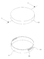
도 2는 도 1의 분리사시도이고,
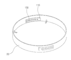
도 3은 일실시예의 커버의 내측면에 삽입돌기가 형성된 상태를 개략적으로 나타내는 사시도이고,
도 4 및 도 5는 일실시예의 용기본체와 커버가 결합되는 과정을 개략적으로 나타내는 정면도이고,
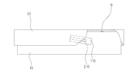
도 6 및 도 7은 일실시예의 용기본체의 상부와 커버의 상부 사이에 형성되는 공기유입공간의 상하폭이 조절되는 과정을 개략적으로 나타내는 정면도이고,
도 8은 끼움홈과 끼움돌기의 일예를 개략적으로 나타내는 일부확대정면도이고,
도 9는 끼움홈과 끼움돌기의 다른예를 개략적으로 나타내는 일부확대정면도이고,
도 10은 본 발명의 다른 실시예인 페트리디쉬를 개략적으로 나타내는 분리사시도이고,
도 11은 다른 실시예의 커버의 내측면에 삽입홈이 형성된 상태를 개략적으로 나타내는 사시도이고,
도 12 및 도 13은 다른 실시예의 용기본체와 커버가 결합되는 과정을 개략적으로 나타내는 정면도이고,
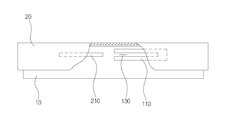
도 14는 도 2의 B - B선에 따른 단면도이고,
도 15는 도 1의 A - A선에 따른 단면도이다.1 is a perspective view schematically showing a petri dish according to an embodiment of the present invention,
Fig. 2 is an exploded perspective view of Fig. 1,
3 is a perspective view schematically showing a state in which an insertion protrusion is formed on an inner surface of a cover according to an embodiment,
4 and 5 are front views schematically showing a process of joining the container body and the cover of one embodiment,
6 and 7 are front views schematically illustrating a process of adjusting the vertical width of the air inflow space formed between the upper part of the container body and the upper part of the cover of the embodiment,
8 is a partially enlarged front view schematically showing an example of a fitting groove and a fitting projection,
9 is a partially enlarged front view schematically showing another example of the fitting groove and the fitting projection,
10 is an exploded perspective view schematically showing a petri dish, which is another embodiment of the present invention,
11 is a perspective view schematically showing a state in which an insertion groove is formed in an inner side surface of a cover according to another embodiment,
12 and 13 are front views schematically showing a process of joining the container body and the cover of another embodiment,
Fig. 14 is a sectional view taken along the line B-B in Fig. 2,
15 is a cross-sectional view taken along the line A-A in Fig.
이하, 본 발명의 바람직한 실시예를 첨부한 도면에 의거하여 보다 상세하게 설명하면 다음과 같다. 물론 본 발명의 권리범위는 하기의 실시예에 한정되는 것은 아니며, 본 발명의 기술적 요지를 벗어나지 않는 범위 내에서 당해 기술분야의 통상적인 지식을 가진자에 의하여 다양하게 변형 실시될 수 있다.Hereinafter, preferred embodiments of the present invention will be described in more detail with reference to the accompanying drawings. It is to be understood that the scope of the present invention is not limited to the following embodiments, and various modifications may be made by those skilled in the art without departing from the technical scope of the present invention.
도 1은 본 발명의 일실시예인 페트리디쉬를 개략적으로 나타내는 사시도이고, 도 2는 도 1의 분리사시도이고, 도 3은 일실시예의 커버의 내측면에 삽입돌기가 형성된 상태를 개략적으로 나타내는 사시도이다.FIG. 1 is a perspective view schematically showing a petri dish according to an embodiment of the present invention, FIG. 2 is an exploded perspective view of FIG. 1, and FIG. 3 is a perspective view schematically showing an insertion protrusion formed on an inner surface of a cover of an embodiment .
본 발명의 일실시예인 페트리디쉬는 도 1 내지 도 3에서 보는 바와 같이 크게 용기본체(10)와 커버(20)를 포함하여 이루어진다.As shown in FIGS. 1 to 3, the petri dish, which is one embodiment of the present invention, includes a
먼저, 도 1에서 보는 바와 같이 상기 용기본체(10)의 상부는 개방되어 형성되며, 상기 용기본체(10)의 내부에는 배지를 담을 수 있다.First, as shown in FIG. 1, the upper part of the
상기 용기본체(10)의 외측면에는 도 2에서 보는 바와 같은 삽입홈(130)이 등간격으로 형성된다.On the outer surface of the
그리고, 상기 용기본체(10)의 외측면에는 도 2에서 보는 바와 같이 상기 삽입홈(130)을 형성하기 위한 돌출부재(110)가 상기 용기본체(10)의 외측방향으로 돌출형성될 수 있다.As shown in FIG. 2, a protruding
상기 삽입홈(130)은 상기 돌출부재(110)의 내측에 상기 돌출부재(110)의 일측에서 타측방향으로 일정길이로 좌우연장형성될 수 있다.The
상기 커버(20)는 도 1 및 도 2에서 보는 바와 같이 상기 용기본체(10)에 결합된다.The
이를 위해, 도 3에서 보는 바와 같이 상기 커버(20)의 내측면에는 상기 용기본체(10)의 외측면 방향으로 돌출되어 상기 삽입홈(130)내에 삽입되는 삽입돌기(210)가 등간격으로 형성된다.3,
도 4 및 도 5는 일실시예의 용기본체와 커버가 결합되는 과정을 개략적으로 나타내는 정면도이다.4 and 5 are front views schematically showing a process of joining the container body and the cover of one embodiment.
다음으로, 도 4에서 보는 바와 같이 상기 커버(20)에 형성된 삽입돌기(210)는 도 5에서 보는 바와 같이 상기 용기본체(10)에 형성된 돌출부재(110)의 삽입홈(130) 내에 삽입되어 상기 용기본체(10)에 상기 커버(20)를 보다 용이하게 결합시킬 수 있다.4, the
따라서, 상기 용기본체(10)에 상기 커버(20)를 보다 용이하게 결합시킬 수 있음은 물론 상기 용기본체(10)로부터 상기 커버(20)를 많은 힘을 들이지 않고도 간편하게 분리시킬 수 있는 이점이 있다.Therefore, the
도 6 및 도 7은 일실시예의 용기본체의 상부와 커버의 상부 사이에 형성되는 공기유입공간의 상하폭이 조절되는 과정을 개략적으로 나타내는 정면도이다.FIGS. 6 and 7 are front views schematically illustrating a process of adjusting the vertical width of the air inflow space formed between the upper part of the container body and the upper part of the cover of the embodiment.
다음으로, 상기 용기본체(10)의 상부와 상기 커버(20)의 상부 사이에 형성되는 공기유입공간(9)의 상하폭을 조절하여 상기 용기본체(10)내로 유입되는 배양체가 필요로 하는 공기양을 보다 용이하게 조절할 수 있도록 하기 위하여 도 6 및 도 7에서 보는 바와 같이 상기 용기본체(10)의 외측면에 형성된 상기 돌출부재(110)는 상기 돌출부재(110)의 일측에서 타측방향으로 갈수록 하향경사질 수 있다.Next, the upper and lower widths of the
그리고, 상기 커버(20)의 내측면에 형성된 상기 삽입돌기(210)는 상기 돌출부재(110)를 따라 하향경사질 수 있다.The
도 8은 끼움홈과 끼움돌기의 일예를 개략적으로 나타내는 일부확대정면도이고, 도 9는 끼움홈과 끼움돌기의 다른예를 개략적으로 나타내는 일부확대정면도이다.Fig. 8 is a partially enlarged front view schematically showing an example of a fitting groove and a fitting projection; and Fig. 9 is a partially enlarged front view schematically showing another example of a fitting groove and a fitting projection.
다음으로, 상기 용기본체(10)에 상기 커버(20)가 너무 쉽게 분리되는 것을 방지할 수 있도록 하기 위하여 도 8에서 보는 바와 같이 상기 돌출부재(110)의 내측면에 상기 삽입홈(130)과 연통되는 끼움홈(3)이 일정간격으로 복수형성될 수 있다.8, in order to prevent the
그리고, 상기 삽입돌기(210)의 외측면에 상기 끼움홈(3)방향으로 돌출되어 상기 끼움홈(3)내에 끼움고정되는 끼움돌기(6)가 일정간격으로 복수형성될 수 있다.A plurality of
또는, 도 9에서 보는 바와 같이 상기 돌출부재(110)의 내측면에 상기 돌출부재(110)의 내측으로 돌출되는 끼움돌기(6)가 일정간격으로 복수형성될 수 있다.Alternatively, as shown in FIG. 9, a plurality of
그리고, 상기 삽입돌기(210)의 외측면에 상기 끼움돌기(6)가 끼움고정되는 끼움홈(3)이 일정간격으로 복수형성될 수 있다.A plurality of
도 10은 본 발명의 다른 실시예인 페트리디쉬를 개략적으로 나타내는 분리사시도이다.10 is an exploded perspective view schematically showing a petri dish according to another embodiment of the present invention.
다음으로, 본 발명의 다른실시예인 페트리디쉬로서, 도 10에서 보는 바와 같이 크게 용기본체(10)와 커버(20)를 포함하여 이루어진다.Next, a petri dish, which is another embodiment of the present invention, includes a
보다 구체적으로, 도 10에서 보는 바와 같이 상기 용기본체(10)의 외측면에는 삽입돌기(210)가 등간격으로 형성된다.More specifically, as shown in FIG. 10,
상기 커버(20)는 상기 용기본체(10)에 결합된다,The
도 11은 다른 실시예의 커버의 내측면에 삽입홈이 형성된 상태를 개략적으로 나타내는 사시도이다.11 is a perspective view schematically showing a state in which an insertion groove is formed in an inner side surface of a cover according to another embodiment.
다음으로, 도 11에서 보는 바와 같이 상기 커버(20)의 내측면에는 상기 용기본체(10)의 삽입돌기(210)가 삽입되는 삽입홈(130)이 등간격으로 형성된다.11,
그리고, 상기 커버(20)의 내측면에는 상기 삽입홈(130)을 형성하기 위한 돌출부재(110)가 상기 커버(20)의 내측방향으로 돌출형성될 수 있다.A protruding
상기 돌출부재(110)의 내측에 상기 삽입홈(130)이 상기 돌출부재(110)의 일측에서 타측방향으로 일정길이로 좌우연장형성될 수 있다.The
도 12 및 도 13은 다른 실시예의 용기본체와 커버가 결합되는 과정을 개략적으로 나타내는 정면도이다.12 and 13 are front views schematically showing a process of joining the container body and the cover of another embodiment.
다음으로, 도 12에서 보는 바와 같이 상기 용기본체(10)의 외측면에 형성된 상기 삽입돌기(210)는 도 13에서 보는 바와 같이 상기 커버(20)에 형성된 돌출부재(110)의 삽입홈(130) 내에 삽입되어 상기 용기본체(10)에 상기 커버(20)를 보다 용이하게 결합시킬 수 있다.12, the
또한, 도면에는 도시하지 않았으나, 본 발명의 일실시예와 동일하게 상기 용기본체(10)의 상부와 상기 커버(20)의 상부 사이에 형성되는 공기유입공간(9)의 상하폭을 조절하여 상기 용기본체(10)내로 유입되는 배양체가 필요로 하는 공기양을 보다 용이하게 조절할 수 있도록 하기 위하여 상기 커버(20)의 내측면에 형성된 상기 돌출부재(110)는 상기 돌출부재(110)의 일측에서 타측방향으로 갈수록 하향경사질 수 있다.The upper and lower widths of the
그리고, 상기 용기본체(10)의 외측면에 형성된 상기 삽입돌기(210)는 상기 돌출부재(110)를 따라 하향경사질 수 있다.The
도 14는 도 2의 B - B선에 따른 단면도이고, 도 15는 도 1의 A - A선에 따른 단면도이다.Fig. 14 is a sectional view taken along the line B-B in Fig. 2, and Fig. 15 is a sectional view taken along line A-A in Fig.
다음으로, 상기 공기유입공간(9)이 완전폐쇄되는 것을 보다 용이하게 방지할 수 있도록 하기 위해 도 3, 도 14 및 도 15에서 보는 바와 같이 상기 커버(20)의 내측면 상부에는 지지리브(30)가 등간격으로 형성될 수 있다.3, 14 and 15, in order to more easily prevent the
상기 지지리브(30)는 수직지지리브(310) 및 수평지지리브(330)로 구성될 수 있다.The
상기 수직지지리브(310)는 상기 용기본체(10)의 외측면과 상기 커버(20)의 내측면 사이에 수직구비될 수 있다.The
상기 수평지지리브(330)는 상기 수직지지리브(310)의 상부에서 상기 커버(20)의 내측방향으로 일정길이로 연장된 상태로 상기 용기본체(10)의 상부에 수평안착될 수 있다.The
상술한 바와 같이 구성된 본 발명은 상기 용기본체(10)의 삽입홈(130)에 상기 커버(20)의 삽입돌기(210)를 삽입 또는 상기 용기본체(10)의 삽입돌기(210)가 상기 커버(20)의 삽입홈(130)내에 삽입하여 상기 용기본체(10)에 상기 커버(20)를 보다 용이하게 결합시킬 수 있음은 물론 상기 용기본체(10)로부터 상기 커버(20)를 많은 힘을 들이지 않고도 간편하게 분리시킬 수 있고, 나아가 상기 용기본체(10)의 상부와 상기 커버(20)의 상부 사이에 형성되는 공기유입공간(9)의 상하폭을 조절하여 상기 용기본체(10)내로 유입되는 배양체가 필요로 하는 공기양을 보다 용이하게 조절할 수 있고, 아울러, 상기 커버(20)의 내측면 상부에 형성되는 상기 지지리브(30)를 통해 상기 공기유입공간(9)이 완전폐쇄되는 것을 보다 용이하게 방지할 수 있는 효과가 있다.The
10; 용기본체,
20; 커버,
30; 지지리브.10; Container body, 20; cover,
30; Support ribs.
Claims (9)
상기 용기본체에 결합되도록 내측면에 상기 용기본체의 외측면 방향으로 돌출되어 상기 삽입홈내에 삽입되는 삽입돌기가 등간격으로 형성되는 커버;를 포함하여 이루어지는 것을 특징으로 하는 페트리디쉬.
A container body having an insertion groove formed on an outer surface thereof at regular intervals;
And a cover which protrudes in an outer side direction of the container body on an inner side surface to be coupled to the container body and has insertion protrusions formed at regular intervals to be inserted into the insertion groove.
상기 용기본체에 결합되도록 내측면에 상기 용기본체의 삽입돌기가 삽입되는 삽입홈이 등간격으로 형성되는 커버;를 포함하여 이루어지는 것을 특징으로 하는 페트리디쉬.
A container body having insertion protrusions formed at regular intervals on an outer surface thereof;
And a cover formed at an inner side surface of the container body so as to be coupled to the container body, wherein the insertion groove is formed at regular intervals to insert the insertion protrusion of the container body.
상기 용기본체의 외측면에 상기 삽입홈을 형성하기 위한 돌출부재가 상기 용기본체의 외측방향으로 돌출형성되고,
상기 돌출부재의 내측에 상기 삽입홈이 상기 돌출부재의 일측에서 타측방향으로 일정길이로 좌우연장형성되는 것을 특징으로 하는 페트리디쉬.
The method according to claim 1,
A protruding member for forming the insertion groove is formed on an outer surface of the container body so as to protrude outwardly of the container body,
And the insertion groove is formed inside the protrusion member so as to extend leftward and rightward from the one side of the protrusion member to the other side in a predetermined length.
상기 커버의 내측면에 상기 삽입홈을 형성하기 위한 돌출부재가 상기 커버의 내측방향으로 돌출형성되고,
상기 돌출부재의 내측에 상기 삽입홈이 상기 돌출부재의 일측에서 타측방향으로 일정길이로 좌우연장형성되는 것을 특징으로 하는 페트리디쉬.
3. The method of claim 2,
A protruding member for forming the insertion groove is formed on an inner surface of the cover so as to protrude inward of the cover,
And the insertion groove is formed inside the protrusion member so as to extend leftward and rightward from the one side of the protrusion member to the other side in a predetermined length.
상기 용기본체의 외측면에 형성된 상기 돌출부재는 상기 돌출부재의 일측에서 타측방향으로 갈수록 하향경사지고,
상기 커버의 내측면에 형성된 상기 삽입돌기는 상기 돌출부재를 따라 하향경사지는 것을 특징으로 하는 페트리디쉬.
The method of claim 3,
The projecting member formed on the outer side surface of the container body is inclined downward from one side of the projecting member toward the other side,
Wherein the insertion protrusion formed on the inner surface of the cover is inclined downward along the protruding member.
상기 커버의 내측면에 형성된 상기 돌출부재는 상기 돌출부재의 일측에서 타측방향으로 갈수록 하향경사지고,
상기 용기본체의 외측면에 형성된 상기 삽입돌기는 상기 돌출부재를 따라 하향경사지는 것을 특징으로 하는 페트리디쉬.
5. The method of claim 4,
The protruding member formed on the inner surface of the cover is inclined downward from one side of the protruding member toward the other side,
Wherein the insertion protrusion formed on the outer surface of the container body is inclined downward along the protrusion member.
상기 돌출부재의 내측면에 상기 삽입홈과 연통되는 끼움홈이 일정간격으로 복수형성되고,
상기 삽입돌기의 외측면에 상기 끼움홈방향으로 돌출되어 상기 끼움홈내에 끼움고정되는 끼움돌기가 일정간격으로 복수형성되는 것을 특징으로 하는 페트리디쉬.
7. The method according to any one of claims 3 to 6,
A plurality of fitting grooves communicating with the insertion grooves are formed on the inner surface of the protruding member at regular intervals,
Wherein a plurality of fitting protrusions protruding from the outer surface of the insertion protrusion in the fitting direction and fixed in the fitting groove are formed at predetermined intervals.
상기 돌출부재의 내측면에 상기 돌출부재의 내측으로 돌출되는 끼움돌기가 일정간격으로 복수형성되고,
상기 삽입돌기의 외측면에 상기 끼움돌기가 끼움고정되는 끼움홈이 일정간격으로 복수형성되는 것을 특징으로 하는 페트리디쉬.
7. The method according to any one of claims 3 to 6,
A plurality of fitting protrusions protruding inwardly of the protruding member are formed on the inner surface of the protruding member at predetermined intervals,
And a plurality of fitting grooves into which the fitting protrusions are fitted and fixed are formed at outer side surfaces of the insertion protrusions at regular intervals.
상기 커버의 내측면 상부에 지지리브가 등간격으로 형성되고,
상기 지지리브는 상기 용기본체의 외측면과 상기 커버의 내측면 사이에 수직구비되는 수직지지리브와;
상기 수직지지리브의 상부에서 상기 커버의 내측방향으로 일정길이로 연장된 상태로 상기 용기본체의 상부에 수평안착되는 수평지지리브;를 포함하여 이루어지는 것을 특징으로 하는 페트리디쉬.3. The method according to claim 1 or 2,
A support rib is formed at an equal interval above the inner side surface of the cover,
The supporting rib includes a vertical supporting rib vertically provided between an outer surface of the container body and an inner surface of the cover;
And a horizontal support rib horizontally resting on the upper portion of the container main body in a state of being extended from the upper portion of the vertical support rib to a predetermined length in the inner direction of the cover.
Priority Applications (1)
| Application Number | Priority Date | Filing Date | Title |
|---|---|---|---|
| KR1020150153588A KR20170051908A (en) | 2015-11-03 | 2015-11-03 | petri dish |
Applications Claiming Priority (1)
| Application Number | Priority Date | Filing Date | Title |
|---|---|---|---|
| KR1020150153588A KR20170051908A (en) | 2015-11-03 | 2015-11-03 | petri dish |
Publications (1)
| Publication Number | Publication Date |
|---|---|
| KR20170051908A true KR20170051908A (en) | 2017-05-12 |
Family
ID=58740711
Family Applications (1)
| Application Number | Title | Priority Date | Filing Date |
|---|---|---|---|
| KR1020150153588A Withdrawn KR20170051908A (en) | 2015-11-03 | 2015-11-03 | petri dish |
Country Status (1)
| Country | Link |
|---|---|
| KR (1) | KR20170051908A (en) |
Cited By (1)
| Publication number | Priority date | Publication date | Assignee | Title |
|---|---|---|---|---|
| US11680236B2 (en) | 2017-11-30 | 2023-06-20 | Corning Incorporated | Thin, uniform, stackable petri dish |
-
2015
- 2015-11-03 KR KR1020150153588A patent/KR20170051908A/en not_active Withdrawn
Cited By (1)
| Publication number | Priority date | Publication date | Assignee | Title |
|---|---|---|---|---|
| US11680236B2 (en) | 2017-11-30 | 2023-06-20 | Corning Incorporated | Thin, uniform, stackable petri dish |
Similar Documents
| Publication | Publication Date | Title |
|---|---|---|
| USD803287S1 (en) | Magnified display jar | |
| USD814852S1 (en) | Lid for a beverage container | |
| USD842028S1 (en) | Lid for a beverage container | |
| USD840186S1 (en) | Mixing bottle | |
| US12004457B2 (en) | Hydroponic tower compatible plant plug holder | |
| USD779585S1 (en) | Guitar neck support | |
| USD824253S1 (en) | Box with insert | |
| USD795012S1 (en) | Drinking vessel with a lid | |
| USD821886S1 (en) | Football bottle | |
| USD734179S1 (en) | Wall mountable thermostat | |
| USD789149S1 (en) | Bottle with lid | |
| USD837757S1 (en) | Television apparatus | |
| USD834373S1 (en) | Growler vessel with lid | |
| USD825567S1 (en) | Optical reader for access gate | |
| USD818566S1 (en) | Mould for a skimmer box lid | |
| KR20070019494A (en) | Prefab shelves | |
| USD825781S1 (en) | Access gate with optical reader | |
| USD761972S1 (en) | Concrete wall panel with ventilation | |
| EP2636299B1 (en) | Plant culture box assembly | |
| USD901978S1 (en) | Bottle | |
| USD825077S1 (en) | Carrier for an automated petri plate assessment system | |
| CN204594064U (en) | Inner container of icebox assembly and refrigerator | |
| USD775829S1 (en) | Tray with magnetic back panel | |
| USD775827S1 (en) | Tray with magnetic back panel | |
| JP2019004810A (en) | Hydroponic panel |
Legal Events
| Date | Code | Title | Description |
|---|---|---|---|
| PA0109 | Patent application |
Patent event code: PA01091R01D Comment text: Patent Application Patent event date: 20151103 |
|
| PG1501 | Laying open of application | ||
| PC1203 | Withdrawal of no request for examination |