KR20170052014A - Mobilr terminal - Google Patents
Mobilr terminal Download PDFInfo
- Publication number
- KR20170052014A KR20170052014A KR1020150153868A KR20150153868A KR20170052014A KR 20170052014 A KR20170052014 A KR 20170052014A KR 1020150153868 A KR1020150153868 A KR 1020150153868A KR 20150153868 A KR20150153868 A KR 20150153868A KR 20170052014 A KR20170052014 A KR 20170052014A
- Authority
- KR
- South Korea
- Prior art keywords
- antenna
- mobile terminal
- resonance frequency
- disposed
- antennas
- Prior art date
- Legal status (The legal status is an assumption and is not a legal conclusion. Google has not performed a legal analysis and makes no representation as to the accuracy of the status listed.)
- Withdrawn
Links
- 239000007769 metal material Substances 0.000 claims abstract description 6
- 238000000034 method Methods 0.000 claims description 24
- 230000006870 function Effects 0.000 description 32
- 238000012986 modification Methods 0.000 description 17
- 230000004048 modification Effects 0.000 description 17
- 239000000758 substrate Substances 0.000 description 16
- 238000004891 communication Methods 0.000 description 15
- 239000002184 metal Substances 0.000 description 13
- 229910052751 metal Inorganic materials 0.000 description 13
- 230000005855 radiation Effects 0.000 description 8
- 230000015556 catabolic process Effects 0.000 description 6
- 238000006731 degradation reaction Methods 0.000 description 6
- 239000000463 material Substances 0.000 description 6
- 238000010586 diagram Methods 0.000 description 5
- 230000005540 biological transmission Effects 0.000 description 4
- 230000008859 change Effects 0.000 description 4
- 238000013461 design Methods 0.000 description 4
- 239000010408 film Substances 0.000 description 4
- 230000008569 process Effects 0.000 description 4
- 239000004020 conductor Substances 0.000 description 3
- 230000008878 coupling Effects 0.000 description 3
- 238000010168 coupling process Methods 0.000 description 3
- 238000005859 coupling reaction Methods 0.000 description 3
- 230000033001 locomotion Effects 0.000 description 3
- 238000001514 detection method Methods 0.000 description 2
- 230000006866 deterioration Effects 0.000 description 2
- 230000000694 effects Effects 0.000 description 2
- 230000014509 gene expression Effects 0.000 description 2
- 239000004973 liquid crystal related substance Substances 0.000 description 2
- 229910001220 stainless steel Inorganic materials 0.000 description 2
- 239000010935 stainless steel Substances 0.000 description 2
- 229920003002 synthetic resin Polymers 0.000 description 2
- 239000000057 synthetic resin Substances 0.000 description 2
- 239000010936 titanium Substances 0.000 description 2
- 230000000007 visual effect Effects 0.000 description 2
- RTAQQCXQSZGOHL-UHFFFAOYSA-N Titanium Chemical compound [Ti] RTAQQCXQSZGOHL-UHFFFAOYSA-N 0.000 description 1
- 230000001133 acceleration Effects 0.000 description 1
- 230000003044 adaptive effect Effects 0.000 description 1
- 239000000853 adhesive Substances 0.000 description 1
- 230000001070 adhesive effect Effects 0.000 description 1
- 230000002411 adverse Effects 0.000 description 1
- 229910052782 aluminium Inorganic materials 0.000 description 1
- XAGFODPZIPBFFR-UHFFFAOYSA-N aluminium Chemical compound [Al] XAGFODPZIPBFFR-UHFFFAOYSA-N 0.000 description 1
- 238000006243 chemical reaction Methods 0.000 description 1
- 238000012790 confirmation Methods 0.000 description 1
- 238000010276 construction Methods 0.000 description 1
- 238000011161 development Methods 0.000 description 1
- 238000005516 engineering process Methods 0.000 description 1
- 230000007613 environmental effect Effects 0.000 description 1
- 230000001747 exhibiting effect Effects 0.000 description 1
- 230000002349 favourable effect Effects 0.000 description 1
- 239000011521 glass Substances 0.000 description 1
- 230000003760 hair shine Effects 0.000 description 1
- 238000005286 illumination Methods 0.000 description 1
- 230000006698 induction Effects 0.000 description 1
- 238000001746 injection moulding Methods 0.000 description 1
- 239000012212 insulator Substances 0.000 description 1
- 238000001646 magnetic resonance method Methods 0.000 description 1
- 238000004519 manufacturing process Methods 0.000 description 1
- 239000011159 matrix material Substances 0.000 description 1
- 238000010295 mobile communication Methods 0.000 description 1
- 239000000615 nonconductor Substances 0.000 description 1
- 230000003287 optical effect Effects 0.000 description 1
- 230000000149 penetrating effect Effects 0.000 description 1
- 238000009774 resonance method Methods 0.000 description 1
- 238000007789 sealing Methods 0.000 description 1
- 239000010454 slate Substances 0.000 description 1
- 239000004984 smart glass Substances 0.000 description 1
- 230000005236 sound signal Effects 0.000 description 1
- 239000000126 substance Substances 0.000 description 1
- 230000001502 supplementing effect Effects 0.000 description 1
- 239000010409 thin film Substances 0.000 description 1
- 229910052719 titanium Inorganic materials 0.000 description 1
- XLYOFNOQVPJJNP-UHFFFAOYSA-N water Substances O XLYOFNOQVPJJNP-UHFFFAOYSA-N 0.000 description 1
Images





Classifications
-
- H—ELECTRICITY
- H01—ELECTRIC ELEMENTS
- H01Q—ANTENNAS, i.e. RADIO AERIALS
- H01Q1/00—Details of, or arrangements associated with, antennas
- H01Q1/12—Supports; Mounting means
- H01Q1/22—Supports; Mounting means by structural association with other equipment or articles
- H01Q1/24—Supports; Mounting means by structural association with other equipment or articles with receiving set
- H01Q1/241—Supports; Mounting means by structural association with other equipment or articles with receiving set used in mobile communications, e.g. GSM
- H01Q1/242—Supports; Mounting means by structural association with other equipment or articles with receiving set used in mobile communications, e.g. GSM specially adapted for hand-held use
- H01Q1/243—Supports; Mounting means by structural association with other equipment or articles with receiving set used in mobile communications, e.g. GSM specially adapted for hand-held use with built-in antennas
-
- H—ELECTRICITY
- H01—ELECTRIC ELEMENTS
- H01Q—ANTENNAS, i.e. RADIO AERIALS
- H01Q1/00—Details of, or arrangements associated with, antennas
- H01Q1/27—Adaptation for use in or on movable bodies
- H01Q1/28—Adaptation for use in or on aircraft, missiles, satellites, or balloons
- H01Q1/30—Means for trailing antennas
-
- H—ELECTRICITY
- H01—ELECTRIC ELEMENTS
- H01Q—ANTENNAS, i.e. RADIO AERIALS
- H01Q9/00—Electrically-short antennas having dimensions not more than twice the operating wavelength and consisting of conductive active radiating elements
- H01Q9/04—Resonant antennas
- H01Q9/0407—Substantially flat resonant element parallel to ground plane, e.g. patch antenna
-
- H—ELECTRICITY
- H01—ELECTRIC ELEMENTS
- H01Q—ANTENNAS, i.e. RADIO AERIALS
- H01Q9/00—Electrically-short antennas having dimensions not more than twice the operating wavelength and consisting of conductive active radiating elements
- H01Q9/04—Resonant antennas
- H01Q9/30—Resonant antennas with feed to end of elongated active element, e.g. unipole
- H01Q9/42—Resonant antennas with feed to end of elongated active element, e.g. unipole with folded element, the folded parts being spaced apart a small fraction of the operating wavelength
Landscapes
- Engineering & Computer Science (AREA)
- Physics & Mathematics (AREA)
- Astronomy & Astrophysics (AREA)
- Aviation & Aerospace Engineering (AREA)
- General Physics & Mathematics (AREA)
- Remote Sensing (AREA)
- Computer Networks & Wireless Communication (AREA)
- Telephone Set Structure (AREA)
Abstract
본 출원은 다양한 작동환경하에서도 안정적으로 성능을 유지하는 안테나를 포함하는 이동 단말기를 개시한다. 본 출원은 몸체; 상기 몸체의 외형을 형성하며, 금속재질로 이루어지는 케이스; 상기 몸체에 설치되며, 사용자에게 다양한 정보를 제공하도록 구성되는 디스플레이부; 및 상기 몸체에 설치되며, 이동단말기로 전송되는 외부의 신호를 수신하도록 구성되는 안테나로 이루어지며, 상기 안테나는: 상기 케이스에 배치되는 제 1 안테나; 및 제 1 안테나와 직접적으로 연결되며, 상기 케이스의 내부에 배치되는 제 2 안테나를 포함하는 것을 특징으로 하는 이동단말기를 제공한다. The present application discloses a mobile terminal including an antenna that stably maintains performance under various operating environments. The present application relates to a body; A case formed of a metal material to form an outer shape of the body; A display unit installed on the body and configured to provide various information to the user; And an antenna installed on the body and configured to receive an external signal transmitted to the mobile terminal, the antenna comprising: a first antenna disposed in the case; And a second antenna directly connected to the first antenna and disposed inside the case.
Description
본 출원은 이동 단말기에 관한 것으로, 보다 상세하게는 이동 단말기의 안테나 구조에 관한 것이다. The present application relates to a mobile terminal, and more particularly to an antenna structure of a mobile terminal.
단말기는 이동 가능 여부에 따라 이동 단말기(mobile/portable terminal) 및 고정 단말기(stationary terminal)로 나뉠 수 있다. 다시 이동 단말기는 사용자의 직접 휴대 가능 여부에 따라 휴대(형) 단말기(handheld terminal) 및 거치형 단말기(vehicle mounted terminal)로 나뉠 수 있다. A terminal can be divided into a mobile / portable terminal and a stationary terminal depending on whether the terminal is movable or not. The mobile terminal can be divided into a handheld terminal and a vehicle mounted terminal according to whether the user can directly carry the mobile terminal.
이동 단말기의 기능은 다양화 되고 있다. 예를 들면, 데이터와 음성통신, 카메라를 통한 사진촬영 및 비디오 촬영, 음성녹음, 스피커 시스템을 통한 음악파일 재생 그리고 디스플레이부에 이미지나 비디오를 출력하는 기능이 있다. 일부 단말기는 전자게임 플레이 기능이 추가되거나, 멀티미디어 플레이어 기능을 수행한다. 특히 최근의 이동 단말기는 방송과 비디오나 텔레비전 프로그램과 같은 시각적 컨텐츠를 제공하는 멀티캐스트 신호를 수신할 수 있다. The functions of mobile terminals are diversified. For example, there are data and voice communication, photographing and video shooting through a camera, voice recording, music file playback through a speaker system, and outputting an image or video on a display unit. Some terminals are equipped with an electronic game play function or a multimedia player function. In particular, modern mobile terminals can receive multicast signals that provide visual content such as broadcast and video or television programs.
이러한 기능의 수행을 위해 이동 단말기는 기본적으로 다양한 통신 프로토콜을 이용하여 다른 기기들 또는 네트워크에 연결되며, 사용자에게 상시적인 컴퓨팅 환경(ubiquitous computing)을 제공할 수 있다. 즉, 이동 단말기는 네트워크로의 연결성(connectivity) 및 상시적 컴퓨팅을 가능하게 하는 스마트 디바이스로 진화되어 있다. 이와 같은 이동 단말기로서의 스마트 디바이스는 전통적으로 사용자가 손을 쥘 수 있는 크기로 제작되었으며, 사용자는 이를 손에 들고 다니거나 가방 또는 주머니에 넣었었다. 그러나, 기술의 발전에 따라 스마트 디바이스는 더욱 작은 크기로 제작되어 사용자의 신체에 직접 착용되는 웨어러블 스마트 디바이스로 발전되어 오고 있다. In order to perform such a function, a mobile terminal is basically connected to other devices or networks using various communication protocols, and can provide ubiquitous computing to a user. That is, the mobile terminal has evolved into a smart device that enables connectivity to the network and continuous computing. Such a smart device as a mobile terminal has traditionally been manufactured to a size that allows the user to hold the hand, and the user has carried it in his hand or put it in a bag or pocket. However, with the development of technology, smart devices have been developed into wearable smart devices which are manufactured in a smaller size and are worn directly on the user's body.
한편, 이동 단말기는 앞서 언급된 다양한 기능, 특히 외부 네트워크나 다른 단말기와의 통신을 위해 신호를 수신하거나 송신할 수 있으며, 이와 같은 신호의 송수신을 위해 안테나를 포함할 수 있다. 안테나는 원하는 성능을 갖도록 다양한 구조, 형상 및 재질로 설계될 수 있다. 이와 관련하여, 최근에는 보다 좋은 외관을 갖도록 이동단말기에 금속재질의 케이스가 적용되고 있다. 금속 케이스는 이의 배치 및 재질 둘 다를 고려할 때, 안테나를 구성하기에 적합하므로, 금속 케이스의 일부는 안테나로 기능하도록 설계될 수 있다. 그러나, 케이스는 사용자의 신체에 쉽게 접촉될 수 있으며, 접촉에 의한 임피던스의 변화로 상기 케이스에 형성된 안테나의 성능은 쉽게 저하될 수 있다. Meanwhile, the mobile terminal can receive or transmit signals for communication with the above-mentioned various functions, in particular, an external network or another terminal, and can include an antenna for transmitting and receiving such signals. The antenna may be designed with a variety of structures, shapes, and materials to achieve the desired performance. In this regard, recently, a case made of a metal material has been applied to a mobile terminal so as to have a better appearance. Considering both the arrangement and the material of the metal case, it is suitable for constituting the antenna, so that a part of the metal case can be designed to function as an antenna. However, the case can easily touch the user's body, and the performance of the antenna formed in the case can be easily deteriorated due to the change in the impedance due to the contact.
이러한 이유로, 이동 단말기가 금속 케이스를 이용한 안테나를 갖는 경우, 신체와의 접촉을 포함하는 다양한 작동환경에 의한 성능저하를 최소화하도록 상기 안테나는 개선될 필요가 있다. For this reason, when the mobile terminal has an antenna using a metal case, the antenna needs to be improved to minimize performance degradation due to various operating environments including contact with the body.
본 출원은 전술한 문제 및 다른 문제를 해결하는 것을 목적으로 한다. 본 출원의 목적은 다양한 작동환경하도 설계된 성능을 유지하는 안테나를 갖는 이동 단말기를 제공하는 것이다. This application is intended to solve the above problems and other problems. It is an object of the present invention to provide a mobile terminal having an antenna that maintains designed performance even under various operating environments.
상술된 또는 다른 목적을 달성하기 위해 본 출원은 몸체; 상기 몸체의 외형을 형성하며, 금속재질로 이루어지는 케이스; 상기 몸체에 설치되며, 사용자에게 다양한 정보를 제공하도록 구성되는 디스플레이부; 및 상기 몸체에 설치되며, 이동단말기로 전송되는 외부의 신호를 수신하도록 구성되는 안테나로 이루어지며, 상기 안테나는: 상기 케이스에 배치되는 제 1 안테나; 및 제 1 안테나와 직접적으로 연결되며, 상기 케이스의 내부에 배치되는 제 2 안테나를 포함하는 것을 특징으로 하는 이동단말기를 제공한다. To the accomplishment of the foregoing or other ends, A case formed of a metal material to form an outer shape of the body; A display unit installed on the body and configured to provide various information to the user; And an antenna installed on the body and configured to receive an external signal transmitted to the mobile terminal, the antenna comprising: a first antenna disposed in the case; And a second antenna directly connected to the first antenna and disposed inside the case.
상기 제 1 안테나는 상기 이동 단말기의 외부로 노출되며, 상기 케이스의 일부로 이루어질 수 있다. 상기 제 1 및 제 2 안테나는 상기 안테나에 전원을 공급하는 피드를 공유할 수 있다. 또한, 상기 제 2 안테나는 상기 제 1 안테나와 그라운드를 공유할 수 있다. The first antenna may be exposed to the outside of the mobile terminal and may be a part of the case. The first and second antennas may share a feed for supplying power to the antenna. In addition, the second antenna may share a ground with the first antenna.
상기 제 2 안테나는 상기 제 1 안테나와 동일한 공진 주파수를 가질 수 있다. 다른 한편, 상기 안테나가 멀티 밴드(multi band)를 갖도록, 상기 제 1 안테나와 제 2 안테나의 공진주파수들은 서로 크게 다른 값들을 가질 수 있다. 또 다른 한편, 상기 안테나가 와이드 밴드(wide band)를 갖도록, 상기 제 1 및 제 2 안테나의 공진 주파수들은 서로 다르나 인접하는 값들을 가질 수 있다. The second antenna may have the same resonance frequency as the first antenna. On the other hand, the resonance frequencies of the first antenna and the second antenna may be different from each other such that the antenna has a multi-band. On the other hand, the resonance frequencies of the first and second antennas may be different from each other but have adjacent values so that the antenna has a wide band.
상기 제 1 안테나는 슬롯 안테나로 이루어지며, 상기 제 2 안테나는 IF 안테나로 이루어질 수 있다. 상기 제 2 안테나는 상기 제 1 안테나로부터 이격되며 상기 제 1 안테나와 평평한 평면내에 배치될 수 있다. 다른 한편, 상기 제 2 안테나는 상기 제 1 안테나와 동일 평면내에 배치되며, 상기 제 2 안테나는 상기 제 1 안테나와 그라운드 사이에 배치될 수 있다. 또 다른 한편, 상기 제 2 안테나는 상기 제 1 안테나와 동일평면내에 배치되며, 상기 제 1 안테나는 상기 제 2 안테나와 그라운드 사이에 배치될 수 있다. The first antenna may be a slot antenna, and the second antenna may be an IF antenna. The second antenna may be spaced apart from the first antenna and disposed in a flat plane with the first antenna. On the other hand, the second antenna may be disposed in the same plane as the first antenna, and the second antenna may be disposed between the first antenna and the ground. On the other hand, the second antenna may be disposed in the same plane as the first antenna, and the first antenna may be disposed between the second antenna and the ground.
또한, 상기 제 2 안테나는 서로 다른 다수개의 공진주파수 대역들을 갖는 다수개의 보조 안테나들을 포함할 수 있다. 보다 상세하게는, 상기 보조 안테나는: 상기 제 1 안테나와 동일한 공진 주파수를 갖는 제 1 보조안테나; 상기 제 1 안테나의 공진 주파수에 인접하는 공진 주파수를 갖는 제 2 보조 안테나; 및/또는 상기 제 1 안테나의 공진 주파수와 크게 차이나는 공진 주파수를 갖는 제 3 보조 안테나를 포함할 수 있다. In addition, the second antenna may include a plurality of auxiliary antennas having a plurality of different resonance frequency bands. More specifically, the auxiliary antenna includes: a first auxiliary antenna having the same resonance frequency as the first antenna; A second auxiliary antenna having a resonance frequency adjacent to the resonance frequency of the first antenna; And / or a third auxiliary antenna having a resonance frequency that is significantly different from the resonance frequency of the first antenna.
한편, 상기 제 1 안테나는 IF 안테나로 이루어지며, 제 2 안테나는 슬롯 안테나로 이루어질 수 있다. 다른 한편, 상기 제 1 및 제 2 안테나 둘 다 IF 안테나로 이루어지거나, 슬롯 안테나로 이루어지질 수 있다. The first antenna may be an IF antenna, and the second antenna may be a slot antenna. On the other hand, both of the first and second antennas may be composed of IF antennas or slot antennas.
본 출원에서 이동 단말기의 안테나는 상기 단말기의 외부로 노출되는 제 1 안테나와 상기 단말기 내부에 배치되며 외부로 노출되지 않는 제 2 안테나를 포함할 수 있다. 제 2 안테나는 제 1 안테나와 동일한 공진 주파수 대역을 가질 수 있다. 따라서, 제 1 안테나가 신체 접촉으로 인해 성능저하가 되더라도, 제 2 안테나는 이러한 제 1 안테나를 대체함으로 안테나의 성능저하를 방지할 수 있다. The antenna of the mobile terminal may include a first antenna exposed to the outside of the terminal and a second antenna disposed inside the terminal and not exposed to the outside. The second antenna may have the same resonance frequency band as the first antenna. Accordingly, even if the performance of the first antenna is deteriorated due to physical contact, the second antenna can prevent degradation of performance of the antenna by replacing the first antenna.
또한, 제 2 안테나는 적절하게 튜닝된 공진 주파수 대역으로 인해 멀티 또는 와이드 밴드 특성을 가질 수 있다. 따라서, 제 1 안테나의 성능저하가 발생되더라도 안테나는 이러한 특성들로 인해 전체적으로 안정된 성능을 유지할 수 있으며, 더 나아가 향상된 성능도 제공할 수 있다. Also, the second antenna may have multi- or wide-band characteristics due to properly tuned resonant frequency bands. Therefore, even if the performance degradation of the first antenna occurs, the antenna can maintain the overall stable performance owing to these characteristics, and can further provide improved performance.
본 발명의 적용 가능성의 추가적인 범위는 이하의 상세한 설명으로부터 명백해질 것이다. 그러나 본 발명의 사상 및 범위 내에서 다양한 변경 및 수정은 당업자에게 명확하게 이해될 수 있으므로, 상세한 설명 및 본 발명의 바람직한 실시 예와 같은 특정 실시 예는 단지 예시로 주어진 것으로 이해되어야 한다. Further scope of applicability of the present invention will become apparent from the following detailed description. It should be understood, however, that the detailed description and specific examples, such as the preferred embodiments of the invention, are given by way of illustration only, since various changes and modifications within the spirit and scope of the invention will become apparent to those skilled in the art.
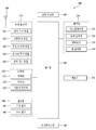
도 1는 본 출원에서 설명되는 이동 단말기의 구성(configuration)을 나타내는 블록도이다.
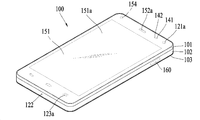
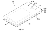
도 2 및 도 3은 이동 단말기의 일 예를 서로 다른 방향에서 바라본 사시도들이다.
도 4 및 도 5는 본 출원에 따른 안테나의 제 1 예를 나타내는 평면도 및 측면도이다.
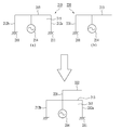
도 6은 제 1 예에 따른 안테나를 나타내는 회로도이다.
도 7은 제 1 예에 따른 안테나의 변형예를 나타내는 평면도이다.
도 8은 제 1 예에 따른 안테나의 추가 변형예를 나타내는 평면도이다.
도 9는 이동 단말기에 적용된 제 1 예에 따른 안테나의 실제 예를 나타내는 평면도이다.
도 10은 제 1 예에 따른 안테나의 추가 변형예를 나타내는 평면도이다.
도 11은 이동 단말기에 적용된 도 10의 안테나의 실제 예를 나타내는 평면도이다.
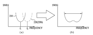
도 12는 본 출원의 안테나에 적용된 와이드 밴드를 보여주는 주파수에 대한 SWR(Standing Wave Ratio)의 그래프이다.
도 13은 본 출원의 안테나에 적용된 멀티밴드를 보여주는 주파수에 대한 SWR의 그래프이다.
도 14는 본 출원에 따른 안테나의 제 2 예를 나타내는 평면도이다.
도 15는 본 출원에 따른 안테나의 제 3 예를 나타내는 평면도이다.
도 16은 본 출원에 따른 안테나의 제 4 예를 나타내는 평면도이다. 1 is a block diagram illustrating a configuration of a mobile terminal as described in the present application.
2 and 3 are perspective views of an example of a mobile terminal viewed from different directions.
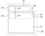
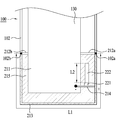
4 and 5 are a plan view and a side view showing a first example of the antenna according to the present application.
6 is a circuit diagram showing an antenna according to the first example.
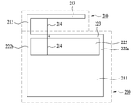
7 is a plan view showing a modified example of the antenna according to the first example.
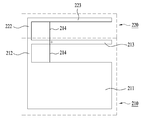
8 is a plan view showing a further modified example of the antenna according to the first example.
9 is a plan view showing an actual example of an antenna according to a first example applied to a mobile terminal.
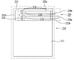
10 is a plan view showing a further modified example of the antenna according to the first example.
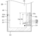
11 is a plan view showing an actual example of the antenna of Fig. 10 applied to a mobile terminal.
12 is a graph of SWR (Standing Wave Ratio) for a frequency showing a wide band applied to the antenna of the present application.
13 is a graph of SWR versus frequency showing the multi-band applied to the antenna of the present application.
14 is a plan view showing a second example of the antenna according to the present application.
15 is a plan view showing a third example of the antenna according to the present application.
16 is a plan view showing a fourth example of the antenna according to the present application.
이하, 첨부된 도면을 참조하여 본 명세서에 개시된 실시 예를 상세히 설명하되, 도면 부호에 관계없이 동일하거나 유사한 구성요소는 동일한 참조 번호를 부여하고 이에 대한 중복되는 설명은 생략하기로 한다. 이하의 설명에서 사용되는 구성요소에 대한 접미사 "모듈" 및 "부"는 명세서 작성의 용이함만이 고려되어 부여되거나 혼용되는 것으로서, 그 자체로 서로 구별되는 의미 또는 역할을 갖는 것은 아니다. 또한, 본 명세서에 개시된 실시 예를 설명함에 있어서 관련된 공지 기술에 대한 구체적인 설명이 본 명세서에 개시된 실시 예의 요지를 흐릴 수 있다고 판단되는 경우 그 상세한 설명을 생략한다. 또한, 첨부된 도면은 본 명세서에 개시된 실시 예를 쉽게 이해할 수 있도록 하기 위한 것일 뿐, 첨부된 도면에 의해 본 명세서에 개시된 기술적 사상이 제한되지 않으며, 본 발명의 사상 및 기술 범위에 포함되는 모든 변경, 균등물 내지 대체물을 포함하는 것으로 이해되어야 한다. Hereinafter, embodiments of the present invention will be described in detail with reference to the accompanying drawings, wherein like reference numerals are used to designate identical or similar elements, and redundant description thereof will be omitted. The suffix "module" and " part "for the components used in the following description are given or mixed in consideration of ease of specification, and do not have their own meaning or role. In the following description of the embodiments of the present invention, a detailed description of related arts will be omitted when it is determined that the gist of the embodiments disclosed herein may be blurred. It is to be understood that both the foregoing general description and the following detailed description are exemplary and explanatory and are intended to provide further explanation of the invention as claimed. , ≪ / RTI > equivalents, and alternatives.
제 1, 제 2 등과 같이 서수를 포함하는 용어는 다양한 구성요소들을 설명하는데 사용될 수 있지만, 상기 구성요소들은 상기 용어들에 의해 한정되지는 않는다. 상기 용어들은 하나의 구성요소를 다른 구성요소로부터 구별하는 목적으로만 사용된다.Terms including ordinals, such as first, second, etc., may be used to describe various elements, but the elements are not limited to these terms. The terms are used only for the purpose of distinguishing one component from another.
어떤 구성요소가 다른 구성요소에 "연결되어" 있다거나 "접속되어" 있다고 언급된 때에는, 그 다른 구성요소에 직접적으로 연결되어 있거나 또는 접속되어 있을 수도 있지만, 중간에 다른 구성요소가 존재할 수도 있다고 이해되어야 할 것이다. 반면에, 어떤 구성요소가 다른 구성요소에 "직접 연결되어" 있다거나 "직접 접속되어" 있다고 언급된 때에는, 중간에 다른 구성요소가 존재하지 않는 것으로 이해되어야 할 것이다.It is to be understood that when an element is referred to as being "connected" or "connected" to another element, it may be directly connected or connected to the other element, . On the other hand, when an element is referred to as being "directly connected" or "directly connected" to another element, it should be understood that there are no other elements in between.
단수의 표현은 문맥상 명백하게 다르게 뜻하지 않는 한, 복수의 표현을 포함한다. The singular expressions include plural expressions unless the context clearly dictates otherwise.
본 출원에서,"이루어진다(comprises)", "포함한다(include)" 또는 "가지다(have)" 등의 용어는 명세서상에 기재된 특징, 숫자, 단계, 동작, 구성요소, 부품 또는 이들을 조합한 것이 존재함을 지정하려는 것이지, 하나 또는 그 이상의 다른 특징들이나 숫자, 단계, 동작, 구성요소, 부품 또는 이들을 조합한 것들의 존재 또는 부가 가능성을 미리 배제하지 않는 것으로 이해되어야 한다. 또한, 같은 이유에서, 본 출원은 개시된 발명의 의도된 기술적 목적 및 효과에서 벗어나지 않는 한 앞선 언급된 용어를 사용하여 설명된 관련 특징, 숫자, 단계, 동작, 구성요소, 부품의 조합으로부터도 일부 특징, 숫자, 단계, 동작, 구성요소, 부품등이 생략된 조합도 포괄하고 있음도 이해되어야 한다. In this application, terms such as " comprises, "" including," or "having ", and the like are used interchangeably with a feature, a number, a step, an operation, an element, And does not preclude the presence or addition of one or more other features, numbers, steps, operations, components, components, or combinations thereof. Also for the same reason, this application is not to be construed as causing any adverse effect, either from a combination of the related features, numbers, steps, operations, elements, , Numbers, steps, operations, components, parts, and the like are also included.
본 명세서에서 언급되는 이동 단말기에는 휴대폰, 스마트 폰(smart phone), 노트북 컴퓨터(laptop computer), 디지털방송용 단말기, PDA(personal digital assistants), PMP(portable multimedia player), 네비게이션, 슬레이트 PC(slate PC), 태블릿 PC(tablet PC), 울트라북(ultrabook), 및 웨어러블 디바이스(wearable device, 예를 들어, 스마트 와치(smart wath), 글래스형 단말기 (smart glass), HMD(head mounted display)) 등이 포함될 수 있다. 그러나, 본 명세서에 기재된 실시 예에 따른 구성은 이동 단말기에만 적용 가능한 경우를 제외하면, 고정 단말기에도 적용될 수도 있음을 본 기술분야의 당업자라면 쉽게 알 수 있을 것이다.Mobile terminals as referred to herein include mobile phones, smart phones, laptop computers, digital broadcasting terminals, personal digital assistants (PDAs), portable multimedia players (PMPs), navigation, slate PCs, Tablet PCs, ultrabooks, and wearable devices such as smart wats, smart glasses, head mounted displays (HMDs), and the like . However, it will be readily apparent to those skilled in the art that the configuration according to the embodiment described herein may be applied to a fixed terminal, except when applicable only to a mobile terminal.
먼저 본 출원에서 설명되는 이동 단말기의 일 예의 전체적인 구성이 관련된 도면을 참조하여 다음에서 설명된다. 도 1은 본 출원과 관련된 이동 단말기를 설명하기 위한 블록도이며, 이를 참조하여 이동 단말기의 일반적인 구성(configuration)을 설명하면 다음과 같다.First, the overall configuration of an example of the mobile terminal described in the present application will be described below with reference to the related drawings. FIG. 1 is a block diagram for explaining a mobile terminal related to the present application, and a general configuration of a mobile terminal will be described with reference to FIG.
상기 이동 단말기(100)는 무선 통신부(110), 입력부(120), 감지부(140), 출력부(150), 인터페이스부(160), 메모리(170), 제어부(180) 및 전원 공급부(190) 등을 포함할 수 있다. 도 1에 도시된 구성요소들은 이동 단말기(100)를 구현하는데 있어서 필수적인 것은 아니어서, 본 명세서 상에서 설명되는 이동 단말기(100)는 위에서 열거된 구성요소들 보다 많거나, 또는 적은 구성요소들을 가질 수 있다. 또한, 앞서 언급된 구성요소들의 실제 형상 및 구조가 모두 도시되지는 않으며, 중요한 일부 구성요소들의 형상 및 구조만이 도 1에 뒤따르는 도면들에서 나타난다. 그러나, 이동 단말기(100)로서의 기능을 구현하기 위해 비록 모두 도시되지는 않지만 설명된 구성요소들이 이동 단말기(100)에 포함될 수 있음을 당업자는 이해 가능하다.The
보다 구체적으로, 상기 구성요소들 중 무선 통신부(110)는, 이동 단말기(100)와 무선 통신 시스템 사이, 이동 단말기(100)와 다른 이동 단말기(100) 사이, 또는 이동 단말기(100)와 외부서버 사이의 무선 통신을 가능하게 하는 하나 이상의 모듈을 포함할 수 있다. 또한, 상기 무선 통신부(110)는, 이동 단말기(100)를 하나 이상의 네트워크에 연결하는 하나 이상의 모듈을 포함할 수 있다.The
이러한 무선 통신부(110)는, 방송 수신 모듈(111), 이동통신 모듈(112), 무선 인터넷 모듈(113), 근거리 통신 모듈(114), 위치정보 모듈(115) 중 적어도 하나를 포함할 수 있다.The
입력부(120)는, 영상 신호 입력을 위한 카메라(121) 또는 영상 입력부, 오디오 신호 입력을 위한 마이크로폰(microphone, 122), 또는 오디오 입력부, 사용자로부터 정보를 입력받기 위한 사용자 입력부(123, 예를 들어, 터치키(touch key), 푸시키(mechanical key) 등)를 포함할 수 있다. 입력부(120)에서 수집한 음성 데이터나 이미지 데이터는 분석되어 사용자의 제어명령으로 처리될 수 있다.The
센싱부(140)는 이동 단말기 내 정보, 이동 단말기를 둘러싼 주변 환경 정보 및 사용자 정보 중 적어도 하나를 센싱하기 위한 하나 이상의 센서를 포함할 수 있다. 예를 들어, 센싱부(140)는 근접센서(141, proximity sensor), 조도 센서(142, illumination sensor), 터치 센서(touch sensor), 가속도 센서(acceleration sensor), 자기 센서(magnetic sensor), 중력 센서(G-sensor), 자이로스코프 센서(gyroscope sensor), 모션 센서(motion sensor), RGB 센서, 적외선 센서(IR 센서: infrared sensor), 지문인식 센서(finger scan sensor), 초음파 센서(ultrasonic sensor), 광 센서(optical sensor, 예를 들어, 카메라(121 참조)), 마이크로폰(microphone, 122 참조), 배터리 게이지(battery gauge), 환경 센서(예를 들어, 기압계, 습도계, 온도계, 방사능 감지 센서, 열 감지 센서, 가스 감지 센서 등), 화학 센서(예를 들어, 전자 코, 헬스케어 센서, 생체 인식 센서 등) 중 적어도 하나를 포함할 수 있다. 본 명세서에 개시된 이동 단말기는, 이러한 센서들 중 적어도 둘 이상의 센서에서 센싱되는 정보들을 조합하여 활용할 수 있다.The
출력부(150)는 시각, 청각 또는 촉각 등과 관련된 출력을 발생시키기 위한 것으로, 디스플레이부(151), 음향 출력부(152), 햅팁 모듈(153), 광 출력부(154) 중 적어도 하나를 포함할 수 있다. 디스플레이부(151)는 터치 센서와 상호 레이어 구조를 이루거나 일체형으로 형성됨으로써, 터치 스크린을 구현할 수 있다. 이러한 터치 스크린은, 이동 단말기(100)와 사용자 사이의 입력 인터페이스를 제공하는 사용자 입력부(123)로써 기능함과 동시에, 이동 단말기(100)와 사용자 사이의 출력 인터페이스를 제공할 수 있다.The
인터페이스부(160)는 이동 단말기(100)에 연결되는 다양한 종류의 외부 기기와의 통로 역할을 수행한다. 이러한 인터페이스부(160)는, 유/무선 헤드셋 포트(port), 외부 충전기 포트(port), 유/무선 데이터 포트(port), 메모리 카드(memory card) 포트, 식별 모듈이 구비된 장치를 연결하는 포트(port), 오디오 I/O(Input/Output) 포트(port), 비디오 I/O(Input/Output) 포트(port), 이어폰 포트(port) 중 적어도 하나를 포함할 수 있다. 이동 단말기(100)는, 상기 인터페이스부(160)에 외부 기기가 연결되는 것에 대응하여, 연결된 외부 기기와 관련된 적절할 제어를 수행할 수 있다.The
또한, 메모리(170)는 이동 단말기(100)의 다양한 기능을 지원하는 데이터를 저장한다. 메모리(170)는 이동 단말기(100)에서 구동되는 다수의 응용 프로그램(application program 또는 애플리케이션(application)), 이동 단말기(100)의 동작을 위한 데이터들, 명령어들을 저장할 수 있다. 이러한 응용 프로그램 중 적어도 일부는, 무선 통신을 통해 외부 서버로부터 다운로드 될 수 있다. 또한 이러한 응용 프로그램 중 적어도 일부는, 이동 단말기(100)의 기본적인 기능(예를 들어, 전화 착신, 발신 기능, 메시지 수신, 발신 기능)을 위하여 출고 당시부터 이동 단말기(100)상에 존재할 수 있다. 한편, 응용 프로그램은, 메모리(170)에 저장되고, 이동 단말기(100) 상에 설치되어, 제어부(180)에 의하여 상기 이동 단말기의 동작(또는 기능)을 수행하도록 구동될 수 있다.In addition, the
제어부(180)는 상기 응용 프로그램과 관련된 동작 외에도, 통상적으로 이동 단말기(100)의 전반적인 동작을 제어한다. 제어부(180)는 위에서 살펴본 구성요소들을 통해 입력 또는 출력되는 신호, 데이터, 정보 등을 처리하거나 메모리(170)에 저장된 응용 프로그램을 구동함으로써, 사용자에게 적절한 정보 또는 기능을 제공 또는 처리할 수 있다.In addition to the operations related to the application program, the
또한, 제어부(180)는 메모리(170)에 저장된 응용 프로그램을 구동하기 위하여, 도 1와 함께 살펴본 구성요소들 중 적어도 일부를 제어할 수 있다. 나아가, 제어부(180)는 상기 응용 프로그램의 구동을 위하여, 이동 단말기(100)에 포함된 구성요소들 중 적어도 둘 이상을 서로 조합하여 동작시킬 수 있다.In addition, the
전원공급부(190)는 제어부(180)의 제어 하에서, 외부의 전원, 내부의 전원을 인가 받아 이동 단말기(100)에 포함된 각 구성요소들에 전원을 공급한다. 이러한 전원공급부(190)는 배터리를 포함하며, 상기 배터리는 내장형 배터리 또는 교체가능한 형태의 배터리가 될 수 있다.The
상기 각 구성요소들 중 적어도 일부는, 이하에서 설명되는 다양한 실시 예들에 따른 이동 단말기의 동작, 제어, 또는 제어방법을 구현하기 위하여 서로 협력하여 동작할 수 있다. 또한, 상기 이동 단말기의 동작, 제어, 또는 제어방법은 상기 메모리(170)에 저장된 적어도 하나의 응용 프로그램의 구동에 의하여 이동 단말기 상에서 구현될 수 있다. At least some of the components may operate in cooperation with one another to implement a method of operation, control, or control of a mobile terminal according to various embodiments described below. In addition, the operation, control, or control method of the mobile terminal may be implemented on the mobile terminal by driving at least one application program stored in the
뒤따르는 나머지 도면들에서 이동 단말기(100)는 바(bar) 형태의 몸체를 가지는 것으로 도시된다. 그러나, 본 출원에서 설명되는 예는 여기에 한정되지 않고, 다양한 구조 및 형태를 가질 수 있다. 예를 들어, 이동 단말기(100)는 안경, 시계, 팔찌 및 목걸이와 같은 웨어러블 한 몸체를 가질 수 있다. 즉, 이동 단말기(100)의 특정 유형에 대한 구성 및 이에 대한 설명은 해당 이동 단말기(100)의 특정 유형 뿐만 아니라 다른 타입의 이동 단말기에도 일반적으로 적용될 수 있다. In the remaining figures that follow, the
상술된 이동 단말기(100)의 일반적인 구성에 뒤이어, 관련된 도면을 참조하여 이동 단말기(100)의 구조가 상세하게 설명된다. 이와 관련하여, 도 2 및 도 3은 이동 단말기의 일 예를 서로 다른 방향에서 바라본 사시도들이다. 보다 상세하게는, 도 2는 이동 단말기(100)의 전방부를 보여주는 사시도이며, 도 3은 이동 단말기(100)의 후방부를 보여주는 사시도이다. 도 2 및 도 3이 이동 단말기(100)의 전체적인 구조를 잘 보여주므로, 특별하게 참조할 도면이 언급될 때를 제외하고는 모든 설명들은 항상 도 2 및 도 3를 기본적으로 참조한다. Following the general construction of the
앞서 설명된 바와 같이, 이동 단말기(100)은 전체적으로 바 형태를 갖는 몸체를 가지고 있다. 몸체의 형상은 필요에 따라 다양하게 변화될 수 있다. 여기서, 몸체는 이동 단말기(100)를 적어도 하나의 집합체로 보아 이를 지칭하는 개념으로 이해될 수 있다. 따라서, 다음에서 설명되는 모든 구성요소들은 상기 이동 단말기(100)의 몸체에 제공 또는 설치되거나 상기 몸체내에 포함된다고 설명될 수 있다. As described above, the
이동 단말기(100)는 외관을 이루는 케이스(예를 들면, 프레임, 하우징, 커버 등)를 포함한다. 도시된 바와 같이, 이동 단말기(100)는 프론트 케이스(101)와 리어 케이스(102)를 포함할 수 있다. 프론트 케이스(101)와 리어 케이스(102)의 결합에 의해 형성되는 내부공간에는 각종 전자부품들이 배치될 수 있다. 결합된 이들 케이스들(101,102)은 또한 상기 이동 단말기(100)의 외형 또는 이의 몸체의 외형을 형성할 수 있다. 프론트 케이스(101)와 리어 케이스(102) 사이에는 적어도 하나의 미들 케이스가 추가로 배치될 수 있다.The
이동 단말기(100) 몸체의 전면에는 디스플레이부(151)가 배치되어 정보를 출력할 수 있다. 도시된 바와 같이, 디스플레이부(151)는 프론트 케이스(101)로부터 노출되며 이에 따라 프론트 케이스(101)와 함께 이동 단말기(100)의 전면을 형성할 수 있다.A
경우에 따라서, 리어 케이스(102)에도 전자부품이 장착될 수 있다. 리어 케이스(102)에 장착 가능한 전자부품은 착탈 가능한 배터리, 식별 모듈, 메모리 카드 등이 있다. 이 경우, 리어 케이스(102)에는 장착된 전자부품을 덮기 위한 후면커버(103)가 착탈 가능하게 결합될 수 있다. 따라서, 후면 커버(103)가 리어 케이스(102)로부터 분리되면, 리어 케이스(102)에 장착된 전자부품은 접근가능하도록 외부로 노출된다.In some cases, electronic components may also be mounted on the
도시된 바와 같이, 후면커버(103)가 리어 케이스(102)에 결합되면, 리어 케이스(102)의 측면 일부가 노출될 수 있다. 경우에 따라서, 상기 결합시 리어 케이스(102)는 후면커버(103)에 의해 완전히 가려질 수도 있다. 한편, 후면커버(103)에는 카메라(121b)나 음향 출력부(152b)를 외부로 노출시키기 위한 개구부가 구비될 수 있다.As shown, when the
이러한 케이스들(101, 102, 103)은 합성수지를 사출하여 형성되거나 금속, 예를 들어 스테인레스 스틸(STS), 알루미늄(Al), 티타늄(Ti) 등으로 형성될 수도 있다.These
이동 단말기(100)는, 복수의 케이스가 각종 전자부품들을 수용하는 내부 공간을 마련하는 위의 예와 달리, 하나의 케이스가 상기 내부 공간을 마련하도록 구성될 수도 있다. 이 경우, 합성수지 또는 금속이 측면에서 후면으로 이어지는 유니 바디의 이동 단말기(100)가 구현될 수 있다.The
한편, 이동 단말기(100)는 이의 몸체 내부로 물이 스며들지 않도록 하는 방수부(미도시)를 구비할 수 있다. 예를 들어, 방수부는 윈도우(151a)와 프론트 케이스(101) 사이, 프론트 케이스(101)와 리어 케이스(102) 사이 또는 리어 케이스(102)와 후면 커버(103) 사이에 구비되어, 이들의 결합 시 내부 공간을 밀폐하는 방수부재를 포함할 수 있다.Meanwhile, the
이동 단말기(100)에는 디스플레이부(151), 제1 및 제2 음향 출력부(152a, 152b), 근접 센서(141), 조도 센서(142), 광 출력부(154), 제1 및 제2 카메라(121a, 121b), 제1 및 제2 조작유닛(123a, 123b), 마이크로폰(122), 인터페이스부(160) 등이 구비될 수 있다.The
이하에서는, 도 2 및 도 3에 도시된 바와 같이, 이동 단말기(100) 몸체의 전면에 디스플레이부(151), 제1 음향 출력부(152a), 근접 센서(141), 조도 센서(142), 광 출력부(154), 제1 카메라(121a) 및 제1 조작유닛(123a)이 배치되고, 몸체의 측면에 제2 조작유닛(123b), 마이크로폰(122) 및 인터페이스부(160)이 배치되며, 몸체의 후면에 제2 음향 출력부(152b) 및 제2 카메라(121b)가 배치된 이동 단말기(100)를 일 예로 들어 설명한다.2 and 3, a
다만, 이들 구성은 이러한 배치에 한정되는 것은 아니다. 이들 구성은 필요에 따라 제외 또는 대체되거나, 다른 면에 배치될 수 있다. 예를 들어, 이동 단말기(100)의 몸체의 전면에는 제1 조작유닛(123a)이 구비되지 않을 수 있으며, 제2 음향 출력부(152b)는 몸체의 후면이 아닌 몸체의 측면에 구비될 수 있다.However, these configurations are not limited to this arrangement. These configurations may be excluded or replaced as needed, or placed on different planes. For example, the
디스플레이부(151)는 이동 단말기(100)에서 처리되는 정보를 표시(출력)한다. 예를 들어, 디스플레이부(151)는 이동 단말기(100)에서 구동되는 응용 프로그램의 실행화면 정보, 또는 이러한 실행화면 정보에 따른 UI(User Interface), GUI(Graphic User Interface) 정보를 표시할 수 있다. 또한, 이동 단말기(100)가 보조장치에 의해 사용자의 머리에 착용될 때, 디스플레이부(151)는 가상현실을 위한 입체영상을 사용자에게 제공할 수 있다. The
디스플레이부(151)는 액정 디스플레이(liquid crystal display, LCD), 박막 트랜지스터 액정 디스플레이(thin film transistor-liquid crystal display, TFT LCD), 유기 발광 다이오드(organic light-emitting diode, OLED), 플렉서블 디스플레이(flexible display), 3차원 디스플레이(3D display), 전자잉크 디스플레이(e-ink display) 중에서 적어도 하나를 포함할 수 있다. 디스플레이부(151)는 디스플레이 모듈(도시안됨)과 상기 디스플레이 모듈을 커버하는 윈도우(151a)를 포함할 수 있다. 디스플레이 모듈은 앞서 설명된 바와 같은 LCD, OLED와 같은 디스플레이 소자로 이루어질 수 있으며, 실제적으로 화상정보를 표시하는 구성요소이다. 윈도우(151a)는 디스플레이 모듈의 사용자에게 노출되는 부분에 배치될 수 있으며, 상기 디스플레이 모듈을 외부로부터 보호할 수 있다. 이러한 보호기능이외에도 윈도우(151a)는 이를 통해 디스플레이 모듈에 표시되는 정보를 사용에게 보여지게 허용해야 한다. 따라서, 윈도우(151a)는 적절한 강도 및 투명도를 갖는 재질로 이루어질 수 있다. 또한, 윈도우(151a)의 배면에 디스플레이 모듈이 직접적으로 부착될 수 있다. 디스플레이 모듈은 여러가지 방법으로 윈도우(151)에 직접 부착될 수 있으며, 접착제가 직접적 부착을 위해 가장 편리하게 사용될 수 있다. The
또한, 디스플레이부(151)는 이동 단말기(100)의 구현 형태에 따라 2개 이상 존재할 수 있다. 이 경우, 이동 단말기(100)에는 복수의 디스플레이부들이 하나의 면에 이격되거나 일체로 배치될 수 있고, 또한 서로 다른 면에 각각 배치될 수도 있다.In addition, the
디스플레이부(151)는 터치 방식에 의하여 제어 명령을 입력 받을 수 있도록, 디스플레이부(151)에 대한 터치를 감지하는 터치센서(미도시)를 포함할 수 있다. 상기 터치 센서는 저항막 방식, 정전용량 방식, 적외선 방식, 초음파 방식, 자기장 방식 등 여러 가지 터치방식 중 적어도 하나를 이용할 수 있다. 일 예로서, 저항막방식 및 정전용량 방식에서와 같이, 터치 센서는 터치 스크린의 특정 부위에 가해진 압력 또는 특정 부위에 발생하는 정전 용량 등의 변화를 전기적인 입력신호로 변환하도록 구성될 수 있다. 디스플레이부(151)는 터치 센서와 함께 이동 단말기에서 일종의 터치입력장치인 터치스크린을 구성할 수 있다. 디스플레이부(151)는 사용자 인터페이스인 터치스크린으로 작동하면서 동시에 소정의 화상정보를 표시할 수 있다. 즉, 디스플레이부(151)는 출력부(150) 뿐만 아니라 입력부(120)으로써도 기능할 수 있다. 디스플레이부(151)에 대하여 터치가 이루어지면, 터치센서는 상기 터치를 감지하고, 제어부(180)는 이에 근거하여 상기 터치에 대응하는 제어명령을 발생시키도록 이루어질 수 있다. 터치 방식에 의하여 입력되는 내용은 문자 또는 숫자이거나, 각종 모드에서의 지시 또는 지정 가능한 메뉴항목 등일 수 있다.The
터치센서는, 터치패턴을 구비하는 필름 형태로 구성되어 윈도우(151a)와 윈도우(151a)의 배면상의 디스플레이 모듈사이에 배치되거나, 윈도우(151a)의 배면에 직접 패터닝되는 메탈 와이어가 될 수도 있다. 또는, 터치센서는 디스플레이 모듈와 일체로 형성될 수 있다. 예를 들어, 터치센서는, 디스플레이 모듈의 기판 상에 배치되거나, 디스플레이 모듈의 내부에 구비될 수 있다.The touch sensor may be formed of a film having a touch pattern and disposed between the
이처럼, 디스플레이부(151)는 터치센서와 함께 터치 스크린을 형성할 수 있으며, 이 경우에 터치 스크린은 사용자 입력부(123, 도 1 참조)로 기능할 수 있다. 필요에 따라, 터치 스크린인 디스플레이부(151)에 인접하게 물리적 키(예를 들어 푸쉬 키)가 사용자 입력부(123)로써 사용자의 편리한 입력을 위해 추가적으로 제공될 수도 있다.In this way, the
제 1 음향 출력부(152a)는 통화음을 사용자의 귀에 전달시키는 리시버(receiver)로 구현될 수 있으며, 제2 음향 출력부(152b)는 각종 알람음이나 멀티미디어의 재생음을 출력하는 라우드 스피커(loud speaker)의 형태로 구현될 수 있다.The first
디스플레이부(151)의 윈도우(151a)에는 제1 음향 출력부(152a)로부터 발생되는 사운드의 방출을 위한 음향홀이 형성될 수 있다. 다만, 본 발명은 이에 한정되는 것은 아니고, 상기 사운드는 구조물 간의 조립틈(예를 들어, 윈도우(151a)와 프론트 케이스(101) 간의 틈)을 따라 방출되도록 구성될 수 있다. 이 경우, 외관상 음향 출력을 위하여 독립적으로 형성되는 홀이 보이지 않거나 숨겨져 이동 단말기(100)의 외관이 보다 심플해질 수 있다.The
광 출력부(154)는 이벤트의 발생시 이를 알리기 위한 빛을 출력하도록 이루어진다. 상기 이벤트의 예로는 메시지 수신, 호 신호 수신, 부재중 전화, 알람, 일정 알림, 이메일 수신, 애플리케이션을 통한 정보 수신 등을 들 수 있다. 제어부(180)는 사용자의 이벤트 확인이 감지되면, 빛의 출력이 종료되도록 광 출력부(154)를 제어할 수 있다.The
제1 카메라(121a)는 촬영 모드 또는 화상통화 모드에서 이미지 센서에 의해 얻어지는 정지영상 또는 동영상의 화상 프레임을 처리한다. 처리된 화상 프레임은 디스플레이부(151)에 표시될 수 있으며, 메모리(170)에 저장될 수 있다.The
제1 및 제2 조작유닛(123a, 123b)은 이동 단말기(100)의 동작을 제어하기 위한 명령을 입력 받기 위해 조작되는 사용자 입력부(123)의 일 예로서, 조작부(manipulating portion)로도 통칭될 수 있다. 제1 및 제2 조작유닛(123a, 123b)은 터치, 푸시, 스크롤 등 사용자가 촉각적인 느낌을 받으면서 조작하게 되는 방식(tactile manner)이라면 어떤 방식이든 채용될 수 있다. 또한, 제1 및 제2 조작유닛(123a, 123b)은 근접 터치(proximity touch), 호버링(hovering) 터치 등을 통해서 사용자의 촉각적인 느낌이 없이 조작하게 되는 방식으로도 채용될 수 있다.The first and
본 도면에서는 제1 조작유닛(123a)이 터치키(touch key)인 것으로 예시하나, 본 발명이 이에 한정되는 것은 아니다. 예를 들어, 제1 조작유닛(123a)은 푸시키(mechanical key)가 되거나, 터치키와 푸시키의 조합으로 구성될 수 있다.In this figure, the
제1 및 제2 조작유닛(123a, 123b)에 의하여 입력되는 내용은 다양하게 설정될 수 있다. 예를 들어, 제1 조작유닛(123a)은 메뉴, 홈키, 취소, 검색 등의 명령을 입력 받고, 제2 조작유닛(123b)은 제1 또는 제2 음향 출력부(152a, 152b)에서 출력되는 음향의 크기 조절, 디스플레이부(151)의 터치 인식 모드로의 전환 등의 명령을 입력 받을 수 있다.The contents input by the first and
상기 조작유닛(123a, 123b)은 앞서 설명된 디스플레이부(151)에 적용된 터치 스크린과 유사한 구조의 터치입력장치로 이루어질 수 있다. 조작유닛(123a, 123b)은 터치스크린과는 달리 화상정보의 표시없이 단순하게 명령만을 입력하도록 구성되며, 이와 같은 조작유닛에 적용된 터치입력장치는 터치패드라고 불릴 수 있다. The
한편, 이동 단말기(100) 몸체의 후면에는 사용자 입력부(123)의 다른 일 예로서, 후면 입력부(미도시)가 구비될 수 있다. 이러한 후면 입력부는 이동 단말기(100)의 동작을 제어하기 위한 명령을 입력 받기 위해 조작되는 것으로서, 입력되는 내용은 다양하게 설정될 수 있다. 예를 들어, 전원의 온/오프, 시작, 종료, 스크롤 등과 같은 명령, 제1 및 제2 음향 출력부(152a, 152b)에서 출력되는 음향의 크기 조절, 디스플레이부(151)의 터치 인식 모드로의 전환 등과 같은 명령을 입력 받을 수 있다. 후면 입력부는 터치입력, 푸시입력 또는 이들의 조합에 의한 입력이 가능한 형태로 구현될 수 있다.Meanwhile, a rear input unit (not shown) may be provided on the rear surface of the body of the
후면 입력부는 단말기(100) 몸체의 두께방향으로 전면의 디스플레이부(151)와 중첩되게 배치될 수 있다. 일 예로, 사용자가 단말기(100) 몸체를 한 손으로 쥐었을 때 검지를 이용하여 용이하게 조작 가능하도록, 후면 입력부는 단말기(100) 몸체의 후면 상단부에 배치될 수 있다. 다만, 본 발명은 반드시 이에 한정되는 것은 아니며, 후면 입력부의 위치는 변경될 수 있다.The rear input unit may be disposed so as to overlap with the
이처럼 단말기(100) 몸체의 후면에 후면 입력부가 구비되는 경우, 이를 이용한 새로운 형태의 유저 인터페이스가 구현될 수 있다. 또한, 앞서 설명한 터치 스크린 또는 후면 입력부가 단말기(100) 몸체의 전면에 구비되는 제1 조작유닛(123a)의 적어도 일부 기능을 대체하여, 상기 몸체의 전면에 제1 조작유닛(123a)이 미배치되는 경우, 디스플레이부(151)가 보다 큰 화면으로 구성될 수 있다.When a rear input unit is provided on the rear surface of the body of the terminal 100, a new type of user interface using the rear input unit can be realized. In addition, the above-described touch screen or rear input unit replaces at least a part of the functions of the
한편, 이동 단말기(100)에는 사용자의 지문을 인식하는 지문인식센서가 구비될 수 있으며, 제어부(180)는 지문인식센서를 통하여 감지되는 지문정보를 인증수단으로 이용할 수 있다. 상기 지문인식센서는 디스플레이부(151) 또는 사용자 입력부(123)에 내장될 수 있다.Meanwhile, the
마이크로폰(122)은 사용자의 음성, 기타 소리 등을 입력 받도록 이루어진다. 마이크로폰(122)은 복수의 개소에 구비되어 스테레오 음향을 입력 받도록 구성될 수 있다.The
인터페이스부(160)는 이동 단말기(100)를 외부기기와 연결시킬 수 있는 통로가 된다. 예를 들어, 인터페이스부(160)는 다른 장치(예를 들어, 이어폰, 외장 스피커)와의 연결을 위한 접속단자(예를 들어, USB 포트), 근거리 통신을 위한 포트[예를 들어, 적외선 포트(IrDA Port), 블루투스 포트(Bluetooth Port), 무선 랜 포트(Wireless LAN Port) 등], 또는 이동 단말기(100)에 전원을 공급하기 위한 전원공급단자 중 적어도 하나일 수 있다. 이러한 인터페이스부(160)는 SIM(Subscriber Identification Module) 또는 UIM(User Identity Module), 정보 저장을 위한 메모리 카드 등의 외장형 카드를 수용하는 소켓의 형태로 구현될 수도 있다.The
이동 단말기(100) 몸체의 후면에는 제2카메라(121b)가 배치될 수 있다. 이 경우, 제2카메라(121b)는 제1카메라(121a)와 실질적으로 반대되는 촬영 방향을 가지게 된다.And a
제2카메라(121b)는 적어도 하나의 라인을 따라 배열되는 복수의 렌즈를 포함할 수 있다. 복수의 렌즈는 행렬(matrix) 형식으로 배열될 수도 있다. 이러한 카메라는, 어레이 카메라로 명명될 수 있다. 제2카메라(121b)가 어레이 카메라로 구성되는 경우, 복수의 렌즈를 이용하여 다양한 방식으로 영상을 촬영할 수 있으며, 보다 나은 품질의 영상을 획득할 수 있다. 제1 카메라(121a)도 이와 같은 어레이 카메라로 구성될 수 있다. The
플래시(124)는 제2카메라(121b)에 인접하게 배치될 수 있다. 플래시(124)는 제2카메라(121b)로 피사체를 촬영하는 경우에 피사체를 향하여 빛을 비추게 된다. 또한, 이동 단말기(100)는 제 2 카메라(121b)에 인접하게 배치되는 거리센서를 포함할 수 있다. 거리센서는 이동 단말기(100)에 전방에 배치되는 근접센서(141)와 유사하게 소정 물체와 이동 단말기(100) 사이의 거리를 측정할 수 있다. 측정된 거리는 제 2 카메라(121b)에서 상기 물체에 대한 적절한 화상을 획득하는데 이용될 수 있으며, 또한 다른 여러가지 목적으로 활용될 수도 있다. The
이동 단말기(100) 몸체에는 제2 음향 출력부(152b)가 추가로 배치될 수 있다. 제2 음향 출력부(152b)는 제1 음향 출력부(152a)와 함께 스테레오 기능을 구현할 수 있으며, 통화시 스피커폰 모드의 구현을 위하여 사용될 수도 있다.A second
이동 단말기(100) 몸체에는 이동 단말기(100)에 전원을 공급하기 위한 전원 공급부(190, 도 1 참조)가 구비된다. 전원 공급부(190)는 상기 몸체에 내장되거나, 상기 몸체의 외부에서 착탈 가능하게 구성되는 배터리(191)를 포함할 수 있다.The body of the
배터리(191)는 인터페이스부(160)에 연결되는 전원 케이블을 통하여 전원을 공급받도록 구성될 수 있다. 또한, 배터리(191)는 무선충전기기를 통하여 무선충전 가능하도록 구성될 수도 있다. 상기 무선충전은 자기유도방식 또는 공진방식(자기공명방식)에 의하여 구현될 수 있다.The
본 도면에서는 후면 커버(103)가 배터리(191)를 덮도록 리어 케이스(102)에 결합되어 배터리(191)의 이탈을 제한하고, 배터리(191)를 외부 충격과 이물질로부터 보호하도록 구성된 것을 예시하고 있다. 배터리(191)가 몸체에 착탈 가능하게 구성되는 경우, 후면 커버(103)는 리어 케이스(102)에 착탈 가능하게 결합될 수 있다.In the figure, the
비록 도 2 및 도 3에는 도시되지 않았으나, 기판은 케이스들(101,102)내에 설치될 수 있으며, 각종 전자부품, 특히 제어부(180)를 구성하는 각종 프로세서들이 이들을 보조하는 다른 회로 및 소자들과 함께 장착되는 구성요소이다. 도 1에 도시된 각 구성요소들(110-190)은 제어부(180)에 의해 제어될 수 있도록 상기 기판에 직접 설치되거나, 상기 케이스(101,102)에 또는 그 내부에 설치되어 상기 기판에 전기적으로 연결된다. 예를 들어, 비록 외부에 노출되어 있지만, 윈도우(151)(즉, 터치센서) 및 디스플레이 모듈은 각각 배선을 통해 상기 기판에 연결될 수 있다. 따라서, 제어부(180)는 제어기(controller), 제어장치(controlling device)와 같은 다양한 명칭으로 불릴 수 있으며, 이동 단말기(100)의 모든 구성요소들을 제어할 수 있다. 이와 같은 제어되는 구성요소는 도 1에 포함된 구성요소 뿐만 아니라 다음에서 설명될 다른 구성요소들도 포함한다. Although not shown in FIGS. 2 and 3, the substrate may be installed in the
이동 단말기(100)에는 외관을 보호하거나, 이동 단말기(100)의 기능을 보조 또는 확장시키는 액세서리가 추가될 수 있다. 이러한 액세서리의 일 예로, 이동 단말기(100)의 적어도 일면을 덮거나 수용하는 커버 또는 파우치를 들 수 있다. 커버 또는 파우치는 디스플레이부(151)와 연동되어 이동 단말기(100)의 기능을 확장시키도록 구성될 수 있다. 액세서리의 다른 일 예로, 터치 스크린에 대한 터치입력을 보조 또는 확장하기 위한 터치펜을 들 수 있다.The
한편, 이동 단말기(100) 몸체에는 무선 통신을 위한 적어도 하나의 안테나(200:도 1 참조)가 구비될 수 있다. 안테나(200)는 일종의 에너지 변환 장치이며, 전자기파, 즉 전파를 방사하거나 수신하도록 구성될 수 있다. 보다 상세하게는, 전기적 신호는 전하와 전압에 의해 전달되므로, 전도체를 따라 이동할 수 있으나 부도체를 따라 이동할 수는 없다. 반면, 전자기파는 공기와 같은 부도체를 따라 이동할 수 있다. 따라서, 전기적 신호는 전자기파로 변화되어 공간을 통해 멀리 떨어진 곳으로 이동할 수 있다. 이러한 원리에 따라 안테나(200)는 전기적 신호를 전파로 변환하여 외부, 즉 공간을 통해 송신하며, 마찬가지로 상기 공간을 통해 전파를 수신하여, 전기적 신호로 변환할 수 있다. 따라서, 안테나(200)는 이동 단말기(100)가 외부장치 또는 네트워크와 통신할 수 있도록 전기적 신호를 송신하거나 수신할 수 있다. 이러한 안테나(200)는 무선통신부(110: 도 1 참조)의 일부를 형성할 수 있으며, 이동 단말기(100)의 몸체에 내장되거나, 케이스(101,102)에 형성될 수 있다. 예를 들어, 안테나(200)는 이동 단말기(100)의 몸체에서 인출 가능하게 구성될 수 있다. 또는, 안테나(200)는 필름 타입으로 형성되어 후면 커버(103)의 내측면에 부착될 수도 있다. Meanwhile, at least one antenna 200 (see FIG. 1) for wireless communication may be provided in the body of the
최근에 이동단말기(100)에는 금속재질의 케이스(101,102)가 적용되어 있다. 금속재질의 케이스(101,102)에 의해 이동 단말기(100)는 보다 좋은 외관을 가질 수 있으며, 보다 높은 강도를 가질 수 있다. 또한, 이러한 금속 케이스(101,102)는 충분한 전도성을 가지며, 전파의 송수신에 유리하도록 공기중에 노출되어 있다. 이러한 배치 및 재질 둘 다를 고려할 때, 금속 케이스(101,102)는 이동 단말기(100)의 안테나를 구성하기에 적합할 수 있다. 따라서, 금속 케이스(101,102)가 적용되는 경우, 이동 단말기(100)의 안테나(200)는 이러한 케이스(101,102)를 이용하여 구성될 수 있다. 그러나, 금속 케이스(101,102)에 의한 안테나(200)는 사용자의 신체, 특히 사용자의 손에 쉽게 접촉될 수 있으며, 이에 따라 소위 핸드 이펙트(hand effect)에 의해 이의 성능이 크게 저하될 수 있다. 보다 상세하게는, 핸드 이펙트에 있어서, 사용자의 신체도 일종의 도체이므로, 안테나(200)와 접촉되면 안테나(200)의 임피던스(impedance)가 변화하게 되며, 안테나(200)의 임피던스가 급전선(transmission line)의 임피던스와 매치되지 않을 수 있다. 이와 같은 미스매치(mismatch)로 인해, 안테나(200)의 방사효율이 저하되며 신호 또는 데이터의 송수신율이 크게 저하될 수 있다. 따라서, 이동 단말기(100)가 금속 케이스(101,102)를 이용하는 안테나(200)를 갖는 경우, 신체와의 접촉에 의한 성능저하는 최소화될 필요가 있다. 이러한 이유로, 본 출원에서 안테나(200)는 신체와의 접촉을 포함하는 다양한 작동환경하에서도 적어도 의도된 성능을 유지하도록 설계되며, 관련된 도면들을 참조하여 다음에서 상세하게 설명된다. Recently,
본 출원의 안테나(200)는 서로 다른 여러 예들로 구현될 수 있으며, 이들중에서 먼저 안테나(200)의 제 1 예가 설명된다. 상기 제 1 예(200)와 관련하여, 도 4 및 도 5는 본 출원에 따른 안테나의 제 1 예를 나타내는 평면도 및 측면도이며, 도 6은 제 1 예에 따른 안테나를 나타내는 회로도이다. 보다 상세하게는, 도 5은 도 4의 안테나를 "A" 방향에서 바라본 측면도이다. 또한, 도 2 및 도 3은 단말기(100)의 전체적인 구조를 잘 보여주므로, 설명의 편의를 위해 상기 도면들과 함께 다음의 설명에서 참조된다. The
상기 안테나(200)는 케이스(101,102)에 배치되는 제 1 안테나(210)와 상기 케이스(101,102)내부에 배치되는 제 2 안테나(220)를 포함할 수 있다. 앞서 설명된 바와 같이, 케이스(101,102)는 금속재질로 만들어지는 경우, 전파의 방사 및 수신에 유리한 재질 및 위치를 가질 수 있다. 따라서, 제 1 안테나(210)는 금속 케이스(101,102), 정확하게는 적어도 이의 일부를 이용하여 구성될 수 있으며, 이에 따라 상기 케이스(101,102) 자체에 배치될 수 있다. 또한, 제 1 안테나(210)는 이동 단말기(100)의 외형을 형성하는 케이스(101,102)의 일부에 해당하므로, 이러한 케이스(101,102)와 마찬가지로 이동 단말기(100)의 외부에 노출될 수 있다. 반면, 제 2 안테나(220)는 케이스(101,102)와 별도로 형성되어 케이스(101,102) 내부에 배치될 수 있다. 제 2 안테나(220)는 상기 케이스(101,102) 또는 커버(103)에 의해 덮혀지므로, 이동 단말기(100)로부터 노출되지 않을 수 있다. 이러한 제 1 및 제 2 안테나(220)의 배치에 의해, 적어도 제 2 안테나(220)는 케이스 및 커버(101,102,103)에 의해 신체와의 접촉으로부터 보호될 수 있다. 따라서, 이동단말기의 사용중 제 2 안테나(220)의 성능저하가 방지될 수 있다. 도 4-도 6은 개념적인 구조 및 회로를 도시하므로, 상술된 배치는 이들 도면에서 명확하게 도시되지 않을 수도 있으나 도 9 및 도 11 및 이들에 관련된 설명으로부터 명확하게 확인될 수 있다. The
또한, 안테나(200)는 기본적으로 안테나(200)의 회로에 전력 또는 전압을 공급하는 피드(feed)(214)를 공통적으로 포함할 수 있다. 만일 제 1 및 제 2 안테나(210,220)에 각각 피드들을 제공하는 경우, 안테나(200)의 회로는 복잡해질 수 있으며, 이동 단말기(100)자체의 회로설계에 대한 변경이 요구될 수도 있다. 이러한 이유로, 제 2 안테나(220)는 상기 제 1 안테나(210)에 직접적으로 결합될 수 있다. 이러한 직접적 결합은 도 6의 회로도로부터 보다 잘 이해될 수 있다. 보다 상세하게는, 제 1 안테나 및 제 2 안테나(210,220)는 이들의 직접적 결합에 의해 많은 구조를 공유할 수 있다. 도 6을 참조하면, 제 1 안테나(210)는 피드(214)를 필요로 하며(도 6(a) 참조), 이러한 피드는 제 2 안테나(220)의 작동을 위해서도 필수 불가결하다(도 6(b) 참조). 따라서, 앞서 언급된 바와 같이, 제 1 및 제 2 안테나들(210,220)이 서로 직접적으로 결합되면, 이들은 피드(214)를 서로 공유할 수 있다(도 6(c) 참조). 또한, 도 6(a) 및 도 6(b)에 도시된 바와 같이, 안테나(200)는 이의 회로를 보호하기 위한 그라운드(ground)(211)를 공통적으로 요구할 수 있다. 따라서, 같은 이유로, 제 1 및 제 2 안테나들(210,220)이 서로 직접적으로 결합되면, 이들은 그라운드(211)도 서로 공유할 수 있다(도 6(c) 참조). 이러한 직접적 결합에 의해 제 1 및 제 2 안테나(210,220)는 구조적 및 전기적으로 서로 결합될 수 있다. 즉, 제 1 및 제 2 안테나(210,220)는 기능적 측면에서만 서로 구별되며, 실제적으로 단일의 안테나(200)로서 형성된다. 따라서, 안테나(200)는 설계된 다양한 기능 또는 성능들을 제공하면서도 단순한 구조를 가질 수 있으며 생산 비용도 증가되지 않는다. 또한, 이러한 안테나(200)의 단순한 구조로 인해, 이동단말기(100)는 의도된 기능을 확보하면서도 컴팩트해 질 수 있다. In addition, the
상술된 안테나(200)의 기본적인 구성(configuration), 즉 기본적인 기능 및 구조에 뒤이어, 안테나(200)의 세부적인 구성이 다음에서 상세하게 설명된다. 안테나(200)에 있어서, 제 1 및 제 2 안테나(210,200)는 다양한 타입의 안테나들로 이루어질 수 있다, 이러한 안테나의 타입들중에서 슬롯안테나(slot amtenna) 및 IF 안테나(Inverted-F antenna)는 단순한 구조와 높은 방사효율을 가지므로, 이동 단말기(100)의 안테나에 적합할 수 있다. 또한, 슬롯 안테나는 기본적으로 전파방사를 위해 슬롯 구조를 필요로 한다. 케이스(101,102)는 도 2 및 도 3에 도시된 바와 같이, 일반적으로 사각형의 프레임으로 이루어지므로, 슬롯을 형성하기에 유리할 수 있다. 한편, IF 안테나는 전파 방사를 위해 소정 길이의 암(arm) 구조를 필요로 하며, 이러한 암 구조는 이동 단말기(100)의 좁은 내부공간내에 용이하게 배치될 수 있다. 이러한 이유로, 도 4-도 6에 도시된 바와 같이, 안테나(200)의 제 1 예에 있어서 케이스(101,102)를 이용하는 제 1 안테나(210)는 슬롯 안테나로 이루어질 수 있으며, 내부공간에 배치되는 제 2 안테나(220)는 IF 안테나로 이루어질 수 있다. 따라서, 다음에서는 도 4-도 6을 참조하여, 이와 같은 제 1 예에 따른 안테나(200)의 구조가 설명된다. Following the basic configuration, i.e., the basic functionality and structure of the
먼저, 제 1 안테나(210)는 슬롯 안테나로 이루어지며, 전류 및 전압으로 형성되는 전기적 신호의 이동을 위해 전체적으로 전도성 재질로 만들어질 수 있다. 제 1 안테나(210)는 안테나 회로를 보호하도록 이를 접지시키는 그라운드(211)을 포함할 수 있다. 제 1 안테나(210)는 또한, 그라운드(211)로부터 연장되는 한 쌍의 쇼팅 레그(shorting leg)(212a,212b)를 포함할 수 있다. 한 쌍의 레그(212a,212b)는 슬롯(215)를 형성하도록 서로 소정간격으로 이격될 수 있다. 상기 레그(212a,212b)는 적절한 방사를 위한 전압 및 전류차이를 안테나(200)에 발생시키기 위해 안테나의 회로를 단락시키는 역할을 수행한다. 제 1 안테나(210)은 또한, 레그(212a,212b)사이에서 연장되는 암(213)을 포함할 수 있다. 암(213)은 레그(212a,212b)와 각각 연결되며, 이에 따라 레그들(212a,212b) 및 그라운드(211)와 함께 슬롯(215)를 형성함으로서 전파를 방사할 수 있다. 제 1 안테나(210)는 상기 제 1 안테나(210)의 회로에 전력(즉, 전압)을 공급하도록 구성되는 피드(214)를 포함할 수 있다. 상기 슬롯(215)으로부터 전파가 방사될 수 있도록 피드(214)는 슬롯(215)를 가로지면서 연장되며, 그라운드(211)와 암(213)에 각각 연결될 수 있다. First, the
제 2 안테나(220)는 IFA 안테나로 이루어지며, 제 1 안테나(210)와 마찬가지로 전류 및 전압에 의해 형성되는 전기적 신호의 이동을 위해 전체적으로 전도성 재질로 만들어질 수 있다. 앞서 설명된 바와 같이, 제 2 안테나(220)는 제 1 안테나(220)에 직접적으로 결합 또는 연결될 수 있다. 보다 상세하게는, 도시된 바와 같이, 제 2 안테나(220)는 제 1 안테나(210)의 피드(214)에 직접적으로 연결될 수 있다. 따라서, 도시된 바와 같이, 제 2 안테나(220)는 일차적으로 제 1 안테나(210)와 피드(214)를 공유할 수 있다. 또한, 피드(214)를 통해 그라운드(211)까지 회로적으로 연결될 수 있으므로, 제 2 안테나(220)는 제 1 안테나(210)와 그라운드(211)도 공유할 수 있다. 다른 한편. 제 2 안테나(220)는 제 1 안테나(210)가 배치되는 평면(이하, 제 1 평면)과는 다른 평면(이하, 제 2 평면)내에 배치될 수 있다. 보다 상세하게는, 제 2 안테나(220)는 도 4 및 도 5에서 도시된 바와 같이, 제 1 평면으로부터 소정 간격으로 이격되며 제 1 안테나(210), 즉 제 1 평면 위에(above) 배치되는 제 2 평면내에 배치될 수 있다. 그러나, 비록 도시되지는 않았으나, 제 2 안테나(220)는 제 1 평면 아래(below)에 위치하는 제 2 평면내에 배치될 수도 있다. 즉, 제 2 안테나(220)는 제 1 안테나(210)와 소정간격을 유지하면서 제 1 안테나(210)에 적층되거나 이와 오버랩될 수 있다. 따라서, 이러한 배치에 의해 서로 결합된 제 1 및 제 2 안테나(210,220), 즉 제 1 예에 따른 안테나(200)는 컴팩트하게 형성될 수 있으며, 작은 크기를 갖는 이동 단말기(100)에 적용되기에 적합할 수 있다. The
도 4 - 도 6을 참조하면, 제 2 안테나(220)는 제 1 안테나(210)가 배치되는 제 1 평면으로부터 돌출되는 레그(221)을 포함할 수 있다. 레그(221)는 안테나의 회로를 단락시키며, 전파의 방사를 위해 전압 및 전류차이를 제 2 안테나(220)에 발생시킬 수 있다. 보다 상세하게는, 레그(221)는 피드(214)에 직접 연결되며, 상기 피드(214)로부터 돌출되도록 연장될 수 있다. 따라서, 제 2 안테나(220)도 제 1 안테나(210)와 함께 피드(214)로부터 전력을 공급받을 수 있으며, 이에 따라 제 1 안테나(210)와 피드(214)를 공유할 수 있다. 또한, 제 2 안테나(220)는 레그(221)로부터 연장되는 암(222)를 포함할 수 있다. 암(222)은 제 2 안테나(220)에서 실제적으로 전파를 방사하는 역할을 한다. 보다 상세하게는, 암(222)는 제 1 안테나(210)로부터 이격되면서 대체적으로 이에 평행하게 연장될 수 있다. 따라서, 제 2 안테나(220)는 대체적으로 제 1 안테나(210)의 제 1 평면에 평행한 제 2 평면내에 배치될 수 있다. 4 to 6, the
한편, 제 1 및 제 2 안테나(210,220)는 의도된 주파수의 전파 방사를 위해서는 소정의 길이를 가져야 한다. 예를 들어, 제 1 안테나(210)인 슬롯 안테나에서, 슬롯(215) 또는 암(213)의 길이(L1)은 λ/2로 설정되어야 한며, 여기서 λ는 전파의 파장에 해당한다. 또한, 제 2 안테나(220)인 IF 안테나에서, 암(222)의 길이(L2)는 λ/4로 설정되어야 한다. 즉, 슬롯/암(213) 및 암(222)의 길이(L1,L2)의 조절은 제 1 및 제 2 안테나(210,220)가 수신하거나 방사하는 전파의 주파수, 정확하게는 공진 주파수의 조절을 가져올 수 있다. 여기서, 공진 주파수는 안테나가 최대의 성능을 보여주는 주파수로 정의될 수 있다. 따라서, 길이(L1,L2)를 조절함으로써 제 1 및 제 2 안테나(210,220)는 의도된 성능을 갖도록 튜닝될 수 있다. 예를 들어, 튜닝을 위한 설계에 있어서, 길이(L1)이 고정된 값을 가질 때 상기 길이(L1)에 상대적으로 길이(L2)가 변경될 수 있다. 또한, 길이(L2)가 고정된 값을 가질 때, 상기 길이(L2)에 대해 길이(L1)이 상대적으로 변경될 수도 있다. Meanwhile, the first and
이와 같은 안테나의 튜닝이 관련된 도면들을 참조하여 다음에서 보다 상세하게 설명된다. 도 12는 본출원의 안테나에 적용된 와이드 밴드를 보여주는 주파수에 대한 SWR(Standing Wave Ratio)의 그래프이며, 도 13은 본 출원의 안테나에 적용된 멀티밴드를 보여주는 주파수에 대한 SWR의 그래프이다. 여기서, SWR은 안테나에서 수신 또는 방사되는 전력(또는 전압)의 최소값에 대한 이의 최대값의 비율로 정의 될 수 있다. 따라서, SWR의 값이 작다는 것은 안테나의 임피던수와 급전선의 임피던스가 잘 매치되며, 이에 따라 안테나가 좋은 성능을 내고 있다는 것을 의미할 수있다. 따라서, 안테나의 공진 주파수에서 SWR은 최소값을 나타낼 수 있다. 또한, 공진 주파수 부근의 일정 주파수 범위에서 안테나는 어느정도 좋은 성능을 보여줄 수 있으므로, 이러한 범위 또한 공진 주파수와 함께 안테나 성능의 기준이 될 수 있다. 이와 같은 주파수 범위는 공진 주파수 대역으로 정의되며, 도 12 및 도 13에 실선 또는 점선으로 표시된다. The tuning of such an antenna is described in more detail below with reference to the associated drawings. FIG. 12 is a graph of SWR (Standing Wave Ratio) versus frequency showing a wide band applied to the antenna of the present application, and FIG. 13 is a graph of SWR versus frequency showing multi-band applied to the antenna of the present application. Here, SWR can be defined as the ratio of the maximum value of the power (or voltage) received or radiated by the antenna to its minimum value. Therefore, a small value of SWR means that the impedance of the antenna matches the impedance of the feeder line, and thus the antenna is performing well. Therefore, at the resonance frequency of the antenna, SWR can represent the minimum value. Also, since the antenna can exhibit a somewhat good performance in a certain frequency range near the resonance frequency, this range can also be a reference for the antenna performance together with the resonance frequency. Such a frequency range is defined as a resonance frequency band, and is indicated by a solid line or a dotted line in Figs. 12 and 13.
안테나(200)의 튜닝에 있어서, 먼저 길이(L1,L2)의 조절에 따라 제 2 안테나(220)는 비록 도시되지는 않았지만 제 1 안테나(210)의 공진 주파수(f1)과 동일한 공진 주파수(f2)를 가질 수 있다. 따라서, 만일 제 1 안테나(210)가 신체와의 접촉으로 인해 낮은 성능으로 작동되어도 제 2 안테나(220)가 제 1 안테나(210)를 대신하여 의도된 성능으로 작동될 수 있다. The tuning of the
다른 한편, 도 12(a)에 도시된 바와 같이, 길이(L1,L2)의 조절에 의해, 제 2 안테나(220)는 제 1 안테나(210)의 공진 주파수(f1)에 인접하는 공진 주파수(f2)를 가질 수 있다. 이러한 공진 주파수들(f1,f2)은 서로 다르나 큰 차이를 가지지 않는다. 따라서, 도 12(b)에 도시된 바와 같이, 제 1 및 제 2 안테나(210,220)의 공진 주파수 대역(band)들이 서로 겹쳐지게 되며, 좋은 성능을 나타내는 대역폭이 실질적으로 확장되는 효과를 가져올 수 있다. 즉, 제 2 안테나(220)는 이의 공진주파수 대역이 제 1 안테나(210)의 공진 주파수 대역과 겹쳐지도록 상기 제 1 안테나(210)의 공진 주파수(f1)에 인접하게 설정되는 공진주파수(f2)를 가질 수 있다. 이러한 이유로, 안테나(220)는 하나의 와이드 밴드, 광대역(wide band)를 가질 수 있으며, 성능이 강화될 수 있다. 또 다른 한편, 도 13에 도시된 바와 같이, 길이(L1,L2)의 조절에 의해 제 2 안테나(220)의 공진 주파수(f2)은 제 1 안테나(210)의 공진 주파수(f1)와 큰 차이를 갖도록 설정될 수 있다. 따라서, 앞선 도 12의 예와는 다르게, 제 1 및 제 2 안테나(210,220)의 공진 주파수 대역(band)들은 서로 겹쳐지지 않으며, 서로 독립적으로 존재할 수 있다. 즉, 제 2 안테나(220)는 이의 공진주파수 대역이 제 1 안테나(210)의 공진 주파수 대역과 겹쳐지지 않도록 상기 제 1 안테나(210)의 공진 주파수(f1)에 대해 큰 차이를 갖는 공진주파수(f2)를 가질 수 있다. 이러한 이유로, 안테나(220)는 실제적으로 멀티 밴드, 즉 다중 대역(multi band) 특성을 가질 수 있으며, 다양한 대역의 신호들에 대해 적응성을 가질 수 있다. 따라서, 만일 신체접촉에 의해 제 1 안테나(210)의 성능이 저하되어도, 제 2 안테나(220)의 주파수 튜닝에 의한 멀티 밴드 또는 와이드 밴드 특성에 의해 제 1 안테나(210)의 성능 저하가 보상될 수 있다. 이러한 이유로, 신체접촉 및 다른 작동환경에 의해 제 1 안테나(210)의 성능저하에 상관없이 안테나(200) 전체적으로 성능을 유지할 수 있다. 더 나아가, 안테나(200)는 앞서 설명된 와이드 또는 멀티 밴드 특성을 가짐으로써 신체 접촉 및 다른 성능저하 조건들이 없는 정상적인 작동 환경하에서는 보다 향상된 성능을 이동 단말기(100)에 제공할 수 있다. 12 (a), by adjusting the lengths L1 and L2, the
앞서 설명된 안테나(200)의 제 1 예는 다양한 구조들로 변형될 수 있다. 도 7은 안테나의 제 1예에 대한 변형예를 나타내는 평면도이며, 도 8은 안테나의 제 1예에 대한 추가 변형예를 나타내는 평면도이다. 앞서 설명된 제 1 예의 기본적인 구성, 즉 기능 및 구조는 도 7 및 도 8의 변형례들에도 동일하게 적용될 수 있으므로, 이에 대한 추가적인 설명은 생략된다. 또한, 세부적인 구성에 있어서도, 변형예의 구성요소들은 앞서 설명된 해당 구성요소들과 동일한 기능을 가질 수 있다. 즉, 도 4 및 도 5를 참조하여 설명된 제 1 및 제 2 안테나의 그라운드, 레그, 암, 피드의 기능들은 도 7 및 도 8의 변형예들의 해당 구성요소들에 그대로 적용될 수 있다. 따라서, 다음에서는 변형예들의 구조만이 상세하게 설명된다. 더 나아가, 도 7 및 8이 변형예들도 도 4 및 5의 기본예, 즉 제 1 예와 같은 기본적인 구성을 가지므로, 안테나(200)의 튜닝도 특별한 변형없이 바로 변형예들에 적용될 수 있다. 따라서, 변형예의 튜닝은 다음에서 추가적으로 설명되지 않는다. The first example of the
먼저, 도 7에 도시된 바와 같이, 도 4 및 도 5의 기본예와는 다르게, 제 1 및 제 2 안테나(210,220)는 실질적으로 동일한 평면내에 배치될 수 있다. 보다 상세하게는, 제 2 안테나(220)는 제 1 안테나(210)와 동일 평면내에 배치되면서 제 1 안테나(210)의 외부에 배치될 수 있다. 이러한 배치를 위해, 제 2 안테나(220)의 레그(221)는 제 1 안테나(210)의 레그들(212a,212b)중 어느 하나라도 부터 제 1 안테나(210)의 외부를 향해 소정의 길이로 연장될 수 있다. 또한, 제 2 안테나(220)의 암(222)은 상기 레그(221)로부터 제 1 안테나(210)와 동일평면내에서 제 1 안테나(210)의 암(213)과 대체적으로 평행하게 연장될 수 있다. 제 2 안테나(220)에 전력을 공급하기 위해 피드(214)는 제 1 안테나의 암(213)을 넘어 제 2 안테나(220)의 암(222)까지 연장될 수 있으며, 이에 따라 제 1 및 제 2 안테나(210,220)은 상기 피드(214) 및 그라운드(211)을 공유할 수 있다. 이와 같은 구조에 따라, 도 7의 변형예에서, 제 1 안테나(210)의 암(213), 레그(212) 및 슬롯(215)은 그라운드(211)와 제 2 안테나(220)사이에 배치될 수 있다. 또한, 암(213) 및 슬롯(215)는 제 1 안테나(210)에서 전파를 방사하는 실질적인 구성요소에 해당하므로, 제 1 안테나(210)자체가 제 2 안테나(220)와 그라운드(211)사이에 배치된다고 설명될 수 있다. First, as shown in FIG. 7, unlike the basic examples of FIGS. 4 and 5, the first and
또한, 도 8에 도시된 바와 같이, 도 7의 변형예와 마찬가지로 제 1 및 제 2 안테나(210,220)는 실질적으로 동일한 평면내에 배치될 수 있다. 또한, 제 2 안테나(220)는 제 1 안테나(210)와 동일 평면내에 배치되면서 제 1 안테나(210)의 내부에 배치될 수 있다. 이러한 배치를 위해, 먼저 제 1 안테나(210)는 그라운드(211)과 동일 평면내에 배치되면서 상기 그라운드(211)로부터 소정 간격으로 이격될 수 있다. 즉, 제 1 안테나(210)의 실질적인 구성요소들인 레그(212a,212b), 암(213a,213b) 및 슬롯(215)이 그라운드(211)로부터 소정간격으로 이격될 수 있다. 보다 상세하게는, 먼저 한쌍의 암들(213a,213b)이 소정간격으로 이격되면서 그라운드(211)와 동일한 평면내에서 서로 대체적으로 평행하게 연장될 수 있다. 이들 암들(213a,213b)은 그라운드(211)로부터도 소정 간격으로 이격될 수 있다. 또한, 한 쌍의 레그들(212a,212b)들은 암들(213a,213b)의 양 끝단들에 각각 배치될 수 있다. 따라서, 이들 암들(213a,213b) 및 레그들(212a,212b)에 의해 폐쇄된 슬롯(215)이 그라운드(211)와 이격된 위치에 형성될 수 있다. 상기 레그들(212a,212b)중 어느 하나는 접지를 위해 그라운드(211)과 연결될 수 있다. 한편, 제 2 안테나(220)의 레그(221)는 제 1 안테나(210)의 레그들(212a,212b)중 그라운드(211)와 연결되지 않는 다른 하나로부터 또는 암(213b)로부터 그라운드(211)를 향해 소정의 길이로 연장될 수 있다. 또한, 제 2 안테나(220)의 암(222)은 상기 레그(221)로부터 제 1 안테나(210)와 동일평면내에서 제 1 안테나(210)의 암(213)과 대체적으로 평행하게 연장될 수 있다. 제 2 안테나(220)에 전력을 공급하기 위해 피드(214)는 제 1 안테나의 암(213b)을 넘어 제 2 안테나(220)의 암(222)까지 연장될 수 있으며, 이에 따라 제 1 및 제 2 안테나(210,220)은 상기 피드(214) 및 그라운드(211)을 공유할 수 있다. 이와 같은 구조에 따라, 도 8의 변형예에서, 제 2 안테나(220)의 암(222) 및 레그(221)는 그라운드(211)와 제 1 안테나(210)의 슬롯(215), 암(213a,213b) 및 레그(212a,212b)사이에 배치될 수 있다. 암(222) 및 레그(221)가 제 2 안테나(220)의 실질적인 구성요소들이 되며, 슬롯(215), 암(213a,213b) 및 레그(212a,212b)가 제 1 안테나(210)의 실질적인 구성요소가 되므로, 제 2 안테나(220)자체가 제 1 안테나(220)와 그라운드(211)사이에 배치된다고 설명될 수 있다. 또한, 슬롯(215), 암(213a,213b) 및 레그(212a,212b)은 그라운드(211)와 함께 제 1 안테나(210)을 형성할 수 있으므로, 제 2 안테나(220)는 제 1 안테나(210)에 의해 감싸지거나 제 1 안테나(210)내에 배치된다고 설명될 수도 있다. Also, as shown in FIG. 8, the first and
제 1 예에 따른 안테나(200) 및 이의 변형예들이 실제적으로 이동 단말기(100)에 적용될 때, 이들은 앞서 설명된 개념적 구성들을 유지하면서도 상기 이동 단말기(100)의 설계 및 구조에 따라 도 4-도 8에 도시된 개념적인 구조와는 다른 실제적인 구조를 가질 수 있다. 따라서, 다음에서는 관련된 도면을 참조하여 안테나(200)의 실제 예가 상세하게 설명된다. 도 9는 이동 단말기에 적용된 제 1 예에 따른 안테나의 실제 예를 나타내는 평면도이다. 또한, 도 10은 제 1 예에 따른 안테나의 추가 변형예를 나타내는 평면도이며, 도 11은 이동 단말기에 적용된 도 10의 안테나의 실제 예를 나타내는 평면도이다. 다음에서 설명되는 실제예는 도 4 및 도 5에 도시된 제 1 예에 따른 안테나(200), 즉 기본예에 관한 것이다. 그러나, 도 7 및 도 8의 변형예도 특별한 변형없이 상기 실제예로부터 실제적으로 구현될 수 있음은 당업자에게 자명하다. When the
먼저 도 9는 도 2의 이동 단말기(100)으로부터 커버(103)가 제거된 후방부를 도시한다. 커버(103)의 제거로 인해, 케이스(102)의 후방부가 노출되며, 기판(130) 또한 함께 노출될 수 있다. 먼저, 제 1 안테나(210)에 있어서, 그라운드(211)는 기판(130)의 일부로 이루어질 수 있다. 실제적으로, 이동 단말기(130)도 회로의 보호를 위해 기판(130)에 그라운드를 포함하며, 안테나(200)도 이러한 이동 단말기(100)의 그라운드를 공유할 수도 있다. 앞서 설명된 바와 같이, 암(213)은 실제적으로 제 1 안테나(210)에서 전파를 수신하거나 방사하는 구성요소이다. 이와 관련하여, 케이스(102)는 전파방사에 적합한 금속재질로 이루어지며, 이동 단말기(100)의 외부로 노출된다. 따라서, 제 1 안테나(210)에서 암(213)이 상기 케이스(102)를 이용하여 구현될 수 있다. 보다 상세하게는, 한 쌍의 레그(212a,212b)가 그라운드(211)인 기판(130)으로부터 케이스(102)까지 연장될 수 있다. 이러한 레그들(212a,212b)의 배치에 의해 사선으로 표시된 바와 같이, 어느 한 레그(212a)가 케이스(102)에 연결된 지점(102a)로부터 다른 한 레그(212b)가 케이스(102)에 연결된 지점(102b)사이의 케이스(102)의 일부가 암(213)으로서 기능할 수 있다. 또한, 마찬가지로 사선으로 표시된 바와 같이, 레그(212a,212b), 케이스(102)의 일부, 즉 암(213), 및 상기 케이스(102)의 일부와 마주하는 기판(130)의 일부, 즉 그라운드(211)에 의해 슬롯(215)이 형성될 수 있다. 더 나아가, 형성된 슬롯(215)를 가로질러 피드(214)가 기판(130)의 일부인 그라운드(211)와 케이스(102)의 일부인 암(213)을 연결하며, 제 1 안테나(210)에 전력을 공급할 수 있다. 이러한 피드(214)는 기판(130)에 형성된 전원 단자에 연결될 수 있으며, 이동 단말기(100)와 전원을 공유할 수 있다. 상기 연결지점(102a,102b)을 변경함으로써 암(213) 및 슬롯(215)의 길이(L1: 도 4 참조)가 변경될 수 있으며, 이에 따라 제 1 안테나(210)의 공진 주파수가 변경될 수 있다. 따라서, 상기 연결지점(102a,102b), 즉 레그(212a,212b)의 위치를 조절함으로써 제 1 안테나(210)는 원하는 성능을 내도록 튜닝될 수 있다. First, Fig. 9 shows a rear portion from which the
제 2 안테나(220)의 레그(221)는 피드(214)에 연결되며, 제 1 안테나(210)가 배치되는 제 1 평면, 즉 기판(130) 또는 케이스(102)로부터 돌출될 수 있다. 또한, 제 2 안테나(220)의 암(222)는 제 1 평면, 즉 기판(130) 또는 케이스(102)의 노출된 후방면에 대체적으로 평행하게 연장될 수 있다. 따라서, 제 2 안테나(220)는 기판(130)과 케이스(102)사이의 공간상에 배치될 수 있으며, 사용되지 않는 이동 단말기(100)의 내부공간을 효과적으로 활용할 수 있다. 이미 앞서 관련된 도면을 참조하여 상세하게 설명된 바와 같이, 제 2 안테나(220), 더 나아가 안테나(200)가 전체적으로 의도된 성능을 낼 수 있도록 제 2 안테나(220)는 이의 길이(L2: 도 4 참조)를 조절함으로써 튜닝될 수 있다. 보다 상세하게는, 만일 제 1 안테나(210)이 기 설정된 길이(L1)에 따른 일정 고정 주파수(f1)을 갖는 경우, 제 2 안테나(220)는 길이(L2)를 조절함으로써 제 1 안테나(210)의 공진 주파수(f1)과 동일한 공진 주파수(f2)를 가질 수 있다, 이러한 제 2 안테나(210)는 신체접촉에 의해 낮은 성능을 가질 수 있는 제 1 안테나(210)를 대신하여 의도된 성능으로 작동될 수 있다. 다른 한편, 도 12(a)에 도시된 바와 같이, 길이(L2)의 조절에 의해 제 2 안테나(220)는 공진 주파수(f1)에 인접하는 공진 주파수(f2)를 가질 수 있으며, 이에 따라 도 12(b)에 도시된 바와 같이, 안테나(200)는 전체적으로 와이드 밴드 특성을 가질 수 있다. 또 다른 한편, 도 13에 도시된 바와 같이, 길이(L2)의 조절에 의해 제 2 안테나(220)의 공진 주파수(f2)은 제 1 안테나(210)의 공진 주파수(f1)와 큰 차이를 갖도록 설정될 수 있으며, 안테나(220)는 실제적으로 멀티 밴드 특성을 가질 수 있다. 보다 상세하게는, 이러한 멀티 밴드에서 상기 안테나들(210,220)중 어느 하나가 로 밴드(low band), 즉 저 대역의 공진 주파수 대역을 가질 수 있으며, 다른 하나가 하이 밴드(low band), 즉 고 대역의 공진 주파수 대역을 가질 수 있다. 도 4 및 도 5을 참조하여 설명된 바와 같이, 케이스(102)의 사각형의 단면형상은 슬롯을 형성하기에 유리하므로, 외부에 노출되는 케이스(102)에 형성되는 제 1 안테나(210)가 슬롯 안테나로 이루어질 수 있다. 또한, 안테나(200)의 길이(L1,L2)는 파장(λ)에 비례하는 반면, 이러한 파장(λ)은 주파수에 반비례한다. 따라서, 높은 공진 주파수는 상대적으로 짧은 길이(L1,L2)를 요구하는 반면, 낮은 공진 주파수는 상대적으로 긴 길이(L1,L2)를 요구할 수 있다. 도 9에 도시된 바와 같이, 제 1 안테나(210)의 길이(L1), 즉 슬롯(215) 및 암(213)의 길이는 레그들(212a.212b)를 이동시킴으로써 쉽게 연장될 수 있다. 반면, 제 2 안테나(220)가 길게 연장되는 경우, 케이스(102)와 기판(130)사이에 배치되는 다른 부품들, 예를 들어, 스위치, 버튼, 센서들과 간섭할 수 있다. 따라서, 저 대역의 공진 주파수 대역에는 제 1 안테나(210)가 유리하다. 또한, 길이(L1)은 λ/2 이고 길이(L2)는 λ/4 이므로, 같은 공진 주파수를 갖는데 있어서 길이(L2)가 길이(L1)보다 더 짧아질 수 있으며, 길이(L2)는 높은 공진 주파수에서는 더 짧아질 수 있다. 따라서, 고 대역의 공진 주파수 대역을 갖는 것이 제한된 공간에 배치되는 제 2 안테나(220)에 유리할 수 있다. 따라서, 멀티밴드 특성에 있어서, 제 1 안테나(210)는 저 대역의 공진 주파수 대역을 가지며, 제 2 안테나(220)는 고대역의 공진 주파수 대역을 가질 수 있다. 이와 같은 멀티 밴드 및 와이드 밴드특성에 의해, 제 1 안테나(210)의 성능저하에도 안테나(200)는 전체적으로 의도된 성능을 유지할 수 있으며, 오히려 더 좋은 성능을 제공할 수도 있다. The
제 2 안테나(220)는 앞서 설명된 특성중 어느 하나만을 갖도록 튜닝될 수 있지만, 더 나아가 앞서 설명된 특성들중 복수개의 특성을 갖도록 설계될 수도 있다. 상기 특성들은 제 2 안테나(220)의 공진 주파수 및 이에 주변에 형성되는 대역에 따라 결정될 수 있다. 따라서, 제 2 안테나(220)는 복수개의 특성을 갖도록 서로 다른 다수개의 공진 주파수들 및 이의 대역들을 갖는 보조안테나들(220a,220b,220c)들을 포함할 수 있다. 이러한 보조 안테나들(220a,220b,220c)이 도 10 및 도 11을 참조하여 다음에서 보다 상세하게 설명된다. 도 10는 보조 안테나들(220a,220b,220c)을 갖는 안테나(200)의 변형예의 개념적 구조를 나타내며, 도 11은 그와 같은 변형예가 실제 이동 단말기(100)에 적용된 예를 도시한다. The
이러한 변형예에 있어서, 제 1 안테나(210)는 앞서 도 4, 도 5, 및 도 9을 참조하여 이미 설명되었으므로 다음에서는 이에 대한 추가적인 설명은 생략된다. 도 10 및 도 11에 도시된 바와 같이, 제 2 안테나(220)는 먼저, 제 1 안테나(210)의 공진 주파수(f1)와 동일한 공진 주파수(f2a) 및 이에 따른 대역을 갖는 제 1 보조 안테나(220a)를 포함할 수 있다. 앞서 설명된 바와 같이, 제 1 안테나(210)는 저 대역의 공진 주파수 대역을 갖도록 설계될 수 있다. 낮은 공진 주파수는 상대적으로 긴 안테나 길이를 요구하므로, 공진 주파수(f1)과 동일한 공진 주파수(f2a)를 얻기 위해서, 도시된 바와 같이, 제 1 보조 안테나(220a)의 길이(L2a)는 다른 보조안테나들의 길이들(L2b,L2c)에 비해 상대적으로 더 길 수 있다. 또한, 제 2 안테나(220)는 와이드 밴드를 위해 공진 주파수(f1)에 인접하는 공진 주파수(f2b)를 갖는 제 2 보조 안테나(220b)를 포함할 수 있다. 이러한 제 2 보조 안테나(220)의 공진 주파수(f2b)는 제 1 안테나(210)의 공진 주파수(f1)과 동일한 제 1 보조 안테나(220a)의 공진 주파수(f1a)에도 가깝다. 따라서, 제 2 보조 안테나(220b)의 길이(L2b)는 제 1 보조 안테나(220a)의 길이(L2a)에 근접하도록 설정될 수 있다. 즉, 도 10 및 도 11에서, 길이(L2b)는 길이(L2a)보다 조금 짧게 도시되나, 상기 길이(L2a)보다 조금 길어질 수도 있다. 더 나아가, 제 2 안테나(220)는 멀티 밴드를 위해 제 1 안테나(210)의 공진 주파수(f1)와 큰 차이를 갖도록 설정된 공진 주파수(f2c)를 갖는 제 3 보조 안테나(220c)를 포함할 수 있다. 제 1 안테나(210)는 저 대역의 공진 주파수 대역을 갖도록 설계되므로, 제 3 보조 안테나(220c)는 멀티 밴드를 구현하기 위해 고 대역의 공진 주파수 대역을 갖도록 설계될 수 있다. 따라서, 제 3 보조 안테나(220c)의 길이(L2c)는 도시된 바와 같이, 다른 보조안테나들의 길이들(L2a,L2b)에 비해 현저하게 짧아질 수 있다. In this modification, the
보다 실제적인 설계에 있어서, 이동 단말기(100)은 통상적으로 통신을 위해 700-2600 MHz 의 주파수 대역을 사용할 수 있다. 따라서, 상술된 변형예가 이동 단말기(100)에 적용되는 경우, 예를 들어, 제 1 안테나(100)는 저대역의 700 MHz인 공진 주파수(f1)를 가도록 설계될 수 있다. 제 1 보조안테나(220a)는 상기 공진 주파수(f1)와 동일한 700 MHz의 공진 주파수(f2a)를 가질 수 있다. 또한, 제 2 보조안테나(220b)는 와이드 밴드를 구현하기 위해 공진 주파수(f1)보다 조금 큰 그러나 이에 인접하는 800 MHz의 공진주파수(f2b)를 가질 수 있다. 더 나아가, 제 3 보조 안테나(230c)는 멀티 밴드를 위한 고 대역의 공진 주파수 대역을 가질 수 있으며, 예를 들어, 1700-2600 MHz의 공진 주파수 대역을 갖도록 설계될 수 있다. For a more realistic design, the
안테나(200)는 보조안테나들(220a,220b,220c)을 모두 포함할 수도 있으며, 원하는 특성에 따라 이들중 하나 또는 두개의 보조 안테나를 선택적으로 포함할 수도 있다. 도 11에 도시된 바와 같이, 이러한 보조 안테나들(220a,220b,220c)은 모두 피드(214)에 연결되며, 기판(130)과 케이스(102)사이의 공간내에 서로 나란하게 배열될 수 있다. 따라서, 보조 안테나들(220a,220b,220c)을 적용함으로써 안테나(200)는 이동 단말기(100)내의 공간을 최대한으로 활용하면서도 다양한 특성을 확보할 수 있다. 또한, 보조 안테나들(220a,220b,220c)에 의해 제 1 안테나(210)의 성능저하가 발생하는 경우에도 안테나(200)는 원하는 성능을 계속적으로 유지할 수 있다. 더 나아가, 보조 안테나들(220a,220b,220c)에 의해 주어지는 다양한 특성들로 인해 안테나(200)는 컴팩트한 크기를 가지면서도 보다 향상된 성능을 제공할 수 있다. The
안테나(200)는 상술된 제 1 예 및 변형예들에 추가적으로, 동일한 기능을 수행하면서도 다른 구조들을 갖도록 설계될 수 있다. 이와 같은 안테나(200)의 다른 예들이 관련된 도면들을 참조하여 다음에서 설명된다. 도 14는 본 출원에 따른 안테나의 제 2 예를 나타내는 평면도이다. 또한, 도 15는 본 출원에 따른 안테나의 제 3 예를 나타내는 평면도이며, 도 16은 본 출원에 따른 안테나의 제 4 예를 나타내는 평면도이다. 앞서 제 1 예에 대해 설명된 제 1 및 제 2 안테나의 기본적인 기능, 배치, 재질등과 같은 기본적인 구성은 설명될 제 2-4 예들에도 동일하게 적용될 수 있다. 또한, 세부적인 구성에 있어서도, 제 1 예에 따른 제 1 및 제 2 안테나의 그라운드, 레그, 암, 및 피드의 기능들은 설명될 제 2-4 예들의 해당 구성요소들의 기능과 동일할 수 있다. 따라서, 다음에서는 기본적인 구성 및 구성요소들의 기능들에 대한 추가적인 설명은 생략되며, 제 2-4 예들의 세부적인 구조가 보다 상세하게 설명된다. The
먼저 도 14에 도시된 바와 같이, 제 2 예에 따른 안테나(200)에서 노출되는 제 1 안테나(210)은 IF 안테나로 이루어질 수 있으며, 노출되지 않는 제 2 안테나(220)는 슬롯 안테나로 이루어질 수 있다. 14, the
제 2 안테나(220)는 그라운드(211)로부터 연장되는 한 쌍의 레그(222a,222b)를 포함할 수 있다. 한 쌍의 레그(222a,222b)는 슬롯(225)를 형성하도록 서로 소정간격으로 이격될 수 있다. 또한, 제 2 안테나(220)은 레그(222a,222b)사이에서 연장되는 암(223)을 포함할 수 있다. 암(223)은 레그(222a,222b)와 각각 연결되며, 이에 따라 레그들(222a,222b) 및 그라운드(211)와 함께 슬롯(225)를 형성함으로서 전파를 방사할 수 있다. 피드(214)는 슬롯(225)를 가로지면서 연장되며, 그라운드(211)와 암(223)에 각각 연결될 수 있다. The
제 1 안테나(210)는 제 2 안테나(220)의 외부에 배치될 수 있다. 이러한 배치를 위해, 제 1 안테나(210)의 레그(212)는 제 2 안테나(220)의 레그들(222a,222b)중 어느 하나 또는 암(223)으로부터 제 2 안테나(220)의 외부를 향해 소정의 길이로 연장될 수 있다. 또한, 제 1 안테나(210)의 암(213)은 상기 레그(212)로부터 제 2 안테나(220)의 암(223)과 대체적으로 평행하게 연장될 수 있다. 제 1 안테나(210)에 전력을 공급하기 위해 피드(214)는 제 2 안테나의 암(223)을 넘어 제 1 안테나(210)의 암(213)까지 연장될 수 있으며, 이에 따라 제 1 및 제 2 안테나(210,220)은 상기 피드(214) 및 그라운드(211)을 공유할 수 있다. The
도 15에 도시된 바와 같이, 제 3 예에 따른 안테나(200)에서, 제 1 및 제 2 안테나(210,220)은 둘 다 슬롯 안테나로 이루어질 수 있다.As shown in FIG. 15, in the
제 1 안테나(210)는 그라운드(211)로부터 연장되는 한 쌍의 레그(212a,212b)를 포함할 수 있다. 한 쌍의 레그(212a,212b)는 슬롯(215)를 형성하도록 서로 소정간격으로 이격될 수 있다. 또한, 제 1 안테나(210)은 레그(212a,212b)사이에서 연장되는 암(213)을 포함할 수 있다. 암(213)은 레그(212a,212b)와 각각 연결되며, 이에 따라 레그들(212a,212b) 및 그라운드(211)와 함께 슬롯(215)를 형성함으로서 전파를 방사할 수 있다. 피드(214)는 슬롯(215)를 가로지면서 연장되며, 그라운드(211)와 암(213)에 각각 연결될 수 있다. 제 2 안테나(220)에 있어서, 한 쌍의 레그(222a,222b)는 제 1 안테나(210)의 암(213)으로부터 소정의 간격으로 이격되면서 연장될 수 있다. 레그(222a,222b)사이에서 암(223)이 연장되며, 레그(222a,222b)와 각각 연결될 수 있다. 따라서, 레그들(222a,222b) 및 두개의 암들(213,223)들은 전파를 방사하도록 슬롯(225)를 추가적으로 형성할 수 있다. 제 2 안테나(220)에도 전력을 공급하기 위해 피드(214)는 제 1 안테나의 암(213)을 넘어 슬롯(225)를 가로지르면서 제 2 안테나(220)의 암(223)까지 연장될 수 있다. 따라서, 제 1 및 제 2 안테나(210,220)은 상기 피드(214) 및 그라운드(211)을 공유할 수 있다. The
끝으로, 도 16에 도시된 바와 같이, 제 4 예에 따른 안테나(200)에서, 제 1 및 제 2 안테나(210,220)은 둘 다 IF 안테나로 이루어질 수 있다.Finally, as shown in FIG. 16, in the
제 1 안테나(210)는 그라운드(211)로부터 연장되는 레그(212)를 포함할 수 있다. 또한, 제 1 안테나(210)은 레그(212)로부터 연장되는 암(213)을 포함할 수 있다. 암(213)은 그라운드(211)에 대해 소정의 간격을 유지하면서 연장될 수 있다. 피드(214)는 전력을 공급하기 위해 그라운드(211)와 암(213)에 각각 연결될 수 있다. 제 2 안테나(220)에 있어서, 레그(222)는 제 1 안테나(210)의 암(213)으로부터 연장될 수 있다. 또한, 암(223)은 상기 암(213)에 대해 소정 간격을 유지하면서 상기 레그(222)로부터 연장될 수 있다. 제 2 안테나(220)에도 전력을 공급하기 위해 피드(214)는 제 1 안테나의 암(213)을 넘어 제 2 안테나(220)의 암(223)까지 연장될 수 있다. 따라서, 제 1 및 제 2 안테나(210,220)은 상기 피드(214) 및 그라운드(211)을 공유할 수 있다.The
도 14-도 16의 제 2-4 예들에서도 제 1 및 제 2 안테나들(210,220)의 길이들은 모두 조절될 수 있다. 따라서, 앞서 설명된 안테나(200)의 튜닝도 특별한 변형없이 이들 제 2-4 예들에 바로 적용될 수 있다. 또한, 도 9에 설명된 실제예를 기초로 제 2-4 예들도 실질적인 변형 및 추가적인 고려없이도 바로 실제적으로 이동 단말기(100)에 적용될 수 있다. The lengths of the first and
상기의 상세한 설명은 모든 면에서 제한적으로 해석되어서는 아니되고 예시적인 것으로 고려되어야 한다. 본 발명의 범위는 첨부된 청구항의 합리적 해석에 의해 결정되어야 하고, 본 발명의 등가적 범위 내에서의 모든 변경은 본 발명의 범위에 포함된다.The foregoing detailed description should not be construed in all aspects as limiting and should be considered illustrative. The scope of the present invention should be determined by rational interpretation of the appended claims, and all changes within the scope of equivalents of the present invention are included in the scope of the present invention.
100: 이동 단말기
200: 안테나
210: 제 1 안테나
220: 제 2 안테나
211: 그라운드
212: 제 1 안테나 레그
213: 제 1 안테나 암
214: 피드
221: 제 2 안테나 레그
223: 제 2 안테나 암100: mobile terminal 200: antenna
210: first antenna 220: second antenna
211: ground 212: first antenna leg
213: first antenna arm 214: feed
221: second antenna leg 223: second antenna arm
Claims (15)
상기 몸체의 외형을 형성하며, 금속재질로 이루어지는 케이스;
상기 몸체에 설치되며, 사용자에게 다양한 정보를 제공하도록 구성되는 디스플레이부; 및
상기 몸체에 설치되며, 이동단말기로 전송되는 외부의 신호를 수신하도록 구성되는 안테나로 이루어지며,
상기 안테나는:
상기 케이스에 배치되는 제 1 안테나; 및
제 1 안테나와 직접적으로 연결되며, 상기 케이스의 내부에 배치되는 제 2 안테나를 포함하는 것을 특징으로 하는 이동단말기. Body;
A case formed of a metal material to form an outer shape of the body;
A display unit installed on the body and configured to provide various information to the user; And
And an antenna disposed on the body and configured to receive an external signal transmitted to the mobile terminal,
The antenna comprising:
A first antenna disposed in the case; And
And a second antenna directly connected to the first antenna and disposed inside the case.
상기 제 1 안테나는 상기 이동 단말기의 외부로 노출되며, 상기 케이스의 일부로 이루어지는 것을 특징으로 하는 이동단말기.The method according to claim 1,
Wherein the first antenna is exposed to the outside of the mobile terminal, and is formed as a part of the case.
상기 제 1 및 제 2 안테나는 상기 안테나에 전원을 공급하는 피드(feed)를 공유하는 것을 특징으로 하는 이동 단말기.The method according to claim 1,
Wherein the first and second antennas share a feed for supplying power to the antenna.
상기 제 2 안테나는 상기 제 1 안테나와 그라운드(ground)를 공유하는 것을 특징으로 하는 이동 단말기. The method according to claim 1,
Wherein the second antenna shares a ground with the first antenna.
상기 제 2 안테나는 상기 제 1 안테나와 동일한 공진 주파수를 갖는 것을 특징으로 하는 이동 단말기. The method according to claim 1,
Wherein the second antenna has the same resonance frequency as the first antenna.
상기 안테나가 멀티 밴드(multi band)를 갖도록, 상기 제 1 안테나와 제 2 안테나의 공진주파수들은 서로 크게 다른 값들을 갖는 것을 특징으로 하는 이동 단말기. The method according to claim 1,
Wherein the resonance frequencies of the first antenna and the second antenna are different from each other such that the antenna has a multi-band.
상기 안테나가 와이드 밴드(wide band)를 갖도록, 상기 제 1 및 제 2 안테나의 공진 주파수들은 서로 다르나 인접하는 값들을 갖는 것을 특징으로 하는 이동 단말기. The method according to claim 1,
Wherein the resonance frequencies of the first and second antennas are different from each other but adjacent values so that the antenna has a wide band.
상기 제 1 안테나는 슬롯 안테나(slot antenna)로 이루어지며, 상기 제 2 안테나는 IF 안테나(inverted-F antenna)로 이루어지는 것을 특징으로 하는 이동 단말기. The method according to claim 1,
Wherein the first antenna comprises a slot antenna, and the second antenna comprises an IF antenna (inverted-F antenna).
상기 제 2 안테나는 상기 제 1 안테나로부터 이격되며 상기 제 1 안테나와 평평한 평면내에 배치되는 것을 특징으로 하는 이동 단말기. 9. The method of claim 8,
Wherein the second antenna is spaced apart from the first antenna and is disposed in a flat plane with the first antenna.
상기 제 2 안테나는 상기 제 1 안테나와 동일 평면내에 배치되며, 상기 제 2 안테나는 상기 제 1 안테나와 그라운드 사이에 배치되는 것을 특징으로 하는 이동 단말기. 9. The method of claim 8,
Wherein the second antenna is disposed in the same plane as the first antenna, and the second antenna is disposed between the first antenna and the ground.
상기 제 2 안테나는 상기 제 1 안테나와 동일평면내에 배치되며, 상기 제 1 안테나는 상기 제 2 안테나와 그라운드 사이에 배치되는 것을 특징으로 하는 이동 단말기. 9. The method of claim 8,
Wherein the second antenna is disposed in the same plane as the first antenna, and the first antenna is disposed between the second antenna and the ground.
상기 제 2 안테나는 서로 다른 다수개의 공진주파수 대역들을 갖는 다수개의 보조 안테나들을 포함하는 것을 특징으로 하는 이동 단말기. 9. The method of claim 8,
Wherein the second antenna comprises a plurality of auxiliary antennas having a plurality of different resonance frequency bands.
상기 보조 안테나는:
상기 제 1 안테나와 동일한 공진 주파수를 갖는 제 1 보조안테나;
상기 제 1 안테나의 공진 주파수에 인접하는 공진 주파수를 갖는 제 2 보조 안테나; 및/또는
상기 제 1 안테나의 공진 주파수와 크게 차이나는 공진 주파수를 갖는 제 3 보조 안테나를 포함하는 것을 특징을 하는 이동 단말기. 13. The method of claim 12,
The auxiliary antenna includes:
A first auxiliary antenna having the same resonance frequency as the first antenna;
A second auxiliary antenna having a resonance frequency adjacent to the resonance frequency of the first antenna; And / or
And a third auxiliary antenna having a resonance frequency that is significantly different from a resonance frequency of the first antenna.
상기 제 1 안테나는 IF 안테나로 이루어지며, 제 2 안테나는 슬롯 안테나로 이루어지는 것을 특징으로 하는 이동 단말기. The method according to claim 1,
Wherein the first antenna comprises an IF antenna and the second antenna comprises a slot antenna.
상기 제 1 및 제 2 안테나 둘 다 IF 안테나로 이루어지거나, 슬롯 안테나로 이루어지는 것을 특징으로 하는 이동 단말기. The method according to claim 1,
Wherein both the first and second antennas are composed of IF antennas or slot antennas.
Priority Applications (1)
| Application Number | Priority Date | Filing Date | Title |
|---|---|---|---|
| KR1020150153868A KR20170052014A (en) | 2015-11-03 | 2015-11-03 | Mobilr terminal |
Applications Claiming Priority (1)
| Application Number | Priority Date | Filing Date | Title |
|---|---|---|---|
| KR1020150153868A KR20170052014A (en) | 2015-11-03 | 2015-11-03 | Mobilr terminal |
Publications (1)
| Publication Number | Publication Date |
|---|---|
| KR20170052014A true KR20170052014A (en) | 2017-05-12 |
Family
ID=58740729
Family Applications (1)
| Application Number | Title | Priority Date | Filing Date |
|---|---|---|---|
| KR1020150153868A Withdrawn KR20170052014A (en) | 2015-11-03 | 2015-11-03 | Mobilr terminal |
Country Status (1)
| Country | Link |
|---|---|
| KR (1) | KR20170052014A (en) |
Cited By (2)
| Publication number | Priority date | Publication date | Assignee | Title |
|---|---|---|---|---|
| CN112993577A (en) * | 2021-02-20 | 2021-06-18 | 惠州Tcl移动通信有限公司 | Antenna structure and terminal thereof |
| WO2021125881A1 (en) * | 2019-12-20 | 2021-06-24 | Samsung Electronics Co., Ltd. | Display apparatus |
-
2015
- 2015-11-03 KR KR1020150153868A patent/KR20170052014A/en not_active Withdrawn
Cited By (4)
| Publication number | Priority date | Publication date | Assignee | Title |
|---|---|---|---|---|
| WO2021125881A1 (en) * | 2019-12-20 | 2021-06-24 | Samsung Electronics Co., Ltd. | Display apparatus |
| US11652275B2 (en) | 2019-12-20 | 2023-05-16 | Samsung Electronics Co., Ltd. | Display apparatus |
| CN112993577A (en) * | 2021-02-20 | 2021-06-18 | 惠州Tcl移动通信有限公司 | Antenna structure and terminal thereof |
| CN112993577B (en) * | 2021-02-20 | 2024-01-19 | 惠州Tcl移动通信有限公司 | Antenna structure and terminal thereof |
Similar Documents
| Publication | Publication Date | Title |
|---|---|---|
| US11088470B2 (en) | Antenna device and mobile terminal having the same | |
| KR102127403B1 (en) | Mobile terminal | |
| KR102129799B1 (en) | Mobile terminal | |
| EP3029767B1 (en) | Antenna module and mobile terminal using the same | |
| US10665926B2 (en) | Mobile terminal | |
| US10658733B2 (en) | Mobile terminal | |
| KR20200100986A (en) | Antenna and electronic device having it | |
| KR20170089668A (en) | A watch-type mobile terminal comprising an antenna | |
| KR102102644B1 (en) | Mobile terminal | |
| KR102088825B1 (en) | Antenna device of a mobile terminal | |
| EP3214769B1 (en) | Mobile terminal | |
| KR20180027881A (en) | Mobile terminal | |
| US20210021018A1 (en) | Antenna device and mobile terminal comprising same | |
| KR102192822B1 (en) | Mobile terminal | |
| KR102243660B1 (en) | Mobile terminal | |
| KR20160084745A (en) | Antenna apparatus and mobile terminal having the same | |
| KR20170052014A (en) | Mobilr terminal | |
| KR20190105101A (en) | Mobile terminal | |
| KR20170067025A (en) | Antenna module and mobile terminal | |
| KR20160034576A (en) | Mobile terminal | |
| KR101689612B1 (en) | Mobile terminal | |
| KR20160066396A (en) | Mobile terminal | |
| KR20170021160A (en) | Mobile terminal and controlling method thereof |
Legal Events
| Date | Code | Title | Description |
|---|---|---|---|
| PA0109 | Patent application |
Patent event code: PA01091R01D Comment text: Patent Application Patent event date: 20151103 |
|
| PG1501 | Laying open of application | ||
| PC1203 | Withdrawal of no request for examination |