KR20170054469A - 향상된 안전성 직렬 버스 연결기 - Google Patents
향상된 안전성 직렬 버스 연결기 Download PDFInfo
- Publication number
- KR20170054469A KR20170054469A KR1020177009717A KR20177009717A KR20170054469A KR 20170054469 A KR20170054469 A KR 20170054469A KR 1020177009717 A KR1020177009717 A KR 1020177009717A KR 20177009717 A KR20177009717 A KR 20177009717A KR 20170054469 A KR20170054469 A KR 20170054469A
- Authority
- KR
- South Korea
- Prior art keywords
- conductors
- serial bus
- improved safety
- bus connector
- standard
- Prior art date
- Legal status (The legal status is an assumption and is not a legal conclusion. Google has not performed a legal analysis and makes no representation as to the accuracy of the status listed.)
- Ceased
Links
Images





Classifications
-
- H—ELECTRICITY
- H01—ELECTRIC ELEMENTS
- H01R—ELECTRICALLY-CONDUCTIVE CONNECTIONS; STRUCTURAL ASSOCIATIONS OF A PLURALITY OF MUTUALLY-INSULATED ELECTRICAL CONNECTING ELEMENTS; COUPLING DEVICES; CURRENT COLLECTORS
- H01R24/00—Two-part coupling devices, or either of their cooperating parts, characterised by their overall structure
- H01R24/60—Contacts spaced along planar side wall transverse to longitudinal axis of engagement
- H01R24/62—Sliding engagements with one side only, e.g. modular jack coupling devices
- H01R24/64—Sliding engagements with one side only, e.g. modular jack coupling devices for high frequency, e.g. RJ 45
-
- H—ELECTRICITY
- H01—ELECTRIC ELEMENTS
- H01R—ELECTRICALLY-CONDUCTIVE CONNECTIONS; STRUCTURAL ASSOCIATIONS OF A PLURALITY OF MUTUALLY-INSULATED ELECTRICAL CONNECTING ELEMENTS; COUPLING DEVICES; CURRENT COLLECTORS
- H01R13/00—Details of coupling devices of the kinds covered by groups H01R12/70 or H01R24/00 - H01R33/00
- H01R13/648—Protective earth or shield arrangements on coupling devices, e.g. anti-static shielding
- H01R13/658—High frequency shielding arrangements, e.g. against EMI [Electro-Magnetic Interference] or EMP [Electro-Magnetic Pulse]
- H01R13/6581—Shield structure
-
- H—ELECTRICITY
- H01—ELECTRIC ELEMENTS
- H01R—ELECTRICALLY-CONDUCTIVE CONNECTIONS; STRUCTURAL ASSOCIATIONS OF A PLURALITY OF MUTUALLY-INSULATED ELECTRICAL CONNECTING ELEMENTS; COUPLING DEVICES; CURRENT COLLECTORS
- H01R13/00—Details of coupling devices of the kinds covered by groups H01R12/70 or H01R24/00 - H01R33/00
- H01R13/648—Protective earth or shield arrangements on coupling devices, e.g. anti-static shielding
- H01R13/658—High frequency shielding arrangements, e.g. against EMI [Electro-Magnetic Interference] or EMP [Electro-Magnetic Pulse]
- H01R13/6591—Specific features or arrangements of connection of shield to conductive members
- H01R13/6594—Specific features or arrangements of connection of shield to conductive members the shield being mounted on a PCB and connected to conductive members
-
- H—ELECTRICITY
- H01—ELECTRIC ELEMENTS
- H01R—ELECTRICALLY-CONDUCTIVE CONNECTIONS; STRUCTURAL ASSOCIATIONS OF A PLURALITY OF MUTUALLY-INSULATED ELECTRICAL CONNECTING ELEMENTS; COUPLING DEVICES; CURRENT COLLECTORS
- H01R43/00—Apparatus or processes specially adapted for manufacturing, assembling, maintaining, or repairing of line connectors or current collectors or for joining electric conductors
- H01R43/18—Apparatus or processes specially adapted for manufacturing, assembling, maintaining, or repairing of line connectors or current collectors or for joining electric conductors for manufacturing bases or cases for contact members
-
- H—ELECTRICITY
- H01—ELECTRIC ELEMENTS
- H01R—ELECTRICALLY-CONDUCTIVE CONNECTIONS; STRUCTURAL ASSOCIATIONS OF A PLURALITY OF MUTUALLY-INSULATED ELECTRICAL CONNECTING ELEMENTS; COUPLING DEVICES; CURRENT COLLECTORS
- H01R43/00—Apparatus or processes specially adapted for manufacturing, assembling, maintaining, or repairing of line connectors or current collectors or for joining electric conductors
- H01R43/20—Apparatus or processes specially adapted for manufacturing, assembling, maintaining, or repairing of line connectors or current collectors or for joining electric conductors for assembling or disassembling contact members with insulating base, case or sleeve
-
- H—ELECTRICITY
- H01—ELECTRIC ELEMENTS
- H01R—ELECTRICALLY-CONDUCTIVE CONNECTIONS; STRUCTURAL ASSOCIATIONS OF A PLURALITY OF MUTUALLY-INSULATED ELECTRICAL CONNECTING ELEMENTS; COUPLING DEVICES; CURRENT COLLECTORS
- H01R12/00—Structural associations of a plurality of mutually-insulated electrical connecting elements, specially adapted for printed circuits, e.g. printed circuit boards [PCB], flat or ribbon cables, or like generally planar structures, e.g. terminal strips, terminal blocks; Coupling devices specially adapted for printed circuits, flat or ribbon cables, or like generally planar structures; Terminals specially adapted for contact with, or insertion into, printed circuits, flat or ribbon cables, or like generally planar structures
- H01R12/70—Coupling devices
- H01R12/71—Coupling devices for rigid printing circuits or like structures
- H01R12/72—Coupling devices for rigid printing circuits or like structures coupling with the edge of the rigid printed circuits or like structures
- H01R12/722—Coupling devices for rigid printing circuits or like structures coupling with the edge of the rigid printed circuits or like structures coupling devices mounted on the edge of the printed circuits
- H01R12/724—Coupling devices for rigid printing circuits or like structures coupling with the edge of the rigid printed circuits or like structures coupling devices mounted on the edge of the printed circuits containing contact members forming a right angle
-
- H—ELECTRICITY
- H01—ELECTRIC ELEMENTS
- H01R—ELECTRICALLY-CONDUCTIVE CONNECTIONS; STRUCTURAL ASSOCIATIONS OF A PLURALITY OF MUTUALLY-INSULATED ELECTRICAL CONNECTING ELEMENTS; COUPLING DEVICES; CURRENT COLLECTORS
- H01R13/00—Details of coupling devices of the kinds covered by groups H01R12/70 or H01R24/00 - H01R33/00
- H01R13/40—Securing contact members in or to a base or case; Insulating of contact members
- H01R13/405—Securing in non-demountable manner, e.g. moulding, riveting
-
- H—ELECTRICITY
- H01—ELECTRIC ELEMENTS
- H01R—ELECTRICALLY-CONDUCTIVE CONNECTIONS; STRUCTURAL ASSOCIATIONS OF A PLURALITY OF MUTUALLY-INSULATED ELECTRICAL CONNECTING ELEMENTS; COUPLING DEVICES; CURRENT COLLECTORS
- H01R2107/00—Four or more poles
-
- H—ELECTRICITY
- H01—ELECTRIC ELEMENTS
- H01R—ELECTRICALLY-CONDUCTIVE CONNECTIONS; STRUCTURAL ASSOCIATIONS OF A PLURALITY OF MUTUALLY-INSULATED ELECTRICAL CONNECTING ELEMENTS; COUPLING DEVICES; CURRENT COLLECTORS
- H01R24/00—Two-part coupling devices, or either of their cooperating parts, characterised by their overall structure
- H01R24/60—Contacts spaced along planar side wall transverse to longitudinal axis of engagement
- H01R24/62—Sliding engagements with one side only, e.g. modular jack coupling devices
Landscapes
- Engineering & Computer Science (AREA)
- Manufacturing & Machinery (AREA)
- Connector Housings Or Holding Contact Members (AREA)
- Coupling Device And Connection With Printed Circuit (AREA)
- Details Of Connecting Devices For Male And Female Coupling (AREA)
Abstract
Description
도 1 및 2는 예시적인 표준 직렬 버스 연결기(10)를 도시한다.
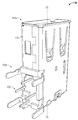
도 3은 실시예에 따른 향상된 안전성 직렬 버스 연결기(100)의 투시도를 도시한다.
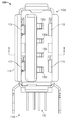
도 4는 향상된 안전성 직렬 버스 연결기(100)의 평면도를 도시한다.
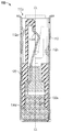
도 5는 도 4에 도시된 섹션 5-5에서 취해진 향상된 안전성 직렬 버스 연결기(100)의 단면도를 도시한다.
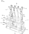
도 6은 향상된 안전성 직렬 버스 연결기(100)의 분해된 투시도를 도시한다.
도 7은 복수의 전도체들(130)을 캡슐화하는 리드 부분(124)을 도시한다.
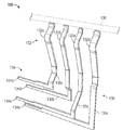
도 8은 절연 바디(120)가 없는 복수의 전도체들(130)을 도시한다.
도 9는 인터페이스에서 간격을 비교하기 위한, 표준 직렬 버스 연결기(10)와 향상된 안전성 직렬 버스 연결기(100)의 인터페이스의 블록 다이어그램을 도시한다.
도 10은 향상된 안전성 직렬 버스 연결기(100)의 평면도를 도시한다.
Claims (18)
- 향상된 안전성 직렬 버스 연결기(100)로서,
제 1 단부(110a) 및 제 2 단부(110b)를 가지는 쉘(shell)(110) ― 상기 제 1 단부(110a)는 상기 쉘(110)의 단자 단부이고 단자 중심라인(CL)을 가지며, 그리고 상기 제 2 단부(110b)는 상기 쉘(110)의 리드(lead) 단부임 ―;
상기 쉘(110) 내부에 배치되고 대략 상기 제 1 단부(110a)로부터 상기 제 2 단부(110b)로 연장되는 절연 바디(120); 및
실질적으로 상기 절연 바디(120) 내에 배치되고 그리고 상기 제 1 단부(110a)로부터 상기 제 2 단부(110b)로 연장되는 복수의 전도체들(130)
을 포함하고,
상기 복수의 전도체들(130)은,
상기 제 1 단부(110a)에 가깝고; 그리고
상기 단자 중심라인(CL)에 실질적으로 평행한 접촉부 중심라인들(X, Y)을 가지는 접촉부들(132)을 가지며;
상기 복수의 전도체들(130) 각각의 전도체(130a-130d)는,
상기 복수의 전도체들(130) 상의 전압을 정의하는 직렬 버스 표준의 간격 요건들에 실질적으로 따르고; 그리고
상기 직렬 버스 표준에 의해 정의된 전압에 대한 최소 향상된 안전성 거리 요건보다 크거나 이와 같은 거리로 인접한 전도체(130a-130d)로부터 이격되는,
향상된 안전성 직렬 버스 연결기(100). - 제 1 항에 있어서,
상기 접촉부 중심라인들(X, Y)은 상기 직렬 버스 표준에서 정의된 대응하는 거리들보다 더 큰 거리들로 상기 단자 중심라인(CL)으로부터 이격되는,
향상된 안전성 직렬 버스 연결기(100). - 제 1 항 또는 제 2 항에 있어서,
상기 복수의 전도체들(130)은 상기 직렬 버스 표준에서 정의된 폭들보다 더 작은 전도체 폭들(WI, WO)로 구성되는,
향상된 안전성 직렬 버스 연결기(100). - 제 1 항 내지 제 3 항 중 어느 한 항에 있어서,
상기 복수의 전도체들(130)은 4개의 전도체들(130a-130d)로 구성되고, 상기 4개의 전도체들(130a-130d)은:
상기 단자 중심라인(CL)으로부터 대략 1.15 mm만큼 이격된 내부 접촉부 중심라인들(X)을 가지는 2개의 내부 전도체들(130a-130b); 및
상기 단자 중심라인(CL)으로부터 대략 3.58 mm만큼 이격된 외부 접촉부 중심라인들(Y)을 가지는 2개의 외부 전도체들(130c-130d)로 구성되는,
향상된 안전성 직렬 버스 연결기(100). - 제 1 항 내지 제 4 항 중 어느 한 항에 있어서,
상기 복수의 전도체들(130)은 4개의 전도체들(130a-130d)로 구성되고, 상기 4개의 전도체들(130a-130d)은:
대략 0.60 mm의 내부 접촉부 폭(WI)을 가지는 2개의 내부 전도체들(130a-130b); 및
대략 0.85 mm의 외부 접촉부 폭(WO)을 가지는 2개의 외부 전도체들(130c-130d)로 구성되는,
향상된 안전성 직렬 버스 연결기(100). - 제 1 항 내지 제 5 항 중 어느 한 항에 있어서,
상기 최소 향상된 안전성 거리 요건은 연면 거리(creepage distance)를 포함하고, 상기 연면 거리는 상기 절연 바디(120)의 표면을 따르는 거리인,
향상된 안전성 직렬 버스 연결기(100). - 제 1 항 내지 제 6 항 중 어느 한 항에 있어서,
상기 복수의 전도체들(130)은:
상기 절연 바디(120)의 표면에 균일하게 분배되고; 그리고
상기 절연 바디(120)의 표면에 실질적으로 수직인 상기 절연 바디(120)의 표면으로부터 연장되는,
향상된 안전성 직렬 버스 연결기(100). - 제 7 항에 있어서,
상기 절연 바디(120)의 표면은 리드 대향 표면(124a)이고 그리고 상기 복수의 전도체들(130)은 상기 리드 대향 표면(124a)에 균일하게 분배되는,
향상된 안전성 직렬 버스 연결기(100). - 제 1 항 내지 제 8 항 중 어느 한 항에 있어서,
상기 직렬 버스 표준은 USB(Universal Serial Bus) 표준인,
향상된 안전성 직렬 버스 연결기(100). - 향상된 안전성 직렬 버스 연결기(100)를 형성하는 방법으로서,
제 1 단부(110a) 및 제 2 단부(110b)로 구성된 쉘(110)을 형성하는 단계 ― 상기 제 1 단부(110a)는 상기 쉘(110)의 단자 단부이고 단자 중심라인(CL)을 가지며, 그리고 상기 제 2 단부(110b)는 상기 쉘(110)의 리드 단부임 ―; 및
복수의 전도체들(130)을 형성하는 단계
를 포함하고,
상기 복수의 전도체들(130) 각각의 전도체(130a-130d)는:
상기 복수의 전도체들(130) 상의 전압을 정의하는 직렬 버스 표준의 간격 요건들에 실질적으로 따르고; 그리고
상기 직렬 버스 표준에 의해 정의된 전압에 대한 최소 향상된 안전성 거리 요건보다 크거나 이와 같은 거리로 인접한 전도체(130a-130d)로부터 이격되는,
향상된 안전성 직렬 버스 연결기(100)를 형성하는 방법. - 제 10 항에 있어서,
상기 복수의 전도체들(130)의 적어도 일부 부근에 절연 바디(120)의 적어도 일부를 형성하는 단계;
상기 절연 바디(120)의 적어도 일부를 상기 쉘(110) 내부에 배치하고 대략 상기 제 1 단부(110a)로부터 상기 제 2 단부(110b)로 연장시키는 단계; 및
접촉부들(132)이,
상기 제 1 단부(110a)에 가깝고; 그리고
상기 단자 중심라인(CL)에 실질적으로 평행한 접촉부 중심라인들(X, Y)을 가지도록 상기 복수의 전도체들(130)을 포지셔닝하는 단계
를 더 포함하는,
향상된 안전성 직렬 버스 연결기(100)를 형성하는 방법. - 제 10 항 또는 제 11 항에 있어서,
상기 절연 바디(120)로 상기 복수의 전도체들(130)을 캡슐화하는 단계를 더 포함하는,
향상된 안전성 직렬 버스 연결기(100)를 형성하는 방법. - 제 12 항에 있어서,
상기 복수의 전도체들(130)을 캡슐화하는 단계는 상기 절연 바디(120)의 표면에 상기 복수의 전도체들(130)을 균일하게 분배하는 단계를 포함하는,
향상된 안전성 직렬 버스 연결기(100)를 형성하는 방법. - 제 12 항에 있어서,
상기 복수의 전도체들(130)을 캡슐화하는 단계는 상기 절연 바디(120)의 표면에 실질적으로 수직인 방향으로 상기 절연 바디(120)의 표면으로부터 상기 복수의 전도체들(130)을 연장시키는 단계를 포함하는,
향상된 안전성 직렬 버스 연결기(100)를 형성하는 방법. - 제 10 항 내지 제 14 항 중 어느 한 항에 있어서,
상기 복수의 전도체들(130)을 형성하는 단계는 상기 복수의 전도체들(130)의 편평한 버전을 형성하는 단계 및 상기 복수의 전도체들(130)을 구부리는 단계를 포함하는,
향상된 안전성 직렬 버스 연결기(100)를 형성하는 방법. - 제 10 항 내지 제 15 항 중 어느 한 항에 있어서,
상기 복수의 전도체들(130)을 형성하는 단계는 상기 직렬 버스 표준에서 특정된 대응하는 폭보다 작은 폭(WI)을 가지는 상기 복수의 전도체들(130) 중 적어도 하나를 형성하는 단계를 포함하는,
향상된 안전성 직렬 버스 연결기(100)를 형성하는 방법. - 제 10 항 내지 제 16 항 중 어느 한 항에 있어서,
상기 복수의 전도체들(130)을 형성하는 단계는 중심라인들(X)을 가지는 상기 복수의 전도체들(130) 중 적어도 2개를 형성하는 단계를 포함하고, 상기 중심라인들(X)과 상기 단자 중심라인(CL) 간의 거리는 상기 직렬 버스 표준에서 특정된 대응하는 거리보다 더 큰,
향상된 안전성 직렬 버스 연결기(100)를 형성하는 방법. - 제 10 항 내지 제 17 항 중 어느 한 항에 있어서,
상기 직렬 버스 표준은 USB(Universal Serial Bus) 표준인,
향상된 안전성 직렬 버스 연결기(100)를 형성하는 방법.
Applications Claiming Priority (1)
| Application Number | Priority Date | Filing Date | Title |
|---|---|---|---|
| PCT/US2014/055010 WO2016039744A1 (en) | 2014-09-10 | 2014-09-10 | An enhanced safety serial bus connector |
Related Child Applications (1)
| Application Number | Title | Priority Date | Filing Date |
|---|---|---|---|
| KR1020187025967A Division KR102100265B1 (ko) | 2014-09-10 | 2014-09-10 | 향상된 안전성 직렬 버스 연결기 |
Publications (1)
| Publication Number | Publication Date |
|---|---|
| KR20170054469A true KR20170054469A (ko) | 2017-05-17 |
Family
ID=51585248
Family Applications (2)
| Application Number | Title | Priority Date | Filing Date |
|---|---|---|---|
| KR1020187025967A Active KR102100265B1 (ko) | 2014-09-10 | 2014-09-10 | 향상된 안전성 직렬 버스 연결기 |
| KR1020177009717A Ceased KR20170054469A (ko) | 2014-09-10 | 2014-09-10 | 향상된 안전성 직렬 버스 연결기 |
Family Applications Before (1)
| Application Number | Title | Priority Date | Filing Date |
|---|---|---|---|
| KR1020187025967A Active KR102100265B1 (ko) | 2014-09-10 | 2014-09-10 | 향상된 안전성 직렬 버스 연결기 |
Country Status (13)
| Country | Link |
|---|---|
| US (1) | US10522955B2 (ko) |
| EP (1) | EP3192133B1 (ko) |
| JP (1) | JP6815991B2 (ko) |
| KR (2) | KR102100265B1 (ko) |
| CN (1) | CN106797092B (ko) |
| AR (1) | AR101784A1 (ko) |
| AU (1) | AU2014405914B2 (ko) |
| BR (1) | BR112017003609B1 (ko) |
| CA (1) | CA2960676C (ko) |
| MX (1) | MX364969B (ko) |
| RU (1) | RU2663888C1 (ko) |
| SG (1) | SG11201701797VA (ko) |
| WO (1) | WO2016039744A1 (ko) |
Families Citing this family (5)
| Publication number | Priority date | Publication date | Assignee | Title |
|---|---|---|---|---|
| US11353868B2 (en) | 2017-04-24 | 2022-06-07 | Intel Corporation | Barriers and synchronization for machine learning at autonomous machines |
| JP7142454B2 (ja) * | 2018-04-13 | 2022-09-27 | Juki株式会社 | 実装装置、実装方法 |
| JP2019071282A (ja) * | 2018-12-20 | 2019-05-09 | マイクロ モーション インコーポレイテッド | 安全性が強化されたシリアルバスコネクタ |
| DE102020104022B3 (de) | 2020-02-17 | 2021-08-12 | Md Elektronik Gmbh | Kurzschlussstift, Steckverbindung mit einem solchen Kurzschlussstift und ein Verfahren zur Herstellung eines solchen Kurzschlussstifts |
| JP7341943B2 (ja) | 2020-04-27 | 2023-09-11 | ヒロセ電機株式会社 | 電気コネクタ |
Family Cites Families (21)
| Publication number | Priority date | Publication date | Assignee | Title |
|---|---|---|---|---|
| US4269470A (en) * | 1979-08-17 | 1981-05-26 | Ustin Martin D | Modular electrical terminal board |
| US8396790B2 (en) | 2002-12-04 | 2013-03-12 | Efficient Finance Ltd. | System and method for financing commercial transactions |
| US7717104B2 (en) | 2005-07-12 | 2010-05-18 | Looft Industries Ab | Handheld device for fast electrical ignition of a charcoal grill |
| EP1961083B1 (en) * | 2005-11-23 | 2016-01-27 | Draeger Medical Systems, Inc. | A connector system |
| US20080017405A1 (en) * | 2006-07-20 | 2008-01-24 | Giga-Byte Technology Co., Ltd. | Circuit board and anti-static module thereof |
| CN101364694B (zh) | 2007-08-10 | 2011-08-10 | 富士康(昆山)电脑接插件有限公司 | 电连接器 |
| CN201113013Y (zh) * | 2007-09-03 | 2008-09-10 | 富士康(昆山)电脑接插件有限公司 | 电连接器 |
| CN101242047B (zh) * | 2008-02-26 | 2010-06-09 | 华为终端有限公司 | Usb连接件及usb装置 |
| CN201204275Y (zh) | 2008-04-09 | 2009-03-04 | 富士康(昆山)电脑接插件有限公司 | 电连接器 |
| US8076580B2 (en) * | 2009-06-08 | 2011-12-13 | CareFusion 209, Inc. | Cable for enhancing biopotential measurements and method of assembling the same |
| RU88855U1 (ru) * | 2009-06-18 | 2009-11-20 | Общество с ограниченной ответственностью "Русская электротехническая компания" ("РУСЭЛКОМ") | Клеммная колодка |
| KR101124668B1 (ko) * | 2010-01-12 | 2012-03-20 | 주식회사 크리어전자 | 사각프레임을 구비한 양방향 플러그 |
| CN201752040U (zh) * | 2010-05-25 | 2011-02-23 | 中兴通讯股份有限公司 | 一种usb连接器 |
| CN102290654B (zh) * | 2010-06-21 | 2014-02-19 | 富士康(昆山)电脑接插件有限公司 | 电连接器 |
| CN102315534B (zh) * | 2010-07-08 | 2014-08-20 | 泰科电子(上海)有限公司 | 电连接器 |
| US8801462B2 (en) * | 2011-05-27 | 2014-08-12 | Chou Hsien Tsai | Electrical socket |
| JP5730132B2 (ja) * | 2011-06-03 | 2015-06-03 | 矢崎総業株式会社 | コネクタユニット |
| US20140055940A1 (en) * | 2012-08-21 | 2014-02-27 | Skymedi Corporation | Memory device |
| US20140066741A1 (en) * | 2012-08-29 | 2014-03-06 | General Electric Company | Disposable ECG Leadwire Connector |
| RU132925U1 (ru) * | 2013-01-10 | 2013-09-27 | Федеральное государственное бюджетное образовательное учреждение высшего профессионального образования "Тольяттинский государственный университет" | Гнездо usb-разъема |
| CN203690546U (zh) * | 2013-03-22 | 2014-07-02 | 诠欣股份有限公司 | 连接器 |
-
2014
- 2014-09-10 KR KR1020187025967A patent/KR102100265B1/ko active Active
- 2014-09-10 WO PCT/US2014/055010 patent/WO2016039744A1/en not_active Ceased
- 2014-09-10 RU RU2017111788A patent/RU2663888C1/ru active
- 2014-09-10 BR BR112017003609-6A patent/BR112017003609B1/pt active IP Right Grant
- 2014-09-10 KR KR1020177009717A patent/KR20170054469A/ko not_active Ceased
- 2014-09-10 CA CA2960676A patent/CA2960676C/en active Active
- 2014-09-10 JP JP2017513415A patent/JP6815991B2/ja active Active
- 2014-09-10 SG SG11201701797VA patent/SG11201701797VA/en unknown
- 2014-09-10 EP EP14771733.4A patent/EP3192133B1/en active Active
- 2014-09-10 AU AU2014405914A patent/AU2014405914B2/en active Active
- 2014-09-10 MX MX2017002647A patent/MX364969B/es active IP Right Grant
- 2014-09-10 US US15/505,424 patent/US10522955B2/en active Active
- 2014-09-10 CN CN201480081870.4A patent/CN106797092B/zh active Active
-
2015
- 2015-09-08 AR ARP150102861A patent/AR101784A1/es active IP Right Grant
Also Published As
| Publication number | Publication date |
|---|---|
| CA2960676C (en) | 2019-08-13 |
| BR112017003609A2 (pt) | 2017-11-28 |
| CN106797092A (zh) | 2017-05-31 |
| MX364969B (es) | 2019-05-16 |
| US10522955B2 (en) | 2019-12-31 |
| WO2016039744A1 (en) | 2016-03-17 |
| AU2014405914B2 (en) | 2018-04-26 |
| RU2663888C1 (ru) | 2018-08-16 |
| KR20180102228A (ko) | 2018-09-14 |
| US20170244204A1 (en) | 2017-08-24 |
| JP6815991B2 (ja) | 2021-01-20 |
| KR102100265B1 (ko) | 2020-04-17 |
| BR112017003609B1 (pt) | 2022-04-26 |
| SG11201701797VA (en) | 2017-04-27 |
| EP3192133A1 (en) | 2017-07-19 |
| AR101784A1 (es) | 2017-01-11 |
| CA2960676A1 (en) | 2016-03-17 |
| AU2014405914A1 (en) | 2017-03-16 |
| MX2017002647A (es) | 2017-05-30 |
| EP3192133B1 (en) | 2024-10-30 |
| JP2017528875A (ja) | 2017-09-28 |
| CN106797092B (zh) | 2021-09-03 |
Similar Documents
| Publication | Publication Date | Title |
|---|---|---|
| US10897097B2 (en) | Electrical connector device | |
| CN104126255B (zh) | 插塞式连接器及由该插塞式连接器构成的同轴连接器 | |
| US7878850B2 (en) | Cable connector assembly with grounding device | |
| US11289854B2 (en) | Electrical connecting device | |
| US9768567B2 (en) | Flippable electrical connector | |
| US20170033506A1 (en) | Electrical connector having good anti-emi perfprmance | |
| CN101183760B (zh) | 电连接器 | |
| US10367294B1 (en) | Electrical device having a ground termination component with strain relief | |
| US6749463B1 (en) | Shielded board mounted electrical connector | |
| US8366491B2 (en) | USB plug cable assembly | |
| CN106935995A (zh) | 板对板连接器总成 | |
| KR102100265B1 (ko) | 향상된 안전성 직렬 버스 연결기 | |
| CN103975489B (zh) | 制造插入型连接器的方法 | |
| US6699074B1 (en) | Cable connector assembly having improved grounding means | |
| CN108808296B (zh) | 插座电连接器 | |
| US6672913B1 (en) | Plug connector and method for manufacturing the same | |
| TWM541135U (zh) | 插座電連接器 | |
| JP6481729B2 (ja) | 電気コネクタ | |
| JP2019071282A (ja) | 安全性が強化されたシリアルバスコネクタ | |
| CN204966899U (zh) | 插座电连接器 | |
| JP2021052009A (ja) | 安全性が強化されたシリアルバスコネクタ | |
| HK1238415A1 (en) | An enhanced safety serial bus connector | |
| EP4697517A1 (en) | Electrical connector for automotive applications | |
| HK1238415B (zh) | 增强安全串行总线连接器 | |
| CN112217059B (zh) | 多极基板电连接器 |
Legal Events
| Date | Code | Title | Description |
|---|---|---|---|
| A201 | Request for examination | ||
| PA0105 | International application |
Patent event date: 20170410 Patent event code: PA01051R01D Comment text: International Patent Application |
|
| PA0201 | Request for examination | ||
| PG1501 | Laying open of application | ||
| E902 | Notification of reason for refusal | ||
| PE0902 | Notice of grounds for rejection |
Comment text: Notification of reason for refusal Patent event date: 20180405 Patent event code: PE09021S01D |
|
| E601 | Decision to refuse application | ||
| PE0601 | Decision on rejection of patent |
Patent event date: 20180807 Comment text: Decision to Refuse Application Patent event code: PE06012S01D Patent event date: 20180405 Comment text: Notification of reason for refusal Patent event code: PE06011S01I |
|
| A107 | Divisional application of patent | ||
| J201 | Request for trial against refusal decision | ||
| PA0104 | Divisional application for international application |
Comment text: Divisional Application for International Patent Patent event code: PA01041R01D Patent event date: 20180907 |
|
| PJ0201 | Trial against decision of rejection |
Patent event date: 20180907 Comment text: Request for Trial against Decision on Refusal Patent event code: PJ02012R01D Patent event date: 20180807 Comment text: Decision to Refuse Application Patent event code: PJ02011S01I Appeal kind category: Appeal against decision to decline refusal Decision date: 20190925 Appeal identifier: 2018101003741 Request date: 20180907 |
|
| J301 | Trial decision |
Free format text: TRIAL NUMBER: 2018101003741; TRIAL DECISION FOR APPEAL AGAINST DECISION TO DECLINE REFUSAL REQUESTED 20180907 Effective date: 20190925 |
|
| PJ1301 | Trial decision |
Patent event code: PJ13011S01D Patent event date: 20190925 Comment text: Trial Decision on Objection to Decision on Refusal Appeal kind category: Appeal against decision to decline refusal Request date: 20180907 Decision date: 20190925 Appeal identifier: 2018101003741 |
|
| J121 | Written withdrawal of request for trial | ||
| PC1202 | Submission of document of withdrawal before decision of registration |
Comment text: [Withdrawal of Procedure relating to Patent, etc.] Withdrawal (Abandonment) Patent event code: PC12021R01D Patent event date: 20191118 |
|
| PJ1201 | Withdrawal of trial |
Patent event code: PJ12011R01D Patent event date: 20191118 Comment text: Written Withdrawal of Request for Trial Appeal identifier: 2018101003741 Request date: 20180907 Appeal kind category: Appeal against decision to decline refusal Decision date: 20190925 |
|
| WITB | Written withdrawal of application |