KR20170054893A - 회전체의 이상 작동 진단 장치 - Google Patents
회전체의 이상 작동 진단 장치 Download PDFInfo
- Publication number
- KR20170054893A KR20170054893A KR1020150157608A KR20150157608A KR20170054893A KR 20170054893 A KR20170054893 A KR 20170054893A KR 1020150157608 A KR1020150157608 A KR 1020150157608A KR 20150157608 A KR20150157608 A KR 20150157608A KR 20170054893 A KR20170054893 A KR 20170054893A
- Authority
- KR
- South Korea
- Prior art keywords
- vibration
- rotating body
- generated
- shaft
- sensor
- Prior art date
- Legal status (The legal status is an assumption and is not a legal conclusion. Google has not performed a legal analysis and makes no representation as to the accuracy of the status listed.)
- Granted
Links
Images


Classifications
-
- G—PHYSICS
- G01—MEASURING; TESTING
- G01M—TESTING STATIC OR DYNAMIC BALANCE OF MACHINES OR STRUCTURES; TESTING OF STRUCTURES OR APPARATUS, NOT OTHERWISE PROVIDED FOR
- G01M13/00—Testing of machine parts
-
- G—PHYSICS
- G01—MEASURING; TESTING
- G01M—TESTING STATIC OR DYNAMIC BALANCE OF MACHINES OR STRUCTURES; TESTING OF STRUCTURES OR APPARATUS, NOT OTHERWISE PROVIDED FOR
- G01M1/00—Testing static or dynamic balance of machines or structures
- G01M1/14—Determining imbalance
- G01M1/16—Determining imbalance by oscillating or rotating the body to be tested
- G01M1/22—Determining imbalance by oscillating or rotating the body to be tested and converting vibrations due to imbalance into electric variables
-
- F—MECHANICAL ENGINEERING; LIGHTING; HEATING; WEAPONS; BLASTING
- F03—MACHINES OR ENGINES FOR LIQUIDS; WIND, SPRING, OR WEIGHT MOTORS; PRODUCING MECHANICAL POWER OR A REACTIVE PROPULSIVE THRUST, NOT OTHERWISE PROVIDED FOR
- F03D—WIND MOTORS
- F03D17/00—Monitoring or testing of wind motors, e.g. diagnostics
-
- G—PHYSICS
- G01—MEASURING; TESTING
- G01H—MEASUREMENT OF MECHANICAL VIBRATIONS OR ULTRASONIC, SONIC OR INFRASONIC WAVES
- G01H1/00—Measuring characteristics of vibrations in solids by using direct conduction to the detector
- G01H1/003—Measuring characteristics of vibrations in solids by using direct conduction to the detector of rotating machines
-
- G—PHYSICS
- G01—MEASURING; TESTING
- G01H—MEASUREMENT OF MECHANICAL VIBRATIONS OR ULTRASONIC, SONIC OR INFRASONIC WAVES
- G01H11/00—Measuring mechanical vibrations or ultrasonic, sonic or infrasonic waves by detecting changes in electric or magnetic properties
- G01H11/06—Measuring mechanical vibrations or ultrasonic, sonic or infrasonic waves by detecting changes in electric or magnetic properties by electric means
-
- G—PHYSICS
- G01—MEASURING; TESTING
- G01M—TESTING STATIC OR DYNAMIC BALANCE OF MACHINES OR STRUCTURES; TESTING OF STRUCTURES OR APPARATUS, NOT OTHERWISE PROVIDED FOR
- G01M13/00—Testing of machine parts
- G01M13/02—Gearings; Transmission mechanisms
- G01M13/028—Acoustic or vibration analysis
-
- H—ELECTRICITY
- H02—GENERATION; CONVERSION OR DISTRIBUTION OF ELECTRIC POWER
- H02K—DYNAMO-ELECTRIC MACHINES
- H02K11/00—Structural association of dynamo-electric machines with electric components or with devices for shielding, monitoring or protection
- H02K11/20—Structural association of dynamo-electric machines with electric components or with devices for shielding, monitoring or protection for measuring, monitoring, testing, protecting or switching
Landscapes
- Physics & Mathematics (AREA)
- General Physics & Mathematics (AREA)
- Acoustics & Sound (AREA)
- Engineering & Computer Science (AREA)
- Testing Of Devices, Machine Parts, Or Other Structures Thereof (AREA)
- Measurement Of Mechanical Vibrations Or Ultrasonic Waves (AREA)
- Power Engineering (AREA)
- Life Sciences & Earth Sciences (AREA)
- Sustainable Development (AREA)
- Sustainable Energy (AREA)
- Chemical & Material Sciences (AREA)
- Combustion & Propulsion (AREA)
- Mechanical Engineering (AREA)
- General Engineering & Computer Science (AREA)
- Microelectronics & Electronic Packaging (AREA)
Abstract
Description
도 2는 본 발명의 일 실시 예에 따른 회전체의 이상 작동 진단 장치에 구비된 진동 센서와 타코 센서 및 진동 센서와 타코 센서의 조합된 상태를 도시한 도면.
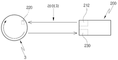
도 3은 본 발명의 일 실시 예에 따른 회전체의 이상 작동 진단 장치에 구비된 제2 센서의 구성을 도시한 도면.
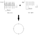
도 4는 본 발명의 일 실시 예에 따른 회전체의 이상 작동 진단 장치에서 이상 진동이 발생된 상태를 도시한 도면.
도 5는 본 발명의 일 실시 예에 따른 표시부의 설치 위치를 간략히 도시한 도면.
도 6은 본 발명의 일 실시 예에 의한 이상 작동 상태 진단 방법을 도시한 순서도.
3 : 샤프트
100 : 제1 센서
200 : 제2 센서
210 : 본체부
212 : 발광부
220 : 반사판
230 : 수광부
300 : 제어부
400 : 표시부
Claims (12)
- 회전체에 구비된 샤프트가 축 방향에서 회전되면서 발생되는 진동을 감지하기 위해 상기 샤프트 주위에 구비된 제1 센서;
상기 샤프트가 1회전 할 때마다 시간에 따른 주기성 펄스 신호를 생성하는 제2 센서;
상기 제1,2 센서에서 감지된 신호를 입력 받아 상기 회전체의 작동 상태를 판단하고, 상기 회전체에서 비 주기성 펄스 신호가 감지될 경우 상기 비 주기성 펄스 신호가 발생된 회전체의 위치를 판단하는 제어부; 및
상기 제어부에서 연산된 정보에 따라 상기 회전체의 비 주기성 펄스 신호가 발생된 위치가 표시되는 표시부를 포함하는 회전체의 이상 작동 진단 장치. - 제1 항에 있어서,
상기 제1 센서는 진동 센서가 사용되고, 상기 제2 센서는 타코 센서가 사용되는 회전체의 이상 작동 진단 장치. - 제1에 있어서,
상기 제1 센서는,
상기 샤프트를 지지하는 베어링 마운트에 위치되는 회전체의 이상 작동 진단 장치. - 제2 항에 있어서,
상기 제2 센서는,
상기 샤프트를 향해 레이저를 조사하는 발광부가 구비된 본체부;
상기 샤프트와 함께 회전되고 상기 발광부에서 조사된 레이저를 상기 본체부로 반사하는 반사판;
상기 본체부에 구비되고 상기 반사판에서 반사된 레이저를 수신하는 수광부를 포함하는 회전체의 이상 작동 진단 장치. - 제2 항에 있어서,
상기 제2 센서는,
상기 제1 센서와 서로 마주보는 위치에 설치되거나, 상기 제1 센서와 소정의 각도로 이격된 위치 중의 어느 하나의 위치에 선택적으로 설치되는 회전체의 이상 작동 진단 장치. - 제1 항에 있어서,
상기 표시부는,
상기 회전체의 외측 원주 방향을 따라 등 간격으로 배치된 다수개의 발광소자로 이루어진 것을 특징으로 하는 회전체의 이상 작동 진단 장치. - 제1 항에 있어서,
상기 표시부는,
상기 회전체의 외측 축 방향을 따라 등 간격으로 배치된 다수개의 발광소자로 이루어진 것을 특징으로 하는 회전체의 이상 작동 진단 장치. - 샤프트가 구비된 회전체에서 발생되는 진동을 감지하는 단계;
상기 감지된 진동이 정상 상태에서 발생된 진동인지 비 정상 상태에서 발생된 진동인지 판단하는 진동 상태 판단 단계;
상기 회전체에서 발생된 진동이 비 정상 상태에서 발생된 이상 진동인 것으로 판단될 경우 상기 이상 진동이 발생된 위치를 판단하는 단계; 및
상기 이상 진동이 발생된 위치가 표시되는 단계를 포함하는 회전체의 이상 작동 상태 진단 방법. - 제8 항에 있어서,
상기 진동을 감지하는 단계는,
상기 회전체에 구비된 샤프트가 1회전 하면서 반복적으로 발생되는 주기성 진동과, 상기 회전체에 구비된 샤프트가 1회전 하면서 비 반복적으로 발생되는 비 주기성 진동을 동시에 감지하는 것을 특징으로 하는 회전체의 이상 작동 상태 진단 방법. - 제8 항에 있어서,
상기 진동 상태 판단 단계는,
상기 샤프트가 축 방향에서 회전되면서 일정 주기로 진동이 발생될 경우 정상 상태에서 발생된 진동으로 판단하고,
상기 샤프트가 축 방향에서 회전되면서 비 주기적으로 진동이 발생될 경우 비 정상 상태에서 발생된 진동으로 판단하는 회전체의 이상 작동 상태 진단 방법. - 제8 항에 있어서,
상기 이상 진동이 발생된 위치를 판단하는 단계는,
상기 샤프트가 회전하면서 시간에 따라 발생된 주기성 진동 신호들 사이에서 감지된 비 주기성 진동 신호가 발생된 시간을 각도로 환산하여 상기 이상 진동이 발생된 위치를 판단하는 것을 특징으로 하는 회전체의 이상 작동 상태 진단 방법. - 제8 항에 있어서,
상기 이상 진동이 발생된 위치를 표시하는 단계는,
상기 회전체가 샤프트의 축 방향을 따라 소정의 길이로 연장된 원통 형태일 경우 상기 회전체 선단부의 원주 방향을 따라 등 간격으로 배치된 다수개의 발광소자 중에서 비 주기성 진동이 발생된 위치에 해당되는 어느 하나의 발광소자를 점등시켜 위치를 표시하는 회전체의 이상 작동 상태 진단 방법.
Priority Applications (3)
| Application Number | Priority Date | Filing Date | Title |
|---|---|---|---|
| KR1020150157608A KR101761022B1 (ko) | 2015-11-10 | 2015-11-10 | 회전체의 이상 작동 진단 장치 |
| EP16197940.6A EP3168583B1 (en) | 2015-11-10 | 2016-11-09 | Apparatus and method for diagnosing abnormal operation of a rotor |
| US15/348,267 US10481034B2 (en) | 2015-11-10 | 2016-11-10 | Apparatus and method for diagnosing abnormal operation of a rotor |
Applications Claiming Priority (1)
| Application Number | Priority Date | Filing Date | Title |
|---|---|---|---|
| KR1020150157608A KR101761022B1 (ko) | 2015-11-10 | 2015-11-10 | 회전체의 이상 작동 진단 장치 |
Publications (2)
| Publication Number | Publication Date |
|---|---|
| KR20170054893A true KR20170054893A (ko) | 2017-05-18 |
| KR101761022B1 KR101761022B1 (ko) | 2017-07-24 |
Family
ID=57281093
Family Applications (1)
| Application Number | Title | Priority Date | Filing Date |
|---|---|---|---|
| KR1020150157608A Active KR101761022B1 (ko) | 2015-11-10 | 2015-11-10 | 회전체의 이상 작동 진단 장치 |
Country Status (3)
| Country | Link |
|---|---|
| US (1) | US10481034B2 (ko) |
| EP (1) | EP3168583B1 (ko) |
| KR (1) | KR101761022B1 (ko) |
Cited By (2)
| Publication number | Priority date | Publication date | Assignee | Title |
|---|---|---|---|---|
| KR20180127693A (ko) * | 2017-05-22 | 2018-11-30 | 정경균 | 수직형 풍력발전기 |
| KR20230089926A (ko) * | 2021-12-14 | 2023-06-21 | 한국표준과학연구원 | D-norm 기반 시간 동기 평균 기법에 의한 회전체 고장 진단 시스템 및 방법 |
Families Citing this family (8)
| Publication number | Priority date | Publication date | Assignee | Title |
|---|---|---|---|---|
| US11016003B2 (en) | 2016-11-17 | 2021-05-25 | Ez Pulley Llc | Systems and methods for detection and analysis of faulty components in a rotating pulley system |
| CN107643549B (zh) * | 2017-10-13 | 2024-03-01 | 国能大渡河流域水电开发有限公司龚嘴水力发电总厂 | 非接触式发电机组气隙异物在线检测报警结构及报警方法 |
| CN108827539B (zh) * | 2018-03-30 | 2020-02-21 | 江苏大学 | 一种多转子装配在线动平衡试验装置 |
| CN109580217B (zh) * | 2018-09-27 | 2020-08-14 | 中北大学 | 一种风电齿轮箱的故障监测方法 |
| DE102019127211A1 (de) * | 2019-03-05 | 2020-09-10 | Computational Systems, Inc. | System zum Trennen von periodischen Amplitudenspitzen von nicht-periodischen Amplitudenspitzen in Maschinenschwingungsdaten |
| JP2022100163A (ja) * | 2020-12-23 | 2022-07-05 | トヨタ自動車株式会社 | 音源推定サーバ、音源推定システム、音源推定装置、音源推定方法 |
| US20220373422A1 (en) * | 2021-05-20 | 2022-11-24 | Machine Saver, Inc. | Vibration detection and correction system |
| US11781782B2 (en) | 2021-06-23 | 2023-10-10 | Carrier Corporation | Indication of motor shaft rotation and controller location |
Family Cites Families (9)
| Publication number | Priority date | Publication date | Assignee | Title |
|---|---|---|---|---|
| US2090803A (en) * | 1933-07-13 | 1937-08-24 | Harry W Moore | Dynamic balancing apparatus |
| US4238960A (en) | 1978-11-27 | 1980-12-16 | Lockheed Corporation | Means for balancing rotors of a machine |
| US4335600A (en) * | 1980-11-13 | 1982-06-22 | General Electric Company | Detecting internal abnormalities in turbines |
| JPS5834363A (ja) | 1981-08-25 | 1983-02-28 | Yokogawa Hokushin Electric Corp | 回転計 |
| JPH08334405A (ja) | 1995-06-08 | 1996-12-17 | Omron Corp | 回転機の異常診断装置 |
| US6098022A (en) * | 1997-10-17 | 2000-08-01 | Test Devices, Inc. | Detecting anomalies in rotating components |
| JP2009281839A (ja) * | 2008-05-22 | 2009-12-03 | Sanyo Special Steel Co Ltd | 金属製棒材の表面疵検査方法 |
| US8042412B2 (en) * | 2008-06-25 | 2011-10-25 | General Electric Company | Turbomachinery system fiberoptic multi-parameter sensing system and method |
| US8478548B2 (en) * | 2010-01-15 | 2013-07-02 | Fluke Corporation | User interface system and method for diagnosing a rotating machine condition not based upon prior measurement history |
-
2015
- 2015-11-10 KR KR1020150157608A patent/KR101761022B1/ko active Active
-
2016
- 2016-11-09 EP EP16197940.6A patent/EP3168583B1/en active Active
- 2016-11-10 US US15/348,267 patent/US10481034B2/en active Active
Cited By (2)
| Publication number | Priority date | Publication date | Assignee | Title |
|---|---|---|---|---|
| KR20180127693A (ko) * | 2017-05-22 | 2018-11-30 | 정경균 | 수직형 풍력발전기 |
| KR20230089926A (ko) * | 2021-12-14 | 2023-06-21 | 한국표준과학연구원 | D-norm 기반 시간 동기 평균 기법에 의한 회전체 고장 진단 시스템 및 방법 |
Also Published As
| Publication number | Publication date |
|---|---|
| KR101761022B1 (ko) | 2017-07-24 |
| US20170131172A1 (en) | 2017-05-11 |
| EP3168583B1 (en) | 2021-01-13 |
| US10481034B2 (en) | 2019-11-19 |
| EP3168583A1 (en) | 2017-05-17 |
Similar Documents
| Publication | Publication Date | Title |
|---|---|---|
| KR101761022B1 (ko) | 회전체의 이상 작동 진단 장치 | |
| EP1419340B1 (en) | Presence sensing system and method | |
| US7231303B2 (en) | Vibration sensor and method for monitoring the condition of rotating components and bearings | |
| CN102607630B (zh) | 编码器的故障检测方法、装置和系统 | |
| US9400229B2 (en) | Apparatus and method for monitoring the state of a roller bearing | |
| EP1906154B1 (en) | Circuit for emulating encoder data | |
| US10487683B2 (en) | System for detecting an ephemeral event on a vane impeller of an aircraft engine | |
| CN101473185A (zh) | 具有内置式自测试的旋转编码器 | |
| KR20130046858A (ko) | 풍력 발전기 블레이드 감시 시스템 및 이를 이용한 감시 방법 | |
| KR102126373B1 (ko) | 회전 장치의 적어도 하나의 가동부에서의 결함 발생 감지 및 모니터링 방법과 관련 시스템 | |
| US20190265097A1 (en) | Method and device for the functional testing of a fibre-optic sensor and computer program product | |
| KR101987466B1 (ko) | 엔코더의 수명시험장치 | |
| CN101473312A (zh) | 旋转编码器频率分析 | |
| CN102261890B (zh) | 回转角度测量装置 | |
| KR101879385B1 (ko) | 진동 감시 설비용 신호 처리 장치 | |
| CN102648417A (zh) | 非侵入式转速传感器 | |
| JP2019007735A (ja) | センサ付きボルトおよびボルト異常検出システム | |
| KR200455910Y1 (ko) | 터빈 발전기의 진동감시설비용 tdm 신호 처리 장치 | |
| JP2019027782A (ja) | トルク検出用モジュール、駆動装置、ステージ装置、ロボット装置、及び制御装置 | |
| KR20110089910A (ko) | 진동모니터 | |
| EP4303679A1 (en) | A system for reviewing an abnormal operating state of an equipment or an apparatus | |
| KR100350880B1 (ko) | 타이어의 밸런스 검사장치 | |
| CN119797124A (zh) | 检测方法、自动扶梯监测系统和自动扶梯 | |
| KR20220067098A (ko) | 자동차용 변속기 진단 시스템 | |
| WO2024106282A1 (ja) | 摩耗検査装置と船舶 |
Legal Events
| Date | Code | Title | Description |
|---|---|---|---|
| A201 | Request for examination | ||
| PA0109 | Patent application |
Patent event code: PA01091R01D Comment text: Patent Application Patent event date: 20151110 |
|
| PA0201 | Request for examination | ||
| PE0902 | Notice of grounds for rejection |
Comment text: Notification of reason for refusal Patent event date: 20161024 Patent event code: PE09021S01D |
|
| PE0701 | Decision of registration |
Patent event code: PE07011S01D Comment text: Decision to Grant Registration Patent event date: 20170419 |
|
| PG1501 | Laying open of application | ||
| GRNT | Written decision to grant | ||
| PR0701 | Registration of establishment |
Comment text: Registration of Establishment Patent event date: 20170718 Patent event code: PR07011E01D |
|
| PR1002 | Payment of registration fee |
Payment date: 20170718 End annual number: 3 Start annual number: 1 |
|
| PG1601 | Publication of registration | ||
| PR1001 | Payment of annual fee |
Payment date: 20200701 Start annual number: 4 End annual number: 4 |
|
| PR1001 | Payment of annual fee |
Payment date: 20210630 Start annual number: 5 End annual number: 5 |
|
| PR1001 | Payment of annual fee |
Payment date: 20220629 Start annual number: 6 End annual number: 6 |
|
| PR1001 | Payment of annual fee |
Payment date: 20230628 Start annual number: 7 End annual number: 7 |
|
| PR1001 | Payment of annual fee |
Payment date: 20240625 Start annual number: 8 End annual number: 8 |
|
| PR1001 | Payment of annual fee |
Payment date: 20250625 Start annual number: 9 End annual number: 9 |