KR20170056570A - Indoor position location using delayed scanned directional reflectors - Google Patents
Indoor position location using delayed scanned directional reflectors Download PDFInfo
- Publication number
- KR20170056570A KR20170056570A KR1020177008232A KR20177008232A KR20170056570A KR 20170056570 A KR20170056570 A KR 20170056570A KR 1020177008232 A KR1020177008232 A KR 1020177008232A KR 20177008232 A KR20177008232 A KR 20177008232A KR 20170056570 A KR20170056570 A KR 20170056570A
- Authority
- KR
- South Korea
- Prior art keywords
- reflector
- delay
- signal
- mobile
- frequency
- Prior art date
- Legal status (The legal status is an assumption and is not a legal conclusion. Google has not performed a legal analysis and makes no representation as to the accuracy of the status listed.)
- Granted
Links
Images









Classifications
-
- G—PHYSICS
- G01—MEASURING; TESTING
- G01S—RADIO DIRECTION-FINDING; RADIO NAVIGATION; DETERMINING DISTANCE OR VELOCITY BY USE OF RADIO WAVES; LOCATING OR PRESENCE-DETECTING BY USE OF THE REFLECTION OR RERADIATION OF RADIO WAVES; ANALOGOUS ARRANGEMENTS USING OTHER WAVES
- G01S13/00—Systems using the reflection or reradiation of radio waves, e.g. radar systems; Analogous systems using reflection or reradiation of waves whose nature or wavelength is irrelevant or unspecified
- G01S13/02—Systems using reflection of radio waves, e.g. primary radar systems; Analogous systems
- G01S13/06—Systems determining position data of a target
- G01S13/42—Simultaneous measurement of distance and other co-ordinates
- G01S13/426—Scanning radar, e.g. 3D radar
-
- G—PHYSICS
- G01—MEASURING; TESTING
- G01C—MEASURING DISTANCES, LEVELS OR BEARINGS; SURVEYING; NAVIGATION; GYROSCOPIC INSTRUMENTS; PHOTOGRAMMETRY OR VIDEOGRAMMETRY
- G01C21/00—Navigation; Navigational instruments not provided for in groups G01C1/00 - G01C19/00
- G01C21/20—Instruments for performing navigational calculations
- G01C21/206—Instruments for performing navigational calculations specially adapted for indoor navigation
-
- G—PHYSICS
- G01—MEASURING; TESTING
- G01S—RADIO DIRECTION-FINDING; RADIO NAVIGATION; DETERMINING DISTANCE OR VELOCITY BY USE OF RADIO WAVES; LOCATING OR PRESENCE-DETECTING BY USE OF THE REFLECTION OR RERADIATION OF RADIO WAVES; ANALOGOUS ARRANGEMENTS USING OTHER WAVES
- G01S13/00—Systems using the reflection or reradiation of radio waves, e.g. radar systems; Analogous systems using reflection or reradiation of waves whose nature or wavelength is irrelevant or unspecified
- G01S13/74—Systems using reradiation of radio waves, e.g. secondary radar systems; Analogous systems
- G01S13/75—Systems using reradiation of radio waves, e.g. secondary radar systems; Analogous systems using transponders powered from received waves, e.g. using passive transponders, or using passive reflectors
- G01S13/751—Systems using reradiation of radio waves, e.g. secondary radar systems; Analogous systems using transponders powered from received waves, e.g. using passive transponders, or using passive reflectors wherein the responder or reflector radiates a coded signal
- G01S13/753—Systems using reradiation of radio waves, e.g. secondary radar systems; Analogous systems using transponders powered from received waves, e.g. using passive transponders, or using passive reflectors wherein the responder or reflector radiates a coded signal using frequency selective elements, e.g. resonator
-
- G—PHYSICS
- G01—MEASURING; TESTING
- G01S—RADIO DIRECTION-FINDING; RADIO NAVIGATION; DETERMINING DISTANCE OR VELOCITY BY USE OF RADIO WAVES; LOCATING OR PRESENCE-DETECTING BY USE OF THE REFLECTION OR RERADIATION OF RADIO WAVES; ANALOGOUS ARRANGEMENTS USING OTHER WAVES
- G01S13/00—Systems using the reflection or reradiation of radio waves, e.g. radar systems; Analogous systems using reflection or reradiation of waves whose nature or wavelength is irrelevant or unspecified
- G01S13/74—Systems using reradiation of radio waves, e.g. secondary radar systems; Analogous systems
- G01S13/75—Systems using reradiation of radio waves, e.g. secondary radar systems; Analogous systems using transponders powered from received waves, e.g. using passive transponders, or using passive reflectors
- G01S13/751—Systems using reradiation of radio waves, e.g. secondary radar systems; Analogous systems using transponders powered from received waves, e.g. using passive transponders, or using passive reflectors wherein the responder or reflector radiates a coded signal
- G01S13/755—Systems using reradiation of radio waves, e.g. secondary radar systems; Analogous systems using transponders powered from received waves, e.g. using passive transponders, or using passive reflectors wherein the responder or reflector radiates a coded signal using delay lines, e.g. acoustic delay lines
-
- G—PHYSICS
- G01—MEASURING; TESTING
- G01S—RADIO DIRECTION-FINDING; RADIO NAVIGATION; DETERMINING DISTANCE OR VELOCITY BY USE OF RADIO WAVES; LOCATING OR PRESENCE-DETECTING BY USE OF THE REFLECTION OR RERADIATION OF RADIO WAVES; ANALOGOUS ARRANGEMENTS USING OTHER WAVES
- G01S13/00—Systems using the reflection or reradiation of radio waves, e.g. radar systems; Analogous systems using reflection or reradiation of waves whose nature or wavelength is irrelevant or unspecified
- G01S13/74—Systems using reradiation of radio waves, e.g. secondary radar systems; Analogous systems
- G01S13/75—Systems using reradiation of radio waves, e.g. secondary radar systems; Analogous systems using transponders powered from received waves, e.g. using passive transponders, or using passive reflectors
- G01S13/751—Systems using reradiation of radio waves, e.g. secondary radar systems; Analogous systems using transponders powered from received waves, e.g. using passive transponders, or using passive reflectors wherein the responder or reflector radiates a coded signal
- G01S13/756—Systems using reradiation of radio waves, e.g. secondary radar systems; Analogous systems using transponders powered from received waves, e.g. using passive transponders, or using passive reflectors wherein the responder or reflector radiates a coded signal using a signal generator for modifying the reflectivity of the reflector
-
- G—PHYSICS
- G01—MEASURING; TESTING
- G01S—RADIO DIRECTION-FINDING; RADIO NAVIGATION; DETERMINING DISTANCE OR VELOCITY BY USE OF RADIO WAVES; LOCATING OR PRESENCE-DETECTING BY USE OF THE REFLECTION OR RERADIATION OF RADIO WAVES; ANALOGOUS ARRANGEMENTS USING OTHER WAVES
- G01S13/00—Systems using the reflection or reradiation of radio waves, e.g. radar systems; Analogous systems using reflection or reradiation of waves whose nature or wavelength is irrelevant or unspecified
- G01S13/74—Systems using reradiation of radio waves, e.g. secondary radar systems; Analogous systems
- G01S13/75—Systems using reradiation of radio waves, e.g. secondary radar systems; Analogous systems using transponders powered from received waves, e.g. using passive transponders, or using passive reflectors
- G01S13/751—Systems using reradiation of radio waves, e.g. secondary radar systems; Analogous systems using transponders powered from received waves, e.g. using passive transponders, or using passive reflectors wherein the responder or reflector radiates a coded signal
- G01S13/758—Systems using reradiation of radio waves, e.g. secondary radar systems; Analogous systems using transponders powered from received waves, e.g. using passive transponders, or using passive reflectors wherein the responder or reflector radiates a coded signal using a signal generator powered by the interrogation signal
-
- G—PHYSICS
- G01—MEASURING; TESTING
- G01S—RADIO DIRECTION-FINDING; RADIO NAVIGATION; DETERMINING DISTANCE OR VELOCITY BY USE OF RADIO WAVES; LOCATING OR PRESENCE-DETECTING BY USE OF THE REFLECTION OR RERADIATION OF RADIO WAVES; ANALOGOUS ARRANGEMENTS USING OTHER WAVES
- G01S13/00—Systems using the reflection or reradiation of radio waves, e.g. radar systems; Analogous systems using reflection or reradiation of waves whose nature or wavelength is irrelevant or unspecified
- G01S13/86—Combinations of radar systems with non-radar systems, e.g. sonar, direction finder
- G01S13/867—Combination of radar systems with cameras
-
- G—PHYSICS
- G01—MEASURING; TESTING
- G01S—RADIO DIRECTION-FINDING; RADIO NAVIGATION; DETERMINING DISTANCE OR VELOCITY BY USE OF RADIO WAVES; LOCATING OR PRESENCE-DETECTING BY USE OF THE REFLECTION OR RERADIATION OF RADIO WAVES; ANALOGOUS ARRANGEMENTS USING OTHER WAVES
- G01S13/00—Systems using the reflection or reradiation of radio waves, e.g. radar systems; Analogous systems using reflection or reradiation of waves whose nature or wavelength is irrelevant or unspecified
- G01S13/87—Combinations of radar systems, e.g. primary radar and secondary radar
- G01S13/876—Combination of several spaced transponders or reflectors of known location for determining the position of a receiver
-
- H—ELECTRICITY
- H01—ELECTRIC ELEMENTS
- H01Q—ANTENNAS, i.e. RADIO AERIALS
- H01Q15/00—Devices for reflection, refraction, diffraction or polarisation of waves radiated from an antenna, e.g. quasi-optical devices
- H01Q15/14—Reflecting surfaces; Equivalent structures
-
- H—ELECTRICITY
- H01—ELECTRIC ELEMENTS
- H01Q—ANTENNAS, i.e. RADIO AERIALS
- H01Q15/00—Devices for reflection, refraction, diffraction or polarisation of waves radiated from an antenna, e.g. quasi-optical devices
- H01Q15/14—Reflecting surfaces; Equivalent structures
- H01Q15/18—Reflecting surfaces; Equivalent structures comprising plurality of mutually inclined plane surfaces, e.g. corner reflector
Landscapes
- Engineering & Computer Science (AREA)
- Radar, Positioning & Navigation (AREA)
- Remote Sensing (AREA)
- Physics & Mathematics (AREA)
- General Physics & Mathematics (AREA)
- Computer Networks & Wireless Communication (AREA)
- Electromagnetism (AREA)
- Automation & Control Theory (AREA)
- Radar Systems Or Details Thereof (AREA)
- Position Fixing By Use Of Radio Waves (AREA)
- Aerials With Secondary Devices (AREA)
- Variable-Direction Aerials And Aerial Arrays (AREA)
Abstract
모바일 디바이스는 위치 반사기까지의 레인지는 물론 반사기에서의 방위 및 고도 도래각(AOA) 또한 측정함으로써 그 위치를 정확하게 결정한다. 모바일은 코딩된 레이더 신호를 송신하고 반사를 프로세싱하여 그 위치를 결정할 수 있다. 반사기는 모바일에 송신/수신 분리를 제공하고 그리고 반사기를 식별시킬 수 있는 내부 지연을 포함할 수 있다. 반사는 일차 및 더 지연된 이차 반사를 포함할 수 있다. 모바일은 일차 반사와 이차 반사 간 지연에 기반하여 반사기의 내부 지연을 결정할 수 있다. 레인지 및 AOA 정보는 위치를 결정하도록 반사기의 위치, 정향, 및 특성에 대한 정보와 조합될 수 있다. 일부 시스템에서, 모바일 디바이스는 단 하나의 반사기로부터의 반사를 사용하여 3-차원 공간에서 그 위치를 결정할 수 있다. 경제적으로 생산될 수 있는 반사기는 용이한 설치를 위해 낮은 프로파일이고 전력을 공급받지 않을 수 있다.The mobile device accurately determines its position by measuring not only the range to the position reflector, but also the azimuth and elevation angle (AOA) at the reflector. The mobile can transmit the coded radar signal and process the reflection to determine its position. The reflector may include an internal delay that provides transmit / receive isolation for the mobile and may identify the reflector. Reflections may include primary and further delayed secondary reflections. The mobile can determine the internal delay of the reflector based on the delay between the primary reflection and the secondary reflection. The range and AOA information may be combined with information about the location, orientation, and characteristics of the reflector to determine the location. In some systems, the mobile device can use its reflection from only one reflector to determine its position in three-dimensional space. Economically produced reflectors are low profile and can be powered off for easy installation.
Description
본 발명은 일반적으로는 위치결정(positioning) 분야에 관한 것이고, 구체적으로는, 실내 측위(indoor location positioning)에 적합한 시스템 및 방법에 관한 것이다.The present invention relates generally to the field of positioning and, in particular, to systems and methods suitable for indoor location positioning.
실내 위치 측위는 오늘날의 모바일 무선 디바이스 환경에서 점점 중요하게 되고 있다. 실외 측위 서비스가 기술이 이용가능하게 된 후 널리 보급되게 되는데 시간이 다소 걸린 반면, 오늘날 실내 위치 측위를 위한 애플리케이션은 이용가능한 기술적 솔루션보다 앞서 경주하고 있다. 많은 기술이 실외 위치 측위에 사용되어 왔고, 그것들 중 으뜸은 수신기가 그 위치를 정확하게 계산하는 것을 가능하게 하는 타이밍 및 레인징 신호를 송신하는 궤도 위성을 사용하는 세계 위치결정 시스템(GPS)이다. GPS에 부가하여, 셀룰러 기지국 삼각측량 및 삼변측량을 포함하여 다양한 채택도를 갖는 여러 다른 기술이 제안되어 왔다.Indoor location positioning is becoming increasingly important in today's mobile wireless device environments. While outdoor positioning services have taken some time to become popular after technology becomes available, today's applications for indoor location positioning are ahead of the available technical solutions. A number of techniques have been used for outdoor position locating, the chief of which is the Global Positioning System (GPS), which uses an orbiting satellite to transmit timing and ranging signals that enable the receiver to accurately calculate its position. In addition to GPS, several other techniques have been proposed that have various adaptations, including cellular base station triangulation and trilateration.
불행하게도, 실외 위치 측위에 채용된 기술은 실내 위치 측위에 대해서는 성능이 저조하다. 이것은 이들 시스템의 신호가 실내에서는, GPS 경우에서와 같이, 사라지든지 매우 약하든지 하거나, 또는 신호가 그것을 실내 위치결정에는 부정확하게 만드는 상당한 다중경로로 도래하기 때문이다.Unfortunately, the technique employed for outdoor positioning has poor performance for indoor positioning. This is because the signals of these systems are either lost in the room, as in the GPS case, or very weak, or the signal arrives at a considerable multipath that makes it indeterminate for indoor positioning.
일부 제안된 시스템은 무선 휴대용 디바이스의 실내 위치를 결정하는데 도움을 주도록 이용가능한 실내 와이파이 무선 신호를 사용하려고 시도한다. 불행하게도, 와이파이 라디오-주파수(RF) 환경은 시간의 흐름에 따라 예측불가능하게 변할 수 있고 그리고 이상적 조건 하에서도 측위는 수 미터의 분해능까지만 정확할 수 있을 뿐이다. 다른 제안된 시스템은 무선 디바이스의 위치를 좁히도록 블루투스 무선 프로토콜을 사용하는 무선 비컨을 채용한다. 그러한 시스템은 그러한 비컨 중 하나로의 근접을 검출하는 것에 의존하고 그래서 실내 환경에서 모든 관심 있는 지점마다 가까이에 다른 비컨을 배치할 것을 필요로 한다. 비컨으로부터 수 피트만 떨어져도, 위치의 추정은 와이파이 신호를 사용하는 것보다 더 정확하지는 않다. 이들 시스템은 근사적 위치를 확립하도록 기지의 그리고 발행된 물리적 위치와 연관된 특정 미리 등록된 코드를 갖는 비컨 또는 특정 라우터를 검출하는 것에 의존하고 그리고 그 후 수신 신호 강도 표시자(Received Signal Strength Indicator: RSSI)를 사용하여 위치를 더 좁힌다. 그러한 방법은 그것이 광대한 실내 구역에서 달성할 수 있는 최종 분해능으로 제한된다. 또한, 처음 것은 이미 이용가능한 낮은 정확도의 그리고 자주 달라지는 와이파이 신호에 의존하는 한편, 비컨 방법은 상점이 프로모션을 변경하고 내부 디스플레이를 개장할 때 물리적 관리 및 일정한 전력 소스가 필요한 다수의 능동 비컨으로, 예컨대, 백화점과 같은, 실내 구역을 뒤덮을 것을 필요로 한다. 부가적으로, 그들 방법은 가내 주거 환경에서 채택하기에는 너무 번잡하거나 너무 부정확하다. 더욱, 그러한 방법은 RSSI 측정에 의존하므로, 벽 및 바닥을 통한 신호 침투는 벽 및 바닥 침투로 개인의 위치가 정확한 방 또는 정확한 층으로까지 좁혀질 수 없으므로 상업용은 물론 또한 강화된 E911 서비스에도 주 결점을 초래한다. Some proposed systems attempt to use an available indoor Wi-Fi radio signal to help determine the indoor location of a wireless handheld device. Unfortunately, Wi-Fi radio-frequency (RF) environments can change unpredictably over time, and under ideal conditions, positioning can only be accurate to the resolution of a few meters. Other proposed systems employ wireless beacons that use the Bluetooth wireless protocol to narrow the location of the wireless device. Such a system relies on detecting proximity to one of such beacons and thus needs to place another beacon close at every point of interest in an indoor environment. Even a few feet away from the beacon, the estimate of location is not more accurate than using a Wi-Fi signal. These systems rely on detecting a beacon or a particular router with a specific pre-registered code associated with a known and published physical location to establish an approximate location and then use the Received Signal Strength Indicator (RSSI) ) To further narrow the position. Such a method is limited to the ultimate resolution that it can achieve in a vast indoor area. Also, while the first one relies on the already available low-accuracy and often-varying Wi-Fi signals, the beacon method can be implemented with a number of active beacons that require physical management and a constant power source when the store changes promotions and re- , It needs to cover an indoor area, such as a department store. In addition, they are too cumbersome or too inaccurate to be adopted in the residential environment. Moreover, since such methods rely on RSSI measurements, signal penetration through walls and floors can not be narrowed down to the exact room or precise floor of the individual due to wall and floor infiltration, so not only commercial, but also enhanced E911 services, ≪ / RTI >
실내 위치 측위를 위한 다른 제안된 시스템은, 예컨대, "Ultra-Wideband Positioning Systems", Sahinoglu, Gezici 및 Guvenc, 2008년에서 설명된 바와 같은 초광대역(UWB) 방법에 기반한다. 불행하게도, 그러한 시스템은 적절한 동작을 위한 전력 공급받는 능동 라디오-주파수 식별(RFID) 태그에 종속하고 부피가 큰 배터리를 포함할 수 있다. 소정 부근 내에서 수많은 사용자의 계속적 추적으로, 배터리 수명은 비실용적으로 짧아진다. 부가적으로, RFID 태그는 비용이 많이 든다.Other proposed systems for indoor positioning are based on ultra wideband (UWB) methods as described, for example, in "Ultra-Wideband Positioning Systems ", Sahinoglu, Gezici and Guvenc, Unfortunately, such systems may include bulky batteries that are dependent on powered radio frequency identification (RFID) tags that are powered up for proper operation. With continuous tracking of a large number of users within a certain vicinity, the battery life becomes impractical. In addition, RFID tags are expensive.
다른 제안된 시스템은 실내 위치 측위를 결정하도록 코딩된 LED 조명을 사용한다. 그러한 방법은 위치를 결정하기 위해 모바일 디바이스의 카메라가 LED 조명 설비로부터 코딩된 조명 깜박거림을 검출하는 것에 의존한다. 불행하게도, 개인의 모바일 디바이스는 휴대하는 가방에 또는 주머니에 놓여 있는 시간이 상당하다. 또한, 대부분의 경우에, 새로운 LED 전구에 부응하기 위해 수많은 조명 설비의 비용이 많이 드는 교체가 필요하다. 더욱, 그러한 기술의 정확도는 수 센티미터 차수의 상업용 및 주거용 애플리케이션 요구 정확도에 충분한 분해능으로 실제 위치를 결정하기보다는, 방 내 위치와 같은, 근사적 위치를 제공할 수 있을 뿐이다. 적외선 비컨을 사용할 때 유사한 제한이 일어난다.Other proposed systems use coded LED illumination to determine indoor location positioning. Such a method relies on the camera of the mobile device detecting a coded lighting blink from the LED lighting fixture to determine the position. Unfortunately, personal mobile devices have a significant amount of time in their carrying bags or in their pockets. Also, in most cases, costly replacement of a number of lighting fixtures is required to accommodate new LED bulbs. Moreover, the accuracy of such a technique can only provide an approximate location, such as an in-room location, rather than determining the actual location with sufficient resolution for commercial and residential application demand accuracy in the order of a few centimeters. Similar limitations occur when using infrared beacons.
다른 제안된 시스템은 초음파 음파를 사용한다. 그러한 시스템은 그들 자신의 전력 소스가 필요한 다수의 무선/초음파 비컨 및/또는 수신기로 실내 공간을 개장할 것을 필요로 한다. 부가적으로, 초음파 송수신 트랜스듀서는 모바일 디바이스 또는 배터리 동작식 비컨에는 부피가 너무 크고 너무 많은 전력을 소비할 수 있다. 부가적으로, 초음파는 사람이 휴대하는 가방에서 또는 주머니 내부에서 심하게 소음된다.Other proposed systems use ultrasonic waves. Such systems require the interior space to be refurbished to multiple radio / ultrasonic beacons and / or receivers that require their own power source. In addition, the ultrasonic transceiver is bulky and consumes too much power in a mobile device or a battery operated beacon. In addition, the ultrasonic waves are severely noisy in a bag carried by a person or inside a pocket.
일 태양에서, 하나 이상의 위치 반사기(position reflector)로서, 위치 반사기의 각각은 레이더 신호를 반사하도록 구성되고, 각각의 반사된 레이더 신호는 위치 반사기의 내부 지연만큼 지연된 일차 반사를 포함하는 하나 이상의 위치 반사기; 하나 이상의 위치 반사기와 연관된 반사기 데이터를 저장하는 서버; 및 서버로부터 반사기 데이터를 수신하고 그리고 레이더 신호를 송신하고 송신된 레이더의 반사를 프로세싱하여 모바일 디바이스의 위치를 결정하도록 구성된 모바일 디바이스를 포함하는 위치결정 시스템이 제공된다. In one aspect, as one or more position reflectors, each of the position reflectors is configured to reflect a radar signal, and each reflected radar signal includes one or more position reflectors including a primary reflection delayed by an internal delay of the position reflector. ; A server for storing reflector data associated with the one or more position reflectors; And a mobile device configured to receive the reflector data from the server and transmit the radar signal and to process the reflection of the transmitted radar to determine the location of the mobile device.
다른 태양에서, 전자 디바이스의 측위를 위한 방법이 제공된다. 방법은 직접 시퀀스 확산 스펙트럼 코딩된 레이더 신호를 송신하는 단계로서, 레이더 신호는 2개의 주파수 사이에서 스윕된 중심 주파수를 갖는 송신하는 단계; 복수의 위치 반사기로부터의 반사를 포함하는 레이더 신호를 수신하는 단계로서, 반사의 각각은 대응하는 위치 반사기의 내부 지연만큼 지연된 일차 반사 및 대응하는 위치 반사기의 내부 지연만큼 더 지연된 이차 반사를 포함하는 수신하는 단계; 수신된 레이더 신호에서 검출된 정보를 송신된 레이더 신호를 형성하는데 사용된 대응하는 정보와 상관시켜 반사에서 최대치를 결정하는 단계; 반사에서 결정된 최대치를 사용하여 반사에 대한 지연 정보 및 주파수 정보를 검출하는 단계; 지연 정보로부터 위치 반사기의 내부 지연에 대한 정보를 결정하는 단계; 결정된 내부 지연 정보를 사용하여 복수의 위치 반사기를 식별하는 단계; 검출된 지연 정보 및 결정된 내부 지연 정보를 사용하여 복수의 위치 반사기 중 적어도 하나까지의 레인지를 결정하는 단계; 주파수 정보를 사용하여 복수의 위치 반사기 중 적어도 하나로부터의 반사에 대한 도래각을 결정하는 단계; 및 레인지 및 도래각을 사용하여 전자 디바이스의 위치를 결정하는 단계를 포함한다. In another aspect, a method is provided for positioning an electronic device. The method includes transmitting a direct sequence spread spectrum coded radar signal, wherein the radar signal has a swept center frequency between two frequencies; Receiving a radar signal comprising a reflection from a plurality of position reflectors, each of the reflections comprising a first reflection delayed by an internal delay of the corresponding position reflector and a second reflection reflecting a second reflection further delayed by an internal delay of the corresponding position reflector ; Correlating the detected information in the received radar signal with corresponding information used to form the transmitted radar signal to determine a maximum in reflection; Detecting delay information and frequency information for reflection using a maximum value determined in reflection; Determining information on the internal delay of the position reflector from the delay information; Identifying a plurality of position reflectors using the determined internal delay information; Determining a range of at least one of the plurality of position reflectors using the detected delay information and the determined internal delay information; Using frequency information to determine an angle of incidence for reflection from at least one of the plurality of position reflectors; And determining the position of the electronic device using the range and the angle of attack.
다른 태양에서, 측위를 위한 디바이스가 제공되고, 디바이스는 하나 이상의 안테나에 결합된 라디오-주파수 전단부; 및 라디오-주파수 전단부에 결합되고 그리고 송신을 위해 라디오-주파수 전단부에 레이더 신호를 공급하고, 하나 이상의 위치 반사기로부터 반사된 신호를, 라디오-주파수 전단부로부터, 수신하고, 그리고 수신된 신호를 프로세싱하여 디바이스 송신의 위치를 결정하도록 구성된 프로세서를 포함하고, 프로세싱하는 것은 일차 반사부터 이차 반사까지의 지연을 결정하는 것을 포함한다.In another aspect, a device is provided for positioning, the device comprising: a radio-frequency front end coupled to one or more antennas; And a receiver coupled to the radio-frequency front end and providing a radar signal to the radio-frequency front end for transmission, receiving signals reflected from the at least one position reflector from the radio-frequency front end, Wherein the processor comprises a processor configured to determine a position of the device transmission, the processing including determining a delay from a primary reflection to a secondary reflection.
본 발명의 상세는, 그 구조에 대해서도 그 동작에 대해서도, 유사한 참조 숫자가 유사한 부분을 가리키는 수반 도면을 검토함으로써 부분적으로 얻어질 수 있다:
도 1은 현재 개시된 실시형태에 따른 실내 위치결정 시스템의 기능적 블록 선도;
도 2는 현재 개시된 실시형태에 따른 일례의 측위의 예시도;
도 3은 현재 개시된 실시형태에 따른 다른 일례의 측위의 예시도;
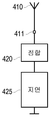
도 4는 현재 개시된 실시형태에 따른 위치 반사기의 기능적 블록 선도;
도 5는 현재 개시된 실시형태에 따른 다른 위치 반사기의 기능적 블록 선도;
도 6은 현재 개시된 실시형태에 따른 다른 위치 반사기의 기능적 블록 선도;
도 7은 현재 개시된 실시형태에 따른 다른 위치 반사기의 기능적 블록 선도;
도 8은 현재 개시된 실시형태에 따른 다른 위치 반사기의 기능적 블록 선도;
도 9는 현재 개시된 실시형태에 따른 위치 반사기의 등측도;
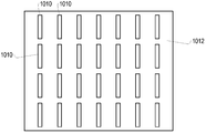
도 10은 현재 개시된 실시형태에 따른 위치 반사기의 평면도;
도 11은 현재 개시된 실시형태에 따른 다른 위치 반사기의 평면도;
도 12는 현재 개시된 실시형태에 따른 송신 및 수신 레이더 체인의 기능적 블록 선도;
도 13은 현재 개시된 실시형태에 따른 대안의 안테나 배열을 갖는 추가적 송신 및 수신 레이더 체인의 기능적 블록 선도;
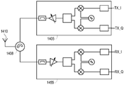
도 14는 현재 개시된 실시형태에 따른 다른 대안의 안테나 배열을 갖는 추가적 송신 및 수신 레이더 체인의 기능적 블록 선도;
도 15는 현재 개시된 실시형태에 따른 측위 신호 프로세싱의 기능적 블록 선도;
도 16은 현재 개시된 실시형태에 따른 송신 측위 신호 프로세싱의 기능적 블록 선도;
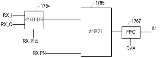
도 17은 현재 개시된 실시형태에 따른 수신 측위 신호 프로세싱의 기능적 블록 선도; 및
도 18은 현재 개시된 실시형태에 따라 위치 측위를 결정하기 위한 프로세스의 순서도.The details of the present invention can be obtained in part by examining the accompanying drawings, both for their structure and for their operation, in which like reference numerals refer to like parts:
1 is a functional block diagram of an indoor positioning system according to the presently disclosed embodiment;
2 is an illustration of an example positioning according to the presently disclosed embodiment;
3 is an illustration of another example of positioning according to the presently disclosed embodiment;
4 is a functional block diagram of a position reflector according to the presently disclosed embodiment;
5 is a functional block diagram of another position reflector according to the presently disclosed embodiment;
6 is a functional block diagram of another position reflector according to the presently disclosed embodiment;
7 is a functional block diagram of another position reflector according to the presently disclosed embodiment;
8 is a functional block diagram of another position reflector according to the presently disclosed embodiment;
9 is an isometric view of a position reflector according to the presently disclosed embodiment;
10 is a plan view of a position reflector according to the presently disclosed embodiment;
11 is a plan view of another position reflector according to the presently disclosed embodiment;
12 is a functional block diagram of a transmit and receive radar chain according to the presently disclosed embodiment;
13 is a functional block diagram of an additional transmitting and receiving radar chain with an alternative antenna arrangement according to the presently disclosed embodiment;
Figure 14 is a functional block diagram of an additional transmitting and receiving radar chain with another alternative antenna arrangement according to the presently disclosed embodiment;
15 is a functional block diagram of positioning signal processing in accordance with the presently disclosed embodiment;
16 is a functional block diagram of the transmitted positioning signal processing according to the presently disclosed embodiment;
17 is a functional block diagram of received positioning signal processing according to the presently disclosed embodiment; And
18 is a flowchart of a process for determining position location in accordance with the presently disclosed embodiment.
휴대용 무선 모바일 디바이스가 레이더 반사기를 사용하여, 예컨대, 센티미터 레벨까지 정확하게 그들 실내 위치를 결정할 수 있게 하는 시스템 및 방법이 개시된다. 내장 고정된 RF 지연을 갖는 주파수, 및/또는 코딩된 신호, 스캐닝된 재귀-지향성 또는 재귀-반사성 수동 레이더 반사기가 사용될 수 있다. 그러한 반사기는 소정 실내 공간의 천장, 벽 또는 바닥 상에 어딘가에 놓일 수 있고 그리고 그들 위치 및 정향은 모바일 디바이스에 이용가능하게 될 수 있다. A system and method for enabling a portable wireless mobile device to determine their indoor position accurately, e.g., to a centimeter level, using a radar reflector is disclosed. Frequency with built-in fixed RF delay, and / or coded signal, scanned recursive-directional or recursive-reflective passive radar reflector may be used. Such a reflector may be placed somewhere on the ceiling, wall or floor of a given interior space and their position and orientation may be made available to the mobile device.
모바일 디바이스는 특수 코딩된 레이더 파형을 사용하여 그것과 소정 인근 반사기 간 거리는 물론 반사기에서의 방위 및 고도 도래각(angle of arrival: AOA) 또한 측정함으로써 그 위치를 정확하게 결정할 수 있다. 기지의 위치 및 정향의 소정 반사기에 상대적으로 그 거리 및 각도를 결정할 수 있는 것에 의해, 모바일 디바이스는 하나의 수동 반사기만을 사용하여 3-차원 공간에서의 그 위치를 결정할 수 있다. 다수의 반사기로부터의 반사를 검출하는 것은 컴퓨팅된 정확도를 증가시킬 수 있다. 더욱, 반송파 위상 레인지 결정 기술은 다양한 실내 환경 하에서 개선된 정확도를 내놓도록 채용될 수 있다. 마지막으로, 반사기의 수동 본성 및 낮은 프로파일 설계를 고려하면, 예컨대, 배선 또는 측량 없이 그것들을 천장 타일 위에 놓거나 또는 그것들을 실내 공간 내 어느 평탄한 그리고 가로막히지 않은 표면에라도 부착함으로써 상업용 환경에서도 그리고 주거용 환경에서도 그들 설치는 간단하다. 설치되고 나면, 배터리 교체 또는 재교정과 같은 유지보수는 필요하지 않다. 더욱, 그러한 반사기는 느슨한 공차를 갖는 매우 적은 수동 컴포넌트를 포함하고 있고, 그래서 생산 비용이 매우 저렴하다. 이들 반사기는 또한 전형적으로 평탄하고 눈에 띄지 않고 그리고 예컨대 건물의 건식벽 상에, 뒤에 또는 내장되어 영구적으로 설치될 수 있다. The mobile device can precisely determine its position using a specially coded radar waveform and by measuring the azimuth and elevation angle of arrival (AOA) at the reflector, as well as the distance between it and the nearest reflector. By being able to determine its distance and angle relative to a given reflector of known position and orientation, the mobile device can determine its position in three-dimensional space using only one passive reflector. Detecting reflections from multiple reflectors can increase the computed accuracy. Furthermore, carrier phase range determination techniques can be employed to provide improved accuracy under a variety of indoor environments. Finally, considering the passive nature of the reflectors and the low profile design, for example, they can be placed on ceiling tiles without wiring or surveying, or they can be attached to any flat and uncluttered surface in the interior space, Their installation is simple. Once installed, maintenance such as battery replacement or recalibration is not required. Moreover, such a reflector includes very few passive components with loose tolerances, so the production cost is very low. These reflectors are also typically flat and inconspicuous and can be permanently installed, for example, on or behind the drywall of a building.
현재 개시된 방법 및 시스템과 사용된 반사기는 다양한 형태 및 기능을 갖는다. 일부 반사기는 레인징 정보를 제공한다. 다른 반사기는 방위, 고도 또는 양자와 같은 각도 정보를 제공한다. 반사기는 또한 레인징 정보도 그리고 각도 정보도 제공할 수 있다. 반사기는 레이더 반사기, 위치 반사기, 측위 반사기, 또는 유사한 용어로 지칭될 수 있다. 부가적으로, 반사기는 특정 반사기의 특성을 설명하는 형용사를 사용하여 지칭될 수 있으며, 예컨대, 복합 반사기, 지연된 반사기, 주파수 스캐닝된 반사기, 주파수 스캐닝된 재귀-지향성 반사기, 스캐닝되지 않은 재귀-반사성 레이더 반사기, 수평 스윕 반사기, 수직 스윕 반사기, 선형 반사기, 수동 반사기, 또는 섹터링된 반사기이다. The presently disclosed methods and systems and reflectors used have various forms and functions. Some reflectors provide ranging information. Other reflectors provide angle information such as azimuth, elevation, or both. The reflector can also provide ranging information and angle information. The reflector may be referred to as a radar reflector, a position reflector, a position reflector, or similar terminology. Additionally, the reflector may be referred to using an adjective that describes the characteristics of a particular reflector, such as a complex reflector, a delayed reflector, a frequency scanned reflector, a frequency scanned recursive-directional reflector, an unscanned recursive- A reflector, a horizontal sweep reflector, a vertical sweep reflector, a linear reflector, a passive reflector, or a sectored reflector.
일 실시형태에서, 모바일 디바이스는 벽 또는 천장 장착된 RF 반사기에 의해 반사될 레이더 신호를 송신하는 회로를 포함한다. 반사기는 내부 지연을 포함할 수 있다. 반사기는 주파수-스캐닝된 페이징된 어레이 유형 안테나 구조일 수 있다. 주파수 스캐닝된 페이징된 어레이 안테나 구조는 여기 주파수에 기반하여 소정 방향으로 높은 이득 로브를 가지는 안테나 구조이다(예컨대, "Antennas", 제2판, John Kraus, 1988년, 11-11절 참조). 여기 주파수가 변화됨에 따라, 안테나의 이러한 주된 높은 이득 로브의 방향각 또한 변한다. 유사한 안테나 구조가 레이더 설치에서 사용되어 왔는데 여기 주파수를 스윕하는 것에 의해 구조는 구조로부터 집중된 방사각의 방향을 스윕하도록 되어 있다. 안테나 구조의 가역 본성을 고려하면, 소정 주파수에 대해 방사가 최대화되는 방향은 또한 동일한 주파수에서 최대 수신 감도의 방향이다. 이들 유형의 안테나 구조는 그것들이 전형적으로는 페이징된 어레이 안테나 매트릭스로 이루어지더라도 하나의 접속 포트만을 갖는다. 소자의 페이징은 안테나 구조의 단일 포트로부터 구조 내 방사 소자로의 RF 전력 분배/결합 분기 트레이스에 페이징 지연을 삽입함으로써 달성된다. 위치 반사기는 방의 천장 구석에 설치될 수 있다. 그러한 경우에, 필요한 스윕 각도는 90도 미만일 수 있다. 일 실시형태에서, 이들 반사기는, 상당한 역방향 감도 없이, 방의 방향으로만 비-영 이득을 갖는 그러한 방식으로 이루어진다. 이것은 인접 방 또는 층으로부터의 신호와 상호작용하거나 반사할 가능성을 감축할 수 있다. In one embodiment, the mobile device includes circuitry for transmitting radar signals to be reflected by a wall or ceiling mounted RF reflector. The reflector may include an internal delay. The reflector may be a frequency-scanned paged array type antenna structure. The frequency scanned paged array antenna structure is an antenna structure having a high gain lobe in a predetermined direction based on the excitation frequency (e.g., "Antennas ", 2nd ed., John Kraus, 1988, 11-11). As the excitation frequency changes, the direction angle of this main high gain lobe of the antenna also changes. Similar antenna structures have been used in radar installations, and by sweeping the excitation frequency, the structure is adapted to sweep the direction of the centralized radiation angle from the structure. Considering the reversible nature of the antenna structure, the direction in which radiation is maximized for a given frequency is also the direction of maximum receiving sensitivity at the same frequency. These types of antenna structures have only one connection port, even though they typically consist of a phased array antenna matrix. Paging of the device is accomplished by inserting a paging delay into the RF power distribution / coupling branch trace from a single port of the antenna structure to the in-structure radiating element. The position reflector can be installed in the ceiling corner of the room. In such cases, the required sweep angle may be less than 90 degrees. In one embodiment, these reflectors are made in such a way that they have a non-zero gain only in the direction of the room, without significant backward sensitivity. This can reduce the likelihood of interacting with or reflecting signals from adjacent rooms or layers.
다른 실시형태에서, 반사기는 방위 및 고도 AOA 양자를 내놓도록 설계된다. 단일 선형 페이징된 어레이는 하나의 각도를 따른 호를 스윕할 수 있다. 반사기가 2개의 각도를 내놓는 것을 가능하게 하기 위해, 복합 반사기는 하나가 수직으로 다른 하나가 수평으로 스윕하는 2개의 병설된 반사기를 포함할 수 있다. 병설된 반사기의 각각은 다른 부-대역의 여기에 응답한다. 모바일은 각각의 부-대역에 대한 주파수 스윕을 송신하고 그리고 방위 및 고도 AOA를 별개로 검출한다. 일부 안테나는 여기 주파수의 함수로서 래스터 스캔을 산출할 수 있고 그리하여 하나의 주파수 스윕으로 방위각 및 고도각을 내놓을 수 있다.In another embodiment, the reflector is designed to provide both azimuth and elevation AOAs. A single linear phased array can sweep arcs along one angle. To enable the reflector to emit two angles, the composite reflector may include two side-by-side reflectors, one of which vertically sweeps the other one horizontally. Each of the assembled reflectors responds to excitation of the other sub-band. The mobile transmits a frequency sweep for each sub-band and detects the azimuth and altitude AOA separately. Some antennas can produce a raster scan as a function of the excitation frequency and thus provide azimuth and elevation angles with a single frequency sweep.
일 실시형태에서, 모바일 디바이스는 연속적 스윕 중심 주파수를 갖는 레이더 신호를 송신한다. 어떤 순간에, 이러한 레이더 신호의 주파수는 모바일 디바이스의 방향으로 최대 안테나 이득을 초래하는 주파수와 같다. 이러한 시점에서, 모바일은 반사기로부터 되돌아 모바일로의 최대 반사 신호 전력을 검출한다. 이러한 주파수를 주목하고 그리고 모바일이 이러한 안테나 반사기에 대해 주파수의 함수로서 방사의 각도, 정향 및 위치에 대해 네트워크로부터 이미 가지고 있는 정보를 사용함으로써, 모바일은 거처하는 모바일이 따르는 안테나 구조에 상대적인 각도를 컴퓨팅할 수 있다. 부가적으로, 신호의 송신과 반사의 후속 검출 간 왕복 지연을 측정함으로써, 모바일은 또한 모바일 위치와 반사기 간 거리를 컴퓨팅할 수 있다. 반사기의 위치 및 정향에 대한 지식을 가지고 이러한 반사기까지의 거리 및 AOA를 검출하여, 모바일은 3D 공간에서의 그 위치를 계산할 수 있다. 매우 높은 정확도를 달성하기 위해, 반송파 위상 레인징 기술이 사용될 수 있다.In one embodiment, the mobile device transmits a radar signal having a continuous sweep center frequency. At any moment, the frequency of this radar signal is equal to the frequency that results in the maximum antenna gain in the direction of the mobile device. At this point, the mobile detects the maximum reflected signal power from the reflector back to the mobile. By noting this frequency and using the information that the mobile already has from the network about the angle, orientation and location of radiation as a function of frequency for this antenna reflector, the mobile is able to calculate the angle relative to the antenna structure can do. Additionally, by measuring the round trip delay between the transmission of the signal and the subsequent detection of the reflection, the mobile can also compute the distance between the mobile position and the reflector. Having knowledge of the position and orientation of the reflector and detecting the distance to this reflector and AOA, the mobile can calculate its position in 3D space. In order to achieve very high accuracy, a carrier phase ranging technique may be used.
일 실시형태에서, 모바일은 특정 폭의 주파수를 스윕하는 레이더 신호를 송신하여 가장 높은 반사 전력을 찾는다. 가장 높은 반사 전력을 갖는 주파수는 모바일의 방향으로 최대 반사를 초래하는 주파수이다. 이러한 지점에서, 모바일은 모바일이 많이 이동하지는 않았을 수 있으므로 후속 위치 고정에 대해 주파수 스윕을 이러한 중심 주파수에 가까운 주파수로 한정할 수 있다. 이것은 검색 시간을 감축하고 송신 전력을 감축한다. 모바일에서 전력 제어를 사용하여, 즉, 최소 검출가능한 반사 전력을 갖는 반사를 초래하는 신호를 송신하도록 소정 레이더 신호에 대한 방사 전력을 감축 또는 증가시킴으로써, 모바일은 배터리 수명을 증가시키고 다른 가까운 옆 디바이스에 대한 간섭을 감축할 수 있다. 부가적으로, 반사기와 관련하여 소정 각도만큼 떨어져 있는 2개의 모바일은 안테나에 대한 그들 AOA가 다르므로 그들 레이더 신호에 대해 다른 주파수를 사용하고 있을 것이다. 이것은 하나의 반사기가 소정 구역 내 다수의 모바일 디바이스를 동시에 취급할 수 있으므로 시스템의 용량을 증가시키고 그리고 여기기의 방향으로 향한 반사기 안테나 재귀-지향성 방사 집중에 기반하는 안테나 이득 섹터화 및 상이한 주파수 때문에 최소 상호 간섭을 갖는다. 매우 가까이 공동 위치하고 있는 모바일들의 경우에는, 각각의 디바이스가 그 자신의 신호를 다른 것들의 신호와 구별할 수 있도록 시분할, 주파수 분할 또는 코드 분할 다중 액세스 기술이 사용될 수 있다. In one embodiment, the mobile searches for the highest reflected power by transmitting a radar signal that sweeps frequencies of a certain width. The frequency with the highest reflected power is the frequency that causes the maximum reflection in the direction of the mobile. At this point, the mobile may limit the frequency sweep to a frequency near this center frequency for subsequent position fixes, since the mobile may not have moved much. This reduces search time and reduces transmission power. By reducing or increasing the radiated power for a given radar signal to transmit a signal that uses the power control at the mobile, i. E., To cause a reflection with a minimum detectable reflected power, the mobile increases the battery life, The interference can be reduced. Additionally, two mobiles spaced a certain distance in relation to the reflector will be using different frequencies for their radar signals because their AOAs for the antennas are different. This is because one reflector can simultaneously handle multiple mobile devices in a given area, increasing the capacity of the system and reducing the antenna gain sectorization and the different frequencies based on the reflector antenna recursive- Interference. In the case of mobiles that are very closely co-located, time division, frequency division or code division multiple access techniques may be used so that each device can distinguish its own signal from others.
일 실시형태에서, 반사기 안테나에서 수신된 신호는 모바일로 되돌아 재방사되기 전에 지연된다. 지연은 전형적으로는 일 마이크로초의 몇 분의 일 내지 수 마이크로초의 차수이지만 더 크거나 더 작을 수 있다. 이것은, 벌크 음향파(BAW) 디바이스, 부하 있는 지연 라인, LC 지연 라인, 표면 음향파(SAW) 디바이스 또는 다른 RF-음향 방법(예컨대, PAL TV 표준을 지원하도록 휴대용 비디오 카메라에 의해 이전에 사용된 것들과 유사함)과 같은 여러 수동 RF 컴포넌트에 의해 달성될 수 있다. 부가적으로, 신호는 그룹 지연이 임의로 길게 될 수 있는 음의 유전율 및/또는 투자율을 갖는 새롭게 개발된 메타-재료 구조를 사용함으로써 지연될 수 있다.In one embodiment, the signal received at the reflector antenna is delayed before it is redirected back to the mobile. The delay is typically in the order of a few microseconds to a few microseconds, but may be larger or smaller. This may be achieved by using a bulk acoustic wave (BAW) device, a loaded delay line, an LC delay line, a surface acoustic wave (SAW) device or other RF- Which can be achieved by various passive RF components, such as the < Desc / Clms Page number 7 > Additionally, the signal can be delayed by using a newly developed meta-material structure with a negative permittivity and / or permeability that group delays can be arbitrarily long.
BAW 필터를 사용하는 실시형태의 경우에, 안테나 급전선의 입력은 BAW 필터의 일측에 정합 및 접속되는 한편, 필터의 타측은 접지에 단락된다. BAW 필터는 레이더 송신 신호에서의 에너지 전부를 통과시키도록 선택될 수 있다. 안테나에서 수신된 신호는 불가피한 부정합에 기인하여 불가피한 즉각적 반사를 갖는다. 그때 신호의 벌크는 BAW 필터에 공급된다. BAW 필터를 통한 하나의 전파 지연 시간 후에 신호는 접지로의 단락에 의해 완전 반사된다. 신호는 안테나 구조를 구동하고 모바일 디바이스의 방향으로 되돌아 재방사하기 전에 다른 하나의 전파 지연 시간을 경험한다. 이러한 실시형태에서, 모바일은 소정 반사기의 이러한 지연을 선험적으로 알고 있고 그리고 모바일과 이러한 반사기 간 참 물리적 거리를 계산하기 위해 그것을 왕복 지연 계산으로부터 감산한다.In the case of an embodiment using a BAW filter, the input of the antenna feed line is matched and connected to one side of the BAW filter while the other side of the filter is shorted to ground. The BAW filter may be selected to pass all energy in the radar transmit signal. The signal received at the antenna has unavoidable immediate reflection due to unavoidable mismatch. The bulk of the signal is then fed to the BAW filter. After one propagation delay time through the BAW filter, the signal is fully reflected by a short to ground. The signal experiences another propagation delay time before driving the antenna structure and redirecting back to the direction of the mobile device. In this embodiment, the mobile a priori knows this delay of a given reflector and subtracts it from the round trip delay calculation to calculate the true physical distance between the mobile and this reflector.
레이더 펄스를 그것을 되돌려 송신 모바일로 반사하기 전에 지연시킴으로써 여러 이점이 달성된다. 우선, 모바일로부터의 송신 레이더 신호는 전형적 방에 대해 약 90ns 지연 스프레드 내지 쇼핑 센터에 대해 200ns 지연 스프레드를 가질 수 있다. 이것은 신호가 환경 장애물로부터의 기생 반사에 기인하는 검출가능한 전력을 계속 고집하는 시간이다(예컨대, "OFDM For Wireless Multimedia Communications", R. Van Nee 및 R. Prasad, 2000년, 1.3절 참조). 각각의 반사기에서의 수신 신호를 이러한 시간보다 더 긴 시간만큼 지연시킴으로써, 거울 또는 전기적으로 큰 금속 물체로부터와 같은, 기생 환경 반사에 기인하는 거짓 위치 결정은 제거되는데 최소 반사기 지연보다 더 긴 지연 후에 수신된 신호는 반사기로부터만 유래할 수 있기 때문이다. 그래도, 전도 물체에서 그 진로를 따라 모바일로 또한 반사하는 반사기로부터의 반사 신호를 여전히 얻는 것이 가능하다. 이러한 다중경로 기생 신호는 반사기에서의 지연에 기인하는 직접적 기생 반사보다 훨씬 더 낮은 발생 확률을 가지고 그리고 그 효과는 반사기가 시선 반사의 확률을 최대화하는 장소에 놓임을 확실히 함으로써 더 감축될 수 있다. 또한, 대부분의 경우에, 큰 기생 반사기는 벽 상에 또는 그 가까이에 위치하고 있다. 모바일이 또한 반사기에서의 입사각을 알고 있기 때문에, 그리고 그러한 반사기가 방 표면에 가까이 있기 때문에, 잘못된 컴퓨팅된 위치는 전형적으로 방 범위에 기인하는 비논리적 물리적 위치를 초래하고 그에 따라 다뤄질 수 있다. Several advantages are achieved by delaying the radar pulse before it is reflected back to the transmitting mobile. First, the transmitted radar signal from the mobile may have a delay spread of about 90ns for a typical room or a 200ns delay spread for a shopping center. This is the time at which the signal remains persistent for detectable power due to parasitic reflections from environmental obstructions (see, for example, " OFDM For Wireless Multimedia Communications ", R. Van Nee and R. Prasad, 2000, section 1.3). By delaying the received signal at each reflector by a time longer than this time, false position determination due to parasitic environment reflections, such as from a mirror or an electrically large metal object, is eliminated, and after a longer delay than the minimum reflector delay Since the resulting signal can only originate from the reflector. Still, it is still possible to obtain a reflected signal from the reflector that also reflects to the mobile along its course from the conducting object. This multi-path parasitic signal can be further reduced by having a much lower probability of occurrence than the direct parasitic reflection due to delay in the reflector and ensuring that the effect is placed where the reflector maximizes the probability of eye reflection. Also, in most cases, the large parasitic reflector is located on or near the wall. Because the mobile also knows the angle of incidence at the reflector, and because such a reflector is close to the surface of the room, the erroneously computed location typically results in a illogical physical location due to the range of the room and can be handled accordingly.
부가적으로, 반사기에 삽입된 내부 지연은 모바일이, 광속을 사용하여 물리적 공간에 매핑될 때, 모바일 디바이스와 반사기 간 전형적 최대 실내 거리보다 훨씬 더 긴 레이더 파를 송신할 수 있게 하는 한편, 동시에 여전히 송신 신호와 반사 신호가 모바일에서 중첩하지 않을 수 있게 한다. 더 긴 레이더 신호는 송신기에 대해 더 높은 거리 분해능 및 더 양호한 더 낮은 피크 대 평균 비를 초래한다. 비-중첩은 또한 모바일이 신호 송신 모드에 대해서든 반사 수신 모드에 대해서든 교번 비-중첩 시간을 할당할 수 있음을 의미한다. 교번 비중첩 시간으로 송신 및 수신 동작 모드를 스케줄링함으로써, 되돌아 RX 측으로의 TX 신호 누설은 TX와 RX가 동시에 일어나지 않음에 기인하여 회피되므로 수신기 전단 회로는 크게 단순화된다. Additionally, the internal delay introduced into the reflector allows the mobile to transmit radar waves that are much longer than the typical maximum indoor distance between the mobile device and the reflector when mapped to physical space using the speed of light, Allowing the transmitted and reflected signals to not overlap in the mobile. Longer radar signals result in higher distance resolution and better lower peak to average ratios for the transmitter. Non-overlap also means that the mobile can assign an alternate non-overlap time, either for the signal transmission mode or for the reflective reception mode. By scheduling the transmit and receive operation modes with alternate non-overlapping times, the TX signal leakage back to the RX side is avoided because TX and RX do not occur at the same time, and the receiver front-end circuit is greatly simplified.
부가적으로, 레이더 신호는 직접 시퀀스 확산 스펙트럼(direct sequence spread spectrum: DSSS) 위상 변조를 사용하여 인코딩될 수 있다. 이들 시스템에서, 내부 반사기 지연은 내장 반사기 지연이 하나보다 많은 칩 지연 분리를 보장하면 송신 신호와 그 반사 간 구별하는 것을 용이하게 한다.Additionally, the radar signal may be encoded using direct sequence spread spectrum (DSSS) phase modulation. In these systems, the inner reflector delay facilitates distinguishing between the transmit signal and its reflection if the inner reflector delay guarantees more than one chip delay separation.
소정 반사기 내 신호의 지연은 알려져 있을 수 있고 연속 기반으로 타이트 제어될 수 있다. 이것은 이러한 지연이 왕복 지연에 직접 부가되고 그리고, 온도 드리프트 또는 컴포넌트 노화에 기인하는, 그 이전에 발행된 지연과 실제 지연 간 어느 불일치라도 모바일 디바이스와 반사기 간 거리를 컴퓨팅하는데 직접적 오차를 초래하기 때문이다. 실제 지연을 연속적으로 측정하고 주기적 교정 프로세스에 의해 적시 방식으로 재발행하는 것이 가능하기는 하지만, 여기에서 개시된 교번 실시형태는 이것을 교번 방식으로 다룬다. The delay of the signal in a given reflector can be known and can be tightly controlled on a continuous basis. This is because this delay is directly added to the round trip delay and any discrepancy between the previously issued delay and the actual delay due to temperature drift or component aging will result in a direct error in computing the distance between the mobile device and the reflector . Although it is possible to continuously measure the actual delay and reissue in a timely manner by a periodic calibration process, the alternate embodiments disclosed herein deal with this in an alternating manner.
일 실시형태에서, 반사기는 수신된 레이더 신호를 지연시키도록 BAW 필터를 사용한다. 모든 전력을 반사하는 대신에, 반사기는 수신 신호에 대해 BAW 디바이스에 안테나 구조의 임피던스를 정합시키는 방향성 결합기를 내부적으로 사용한다. BAW의 타측 상에서 접지로의 단락에 의해 반사된 BAW 내 신호는 BAW의 입력 포트로 향하여 반사된다. 이러한 방향으로, 원래 신호의 일부가 안테나 구조로 되돌아 결합하고 모바일로 되돌아 방사되는 한편 나머지 부분이 BAW로 되돌아 반사되게 하는 의도적 부정합이 존재한다. 이러한 전향된 나머지 부분 중 일부는 BAW 내 다른 왕복 지연 후 안테나에 결합할 수 있게 되고 그리고 사이클은 반복된다. 예컨대, 일 실시형태에서, 부정합은 원래 신호의 4/5 또는 -1dB가 안테나에 결합할 수 있게 하고 1/5을 다시 사이클링할 것이다. 제2 반사 상에서, 안테나는 원래 신호의 4/5 x 1/5 = 4/25 또는 약 -8dB을 재방사할 것이다. 다음 반사는 4/5 * 1/5 * 1/5 = 4/125 등일 것이다. 여기에서 중요한 사실은 모바일이 2 곱하기 BAW 지연 더하기 자유 대기 왕복 지연 후에 신호의 일부를 수신할 것이라는 것이다. 그것은 나중에 정확히 4 곱하기 BAW 지연 더하기 동일한 자유 대기 왕복 지연에서 다른 신호를 수신할 것이다. 이들 2개의 눈금값을 고려하면, 모바일은 BAW 왕복 지연을 정확하게 측정하고, 그것을 제1 반사 왕복 지연의 측정치로부터 감산하고 그리하여 모바일로부터 반사기까지의 거리를 정확하게 결정할 수 있다. 이것은 온 더 플라이 행해지므로, 반사기의 설치 후에 교정, 정합 또는 측정이 반복될 필요가 없는데 모바일이 온도 및 컴포넌트 노화에 기인하는 가능한 작은 지연 드리프트에 대해 조절할 수 있기 때문이다. BAW 그룹 지연에 부과된 제조 공차는 상당히 완화될 수 있고 그리고 발행된 반사기 지연은 근사적일 필요가 있을 뿐이다. 설계 절충은 어떤 비율을 되돌아 안테나로 결합할지 그리고 어떤 부분을 되돌아 BAW로 반사할지 선택하는 것을 수반한다. 많은 부분이 안테나에 결합하게 하는 것은 제1 반사의 SNR을 증가시키지만 후속 반사는 검출하기에 너무 약할 수 있다. 대조적으로, 많은 부분을 되돌아 BAW에 결합시키는 것은 제1 반사를 약화시키고 그리고 구조는 오랜 시간 동안 잔류 에너지를 재-방사하기를 계속한다. 예컨대, ¼이 선택되면, 안테나로부터의 제1 반사는 원래 수신 전력으로부터 아래 -1.25dB일 것이다. 제2 반사는 원래 수신 전력으로부터 아래 약 -7dB일 것이고 그리고 제3 반사는 -13.25dB 등이다. 대안으로, 1/10이 사용되면, 반사 신호 전력은 각각 -1dB, -10.45dB, -19.9dB일 것이다. 모바일은 제2 반사를 한 번만 프로세싱할 필요가 있을 뿐이고, 그 후에 모바일은 BAW에서의 지연이 단시간 기간에 눈에 띄게 변할 것으로 예상되지 않으므로 제1 반사를 프로세싱할 필요가 있을 뿐임을 주목한다. 더욱, 강력한 신뢰도를 갖는 이러한 반사기 지연 결정을 수행한 모바일 디바이스는 이러한 측정 값을 신뢰도 표시자와 함께 다른 모바일에 의해 사용되도록 공중 서버에 업로드한다. 교정 신뢰도에 종속하여, 다른 모바일은 스스로 측정을 반복하기보다는 이러한 최근 발행된 값을 사용하기를 택할 수 있다. 우리는 명확함을 위해 지연 소자 삽입 손실을 무시하였음을 주목한다. 실제로, 반사 신호는 지연 소자 내에서의 각각의 왕복 전파에 대해 지연 소자의 2개의 삽입 손실을 발생시킬 것이다. 우리는 또한 BAW 필터가 일례로서 지연에 사용된다고 가정하였다. 다른 지연 소자도 사용될 수 있다. In one embodiment, the reflector uses a BAW filter to delay the received radar signal. Instead of reflecting all power, the reflector internally uses a directional coupler to match the impedance of the antenna structure to the BAW device for the received signal. The signal in the BAW reflected by the short to ground on the other side of the BAW is reflected towards the input port of the BAW. In this direction, there is intentional mismatch where a portion of the original signal couples back to the antenna structure and is radiated back to the mobile while the remainder is reflected back to the BAW. Some of these diverted remainder are allowed to couple to the antenna after another round trip delay in the BAW and the cycle is repeated. For example, in one embodiment, the mismatch will allow 4/5 or -1 dB of the original signal to couple to the antenna and again cycle 1/5. On the second reflection phase, the antenna will re-radiate 4/5 x 1/5 = 4/25 or about-8dB of the original signal. The next reflection will be 4/5 * 1/5 * 1/5 = 4/125, and so on. The important fact here is that the mobile will receive a fraction of the signal after a 2 times BAW delay plus a free-waiting round trip delay. It will receive another signal at exactly the same 4 times BAW delay plus the same free-waiting round trip delay later. Taking into account these two scales, the mobile can accurately measure the BAW round trip delay and subtract it from the first round trip delay measurement, thus accurately determining the distance from the mobile to the reflector. This is done on the fly, so calibration, registration or measurement need not be repeated after the installation of the reflector, since the mobile can adjust for possible small delay drift due to temperature and component aging. The manufacturing tolerances imposed on BAW group delays can be considerably mitigated and the emitted reflector delays only need to be approximate. The design trade-off entails choosing what ratio to combine with the antenna back and which part to return back to the BAW. Having a large portion coupled to the antenna increases the SNR of the first reflection but the subsequent reflection may be too weak to detect. In contrast, combining large amounts back to BAW weakens the first reflections and the structure continues to re-radiate residual energy for a long time. For example, if ¼ is selected, the first reflection from the antenna will be -1.25 dB below the original received power. The second reflection would be about -7dB below the original received power and the third reflection would be -13.25dB and so on. Alternatively, when 1/10 is used, the reflected signal power will be -1 dB, -10.45 dB, -19.9 dB, respectively. Note that the mobile only needs to process the second reflection once and then the mobile only needs to process the first reflection since the delay in the BAW is not expected to change noticeably in the short time period. Moreover, the mobile device that has performed this reflector delay determination with strong reliability uploads these measurements to the public server for use by other mobile with confidence indicators. Depending on the calibration reliability, the other mobile may choose to use these recently issued values rather than repeat the measurements themselves. Note that we ignore the delay element insertion loss for the sake of clarity. In practice, the reflected signal will cause two insertion losses of the delay element for each round trip wave in the delay element. We also assumed that the BAW filter is used for delay as an example. Other delay elements may be used.
지금까지 우리는 모바일이 소정 반사기로부터의 그 거리를 그 반사기에서의 AOA에 부가하여 어떻게 결정할 수 있는지 설명하였다. 모바일이 그 위치를 올바르게 결정하기 위해, 그것은, 부근에 하나보다 많은 반사기가 있는 경우에, 소정 신호 반사가 어느 반사기로부터 유래하고 있는지 결정하여야 한다. 그것은 또한 그 반사기의 위치 및 정향을 각각의 반사기에 대한 주파수 대 AOA 도래 특성 및 반사기의 제1 반사에 대한 부분 반사 전력 비와 함께 알고 있어야 한다. 주파수 대 AOA 도래 특성, 근사적 매립된 지연, 및 제1 반사에 대한 부분 반사 전력 비율은 그러한 반사기의 제조 프로세스 동안 측정에 의해서든 설계에 의해서든 결정될 수 있고 그리고 고유 반사기 유형 번호는 소정 반사기 변종과 연관된 각각의 구별되는 특성과 연관될 수 있다. 설치 동안, 각각의 설치되는 반사기의 물리적 위치 및 정향에 대한 엔트리, 주파수 특성 번호, 및 반사기 ID 번호를 포함하고 있는 룩업 테이블이 파퓰레이팅된다. 부가적으로, 있는 경우, 각각의 반사기가 채용하는 근사적 내장 지연을 제공하는 엔트리도 테이블에 포함된다. 이러한 정보는, 국부적이든 전역적이든, 인터넷 클라우드에서의 소정 서버 상에 상주하게 되고, 그리고 소정 부근 내 위치 측위 고정을 수행하도록 허용되는 모든 디바이스가 액세스가능하게 된다. 반사기의 위치 및 정향은 표준 지리적 측량 및 위치결정 데이터에 상대적으로 주어지거나 실내 랜드마크에 상대적으로 주어질 수 있다. 반사기 지연의 정확한 테이블 작성은 모바일이 위에서 설명된 부분 반사 방법으로부터 그것을 결정할 수 있으므로 엄격하게 필요한 것은 아니지만, 그럼에도 불구하고, 그것은 모바일이 가능한 반사를 경청하고 있는 시간을 감축하도록 제공될 수 있다. So far we have explained how the mobile can determine its distance from a given reflector by adding it to the AOA at its reflector. In order for the mobile to correctly determine its position, it must determine from which reflector a given signal reflection originates, in the presence of more than one reflector in the vicinity. It should also know the position and orientation of its reflector, along with the frequency vs. AOA arrival characteristics for each reflector and the partial reflection power ratio for the first reflection of the reflector. The frequency to AOA incoming characteristics, the approximate embedded delay, and the partial reflect power ratio for the first reflection can be determined by measurement or by design during the fabrication process of such a reflector, and the intrinsic reflector type number can be determined by a predetermined reflector variant Can be associated with each distinct characteristic associated with each other. During installation, a lookup table is populated that includes an entry for the physical location and orientation of each installed reflector, a frequency property number, and a reflector ID number. Additionally, if present, an entry that provides an approximate built-in delay employed by each reflector is also included in the table. This information resides on a given server in the Internet cloud, either locally or globally, and any device that is allowed to perform location locality fixation within a given neighborhood becomes accessible. The location and orientation of the reflector may be given relative to the standard geographical measurement and positioning data or relative to the indoor landmark. Though it is not strictly necessary, since the exact table creation of the reflector delay can be determined by the mobile from the partial reflection method described above, it can nevertheless be provided to reduce the time that mobile is listening to possible reflections.
모바일은 또한 소정 반사가 어느 반사기로부터 유래하고 있을 수 있는지 결정할 수 있다. 다양한 기술이 반사기 식별에 사용될 수 있다. 일 실시형태는 반사기 내, 벌크 음향파 디바이스(BAW)와 같은, 소정 지연 소자가 나타내 보이는 특성(예컨대, 지연 및/또는 필터링)에 기반한다. 이들 내장 반사기 지연은 가장 긴 자유 대기 왕복 지연보다 훨씬 더 크고 그리하여 가까운 근접 내 각각의 반사기가 그 이웃의 것들과는 다른 내장 지연을 나타내 보이게 함으로써 용이하게 구별가능할 수 있다. 또한, 이들 지연 소자들은 상이한 주파수 필터링 특성들을 가지고 그로써 올바른 반사기-반사 배정에 도움을 줄 수 있다.The mobile can also determine which reflection may be originating from which reflector. A variety of techniques can be used to identify the reflector. One embodiment is based on characteristics (e.g., delay and / or filtering) in which a given delay element is exhibited, such as a bulk acoustic wave device (BAW), in a reflector. These built-in reflector delays can be much larger than the longest free-waiting round trip delay so that each reflector in the near vicinity is easily distinguishable by showing a different built-in delay than those of its neighbors. In addition, these delay elements can have different frequency filtering characteristics and thereby aid in correct reflector-reflection assignments.
다른 실시형태는 반사 대 반사기의 잘못된 매핑을 배제하도록 모바일의 기지의 이전 또는 근사적 위치를 사용한다. 예컨대, 띄엄띄엄 위치하고 있는 수 개의 반사기가 있는 공간에서, 어떤 경우에는 모바일이 단 하나의 반사기로부터 반사를 수신하는 것이 가능하다. 그러한 반사를 사용하여, 모바일은 반사기에서의 AOA 및 그로부터의 거리를 결정할 수 있다. 이러한 정보를 사용하여, 모바일은, 인접 방 내에 그리고 위 및 아래 층에 거처하는 반사기를 포함하는, 확장된 부근에서의 각각의 반사기에 대해 이러한 거리 및 AOA에 기반하여 가능한 모바일 위치를 계산한다. 이전 및 최근 위치 고정으로부터 그 위치에 대한 근사적 아이디어를 가지거나 또는 실내 위치결정에 현재 채용된 다른 부정확한 방법 중 어느 것을 사용함으로써, 모바일은 잘못된 위치 전부를 신속히 높은 확률로 배제할 수 있고 그리하여 옳은 위치를 가려내고 그것이 검출되는데 그 순간 사용한 올바른 반사기를 결정할 수 있다. 이러한 실시형태의 개량은 그저 몇몇 예를 들자면 창문 바깥에 또는 바닥 아래에 또는 벽 내부에 있는 것과 같은 물리적으로 불가능한 위치에 기반하는 잘못된 위치를 버리는 것을 수반한다. 계산된 거리에 부가하여, 여기에서 설명된 시스템의 실시형태가 또한 반사기에서의 AOA를 결정한다는 사실은 거짓 위치를 검출하고 그리고 올바르게 식별된 반사기와 연관된 올바른 위치를 식별할 공산을 크게 개선함을 주목한다. 이러한 정보는 도움을 주는 정보로서 후속 고정에 사용될 수 있다. 칼만 필터링 기술은 더욱 결정된 위치가 잡음 있는 측정에 더 강건하게 하는데 사용될 수 있다.Other embodiments use the mobile's known or approximate location to preclude erroneous mapping of the reflector-reflector. For example, in a space with several reflectors positioned sparsely, in some cases it is possible for the mobile to receive reflections from only one reflector. Using such reflections, the mobile can determine the AOA at the reflector and the distance therefrom. Using this information, the mobile calculates possible mobile positions based on this distance and AOA for each reflector in the expanded vicinity, including reflectors that lie in the adjacent room and in the upper and lower layers. By having either an approximate idea of the location from previous and recent location fixes or using any of the other incorrect methods currently employed in indoor location, the mobile can quickly eliminate all of the wrong locations with a high probability, The position can be detected and it can be detected and the correct reflector used at that moment can be determined. Improvements to this embodiment involve discarding an erroneous location based on physically impossible locations, such as, for example, outside or at the bottom of a window or inside a wall. In addition to the calculated distances, the fact that the embodiment of the system described herein also determines the AOA in the reflector notices that it detects a false position and significantly improves the constellation to identify the correct position associated with the correctly identified reflector do. This information can be used for subsequent fixation as helpful information. Kalman filtering techniques can be used to make more determined positions more robust to noise measurements.
반사가 어느 반사기로부터 유래하는지 결정하기 위한 다른 실시형태는 레이더 신호 반사 전력을 사용하는 것을 수반한다. 반사기의 재귀-지향성 본성, 매립된 지연 정량화를 위한 위에서 개괄된 부분 전력 반사의 방법, 및 시선 조건이 정확한 위치를 위해 보급되어 있다고 예상된다는 사실을 고려하면, 반사가 소정 반사기로부터 유래하였다면 각각의 그 소정 반사기로부터 되돌아 왔을 예상된 전력 레벨을 소정 정확도로 계산하는 것이 가능하게 된다. 이것은 반사가 시선인지 아니면 벽, 천장 또는 바닥을 통해 오고 있는지의 부가적 표시를 준다. 그것은 또한 반사가 반사기와 모바일 디바이스 사이에서 다른 물체에서 튕기는지도 표시할 수 있다. 이러한 정보 전부는 검출된 반사를 각각의 반사기에 올바르게 배정하여 모바일 위치를 올바르게 결정하는데 도움을 준다. 그것은 또한 마지막 위치가 계산된 신뢰도를 결정한다. 더욱, 우리는 내장 반사기 지연의 정확한 측정이 가능하도록 사용된 각각의 반사기의 부분 반사 계수에 의해 각각의 반사기가 다른 것들과 다르게 함으로써 동일한 부근에서의 반사기들을 구별하려고 시도할 수 있다. 후속 반사들 간 전력 차이를 측정함으로써, 우리는 각각의 반사 신호에 대해 이러한 계수의 추정치를 결정할 수 있고 그리고 그 후 우리는 공중 테이블에서의 정보를 사용하여 특정 반사기와 그것을 연관시킬 수 있다. Another embodiment for determining which reflector is originating from which reflector involves using radar signal reflected power. Considering the recursive-directivity nature of the reflector, the method of partial power reflection outlined above for embedded delayed quantification, and the fact that the line of sight conditions are expected to be pervasive for accurate positioning, It becomes possible to calculate the expected power level that has come back from the predetermined reflector to a predetermined accuracy. This gives an additional indication of whether the reflection is through the line of sight, or through a wall, ceiling or floor. It can also indicate that reflection is bouncing off of other objects between the reflector and the mobile device. All of this information helps to correctly determine the mobile position by correctly assigning the detected reflection to each reflector. It also determines the confidence that the last position computed. Moreover, we can try to differentiate reflectors in the same vicinity by making each reflector different from the others by the partial reflection coefficient of each reflector used to allow an accurate measurement of the intrinsic reflector delay. By measuring the power difference between subsequent reflections, we can determine an estimate of this coefficient for each reflected signal, and then we can use that information in the public table to relate it to a particular reflector.
대체 실시형태에서, 우리는 부근에서의 반사기들이 상이한 주파수 대 주된 로브 스윕 각도 특성을 갖도록 설계할 수 있다. 예컨대, 일 실시형태에서, 하나의 반사기는 일 MHz의 주파수 스윕당 


공중 발행된 반사기 테이블에서의 어느 반사기로부터 소정 반사가 유래하고 있는지 결정하려고 추구하는 위 실시형태 중 전부는 모바일이 하나의 그리고 단 하나의 반사기로부터 반사를 수신한다고 가정하였다. 그렇지만, 모바일이 2개 이상의 반사기로부터 반사를 수신할 수 있으면, 어느 반사가 어느 반사기로부터 유래했는지 결정하는 것은 더 간단해진다. 대부분의 경우에 우리가 반사 대 반사기의 할당을 잘못 바꾸면, 새로운 컴퓨팅된 위치는 수렴에 대한 반사기에서의 AOA에 대해 측정된 것과는 매우 다른 최대 반사 주파수가 불가피하여 오차를 검출할 것이다. 그때 우리는 올바른 반사기-반사 배정으로 올바른 위치를 선택한다. 일부 경우에, 구체적으로는 모바일이 반사기들로부터 등거리에 그리고 동시에 그것들로부터 떨어져 있는 경우에, 올바른 반사-반사기 배정에서 추측하는 것은 더 난제가 된다. 다행히도, 그러한 배정 하에서, 올바른 및 틀린 반사기-반사 배정을 갖는, 컴퓨팅된 위치 양자는 서로 가깝고 그리고 가능한 잘못된 배정에 기인하는 위치 오차는 작다. 그럼에도 불구하고, 그러한 상황 하에서, 그리고 2개의 반사기로부터 멀리, 다른 반사기가 인근에 있을 것이고 더 정확한 위치를 주고 오차를 분해할 것이라고 예상된다. 우리는 반사기 위치결정에 유의함으로써 그러한 불량한 기하구조의 발생을 감축할 수 있다. 또한, 우리는 불량한 기하구조 발생을 더 감축하기 위해 수평 스윕 반사기를 수직 스윕 반사기와 혼합할 수 있다.All of the above embodiments, which seek to determine from which reflector in a publicly issued reflector table are derived a certain reflection, assumed that the mobile received reflections from one and only one reflector. However, if the mobile can receive reflections from more than one reflector, it becomes simpler to determine which reflections originate from which reflector. In most cases, if we incorrectly change the assignment of the reflector reflector, the new computed position will detect the error by the inevitable maximum reflection frequency, which is very different from that measured for AOA in the reflector for convergence. Then we choose the correct position with the correct reflector-reflection assignments. In some cases, it is more difficult to speculate in the correct reflector-reflector assignments, especially if the mobile is equidistant from and at the same time away from the reflectors. Fortunately, under such assignments, both the computed positions with the correct and wrong reflector-reflection assignments are close to each other and the position error due to possible misalignment is small. Nevertheless, under such circumstances, and away from the two reflectors, it is expected that another reflector will be nearby, giving a more precise position and resolving the error. We can reduce the occurrence of such poor geometry by taking care of reflector positioning. In addition, we can mix a horizontal sweep reflector with a vertical sweep reflector to further reduce the occurrence of poor geometry.
일 실시형태에서, 시스템은 반사를 그들 각각의 반사기에 올바르게 배정하고 그리하여 모바일의 위치의 올바른 계산을 초래하도록 위에서 개괄된 기술 및 방법 중 일부 또는 전부를 사용한다.In one embodiment, the system uses some or all of the techniques and methods outlined above to correctly assign reflections to their respective reflectors and thus to make a correct calculation of the position of the mobile.
여기에서 개시된 시스템은 이용가능한 면허 또는 무면허 대역을 포함하는 여러 RF 대역에서 동작할 수 있다. 주파수가 더 높을수록, 안테나 구조는 동일한 지향성 및 안테나 구조 이득 응답을 달성하기 위해 물리적으로 더 작을 필요가 있다. 또한, 더 높은 대역은 위치의 더 높은 공간적 분해능을 제공한다. 다른 한편, 더 높은 주파수는 모바일 디바이스에서 더 높은 전력 소비 및 더 고가의 Tx 및 Rx 전자부품을 초래한다. 반송파 위상 레인징 기술과 결합될 때 더 높은 주파수는 아래에서 논의되는 바와 같이 사용된 대역폭에 의해 그리고 이용가능한 신호-대-잡음 비에 의해서만 제한된 매우 정확한 위치 결정에 이른다. The system disclosed herein may operate in various RF bands including available licenses or unlicensed bands. The higher the frequency, the more the antenna structure needs to be physically smaller to achieve the same directivity and antenna structure gain response. In addition, the higher band provides a higher spatial resolution of the location. On the other hand, higher frequencies result in higher power consumption and higher cost Tx and Rx electronic components in mobile devices. When combined with carrier phase ranging techniques, the higher frequencies lead to highly accurate positioning, limited by the bandwidth used and only by the available signal-to-noise ratio, as discussed below.
소정 순간에 애플리케이션 요건에 의해 필요에 따라 동적으로 달라지는 정도의 정확도로 반사기까지의 모바일 거리의 양호한 추정치에 도달하기 위해 전술한 반사기와 함께 모바일에 의해 사용될 수 있는 레이더 신호의 구조가 이제 설명된다. 레인징 애플리케이션 내 정확도에 대한 이론적 한계는 크라머-라오 하한(Cramer-Rao lower bound; CRLB)에 의해 주어진다(예컨대, "Fundamentals of Radar Signal Processing", Mark A. Richards, 2014년 및 "RF Ranging for Location Awareness", UC Berkeley 기술 보고서, Lanzisera 및 Pister, 2009년 참조).The structure of a radar signal that can be used by the mobile with the above-described reflector to arrive at a good estimate of the mobile distance to the reflector with an accuracy that dynamically varies as needed by application requirements at a given moment is now described. The theoretical limitations on accuracy in ranging applications are given by the Cramer-Rao lower bound (CRLB) (see, e.g., Fundamentals of Radar Signal Processing, Mark A. Richards, 2014 and RF Ranging for Location Awareness ", UC Berkeley Technical Report, Lanzisera and Pister, 2009).
레인징 애플리케이션에 대해 CRLB는 다음 공식에 의해 주어진다 For a ranging application, the CRLB is given by the following formula
여기서 



식(1)은 다음으로 단순화된다 Equation (1) is simplified to
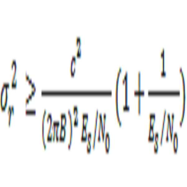
이것은 실내 레인징에서 사용될 것으로 예상된 전형적 신호-대-잡음 비에 대해서이다.This is for a typical signal-to-noise ratio expected to be used in indoor ranging.
우리는, 공식으로부터, 신호 대역폭(BW)을 증가시키든지 또는 우리의 신호에 대한 신호 SNR을 증가시키든지 또는 양자에 의해, 
일 실시형태에서, 모바일은 신호 BW을 증가시키도록, 펄스 윈도잉 있는 또는 없는, 주파수 변조, 선형 및 비-선형 양자의 스윕 방법을 사용한다. 동일한 SNR을 고려하면, 주파수 변조는 시간에서 1/BW 그리고 거리에서 2c/BW만큼 레인지 분해능을 증가시킬 수 있다. 선형 주파수 변조(LFM)는 일부 레이더 시스템에서 사용된 기술이다. 여기에서 개시된 반사기에 대해, 주파수를 변화시키는 것은 반사기에서의 지향성의 각도를 변화시키는 것임을 주목하라. 이러한 이유로, 주파수 스윕 범위(BW)는 이러한 실시형태에서는 반사기의 지향성이 거의 변하지 않는 BW로 한정된다. 그리하여, 이러한 실시형태에서, 신호의 중심 주파수를 변화시키는 것은 다른 반사기 지향성 각도를 초래한다. 그러나, LFM의 경우에서와 같이 더 작은 BW만큼 중심 주파수 주위 주파수를 변화시키는 것은 경미한 지향성 변화를 초래하여 LFM 스윕 동안 재귀-지향성이 보존됨을 보증한다. LFM 주파수 변조는 일 실시형태에서 사용된다. 그러나, LFM 대신에 비-선형 주파수 변조, 윈도잉된 주파수 변조, 게이팅된 LFM, 업 스윕 및 다운 스윕 LFM은 물론 스텝핑된 처프 파형(예컨대, "Fundamentals of Radar Signal Processing" 참조)을 포함하는 많은 다른 주파수 변조도 사용될 수 있다.In one embodiment, the mobile uses a frequency modulation, linear and non-linear sweep method with or without pulse windowing to increase the signal BW. Considering the same SNR, the frequency modulation can increase the range resolution by 1 / BW in time and 2c / BW in distance. Linear frequency modulation (LFM) is a technique used in some radar systems. Note that for the reflectors disclosed herein, changing the frequency is to change the angle of the directivity at the reflector. For this reason, the frequency sweep range BW is limited to the BW in which the directivity of the reflector hardly changes in this embodiment. Thus, in this embodiment, changing the center frequency of the signal results in a different reflector directivity angle. However, changing the frequency around the center frequency by a smaller BW, as in the case of the LFM, results in a slight directional change, ensuring that the recursive-directionality is preserved during the LFM sweep. LFM frequency modulation is used in one embodiment. However, there are many other techniques, including non-linear frequency modulation, windowed frequency modulation, gated LFM, upsweep and downsweep LFM, as well as stepped chirp waveforms (e.g., see Fundamentals of Radar Signal Processing) Frequency modulation can also be used.
일 실시형태에서, 주파수 변조를 사용하는 공동-위치하는 모바일 디바이스는 그들 레이더 신호를 인근 다른 모바일 디바이스와 구별하도록 반사기에 의해 좌우되는 바와 같은 다른 중심 주파수, 상이한 게이팅 온/오프 시간, 및 다른 스윕 레이트를 선택할 수 있다.In one embodiment, the co-located mobile devices using frequency modulation may use different center frequencies, different gating on / off times, and other sweep rates as are dependent on the reflector to distinguish their radar signals from nearby other mobile devices Can be selected.
일 실시형태에서는, 위상 변조된 신호가 사용된다. 예시적 위상 변조는 BPSK 또는 QPSK 유형을 포함한다. 반송파는 신호 대역폭(BW)을 증가시키도록 직접 시퀀스 확산 스펙트럼(DSSS)을 사용하여 변조된다. 이러한 실시형태에서 DSSS는 2개의 목적을 제공한다. 그것은 BW를 증가시키고 그리하여 CRLB에 따라 레인지 측정 정확도를 개선한다. 그것은 또한 다중-액세스 능력을 제공한다. 다중-액세스는 쇼핑 센터 및 스포츠 이벤트에서의 경우와 같은 동일한 부근 내 수많은 모바일 디바이스를 지원할 수 있는 능력을 지칭한다. 이러한 다중 액세스는 여러 다른 위성 신호 간을 구별하도록 GPS에서 현재 채용되는 바와 같이 여러 다른 의사 난수 시퀀스(PRN)를 사용함으로써, 또는 동일한 주파수 상에서 여러 다른 모바일 및 셀 사이트를 분리하도록 CDMA 통신 시스템에서 오늘날 사용되는 바와 같이, 동일한 PRN을 사용하지만 어느 예상된 반사 지연보다도 더 큰 PRN 오프셋만큼 사용자를 분리함으로써 달성될 수 있다(예컨대, "CDMA RF Systems Engineering", Samuel C. Yang, 1998년 참조). In one embodiment, a phase modulated signal is used. Exemplary phase modulation includes BPSK or QPSK types. The carrier is modulated using a direct sequence spread spectrum (DSSS) to increase the signal bandwidth (BW). In this embodiment the DSSS provides two objectives. It increases the BW and thus improves the range measurement accuracy according to the CRLB. It also provides multi-access capability. Multi-access refers to the ability to support numerous mobile devices in the same vicinity, such as in shopping centers and sporting events. These multiple accesses can be used today in CDMA communication systems by using different pseudorandom sequence sequences (PRN) as currently employed in GPS to distinguish between different satellite signals, or to separate several different mobile and cell sites on the same frequency (See, e. G., &Quot; CDMA RF Systems Engineering ", Samuel C. Yang, 1998) using the same PRN but separating the user by a PRN offset greater than any expected reflection delay.
일 실시형태에서, 의사 난수(PRN) 시퀀스를 사용하는 대신에, 모바일은 참 난수(TRN) 시퀀스를 사용한다. PRN 시퀀스는 그것들이 실제로는 랜덤이 아니고 참 난수 시퀀스를 가능한 많이 흉내내는 시퀀스를 산출하도록 설계된 수학적 관계에 따라 발생되기 때문에 소위 의사 랜덤이다.In one embodiment, instead of using a pseudo-random number (PRN) sequence, the mobile uses a true random number (TRN) sequence. The PRN sequences are so-called pseudo-random because they are not actually random and are generated according to a mathematical relationship designed to produce sequences that mimic as many random sequences as possible.
참 랜덤인 TRN은 정의에 의해 무한 사이클 길이를 갖는다. 그것들은, 증폭된 열 잡음, 또는 다이오드 역방향 바이어싱된 사태 잡음과 같은, 자연적으로 일어나는 랜덤 현상을 디지털화함으로써 모바일 내에서 온 더 플라이 발생될 수 있다. 그러한 TRN은 이론적으로는 다른 TRN과 영 상호 상관을 가지고 그리하여 그것들을 사용하여 코딩된 신호는 실제로 모든 다른 리스너에게 또는 하나 이상의 칩 주기만큼 시간에서 시프트된 자신의 어느 사본에라도 더 높은 열 잡음처럼 보인다. 반사기의 수동 및 선형 본성을 고려하면 동일한 디바이스에서 Tx 프로세싱 및 Rx 프로세싱 양자가 수행되므로 TRN을 사용하는 것이 가능하다. Tx 및 Rx가 동일한 디바이스 상에서 일어나면, TX 신호를 발생시키는데 사용된 참 난수 시퀀스 값의 일시적 사본을 이들 값이 Rx에서의 반사를 상관 또는 디-스프레딩하는데 사용될 때까지 유지함으로써 TRN 사용이 행해진다. 레인징 신호의 발신자가 수신자로부터 물리적으로 떨어져 있는 경우 모든 다른 이전에 제안된 실내 솔루션은 실시간으로 TRN을 사용할 수 없을 것이다. 이것은 적분 시간에 대한 어떠한 한계도 제거하고 그리고 모바일이 그것이 소정 순간에 소망하는 정확도를 그것이 이루는데 필요한 어떤 적분 시간이라도 선택할 수 있게 한다.The true random TRN has an infinite cycle length by definition. They can be generated on-the-fly in the mobile by digitizing naturally occurring random phenomena, such as amplified thermal noise, or diode reverse biased incident noise. Such a TRN theoretically has zero correlation with other TRNs so that the signal coded using them looks like a higher thermal noise to any other listener or to any copy of itself shifted in time by one or more chip periods. Considering the passive and linear nature of the reflector, it is possible to use TRN because both Tx processing and Rx processing are performed in the same device. If Tx and Rx occur on the same device, TRN usage is made by keeping a temporary copy of the true random sequence value used to generate the TX signal until these values are used to correlate or de-spread the reflections at Rx. If the originator of the ranging signal is physically separated from the receiver, all other previously proposed indoor solutions will not be able to use the TRN in real time. This eliminates any limit to the integration time and allows the mobile to select any integration time it needs to achieve the accuracy it desires at a given moment.
Rx 및 Tx 양자가 동일한 모바일 상에 거처하고 동일한 국부 발진기를 사용하기 때문에 모바일 클록이 유효 신호 상관을 위해 외부 소스와 절대 시간으로 동기화될 필요는 없더라도, 그렇지만 모바일 클록은 소망의 레인지 정확도를 내놓도록 광속으로 반사 비행 시간을 타이밍하기에 충분히 정확해야 한다. 환언하면, 모바일 클록이 절대 세계 시간을 유지하는 것이 중요하지는 않지만, 국부 모바일 클록은 Tx로부터 Rx 반사까지의 시간을 정확하게 측정하여야 한다. 클록이 정확한 차분 시간(Rx_시간 - Tx_시간)을 유지함을 보증하는 것은 국부 모바일 클록이 절대 시간을 정확하게 유지함을 보증하는 것보다 훨씬 더 간단한 문제이다. 일 실시형태에서, 모바일은 정확한 참조로부터 유도된다고 알려져 있는 그리고 이러한 소스가 도플러에 기인하여 그 겉보기 주파수를 시프트하지 않도록 이동하고 있지 않는 환경에서 이용가능한 어느 현재의 RF 신호에라도 국부 발진기를 로킹함으로써 정확한 차분 시간을 유지하도록 이루어진다. 실내 환경에 대해, 사용자 이동은 가장 엄격한 애플리케이션을 제외하고는 수락가능한 사용자 이동에 기인하는 도플러를 무시하기에 충분히 느리다. 매우 정확한 주파수 참조를 갖는 외부 정지 참조 소스의 예는 브로드캐스트 라디오 또는 TV 신호 또는 어느 셀룰러 네트워크라도 포함하며, 비동기식 네트워크를 포함한다. 실제로, CDMA 및 LTE와 같은, 모든 현대 셀룰러 모바일 폰은 이미 그것을 행하여 모바일과 셀 사이트 간 적절한 통신을 가능하게 한다. 셀룰러 네트워크 신호에 국부 발진기의 이러한 로킹은 또한 일부 실외 위치 측위 구현에서 더 긴 GPS 신호 상관 시간이 가능하도록 사용되어 왔다. 국부 발진기가 예컨대 셀 사이트 파일럿 신호에 로킹되고 나면, 국부 발진기 주기는 셀 사이트에서 검출된 GPS 콘스텔레이션의 그것과 같게 조절된다. 사실상, 이러한 동작은 비교적 저렴한 국부 발진기가 GPS 시간처럼 정확한 "스톱 워치" 정확도를 유지할 수 있게 하고, 그리하여 매우 높은 정확도 레인지 측정을 달성한다. 발진기 로킹 후에라도, 모바일 디바이스의 절대 시간은 미지의 모바일 대 셀 사이트 전파 지연만큼 절대 시간과 다를 수 있다. 다행히도, 외부 데이터에 따른 절대 시간은 반사기의 수동 본성에 기인하여 필요하지 않다. 이러한 기술은 오늘날의 실내 환경에서 유비쿼터스 셀룰러 커버리지 때문에 실내에서 작동한다. 외부 참조에 발진기를 로킹하는 것은 매우 높은 위치 정확도가 소망될 때 수행될 수 있다. 다른 애플리케이션에서, 수정-기반 국부 참조 발진기는 충분한 정확도를 갖는다. Although the mobile clock does not need to be synchronized to absolute time with an external source for valid signal correlation because both Rx and Tx reside on the same mobile and use the same local oscillator, the mobile clock, however, Should be accurate enough to timing the reflex flight time. In other words, although it is not important that the mobile clock maintain absolute world time, the local mobile clock must accurately measure the time from Tx to Rx reflex. Ensuring that the clock maintains the correct differential time (Rx_time - Tx_time) is a much simpler problem than ensuring that the local mobile clock keeps the absolute time accurate. In one embodiment, the mobile is configured to lock the local oscillator to any current RF signal that is known to be derived from an accurate reference, and which is available in an environment where such source is not shifting due to Doppler shifts its apparent frequency, Time is maintained. For indoor environments, user movement is slow enough to ignore Doppler due to acceptable user movement except for the most stringent applications. Examples of external stop reference sources with highly accurate frequency references include broadcast radio or TV signals or any cellular network, including asynchronous networks. Indeed, all modern cellular mobile phones, such as CDMA and LTE, already do so to enable proper communication between mobile and cell sites. This locking of the local oscillator to the cellular network signal has also been used to enable longer GPS signal correlation times in some outdoor location positioning implementations. Once the local oscillator is locked, for example, to the cell site pilot signal, the local oscillator period is adjusted to be equal to that of the GPS constellation detected at the cell site. In effect, this operation allows a relatively inexpensive local oscillator to maintain accurate "stopwatch" accuracy as GPS time, thus achieving very high accuracy range measurements. Even after oscillator locking, the absolute time of the mobile device may be different from the absolute time by the unknown mobile-to-cell site propagation delay. Fortunately, the absolute time due to external data is not necessary due to the passive nature of the reflector. These techniques work indoors because of ubiquitous cellular coverage in today's indoor environments. Locking the oscillator to an external reference can be performed when very high positional accuracy is desired. In other applications, the correction-based local reference oscillator has sufficient accuracy.
일 실시형태에서 위상 변조가 사용될 때 소정 반사기 내 내장 지연은 단일 PRN 또는 TRN 칩 주기보다 더 커야 함을 여기에서 주목하는 것이 중요하다. 이것은 실내 환경에서는 전형적 칩핑 레이트에서 단일 칩 주기 동안 주행한 거리가 조우한 측정된 레인지보다 훨씬 더 길 것이라고 예상되기 때문이다. 예컨대, 10MHz 칩핑 레이트에서, 거리에서의 칩 길이는 자유 대기에서 약 30 미터이다. 그것은 모두 단일 코드 칩 내에서 신호가 모바일 TX를 빠져나가고, 반사기로 주행하고 그리고 모바일 Rx로 되돌아 올 고도의 개연성이 있음을 의미한다. 이것은 모바일이 동일한 모바일로부터의 Tx 신호와 그 에코 Rx 신호 간을 구별하기 위해 반사기 내장 지연이 하나의 칩보다 더 클 필요가 있음을 의미한다. 더욱, 반사를 부근에서의 다양한 반사로부터 분리하기 위해, 모든 반사기마다 최소 하나의 코드 칩 주기, 예컨대, 10MHz 칩핑 레이트에 대해 100ns만큼 모든 다른 반사기와는 다른 지연을 가져야 한다. 이것은 일 실시형태에서는 단순 BAW 필터로 용이하게 성취될 수 있다. 또한, 반사기가 부분 반사를 채용하는 구현에서, 반사기 지연은 근거리의 반사기로부터의 이차 반사가 더 긴 내장 지연을 갖는 원거리의 반사기의 PRN 지연과 정합하는 것을 방지하기 위해 소정 반사기로부터 다수의 부분 전력 반사가 잦아들 수 있게 하도록 하나의 주기보다 많이 서로 달라야 한다.It is important to note here that the built-in delay in a given reflector when phase modulation is used in one embodiment must be greater than a single PRN or TRN chip period. This is because it is expected that the distance traveled during a single chip period at a typical chipping rate in an indoor environment will be much longer than the measured range encountered. For example, at a 10 MHz chipping rate, the chip length at distance is about 30 meters in the free atmosphere. It all means that within a single code chip, there is a high likelihood that a signal will pass through the mobile TX, travel to the reflector, and return to the mobile Rx. This implies that the reflector built-in delay needs to be larger than one chip in order for the mobile to distinguish between the Tx signal from the same mobile and its echo Rx signal. Furthermore, in order to separate the reflections from the various reflections in the vicinity, there should be a delay different from all other reflectors by at least one code chip period for every reflector, e.g., 100 ns for a 10 MHz chipping rate. This can be easily accomplished with a simple BAW filter in one embodiment. Also, in an implementation in which the reflector employs partial reflection, the reflector delay may be adjusted such that the secondary reflection from a nearby reflector does not match the PRN delay of the far-field reflector with a longer built-in delay, Should be different from one cycle to allow them to be idle.
여기에서 개시된 시스템은 실내 위치 측위에 대해 비컨 및 의사 위성에 의해 경험된 근거리/원거리 문제에 무감할 수 있다. 이것은 대부분의 시간에 여러 다른 반사기로부터의 반사는 반사기 주파수 각도 스윕 특징에 기인하여 다른 중심 주파수에서 일어나고 그리하여 주파수 베이스에 기반하여 격리될 수 있기 때문이다. 부가적으로, 긴 PRN은 물론 이론상 무한 사이클 TRN도 사용할 수 있는 능력은 그러한 코드에 대한 낮은 상호 상관 값에 기인하여 근거리/원거리의 자신의 반사 신호의 더 양호한 분리가 가능하다. 긴 PRN 또는 TRN은 동일한 국부 발진기가 발진기 위상 잡음의 한계까지 신호를 디스프레딩하는 것 및 스프레딩하는 것 양자에 사용된다는 사실에 의해 실현가능하게 된다. 더욱, 매우 정체된 조건 하에서, 중앙 네트워크 라디오 링크 관리자는 용인할 수 없는 상호 간섭이 일어나지 않음을 보증하도록 모바일들 간을 조정할 수 있다. 이러한 관리자는 인터넷 클라우드에 어딘가에 거처할 수 있다. 이것은 반사기가, 방사 비컨 또는 의사 위성과는 대조적으로, 수동이고 그리하여 부근에서의 모바일로부터 유래하는 신호만을 방사할 뿐이기 때문에 가능하다. 라디오 링크 관리자는 관리가능한 수의 모바일 동시-액세스만이 부근에서의 반사기를 사용할 수 있게 하여 소망의 또는 달성가능한 레벨의 정확도로 모두에 대해 유용한 위치 측위 결정을 보증할 수 있다. 시스템은 모바일이 하나의 근거리의 반사기를 사용하여 그 위치를 결정할 수 있기 때문에 다른 시스템의 근거리/원거리 문제에 매우 무감할 수 있다. 검출된 부가적 원거리의 반사기는 정확도를 개선하지만 유용한 3D 위치 결정에 필요하지는 않다. 그래서, 있을 것 같지는 않지만 모바일이 동일한 중심 주파수에서의 2개의 반사기로부터의 반사를 수신하며 하나의 반사가 다른 것보다 훨씬 더 높은 전력을 갖는 경우에, 아마 하나의 반사기를 보고 있을 모바일은 여전히 그 위치를 유용하게 계산할 수 있고 그리고, 단시간에, 작은 이동은 안테나 스윕 중심 주파수를 변화시켜 모바일이 다른 반사기를 검출하고 그리하여 이전 위치 결정을 정제할 수 있게 한다. The system disclosed herein may be insensitive to local / remote problems experienced by beacons and pseudolites for indoor positioning. This is because reflections from different reflectors at most times occur at different center frequencies due to the reflector frequency angular sweep feature and thus can be isolated based on the frequency base. In addition, the ability to use the long PRN as well as the theoretically infinite cycle TRN allows for better separation of its near / far reflected signal due to the low cross-correlation value for such code. The long PRN or TRN becomes feasible due to the fact that the same local oscillator is used for both spreading and spreading the signal to the limit of the oscillator phase noise. Moreover, under very congested conditions, the central network radio link manager can coordinate between mobiles to insure that unacceptable mutual interference does not occur. These administrators can reside somewhere in the Internet cloud. This is possible because the reflector is only passive and therefore radiates only the signal originating from the mobile in the vicinity, in contrast to the emission beacon or pseudo-satellite. The radio link manager can ensure that only a manageable number of mobile concurrent-accesses can use the reflectors in the vicinity to make position location determination that is useful for both with a desired or achievable level of accuracy. The system can be very insensitive to the near / far problems of other systems because the mobile can determine its location using a single near-field reflector. The detected additional remote reflectors improve the accuracy but are not required for useful 3D positioning. So, while it is unlikely that a mobile receives reflections from two reflectors at the same center frequency and one reflex has a much higher power than the other, the mobile that is probably looking at one reflector is still at that location And in a short period of time a small shift changes the antenna sweep center frequency so that the mobile can detect another reflector and thus refine the previous positioning.
일 실시형태에서, 다른 반사기를 마스킹하는 근거리의 반사기에 대한 매우 강력한 반사를 수신하는 모바일은 모바일의 방향으로 최대 반사를 초래하는 최적으로부터 송신 주파수를 디튜닝함으로써 이러한 근거리의 반사기로부터의 반사 전력을 감축할 수 있다. 이것은 근거리의 반사기로부터의 반사 전력을 심하게 저하시켜 모바일이 훨씬 더 낮은 반사 전력을 갖는 원거리의 반사기로부터의 신호를 검출할 수 있게 할 수 있다. 모바일은 또한 근거리/원거리 현상에 기인하는 필요한 Rx 동적 레인지를 감축하도록 다른 반사기를 여기시키는 각각의 중심 주파수에 대한 별개의 전력 제어를 수행할 수 있다. In one embodiment, a mobile receiving very strong reflections to a near-field reflector that masks another reflector may reduce the reflected power from such near-field reflectors by subtracting the transmit frequency from the best resulting in maximum reflection in the direction of the mobile can do. This can severely reduce the reflected power from the near-field reflectors so that the mobile can detect signals from the far-field reflectors with much lower reflected power. The mobile may also perform separate power control for each center frequency that excites the other reflectors to reduce the required Rx dynamic range due to near / far phenomena.
사택 내에서와 같이, 단일 사용자 또는 낮은 수의 띄엄띄엄 위치 결정 사용자를 갖는다고 예상되는 장소에서, 레이더 신호의 위상 변조에 대한 일차적 목적은 오로지 모바일과 반사기 간 더 미세한 레인지 분해능을 초래하도록 신호 대역폭(BW)을 증가시키는 것이다. 그러한 시나리오 하에서, 그리고 일 실시형태에서, 모바일은 베이커 코드 또는 시프트된 베이커 코드의 적 또는 어느 수의 다른 코드와 같은 비교적 짧은 PRN 코드를 채용할 수 있다(예컨대, "Fundamentals of Radar Signal Processing" 4.10절 참조). 여기에서 소망의 BW 증가는 PRN 시퀀스 길이가 아니라 칩 레이트의 결과이다. 그리하여, 이들 시퀀스가 짧더라도, 여전히 BW 증가를, 그리하여, 대략 1/BW의 칩핑 레이트만큼, 레인지 분해능 개선을 이룰 수 있다. 낮은 수의 사용자를 고려하면, 정확도를 증가시키기 위한 SNR 개선은 인접 사용자의 확률이 낮으므로 출력 전력을 증가시킴으로써 행해질 수 있다. 그래도, 이들 띄엄띄엄한 환경에 대해서도, SNR을 개선하는데 더 긴 코드가 여전히 사용될 수 있다. In places where it is expected to have a single user or a low number of spatially positioned users, such as within a premises, the primary purpose for phase modulation of the radar signal is to reduce the signal bandwidth BW). Under such a scenario, and in one embodiment, the mobile may employ a relatively short PRN code, such as Baker code or an enemy or any number of other codes of shifted Baker code (e.g., "Fundamentals of Radar Signal Processing" Reference). Where the desired BW increase is the result of the chip rate rather than the PRN sequence length. Thus, even if these sequences are short, the range resolution improvement can still be achieved by a BW increase, and thus by a chipping rate of approximately 1 / BW. Considering a low number of users, the SNR improvement to increase the accuracy can be done by increasing the output power because the probability of the neighboring users is low. Still, even for these sparsely populated environments, longer code can still be used to improve SNR.
일 실시형태에서, 수많은 모바일 디바이스가 서로 가까운 근처 내에서 그들 위치를 결정하려고 시도할 것으로 예상되는 장소에서는, 더 긴 PRN 시퀀스 또는 심지어 TRN 시퀀스가 사용된다. 더 긴 시퀀스로 2개의 시스템 아키텍처는 자신들을 제시한다. 제1 아키텍처는 동시 TX 및 RX가 동일한 모바일 내에서 일어나는 것이 가능하지 않다(하프 듀플렉스). 제2의 것은 동시에 동시 TX 및 Rx가 가능하다(풀 듀플렉스). 레이더 시스템에서는 전통적으로 하프 듀플렉스가 유리하였다. 이것은 레이더 시스템에서는 수신 신호가 송신 신호의 지연된 사본이기 때문이다. 그리하여, 단순 대역 분리를 사용하는 Tx와 Rx 간 전형적 채널 분리는 실용적이지 않을 수 있다. 그래서, 지금까지의 대다수의 레이더 시스템에 대해, Tx와 Rx 활동은 시간 인터리빙되어 Rx는 Rx 경로로 되돌아 누설되는 Tx 신호에 의해 압도되게 되지 않는다. In one embodiment, a longer PRN sequence, or even a TRN sequence, is used where a number of mobile devices are expected to attempt to determine their location within close proximity to each other. The two system architectures present themselves in a longer sequence. The first architecture is not possible for concurrent TX and RX to occur within the same mobile (half duplex). The second is simultaneous TX and Rx capable (full duplex) at the same time. Traditionally, half duplex has been advantageous in radar systems. This is because in the radar system the received signal is a delayed copy of the transmitted signal. Thus, typical channel separation between Tx and Rx using simple band separation may not be practical. So, for most radar systems to date, Tx and Rx activity is time interleaved so that Rx is not overwhelmed by the Tx signal leaking back to the Rx path.
일 실시형태에서, 모바일 디바이스는 송신 레이더 신호의 위상을 변조하는데 긴 PRN 또는 TRN을 사용하고 Tx와 Rx 활동을 시간 인터리빙한다. PRN 시퀀스의 이점을 충분히 얻기 위해서는 적어도 하나의 완전 PRN 시퀀스 길이를 발신하여야 한다. 그 시간 동안 Rx측은 마스킹 오프 된다. Tx와 Rx가 중첩하지 않기 위해, 2개의 대안 중 어느 하나가 채용된다. 제1의 것은 반사기에 채용된 내장 지연이 하나의 완전 길이의 PRN 시퀀스에 부응하기에 충분히 길게 되는 것이다. 환언하면, 완전 길이의 PRN이 송신되는 동안 반사는 되돌려 발신되지 않고, 그 후에 Tx는 오프로 되고 그리고 Rx는 반사를 수신하기 직전에 가능으로 된다. 다른 대안은 단일 PRN 시퀀스 길이 내에서 Tx와 Rx 활동을 시간 인터리빙하는 것이다. 예컨대, Tx가 온으로 되고 PRN 시퀀스 길이의 일부를 송신하고 그 후 Tx를 오프로 하고 Rx를 가능으로 하여 반사의 에코를 경청한다. 예상된 반사의 기간 후에, Tx는 온으로 되어 PRN 시퀀스의 다른 일부를 송신하는 한편 Rx는 불능으로 되고 등이다. 이러한 인터리빙은 PRN 총 시퀀스 길이가 송신될 때까지 계속된다. 이러한 인터리빙은 내장 반사기 지연이 크지 않게 하는 결과를 갖지만 동시에 긴 PRN 시퀀스의 이점을 보존한다. 양 대안에서, 제1 칩을 발신하는 것과 시퀀스에서의 마지막 칩을 수신하는 것 간 기간은 이론적으로는 동일하다. 그렇지만, 부분 인터리빙의 경우에는, Tx와 Rx 스위칭 간 소정 가드 타임이 반사기의 가변 지연에 부가하여 고려되어야 한다. In one embodiment, the mobile device uses a long PRN or TRN to modulate the phase of the transmitted radar signal and time interleaves the Tx and Rx activity. In order to fully benefit from the PRN sequence, at least one full PRN sequence length should be originated. During that time, the Rx side is masked off. In order that Tx and Rx do not overlap, either of the two alternatives is employed. The first is that the built-in delay employed in the reflector is long enough to accommodate one full-length PRN sequence. In other words, while the full length PRN is being transmitted, the reflections are not sent back, after which Tx is off and Rx is enabled just before receiving the reflections. Another alternative is to time interleave Tx and Rx activities within a single PRN sequence length. For example, Tx is turned on, a portion of the PRN sequence length is transmitted, and then Tx is turned off and Rx is enabled to listen to the echo of the reflection. After the expected period of reflection, Tx is turned on to transmit another portion of the PRN sequence while Rx is disabled and so on. This interleaving continues until the PRN total sequence length is transmitted. This interleaving results in less intrinsic reflector delay but at the same time preserves the advantages of the long PRN sequence. In both alternatives, the period between sending the first chip and receiving the last chip in the sequence is theoretically the same. However, in the case of partial interleaving, the predetermined guard time between Tx and Rx switching must be considered in addition to the variable delay of the reflector.
다른 실시형태에서, Tx와 Rx 양자는 동시에 일어난다(풀 듀플렉스). 레이더 시스템에서, Rx 경로를 스플래싱하는 Tx 신호는 그것이 동일한 모바일 내에서 구축되므로 큰 정확도로 알려져 있다. 그러한 시나리오 하에서, 능동 잡음 소거 기술은 결합된 그리고 바람직하지 않은 Tx 스플래싱을 감산해 내도록 Rx 신호 경로 상에서 사용될 수 있다. 예컨대, 서큘레이터(circulator), 교차 안테나 편파 및 능동 잡음 소거가 사용될 수 있다. 이것은 유용한 실내 위치 측위에 충분한 동적 레인지를 준다. 모든 반사기가 최소 하나의 코드 칩 지연을 갖는다는 사실은 환경으로부터의 가까운 반사가 디스프레딩 Rx 동작에 의해 감쇠될 수 있음을 의미한다. 또한, 긴 PRN 또는 TRN 코드의 사용은 이러한 격리 요건을 개선하도록 더 높은 프로세싱 이득이 가능하고 그리고 더욱 모바일과 반사기 간 느린 상대 운동에 기인하여 무시할 수 있는 상대적 도플러 시프트에 기인하는 무시할 수 있는 상호 상관에 의해 가능하게 된다. 반사기의 재귀-지향성 속성에 기인하여, 레이더 반사는 전형적 레이더 애플리케이션에서보다 훨씬 더 강력하고 그리하여 더 낮은 동적 레인지가 요구되어 더 적은 필요한 Tx/Rx 격리를 초래함을 주목한다. In another embodiment, both Tx and Rx occur simultaneously (full duplex). In a radar system, the Tx signal that spans the Rx path is known to be of great accuracy since it is built in the same mobile. Under such scenarios, the active noise cancellation technique may be used on the Rx signal path to subtract the combined and undesired Tx splashing. For example, a circulator, cross-antenna polarization, and active noise cancellation may be used. This gives sufficient dynamic range for useful indoor positioning. The fact that all reflectors have at least one code chip delay means that near reflections from the environment can be attenuated by the despreading Rx operation. In addition, the use of long PRN or TRN codes has been found to be advantageous for negligible crosscorrelation due to the relatively high processing gain possible to improve this isolation requirement and also due to the relative Doppler shift negligible due to slow relative motion between the mobile and reflector . Note that due to the recursive-directivity properties of the reflector, the radar reflection is much stronger than in a typical radar application and thus a lower dynamic range is required resulting in less required Tx / Rx isolation.
BW을 증가시키기 위해서도 그리고/또는 다양한 다중-액세스 동작을 가능하게 하기 위해서도 신호를 변조하는 다양한 실시형태에 부가하여, 우리는 또한 CRLB 식에서 서술된 바와 같이 SNR 비를 증가시킴으로써 레인지 분해능을 개선할 수 있다. SNR을 증가시키는 것은 2개의 방식으로 행해진다. 일 실시형태에서, SNR은 모바일로부터의 레이더 신호에 대한 평균 송신 전력을 증가시킴으로써 증가된다. 이것은 배터리 전력 소비가 엄청나게 될 때 소정 대역에 대해 모바일 디바이스로부터의 최대 방사 전력에 대한 FCC 한계에 도달될 때까지 행해질 수 있다. 다른 실시형태에서, Rx 상관 시간이 증가되고 그리하여 Rx의 프로세싱 이득을 증가시키고 등가 SNR을 개선한다. 증가된 상관 시간은 주파수 및 주기 정확도를 위해 Tx와 Rx 마스터 클록 간 타이트 동기화를 필요로 한다. 다행히도, 여기에서 개시된 시스템은 수동 반사기를 사용하고 그리하여 Tx 및 Rx 신호 양자는 동일한 모바일 내에서 동일한 클록을 사용한다. 그러한 상황 하에서, 상관 시간은 전형적으로 마이크로초 차수의, 반사기 내장 지연을 포함하는, 반사 왕복 지연에 걸리는 시간 동안 국부 클록이 얼마나 많이 드리프트하는지에 의해서만 제한될 뿐이고, 그리하여 상관 시간은 저렴한 발진기에 대해서도 무한일 수 있다. 코히어런트 상관 시간이 더 길수록, 프로세싱 이득이 더 높고 그리하여 달성된 SNR이 더 높다. 이것의 일례는 수신 신호가 전형적으로 열 잡음 바닥 대비 -25dB이지만 수신기가 긴 상관 시간을 사용하는 프로세싱 이득에 기인하여 신호를 검출 및 프로세싱할 수 있는 GPS에서 일어나는 것이다.In addition to various embodiments of increasing the BW and / or modulating the signal to enable various multi-access operations, we can also improve the range resolution by increasing the SNR ratio as described in the CRLB equation . Increasing the SNR is done in two ways. In one embodiment, the SNR is increased by increasing the average transmit power for the radar signal from the mobile. This can be done until the FCC limit for the maximum radiated power from the mobile device for a given band is reached when battery power consumption is enormous. In another embodiment, the Rx correlation time is increased, thereby increasing the processing gain of Rx and improving the equivalent SNR. The increased correlation time requires tight synchronization between Tx and Rx master clocks for frequency and period accuracy. Fortunately, the system disclosed herein uses a passive reflector so that both the Tx and Rx signals use the same clock within the same mobile. Under such circumstances, the correlation time is only limited by how much the local clock drifts during the time it takes for the round trip delay, including the reflector built-in delay, of microsecond order, so that the correlation time is also infinite Lt; / RTI > The longer the coherent correlation time, the higher the processing gain and thus the higher the achieved SNR. An example of this is what happens in a GPS where the received signal is typically -25dB versus a thermal noise floor but the receiver can detect and process the signal due to the processing gain using long correlation times.
GPS에서, 방출된 DSSS 위상 변조된 반송파는 필터링되지 않고 그리하여 스펙트럼은 반송파 주파수의 좌측으로 그리고 우측으로 무한히 뻗는 SINC 함수에 근사한다. GPS는 해수면에서의 수신 신호 전력이 자연 열 잡음 레벨의 약 25dB 아래이므로 이것을 행할 수 있다. 지상 통신에 대해, 전력 레벨은 더 높고 그리고 대역 외 방출은 필터링되어야 한다. 그래서, 전형적 지상 DSSS 송신은 송신 BW 내에서 평탄한 스펙트럼 전력 레벨을 그리고 그 BW 바깥에서 매우 낮은 방출을 갖는다. 반사기의 주파수 스윕 본성을 고려하면 우리는 반사 신호가 송신 BW 내에서 평탄하지 않은 스펙트럼을 갖는다고 예상할 것이다. 이것은 주파수가 모바일의 방향으로 최대 반사를 주는 주파수로부터 멀어지게 됨에 따라 반사기의 이득이 떨어지기 때문이다. 모바일이 송신 신호의 중심 주파수가 모바일의 방향으로의 최대 반사에 필요한 바로 그 주파수인 DSSS를 송신하고 있다고 가정하면, 그때는 반사 신호의 스펙트럼이 평탄하지 않을 것이지만 우리가 중심으로부터 어느 일측으로 멀어지게 됨에 따라 동등하게 전력이 떨어질 것이라고 예상할 것이다. 송신 신호가 모바일의 방향으로의 최적 반사에 필요한 주파수보다 조금 더 높거나 낮은 중심 주파수를 가지면, 그때 그 피크 전력은 BW의 중심으로부터 일측 또는 타측으로 오프셋될 것이다. 이것은 그것이 그 중심 주파수를 조절하여야 한다는, 그리고, 모바일의 방향으로 소정 반사기에 대한 최대 반사에 필요한 주파수 및 그리하여 조절된 중심 주파수 주위의 대칭적 반사 스펙트럼 전력을 추적하기 위해, 어느 방향으로인지의 표시를 모바일에 제공한다. 그것은 또한 주파수를 연속적으로 스윕할 필요 없이 AOA에 대한 표시를 제공한다.In GPS, the emitted DSSS phase modulated carrier is not filtered, so the spectrum approximates a SINC function that extends infinitely to the left and right of the carrier frequency. GPS can do this because the received signal power at sea level is below about 25 dB below the natural thermal noise level. For terrestrial communications, the power level is higher and out-of-band emissions must be filtered. Thus, a typical terrestrial DSSS transmission has a flat spectral power level within the transmit BW and a very low emission outside that BW. Considering the frequency sweep nature of the reflector, we will expect that the reflected signal has an uneven spectrum within the transmitted BW. This is because the reflector's gain drops as the frequency moves away from the frequency that gives the maximum reflection in the direction of the mobile. Assuming that the mobile is transmitting the DSSS, the center frequency of the transmitted signal, which is the very frequency required for maximum reflection in the direction of the mobile, then the spectrum of the reflected signal will not be flat, but we will move away from the center You will expect that the power will drop equally. If the transmitted signal has a center frequency that is slightly higher or lower than the frequency required for optimal reflection in the direction of the mobile, then the peak power will be offset from the center of BW to one side or the other. This indicates an indication of which direction it should be to adjust its center frequency and to track the symmetrical reflection spectral power around the center frequency and thus the frequency required for maximum reflection for a given reflector in the direction of the mobile Mobile. It also provides an indication of AOA without having to continuously sweep the frequency.
일 실시형태에서, 모바일은 다양한 레벨의 정확도를 달성하도록 그것이 이용하는 수고를 증가 또는 감소시키기에 충분히 융통성 있다. 우리가 앞서 서술한 바와 같이, 증가된 정확도는 신호 BW, 송신 전력 레벨 및 코히어런트 Rx 상관 시간 중 어느 것 또는 전부를 증가시키는 것을 요구한다. 증가된 BW는 신호의 일부가 모바일의 방향으로 더 낮은 반사기 안테나 이득을 경험하며 신호의 일부가 모바일로부터 떨어져 반사되고 그리하여 부근에서의 다른 모바일에 대한 간섭을 증가시키는 결과를 초래한다. 송신 전력을 증가시키는 것은 배터리 수명을 감축하고 그리고 또한 다른 것들에 대한 간섭을 증가시킨다. 마지막으로, 상관 시간을 증가시키는 것은 또한 배터리 수명을 감소시키고 그리고 더 긴 송신 신호 듀레이션(duration)에 기인하여 다른 것들에 대한 배경 잡음을 증가시키고 더 긴 고정할 시간 기간을 요구한다. 그래서, 모바일이 높은 정확도가 필요하지 않을 때마다 그것이 들이는 수고를 줄이는 것이 유용하게 된다. 일 실시형태에서, 모바일은 그때 필요한 레인지 정확도를 달성하기 위해 능동 송신 전력 제어 및 동적 BW 선택 및 상관 시간 선택을 수행한다. In one embodiment, the mobile is flexible enough to increase or decrease the effort it uses to achieve various levels of accuracy. As we have described above, increased accuracy requires increasing either or both of the signal BW, the transmit power level and the coherent Rx correlation time. The increased BW results in a portion of the signal experiencing a lower reflector antenna gain in the direction of the mobile and a portion of the signal is reflected off the mobile and thus increases the interference to other mobiles in the vicinity. Increasing transmit power reduces battery life and also increases interference to others. Finally, increasing the correlation time also reduces battery life and increases the background noise for others due to longer transmission signal durations and requires a longer fixed time period. So, it becomes useful to reduce the burden on the mobile whenever it does not need high accuracy. In one embodiment, the mobile performs active transmit power control and dynamic BW selection and correlation time selection to achieve the required range accuracy at that time.
일 실시형태에서, 모바일은 상대적 이동 위치 업데이트를 위해 반송파 위상 측정을 이용한다. 지금까지 우리는 코드 위상 방법에 기반하는 위치 결정만을 고려하였을 뿐이다. 이것은 위에서 개괄된 바와 같이 미세도가 BW 및 SNR에 종속하는 PRN 칩 길이의 몇 분의 일로 위치 정확도를 제한한다. 그렇지만, 반송파 위상 방법은 반송파 중심 주파수 파장의 몇 분의 일 내까지 위치 정확도를 달성할 수 있다. 이것은 코드 위상 기술보다 더 미세한 분해능 크기 차수이다. 어느 코히어런트 수신기에서라도, 반송파 위상은 알려져 있지만 신호가 반사기로 그리고 그로부터 주행한 파장의 정수 수는 알려져 있지 않다. 이것은 소위 반송파 정수 모호성(N)이다. 우리가 N을 알고 있고 그리고 우리가 또한 Tx와 Rx에서 반송파의 잔차 위상을 알고 있으면, 우리는 반송파 파장 절대 정확도의 작은 몇 분의 일까지 레인지를 계산할 수 있다. 유리한 조건 하에서, 사용자 BW 및 이용가능한 SNR은 코드 위상 결정된 레인지의 분산을 ½ 반송파 파장 아래까지 좁히기에 충분하다. 이론적으로, 이것은 반송파 위상 계산을 위해 N을 결정하고 매우 정확한 위치결정을 가능하게 하기에 충분하다. 사실상, 신뢰할 만한 N 결정을 위해 ¼ 반송파 파장 미만 아래까지 코드 위상 위치 분산을 얻을 필요가 있다. 하나 이상의 반사기에 대해 N이 결정되고 나면, 우리는 N을 결정하는데 들인 수고를 완화하고 그리고 수신 신호의 반송파 위상을 연속적으로 추적하고 어느 방향으로든 완전 위상 랩 어라운드마다 N을 증분 또는 감분함으로써 각각의 반사기에 대한 N의 정확한 지식을 유지할 수 있다. 환언하면, 모바일은 N을 결정하도록 가능하게는 더 높은 Tx 전력 또는 더 긴 Rx 상관 시간에 의해 SNR을 증가시키고 그리고 또는 칩핑 레이트를 증가시킴으로써 BW를 증가시키는데 큰 수고를 들이고, 그 후 매우 정확한 위치결정을 유지하고 있도록 연속적 반송파 위상 추적으로 스위칭하고 그것이 N을 결정하는데 필요로 한 BW 및 또는 SNR을 감축함으로써 완화한다. 어느 때라도 반송파 추적이 환경 조건에 기인하여 상실되면, 모바일은 재차 위치 결정 및 N 결정을 위해 코드 위상 방법에 더 심하게 의존하도록 복귀한다.In one embodiment, the mobile uses carrier phase measurements for relative movement position updates. So far we have only considered positioning based on the code phase method. This limits the location accuracy to a fraction of the PRN chip length, which fineness depends on BW and SNR as outlined above. However, the carrier phase method can achieve position accuracy to within a fraction of the carrier center frequency wavelength. This is a finer resolution size order than the code phase description. In any coherent receiver, the carrier phase is known, but the integer number of wavelengths that the signal travels to and from the reflector is unknown. This is the so-called carrier wave ambiguity (N). If we know N and we also know the residual phase of the carrier in Tx and Rx, we can calculate the range to a small fraction of the carrier wavelength absolute accuracy. Under favorable conditions, the user BW and the available SNR are sufficient to narrow the variance of the code phase determined range to below the carrier wavelength. In theory, this is sufficient to determine N for carrier phase calculations and to enable very accurate positioning. In fact, for reliable N crystals, it is necessary to obtain code phase position variance below ¼ carrier wavelength. Once N is determined for one or more reflectors, we relax the effort involved in determining N and continuously track the carrier phase of the received signal and increment or decrement N every full-phase wraparound in either direction, The exact knowledge of N can be maintained. In other words, the mobile takes a great deal of effort to increase the BW by increasing the SNR and / or by increasing the chipping rate, possibly by a higher Tx power or a longer Rx correlation time to determine N, Lt; RTI ID = 0.0 > BW < / RTI > and / or SNR needed to determine N. At any time, if carrier tracking is lost due to environmental conditions, the mobile returns to rely more heavily on the code phase method for location and N decisions again.
반송파 위상 레인징 기술을 사용하는 실시형태에서, 모바일은 주파수 스윕된 반사기의 주된 이득 로브가 여기 주파수의 함수로서 스윙할 때 초래되는 반송파 위상 시프트를 보상한다. 이러한 효과를 보상함이 없으면, 반송파 위상 레인징 기술의 충분한 이점은 실현되지 않을 수 있다. 다행히도, 모바일은 여기 주파수를 알고 있고 주된 로브의 각도의 발행된 반사기 데이터로부터 알고 있고 그리하여 주파수 스윕된 페이징된 어레이의 전형적인 이러한 위상 시프트를 추정 및 보상할 수 있다. In embodiments using carrier phase ranging techniques, the mobile compensates for the carrier phase shift that is caused when the main gain lobe of the frequency swept reflector swings as a function of the excitation frequency. Without compensating for this effect, a sufficient benefit of carrier phase ranging techniques may not be realized. Fortunately, the mobile knows the excitation frequency and is able to estimate and compensate for this typical phase shift of the phased array, knowing from published reflector data of the angle of the main lobe and thus frequency swept.
허용가능한 BW 및 또는 SNR을 고려해 볼 때 환경이 코드 위상 방법으로부터 N의 신뢰할 만한 결정이 가능하지 않은 경우에, 우리는 매우 정확한 상대 운동 측정을 가능하게 하는 이전 위치로부터의 잔차 반송파 위상 변화, 및 완전 주기 위상 변화를 통해, 상대적 N 증분/감분을 추적함으로써 모바일의 상대적 이동을 추적할 수 있다. 정지 반사기와 정지 모바일에 대해, 이러한 방법은 인정하건대 절대 위치를 결정하기 위한 부가적 정보를 내놓지 않는다. 그렇지만, 모바일이 이동하고 있고 다수의 반사기로부터 반사를 수신하고 있으면, 소정 시간 후에, 추적 이력을 유지하면서, 특히 모바일과 반사기들 간 기하구조가 눈에 띄게 변화하면 이러한 반송파 위상 N 모호성을 결정하고 높은 정확도 절대 추적 모드로 이행하는 것이 가능하게 되는데 의사 위성 및 GPS 위성 신호를 사용하는 무결성 비컨 랜딩 시스템에 의해 사용되는 바와 같다(예컨대, "Global Positioning System: Theory and Applications Volume II", Parkinson 및 Spilker, 1996년, 제15장 및 "GPS Pseudolites: Theory, Design and Applications", H. Steward Cobb, 박사 논문, Stanford University, 1997년에 설명된 바를 참조). 이러한 방법은 3개 이상의 반사기가 모바일에 보이면 작동한다.Considering the allowable BW and / or SNR, if the environment is not capable of reliable determination of N from the code phase method, then we can use the residual carrier phase shift from the previous position to enable very accurate relative motion measurements, Through the periodic phase change, the relative movement of the mobile can be tracked by tracking the relative N increment / decrement. For stationary reflectors and stationary mobiles, this method does not provide additional information to determine absolute location. However, if the mobile is moving and receiving reflections from multiple reflectors, this carrier phase N ambiguity can be determined, especially when the geometry between the mobile and the reflectors changes noticeably, It is possible to transition to an absolute tracking mode with accuracy as used by an Integrity Beacon Landing System using pseudo-satellites and GPS satellite signals (see, for example, "Global Positioning System: Theory and Applications Volume II ", Parkinson and Spilker, 1996 &Quot; GPS Pseudolites: Theory, Design and Applications ", H. Steward Cobb, Ph.D., Stanford University, 1997). This method works when three or more reflectors are visible to the mobile.
앞선 실시형태에서, 모바일은 정확한 위치결정을 유지하고 있도록 반송파 위상을 추적한다. 이것은 혼잡한 환경에서 다중 액세스 제한에 기인하여 가능하지 않을 수 있다. 그러한 경우에 대해, 시스템은 N을 매우 신속히 분해할 수 있는 기술을 채용한다. N이 최소 시간으로 분해될 수 있기 때문에, N을 한 번 결정하고 그것을 따르는 반송파 추적을 유지하는 것보다는 모든 고정마다 N을 결정하는 것이 오히려 효율적이므로 추적은 필요하지 않다. 더 높은 칩핑 레이트 및 다중 주파수는 스포츠 스타디움과 같은 혼잡한 환경에서도 반송파 위상 레인지 정확도를 가능하게 하도록 최소 시간 및 이동으로 신속히 N을 결정하는데 사용될 수 있다. In the previous embodiment, the mobile tracks the carrier phase to maintain accurate positioning. This may not be possible due to multiple access restrictions in a congested environment. For such a case, the system employs a technique that can decompose N very quickly. Since N can be decomposed into a minimum time, tracking is not necessary since it is more efficient to determine N for every fix rather than to determine N once and maintain a carrier trace that follows it. Higher chipping rates and multiple frequencies can be used to quickly determine N with minimal time and travel to enable carrier phase range accuracy even in congested environments such as sports stadiums.
일 실시형태에서, 다중 주파수는 N을 온 더 플라이 분해하고 반송파 위상 레인징을 가능하게 하기에 충분한 정보를 산출하도록 더 높은 칩핑 레이트와 함께 사용된다. 이러한 분야와 생소한 것들은, 예컨대, Stone, Jonathan 등, "Carrier Phase Integer Ambiguity Resolution Using Dual Frequency Pseudolites", 제11회 International Tech, Meeting of the Satellite Division of ION, 1998년 9월, 961-968 페이지 및 Forssen, B. "Comparison of wide-laning and tone-ranging", Electronic Letters, 1997년 8월 28일, 제33권, 제18호, 1525-1526 페이지를 참조할 수 있다. 반사기 기반으로, 여기에서 개시된 시스템은 τ를 보정할 필요가 없고 그래서 위치 계산 프로세스와는 독립적으로 각각의 반사기에 대한 반송파 위상 모호성을 분해할 수 있다. 부가적으로, 일 실시형태에서, 여기 주파수는 때로는 고정된 주파수가 감안할 수 있는 상황 하에서 N의 더 양호한 확률적 결정이 가능하도록 조금 디더링된다.In one embodiment, multiple frequencies are used with a higher chipping rate to yield information sufficient to enable on-the-fly decomposition of N and to enable carrier phase ranging. Such fields and unfamiliar ones are described, for example, in Stone, Jonathan et al., &Quot; Carrier Phase Integer Ambiguity Resolution Using Dual Frequency Pseudolites ", 11th International Tech, Meeting of the Satellite Division of ION, September 1998, pages 961-968, , B. "Comparison of wide-laning and tone-ranging", Electronic Letters, August 28, 1997, Vol. 33, No. 18, pp. 1525-1526. Based on the reflector, the system disclosed herein does not need to compensate for tau and thus can decompose the carrier phase ambiguity for each reflector independently of the position calculation process. Additionally, in one embodiment, the excitation frequency is slightly dithered to allow for a better probabilistic determination of N under circumstances where sometimes a fixed frequency can be taken into account.
다중-주파수 반사기는 다른 RF 대역에 응답하는 다수의 병설된 스윕 반사기로 구축된다. 하나의 반사기는 


일 실시형태에서, 시스템은 주파수 스윕을 사용하여 반송파 정수 모호성을 분해한다. 반사기 중 하나에서 반사되는 송신 레이더 신호는 내장 반사기 지연에 부가하여 왕복 자유 대기 지연과 같은 지연을 경험한다. 이러한 지연은 소정 수의 정수 반송파 사이클 및 잔차 반송파 위상으로 변환된다. Tx 위상을 Rx 위상에 비교함으로써 우리는 이러한 잔차 위상을 결정할 수 있다. 우리가 여기 주파수를 변화시킬 때, 사이클의 정수 수는 물론 잔차 위상도 둘 다 변화된다. 우리가 스윕된 여기 주파수의 함수로서 이러한 변화를 추적하면, 우리는 반사 신호의 사이클의 정수 수를 결정할 수 있을 것이다. 마이크로초 차수의, 반사기의 전형적 내장 지연, 및 GHz 차수의, 전형적 여기 주파수를 고려하면, 왕복 사이클의 예상된 수는 수백 또는 수천 사이클에 있을 것이다. 그것은, Tx에서의 0.1% 주파수 변화에 대해, 완전 사이클 이상이 왕복 경로에 가산되든지 그로부터 감산되는지 한다는 것을 의미한다. 모바일은 매우 정확한 중심 주파수를 발생시킬 수 있다. 완전 사이클 위상 누적을 카운트하는 것을 포함하여, Rx 반송파 위상에서의 변화를 추적하면서 주파수를 스윕함으로써, 우리는 N을 주는 Rx 위상 변화 대 Tx 주기 부분 변화 비를 결정할 수 있다. N을 결정하였고, 이제 우리는, 내장 반사기 지연을 감산한 후에, 높은 정도의 정확도로 레인지를 계산할 수 있다.In one embodiment, the system uses a frequency sweep to decompose carrier ambiguity. A transmit radar signal reflected at one of the reflectors experiences a delay, such as a round-trip free-waiting delay, in addition to an intrinsic reflector delay. This delay is converted into a predetermined number of integer carrier cycles and a residual carrier phase. By comparing the Tx phase to the Rx phase we can determine this residual phase. When we change the excitation frequency, both the integer number of cycles and the residual phase are also changed. As we track this change as a function of the swept excitation frequency, we will be able to determine the integer number of cycles of the reflected signal. Considering the typical excitation frequency of the microsecond order, the typical built-in delay of the reflector, and the GHz order, the expected number of reciprocating cycles will be in the hundreds or thousands of cycles. It means that for a 0.1% frequency change at Tx, more than a full cycle is added to or subtracted from the round trip. Mobile can generate very accurate center frequencies. By sweeping the frequency while tracking changes in the Rx carrier phase, including counting the full cycle phase accumulation, we can determine the Rx phase change to Tx cycle partial change ratio giving N. N, and now we can calculate the range to a high degree of accuracy after subtracting the built-in reflector delay.
모바일은, 각각의 반사기에 의해 제공된 각도에 기인하여, 3D 위치를 결정하는데 하나의 반사기만을 사용할 수 있다. 예컨대, 각각의 반사기는 방위각 및 고도각 양자를 주도록 병설된 수평 스윕 반사기에 부가하여 수직 스윕 반사기를 가질 수 있다. 이들 각도의 정확도는 스윕 감도 및 SNR에 종속한다. 그렇지만, 반송파 위상 기술과 함께, 다수의 반사기가 사용되면, 그러한 시스템의 정확도는 기본적으로는 한정되지 않고 그리고 소정 환경에서 충분한 BW, SNR, 평균화가 이용가능하면 어느 정확도라도 달성될 수 있다.The mobile can only use one reflector to determine the 3D position due to the angle provided by each reflector. For example, each reflector may have a vertical sweep reflector in addition to a horizontal sweep reflector that is juxtaposed to provide both azimuth and elevation angles. The accuracy of these angles is dependent on the sweep sensitivity and the SNR. However, if multiple reflectors are used, along with carrier phase techniques, the accuracy of such systems is not fundamentally limited and any accuracy can be achieved if sufficient BW, SNR, averaging is available in a given environment.
일 실시형태에서, 공중 액세스가능한 서버는 또한, 각각의 반사기에 대한 정보를 포함하고 있는 것 및 또한 상당한 다중 액세스가 가능하도록 부근에서의 이용가능한 대역폭을 관리하는 것에 부가하여, 각각의 모바일이 다른 모바일에 의해 발행된 결과를 사용함으로써 더 적은 수고로 정확하게 그 위치를 결정하는 것을 도울 수 있는 위치 측위 도움 정보를 교환할 수 있다. 이러한 도움의 일례는 반사기 내장 지연의 측정된 값이다. 일 실시형태에서, 각각의 모바일은 그 위치를 발행하고 그리고 또한 그것이 사용할 특정 지연 및 그 자신의 PRN 시퀀스 공식을 발행함으로써 반사기로서 역할할 수 있다. 그 후 모바일은 다른 모바일의 PRN을 알고 있을 것이고 그리고 다른 레이더 Tx 신호를 검출할 것이고, 그 후 그것은 발행된 양만큼 그것을 지연시킬 것이고, 그 후 그것을 다른 모바일의 동일한 PRN 시퀀스를 사용하여 코히어런트 되돌려 재송신할 것이다. 이것은 이러한 협업 모바일이 다른 반사기로서 역할하게 하여, 참 수동 주파수 스윕된 반사기가 제공할 수 있는 각도 정보가 없기는 하지만 부가적 조각의 레인징 정보를 제공한다.In one embodiment, the publicly accessible server also includes information about each reflector, and also in addition to managing the available bandwidth in the vicinity to enable significant multiple accesses, It is possible to exchange location location assistance information that can help to determine its location accurately with less effort. An example of such assistance is the measured value of the reflector built-in delay. In one embodiment, each mobile may act as a reflector by issuing its location and also issuing a PRN sequence formula of its own, and the specific delay it will use. The mobile will then know the PRN of the other mobile and will detect another radar Tx signal, which will then delay it by the amount issued and then coherently return it using the same PRN sequence of another mobile Retransmission. This allows this collaborative mobile to act as another reflector, providing additional piece of ranging information, although there is no angular information that can be provided by a true passive frequency swept reflector.
도 1은 현재 개시된 실시형태에 따른 실내 위치결정 시스템의 기능적 블록 선도이다. 시스템은 위치가 결정될 모바일(185)을 포함한다. 모바일(185)은 어느 전자 디바이스(예컨대, 스마트폰)라도 될 수 있다. 시스템은 또한 서버(194)를 포함한다. 모바일(185)은 네트워크(192)를 통하여 서버(194)와 통신한다. 네트워크(192)는, 예컨대, 셀룰러 네트워크 또는 와이파이 네트워크일 수 있다. 시스템은 또한 위치 반사기(181)를 포함한다. 모바일(185)은 모바일(185)의 위치를 결정하는데 사용하기 위해 레이더 신호(182)를 송신하고 그리고 위치 반사기(181)로부터의 에코를 감지한다. 예시의 용이함을 위해, 도 1의 시스템은 하나의 위치 반사기만을 포함한다; 장소는 다수의 위치 반사기를 포함할 수 있다. 위치결정 시스템은 실내 사용에 특히 적당하기는 하지만, 그렇게 한정되지는 않는다. 1 is a functional block diagram of an indoor positioning system according to the presently disclosed embodiment. The system includes a mobile 185 to be located.
레이더 신호를 송신하기 전에, 모바일(185)은 그 근사적(대략적) 위치 또는 인근을 결정할 수 있다. 예컨대, 모바일(185)은 현재 이용가능한 위치결정 방법을 사용할 수 있거나 또는 이러한 인근 결정에 사용될 수 있는 환경으로부터의 정보를 수집할 수 있다. 이러한 대략적 위치 결정의 일례는 어느 건물 또는 건물 집합에 모바일(185)이 있을 수 있는지 결정하도록 사용될 수 있는 마지막 기지의 실외 GPS 측위를 저장하는 것이다. 대안으로 또는 부가적으로, 모바일(185)은 기지의 위치를 가지는 이용가능한 와이파이 네트워크의 검출을 통해 그 근사적 위치를 좁힐 수 있다. 이러한 근사적 위치는 수십 또는 수백 미터의 불확실성을 갖는 위치일 수 있다. 이러한 근사적 위치를 사용하여, 모바일(185)은 서버(194)에 접속한다. 서버(194)는 기지의 그리고 발행된 인터넷 프로토콜(IP) 주소를 사용하여 통신될 수 있다. 모바일(185)로부터 서버(194)로의 접속은 인터넷을 통해 라우팅될 수 있다. 서버는 전용의 별개 서버일 수 있거나 또는 서버 팜으로부터 필요에 따라 임차한 용량을 갖는 공유된 서버일 수 있다. Before transmitting the radar signal, the mobile 185 may determine its approximate (approximate) location or neighborhood. For example, the mobile 185 may use the currently available positioning method or may collect information from the environment that may be used for such nearby determination. One example of this coarse location determination is to store the last known outdoor GPS location that can be used to determine which building or building set may be mobile 185. [ Alternatively or additionally, the mobile 185 may narrow its approximate location through the detection of an available WiFi network having a known location. This approximate position may be a position with uncertainty of tens or hundreds of meters. Using this approximate location, the mobile 185 connects to the
서버(194)로의 접속을 확립하였고, 모바일(185)은 그 근사적 위치 또는 서버(194)가 모바일(185)의 대략적 위치를 근사할 수 있게 하는 어느 환경 정보라도 서버(194)에 보낸다. 그 후, 서버(194)는 모바일(185)의 근사적 위치 내에서 검출가능할 수 있는 반사기에 대한 반사기 데이터의 리스트를 모바일(185)에 보낼 수 있다. The mobile 185 has established a connection to the
그 후, 모바일(185)은 레이더 신호를 송신하고 그리고 서버 제공된 반사기 데이터 리스트 상의 반사기로부터의 반사를 경청한다. 아래에서 더 설명되는 바와 같이, 모바일(185)은 검출된 반사가, 반사기 데이터의 리스트를 사용하여, 어느 반사기로부터 유래하였는지, 반사기까지의 레인지, 반사기에서의 레이더 신호의 도래각(AOA), 또는 레인지와 AOA 양자를 결정할 수 있다. 반사기 데이터(예컨대, 반사기의 위치, 정향, 및 주파수 및 지연 특성에 대한 정보)를 사용하여, 모바일(185)은 그 위치를 정확하게 결정할 수 있다. The mobile 185 then transmits the radar signal and listens for reflections from the reflector on the server-provided reflector data list. As described further below, the mobile 185 can determine whether the detected reflection is from a reflector, using a list of reflector data, a range to the reflector, an incoming angle (AOA) of the radar signal at the reflector, or You can determine both range and AOA. Using the reflector data (e.g., information about the location, orientation, and frequency and delay characteristics of the reflector), the mobile 185 can accurately determine its location.
최초 정확한 위치가 결정되고 나면, 모바일(185)은 반사에 대한 그 검색을 바로 부근에 위치하고 있는 반사기로부터 유래할 수 있는 그들 반사로만 한정할 수 있다. 이것은 위치 결정 고정할 시간을 개선할 수 있고 정확도를 개선할 수 있는데 모바일(185)은 이제 바로 부근에 있는 훨씬 감축된 수의 반사기로부터 하나보다 많은 반사기를 검출하는 것을 향하여 더 많은 수고, 예컨대, 가설당 더 긴 상관 시간을 들일 수 있고 그리하여 정확도를 개선할 수 있기 때문이다. 그 위치를 정확하게 결정하였고, 그 후 모바일은, 예컨대, 각각의 반사기와 연관된 반송파 위상 사이클 누적을 추적함으로써, 그 원래 고정으로부터의 그 차분 위치 변화를 매우 정확하게 추적할 수 있다. 이것은, 그것이 연속적 추적에 기인하여 더 많은 프로세싱 및 더 많은 전력 소비를 사용할 수 있으므로, 가장 요구하는 애플리케이션에 대해서만 행해질 수 있다. Once the initial correct position has been determined, the mobile 185 may limit its search for reflections only to those reflections that may originate from nearby reflectors. This can improve the positioning fix time and improve the accuracy, and the mobile 185 is now able to detect more reflections from a much reduced number of reflectors in the immediate vicinity, Because they can take longer correlation times per second and thus improve accuracy. And then the mobile can track the difference position change from its original fixation very accurately, for example by tracking the carrier phase cycle accumulation associated with each reflector. This can be done only for the most demanding applications, as it can use more processing and more power consumption due to continuous tracing.
도 2는 현재 개시된 실시형태에 따른 일례의 측위를 예시한다. 도 2는 벽(200) 및 바닥을 갖는 일례의 실내 방을 도시한다. 여기에서 개시된 바와 같은 위치 측위 기술을 구비한 모바일(285)이 방에 있다. 도 2의 예에서, 위치 반사기(281)는 방의 구석에 부착된다. 모바일(285)이 그 위치를 결정하기를 원할 때, 그것은 특수 인코딩된 레이더 신호를 방출할 수 있다. 이러한 신호는 모바일(285)로부터 무지향성 방사할 수 있다. 이러한 신호 중 일부는 경로(203)를 따라 위치 반사기(281)의 방향으로 방사된다. 도 2의 예에서의 위치 반사기(281)는 입사 신호의 중심 주파수의 함수인, 수신 및 송신 양자에서의, 최대 이득의 각도를 갖는 주파수 스캐닝 안테나를 포함한다. 모바일(285)은 최대 반사 전력이 검출될 때까지 주파수에서의 방사 신호를 스캐닝한다. 모바일이, 예컨대, 서버 제공된 정보로부터 위치 반사기(281)의 위치, 정향, 및 주파수 스캐닝 특성을 이미 알고 있어, 모바일은 반사기로의 시선 벡터의 AOA 및 그리하여 경로(203)를 따라 반사기 위치와 모바일(285) 간 벡터의 방위각 및 고도각을 결정할 수 있다.Figure 2 illustrates an example positioning according to the presently disclosed embodiment. Fig. 2 shows an exemplary room with a
부가적으로, 모바일(285)은 반사 신호의 왕복 지연을 측정하고 모바일(285)과 위치 반사기(281) 간 레인지 거리를 계산한다. 방 내에서의 위치 및 정향이 알려져 있는 위치 반사기(281)와 모바일(285) 간 거리 및 2개의 각도를 결정하였고, 모바일(285)은 하나의 반사기만을 검출함으로써 3D 공간에서의 그 위치를 결정할 수 있다. Additionally, the mobile 285 measures the round trip delay of the reflected signal and calculates the range distance between the mobile 285 and the
도 3은 현재 개시된 실시형태에 따른 다른 일례의 측위를 예시한다. 도 3의 공간은 도 2의 공간과 유사하다. 그렇지만, 도 3의 공간은 2개의 위치 반사기(제1 위치 반사기(381a) 및 제2 위치 반사기(381b), 일괄하여 위치 반사기(381))를 포함한다. 여기에서, 위치 반사기(381)의 각각은 완전히-결정된 위치 계산을 제공하여 더 높은 정확도를 초래할 수 있도록 2개의 AOA 각도 및 레인지를 내놓는다. 대안으로, 위치 반사기(381)는 단 하나의 각도 및 하나의 레인지 측정을 내놓는 더 단순한 유형의 반사기일 수 있다. 그래도, 이것은 2개의 보이는 위치 반사기만으로 완전히 결정된 위치 계산을 제공한다. 모바일이 3개 이상의 위치 반사기로부터의 반사를 검출할 수 있으면, 위치 반사기는 모바일이 그 위치를 결정하도록 각각 단일 AOA만, 각각 레인지 측정만, 또는 3개의 측정의 어느 최소 조합이라도 제공하기만 하면 된다. 그래도, 각각의 반사기는, 예컨대, 잘못된 위치 결정의 검출을 통해 더 나은 정확도 또는 강건함을 위해 2개의 AOA 및 레인지를 제공할 수 있다. Figure 3 illustrates another example of positioning in accordance with the presently disclosed embodiment. The space in Fig. 3 is similar to the space in Fig. However, the space in Fig. 3 includes two position reflectors (
반사기 유형은 3개의 카테고리: 단순 수동 반사기, 주파수 스캐닝된 수동 반사기, 및 능동 재귀-지향성 반사기를 포함한다. 그들의 유형에 무관하게, 모든 반사기는 신호를 되돌려 반사하기 전에 내부 지연만큼 수신 레이더 신호를 지연시킨다. 이들 의도적으로 포함된 지연은 전형적으로는 0.5 마이크로초와 3 마이크로초 사이의 범위에 있다. 그것들은 4개의 목적을 제공한다. 첫번째는 그것들이, 대형 대향 거울과 같은, 기생 반사 물품으로부터의 모든 주변 다중경로 신호 및 에코가 사라질 때까지 신호를 지연시키는 것이다. 둘째로, 지연은 레이더 신호를 발신하는 것과 그것을 수신하는 것 사이의 시간을 증가시킨다. 이러한 증가된 시간은 모바일 디바이스가, 레이더 신호가 송신되고 있을 때, 능동 TX와, 신호 에코가 수신될 것으로 예상될 때, 능동 RX 간을 교번하는 것을 실현가능하게 한다. 이것은 RX와 TX가 동일한 주파수이기 때문인 자가-재밍 문제를 제거한다. 셋째로, 모바일 회로의 바람직한 실시형태는 직접 시퀀스 확산 스펙트럼 변조(DSSS)를 사용하는 레이더 신호를 방출하는 것이다. DSSS 수신기에서, 다른 반사기 및 환경으로부터의 에코는 그것들이 하나보다 많은 DSSS 칩 떨어져 도달하는 경우에만 구별될 수 있을 뿐이다. 반사기에서의 이들 삽입된 지연은 그것을 보증한다. 마지막으로, 이들 삽입된 그리고 상이한 지연은 모바일이 검출된 반사를 그들 각각의 반사기와 짝짓도록 식별 마크로서 역할한다. Reflector types include three categories: simple passive reflectors, frequency scanned passive reflectors, and active recursive-directional reflectors. Regardless of their type, all reflectors delay the receiving radar signal by internal delays before reflecting back the signal. These deliberately included delays are typically in the range between 0.5 microseconds and 3 microseconds. They provide four purposes. The first is that they delay the signal until all surrounding multipath signals and echoes from the parasitic reflective article, such as a large counter-mirror, disappear. Second, the delay increases the time between transmitting the radar signal and receiving it. This increased time makes it possible for the mobile device to alternate between active TX and active RX when a radar signal is being transmitted and when a signal echo is expected to be received. This eliminates the self-jamming problem because RX and TX are at the same frequency. Third, a preferred embodiment of the mobile circuit is to emit a radar signal using Direct Sequence Spread Spectrum Modulation (DSSS). At the DSSS receiver, echoes from other reflectors and environment can only be distinguished if they reach more than one DSSS chip apart. These inserted delays in the reflector insure it. Finally, these inserted and different delays serve as identification marks so that the mobile matches the detected reflections with their respective reflectors.
반사기는 또한 이중-지연된-반사(DDR)라고 지칭되는 속성을 가질 수 있다. 반사기가 d 마이크로초의 지연 소자를 포함하면, 반사기는 그것이 신호를 수신하고 나서 d 마이크로초 후에 그것이 수신하는 신호를 최초 반향시킨다. DDR로는, 반사기가 2개의 에코를 발생시킨다. 제1 에코는 d 마이크로초만큼 지연되고 일차 반사라고 지칭될 수 있다. 제2 에코는 전력이 더 낮고(예컨대, 일차 반사 대비 -10dB) 그리고 2 d 또는 3 d 마이크로초만큼 지연된다. DDR은 반사기 지연에 대한 교정 요건을 제거하는 것을 용이하게 할 수 있다. The reflector may also have an attribute referred to as double-delayed-reflection (DDR). If the reflector includes a d microsecond delay element, the reflector first echoes the signal it receives after d microseconds after it receives the signal. With DDR, the reflector generates two echoes. The first echo is delayed by d microseconds and can be referred to as the primary reflection. The second echo is lower in power (e.g., -10 dB versus the primary reflection) and is delayed by 2 d or 3 d microseconds. DDR can facilitate eliminating the calibration requirement for reflector delay.
도 4는 현재 개시된 실시형태에 따른 위치 반사기의 기능적 블록 선도이다. 도 4의 위치 반사기는 단순 수동 반사기라고 지칭될 수 있다. 도 4의 위치 반사기는 도 1의 위치 반사기(181), 도 2의 위치 반사기(281), 또는 도 3의 위치 반사기(381)를 구현하는데 사용될 수 있다. 도 4의 위치 반사기는 안테나(410)를 포함한다. 안테나(410)는 정합 네트워크(420)를 통해 지연 소자(425)에 안테나 포트(411)를 접속한다. 정합 네트워크(420)는 저항기 네트워크, 트랜스포머, 또는 다른 수동 회로 소자를 포함할 수 있다. 일부 실시형태에서, 정합 네트워크는, 예컨대, 정합될 임피던스가 동일하거나 유사할 때 생략 또는 감축될 수 있다. 지연 소자(425)의 다른 포트는 접지에 접속한다. 안테나(410)에 의해 수신된 RF 신호는 정합 네트워크(420)를 통해 지연 소자(425)에 전달된다. 신호는 지연 소자(425)를 통해 하나 지연 주행하고 반대 포트에서 나타나 거기서 그것은 접지로의 단락에 의해 되돌아 지연 소자(425)를 통해 반사되고 그 후 안테나(410)로부터 재방사한다. 지연 소자(425)의 지연이 각각의 방향에서 


도 5는 현재 개시된 실시형태에 따른 다른 위치 반사기의 기능적 블록 선도이다. 도 5의 위치 반사기는 도 4의 위치 반사기와 유사하며 유사한 참조 번호 요소는 유사한 기능을 수행한다. 도 5의 위치 반사기는 Rx와 Tx 경로를 분기하는 서큘레이터(527)를 포함한다. Rx 경로는 지연 소자(525)의 하나의 포트에 공급되고 지연 소자(525)의 다른 포트는 Tx 경로를 공급한다. 이러한 반사기에 대해, 최초 반사는 


이들 단순 수동 반사기는 전력 소스를 포함하고 있지 않고 그로써 편리한 설치 및 서비스를 제공한다. 이들 반사기는 재생 이득 스테이지를 가지고 있지 않다. 그리하여, 지연 소자의 삽입 손실은 반사 신호 전력 레벨에 직접 영향을 미친다. 기가헤르츠 동작 주파수에서는, 지연 소자에서의 20dB 삽입 손실이 최초 반사에 대해 일어날 수 있다.These simple passive reflectors do not include a power source, thereby providing convenient installation and service. These reflectors do not have a regeneration gain stage. Thus, the insertion loss of the delay element directly affects the reflected signal power level. At a gigahertz operating frequency, a 20 dB insertion loss in the delay element can occur for the initial reflection.
(예컨대, 도 4 및 도 5에 예시된 바와 같은) 단순 반사기는 레인징 정보만을 제공하고 AOA 정보는 제공하지 않는다. 3D 공간에서의 모바일의 위치를 결정하기 위해, 모바일은 부근 내 다수의 비-평면 반사기로부터의 반사를 얻을 수 있다. A simple reflector (e.g., as illustrated in FIGS. 4 and 5) provides only ranging information and does not provide AOA information. To determine the position of the mobile in 3D space, the mobile can obtain reflections from a number of non-planar reflectors in the vicinity.
도 6은 현재 개시된 실시형태에 따른 다른 위치 반사기의 기능적 블록 선도이다. 도 6의 위치 반사기는 주파수 스캐닝된 페이징된 어레이 안테나를 포함하고 그리고 주파수 스캐닝된 페이징된 어레이 반사기라고 지칭될 수 있다. 도 6의 위치 반사기는 도 1의 위치 반사기(181), 도 2의 위치 반사기(281), 또는 도 3의 위치 반사기(381)를 구현하는데 사용될 수 있다. Figure 6 is a functional block diagram of another position reflector according to the presently disclosed embodiment. The position reflector of Figure 6 includes a frequency scanned paged array antenna and may be referred to as a frequency scanned paged array reflector. The position reflector of FIG. 6 may be used to implement the
도 6의 위치 반사기는 안테나(610a-f)의 어레이를 포함한다. 안테나는 일직선 상에 배열될 수 있다. 안테나의 수 및 반사기의 선형 범위를 증가시키는 것은 방향성 이득을 증가시키고 그리고 주된 이득 로브의 3dB 빔 폭을 좁힌다. 안테나는 안테나 포트(611)를 통해 반사기에서의 다른 회로에 결합된다. 각각의 안테나는 거리(D)만큼 인접 안테나로부터 물리적으로 분리될 수 있다. 분리는 반사기와 사용된 신호의 중심 주파수의 파장의 절반에 대응할 수 있다.The position reflector of Fig. 6 includes an array of
복수의 송신 경로(612a-f)는 어레이의 안테나를 순차적으로 결합시킨다. 송신 경로는 지연 라인이라고 지칭될 수 있다. 안테나 포트(611)로부터의 신호는 제1 안테나(610a)로 라우팅되고 거기서 전력 분배기/결합기는 에너지의 몇 분의 일을 제1 안테나(610a)에 주고 나머지 에너지는 제1 송신 경로(612a)를 통하여 계속 가서 다른 안테나를 급전한다. 후속 안테나를 급전하는 신호는 접속 송신 경로에 의해 지연된다. 각각의 송신 패치는 전기적 길이(L)를 가질 수 있다. 마지막으로 안테나 전부를 급전한 후에, 신호는 종단(622)으로 종단된다. 종단(622)은 잔류 전력이 안테나로 되돌아 반사되는 것을 방지(또는 감축)하도록 송신 패치 및 안테나의 것과 정합하는 임피던스를 가질 수 있다. A plurality of transmit
반사기의 송신 경로 및 안테나의 이러한 구조는 주파수 스캐닝된 어레이라고 지칭될 수 있다(예컨대, "Introduction to Radar Systems", M. Skolnik, New York, McGraw-Hill, 제3판, 2001년, 제9장 참조). 2개의 인접 안테나 간 위상차(
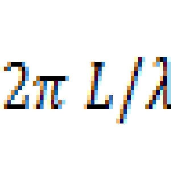

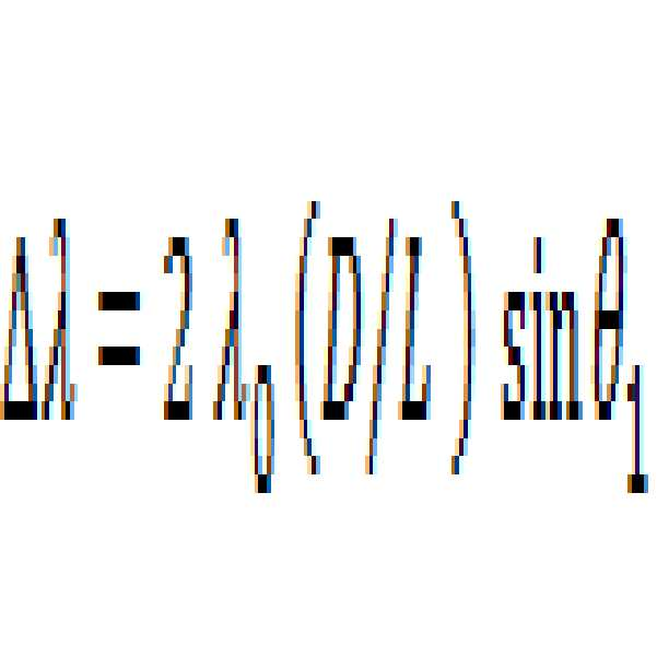



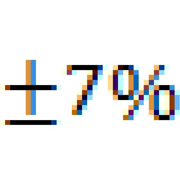


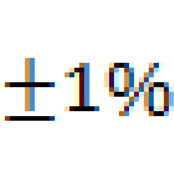

대안의 실시형태에서는, 


도 6의 위치 반사기는 정합 네트워크(620)를 통하여 안테나 포트(611)에 결합된 제1 포트를 갖는 지연 소자(625)를 포함한다. 지연 소자는 도 4의 지연 소자(425)와 동일하거나 유사할 수 있다(예컨대, BAW 또는 SAW 필터와 같은, RF 지연 수동 디바이스). 지연 소자(625)의 다른 포트는 접지에 단락된다. 여기에서, 반사기 상의 입사 방사는 반사기로부터의 재-방사 전에 지연 소자(625) 내에서 왕복 지연만큼 지연된다. 지연은 신호를 반사기로부터 되돌려 모바일로 반사하기 전에 부근 내 다른 기생 반사가 잦아들 수 있게 한다. 이것은 방 다중경로의 효과를 상당히 감축하고 모바일에서의 SNR을 개선할 수 있다. The position reflector of FIG. 6 includes a
일 실시형태에서, 지연 소자(625)의 지연은 어느 자유 대기 왕복 지연보다도 더 길고 그리고 인근 반사기는 다른 지연을 가져서, 예컨대, 레이더 신호를 인코딩하는데 선형 주파수 변조(LFM), 비-선형 FM, 또는 윈도잉된 (LFM)을 사용할 때 여러 다른 반사기로부터 유래하는 반사들 간을 모바일이 구별할 수 있게 한다. In one embodiment, the delay of
일 실시형태에서, 모바일로부터 방사된 신호는 직접 시퀀스 확산 스펙트럼(DSSS) 기술을 사용하여 변조된다. 이것은, 예컨대, 소정 칩 레이트에서, 참 난수 시퀀스(TRN), 또는 의사 난수(PRN) 시퀀스를 채용하는 BPSK 또는 QPSK 변조를 사용함으로써 행해진다. 소정 반사기에 대한 지연 소자(625)의 지연이 하나보다 많은 PRN 칩 주기만큼 다른 반사기와 다르면, 그때 모바일은 여러 다른 반사기로부터 유래하는 다수의 반사들 간을 구별할 수 있다. In one embodiment, the signal emitted from the mobile is modulated using Direct Sequence Spread Spectrum (DSSS) techniques. This is done, for example, by using a true random number sequence (TRN) or BPSK or QPSK modulation employing a pseudo-random number (PRN) sequence at a given chip rate. If the delay of the
일 실시형태에서, 정합 네트워크(620)는 지연 소자(625)와 안테나 구조 간 완벽한 정합을 제공하는 것으로부터 약간 디튜닝된다. 이것은 입사 신호의 일부분은 지연 소자(625)를 통해 하나의 왕복 지연 후에 되돌아 재방사되고 그리고 일부분은 되돌아 지연 소자(625) 내로 반사되는 결과를 초래한다. 이것은 입사 레이더 신호에 응답하여 반사기에 의해 다수의 반사가 재-방사되는 결과를 초래한다. 가장 강력한 반사는





도 7은 현재 개시된 실시형태에 따른 다른 위치 반사기의 기능적 블록 선도이다. 도 7의 위치 반사기는 도 6의 위치 반사기와 유사하며 유사한 요소는 유사한 기능을 수행한다. 도 7의 위치 반사기는 확산 렌즈(715)를 포함한다. 경로(703)를 따라 안테나 구조를 떠나는 방사는 확산 렌즈(715)를 통과하고 거기서 그것은 회절되고 경로(704)를 따라 계속 간다. 이것은 소정 주파수 스윕에 대해 안테나 스캔 각도를 증가시키는 효과를 가진다. 이러한 안테나 구조는 더 높은(예컨대, >10GHz) 주파수에서 특히 실용적일 수 있다. 이러한 렌즈는, 예컨대, 콜리메이팅 렌즈에 비해 역 지향성을 갖는다.7 is a functional block diagram of another position reflector according to the presently disclosed embodiment. The position reflector of FIG. 7 is similar to the position reflector of FIG. 6 and similar elements perform a similar function. The position reflector of FIG. 7 includes a diffusing
도 6 및 도 7에서의 안테나 구조는 하나의 방향으로의 스캐닝을 제공하고 그리하여 하나의 AOA를 제공할 수 있다. 단일 반사기 위치 결정에 2개의 AOA를 제공하기 위해서, 실내 위치결정 시스템은 2개의 직교 각도를 제공하도록 서로에 직교하여 장착 및 병설된 반사기 구조의 2개의 사본을 사용할 수 있다. 이들 반사기에 대한 많은 변형이 가능하고, 예컨대, 소자의 비-균일 어레이를 갖는 반사기이다. 다른 반사기 변형에서는 메타-재료에 기반하는 반사기 안테나를 사용한다. 이러한 반사기의 일례는 메타-재료 CRLH 누설 파 수동 재귀-지향성 반사기에 지연 소자를 부가한다(예컨대, "Electromagnetic Metamaterials: Transmission Line Theory and Microwave Applications", 2005년, Christophe Caloz 및 Tatsuo Itoh, 6.4.1절 참조). 여기에서 설명된 바와 같은 지연 소자는 안테나 단자와 단락 사이에 삽입되어 지연을 갖는 재귀-지향성 반사기를 생성하여 레이더 프로세싱을 단순화할 것이다. 그러한 반사기는 유익하게는 재귀-지향성, 수동이고, 하나의 누설 방사 소자를 가지고 그리하여 하나의 지연 소자만을 사용할 수 있다. CRLH(메타-재료)로 제작되는 것은 더 넓은 반사 각도(예컨대, 거의 180도)를 허용하는 것을 통해 표준 재료 누설 파 안테나 성능에 대해 개선할 수 있다. The antenna structures in Figures 6 and 7 provide for scanning in one direction and thus provide one AOA. To provide two AOAs for single reflector positioning, the indoor positioning system can use two copies of the reflector structure mounted and arranged orthogonally to each other to provide two orthogonal angles. Many modifications to these reflectors are possible, for example reflectors with a non-uniform array of elements. Other reflector variants use reflector antennas based on meta-materials. One example of such a reflector adds a delay element to the meta-material CRLH leakage wave passive recursive-directional reflector (see, for example, " Electromagnetic Metamaterials: Transmission Line Theory and Microwave Applications ", 2005, Christophe Caloz and Tatsuo Itoh, Reference). A delay element as described herein will be inserted between the antenna terminal and the short to create a recursive-directional reflector with delay to simplify radar processing. Such reflectors are advantageously recursive-directional, passive, and have only one leakage radiating element and thus can use only one delay element. Fabricating with CRLH (meta-material) can improve on standard material leakage wave antenna performance through allowing a wider reflection angle (e.g., about 180 degrees).
도 8은 현재 개시된 실시형태에 따른 다른 위치 반사기의 기능적 블록 선도이다. 도 8의 위치 반사기는 위상 공액 어레이(PCA) 반사기라고 지칭될 수 있다. 그러한 반사기는, 예컨대, 위치 반사기에서 전력 소스가 이용가능할 수 있는 상업용 설치에서 특히 적합할 수 있다. 큰 공간당 몇 반사기만이 사용되므로, 전력 소스의 수는 작다. Figure 8 is a functional block diagram of another position reflector according to the presently disclosed embodiment. The position reflector of Fig. 8 may be referred to as a phase conjugate array (PCA) reflector. Such a reflector may be particularly suitable, for example, in a commercial installation where a power source may be available in a position reflector. Since only a few reflectors are used per large space, the number of power sources is small.
도 8의 위치 반사기는 반사기 소자(815a-d)의 어레이를 포함한다. 각각의 반사기 소자는 안테나(810)를 포함한다. 안테나는 안테나 포트(811)에서 정합 네트워크(820)를 통하여 지연 소자(825)의 제1 포트에 결합된다. 지연 소자(825) 및 정합 네트워크(820)는 다른 반사기에 대해 설명된 바와 같이 구현될 수 있다. 마찬가지로, 정합 네트워크(820)는 이중 지연된 반사를 제공하도록 디튜닝될 수 있다. 지연 소자의 제2 포트는 반사기 혼합기(829)에 결합된다. 반사기 혼합기(829)는 국부 발진기(845)로부터의 신호와 혼합된 입사 신호인 신호를 반사한다. 도 8에서 예시된 바와 같이, 반사기 혼합기(829)는 서큘레이터 및 혼합기를 포함할 수 있다. 서큘레이터는 지연 소자(825)에 결합된 제1 단자, 제1 혼합기 입력에 결합된 제2 단자, 및 혼합기 출력에 결합된 제3 단자를 갖는다. 혼합기는 국부 발진기에 결합된 제2 입력을 가지고 그리고 제1 입력과 제2 입력 상의 신호를 혼합함으로써 혼합기 출력을 산출한다. 혼합기는 능동 또는 수동일 수 있다. The position reflector of Fig. 8 includes an array of
국부 발진기 주파수가 입사 파의 주파수의 2배이면, PCA는 입사 파를 재귀-지향성 되돌려 소스로 향하여 반사한다. 이러한 재귀-지향성은 여기 주파수가 국부 발진기 주파수의 절반으로부터 더 많이 이탈할수록 감축될 수 있다. 이러한 주파수 감도는 다른 중심 주파수를 갖는 가까운 옆 반사기들 간을 구별하는데는 물론 모바일이 소정 반사기의 재귀-지향성 중심 주파수 주위 송신 주파수를 디더링함으로써 반사기에서의 AOA를 구하는 방식을 제공하는데에도 사용될 수 있다. 부가적으로, PCA에 대한 이격은 중요하지 않고 그리하여 구조는 지지 벽, 천장 또는 바닥 가까이에 따를 수 있다. If the local oscillator frequency is twice the frequency of the incident wave, the PCA will return the incident wave back to the directional and reflect it towards the source. This recursive-directivity can be reduced as the excitation frequency deviates more than half of the local oscillator frequency. This frequency sensitivity can be used not only to distinguish between near side reflectors having different center frequencies but also to provide a way for the mobile to obtain the AOA at the reflector by dithering the transmit frequency around the recursive-directional center frequency of the given reflector. Additionally, the spacing for the PCA is not critical, and so the structure may follow the support wall, ceiling, or floor.
도 8의 반사기는 디지털 위상 시프터(840)를 포함한다. 위상 시프터(840)는 
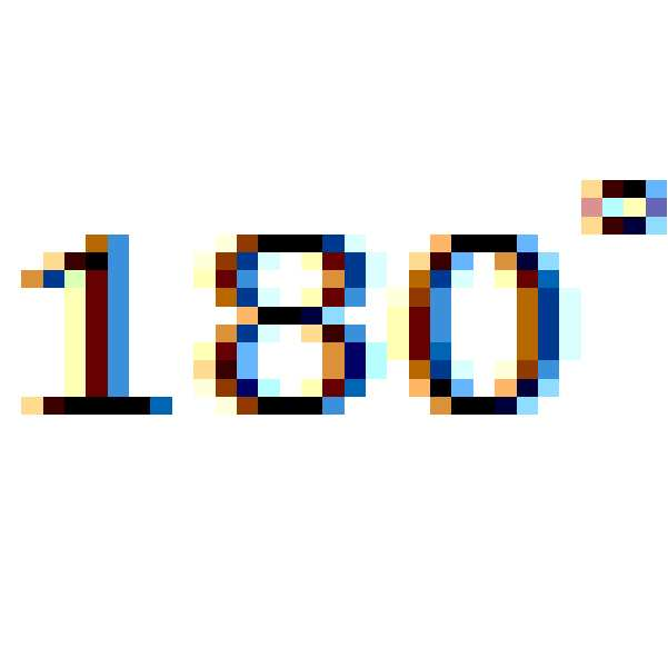
도 8의 반사기는 레인지 정보를 제공할 수 있지만 AOA 정보를 모바일에 제공하지는 않을 수 있다. 그렇지만, 그러한 반사기는 모바일 신호를 재귀-지향성 반사하고 그리하여 부근 내에서 동시에 서비스 제공받을 수 있는 모바일의 수를, 예컨대, RF 공간 다이버시티 및 더 낮은 필요한 SNR에 기인하여 증가시킨다. 이것은 많은 사용자를 갖는 대형 장소에, 예컨대, 몰, 스포츠 경기장 등에서 특히 중요하다. The reflector of FIG. 8 may provide range information but may not provide AOA information to the mobile. However, such a reflector increases the number of mobiles that can retroreflectively reflect the mobile signal and thus be served simultaneously in the vicinity, e.g., due to RF spatial diversity and lower required SNR. This is particularly important in large places with many users, such as in malls, sports arenas, and the like.
각각의 PCA-기반 반사기는 하나의 레인지 측정을 내놓는다. 모바일은 이들 PCA 기반 반사기 중 4개 이상으로부터 반사를 검출함으로써 그 위치를 정확하게 검출할 수 있다. 정확한 레인징을 위해, 여러 다른 반사기 소자(815)에서의 지연 소자(825)들은 타이트 정합되어야 한다. 반사기는 능동 디바이스이므로, 예컨대, SAW 또는 BAW 디바이스 대신에 디지털 지연 라인이 사용될 수 있다. 디지털 지연 라인은 신호를 더 낮은 주파수로 변환하기 위한 하향 변환기, 아날로그-대-디지털 변환기, 디지털 지연 시프트 레지스터, 그 다음에 디지털-대-아날로그 변환기, 및 신호를 그 원래 주파수로 복귀시키기 위한 상향 변환기를 포함할 수 있다. 이러한 방식으로 실현된 지연 소자는 완벽하게(또는 거의 그렇게) 정합된다. 대안으로, 경로는 하나의 경로로 결합되고 하나의 SAW 또는 BAW 지연 소자로 보내질 수 있다. 동일한 SAW 또는 BAW를 통과한 후에, 신호는 다시 그들 자신의 별개 경로로 분기된다. 신호는 주파수 분할 또는 코드 분할 RF 기술을 사용함으로써 동일한 지연 소자를 통과하는 동안 혼합되지 않게 유지될 수 있다. 그러한 접근법은 하나의 지연 소자만을 사용한다. 각각의 경로가 동일한 물리적 SAW 또는 BAW 소자에 의해 지연되기 때문에, 지연은 정합된다. Each PCA-based reflector provides one range measurement. The mobile can accurately detect its position by detecting reflections from four or more of these PCA based reflectors. For accurate ranging, the
도 8의 반사기의 변형에서, 신호 전부는 CDMA 기술을 사용하여 하나의 지연 소자를 통해 멀티플렉싱된다. 각각의 정합 회로(820)로부터의 신호는 서큘레이터를 통과해 Tx 경로와는 별개의 Rx 경로로 간다. 각각의 안테나의 Rx 경로는 그 후 각각의 경로에 고유한 PN 시퀀스와 혼합된다. PN 혼합 후에, 경로 전부는 결합되고 동일한 지연 소자를 통과한다. 지연 소자를 빠져나가, 결합된 신호는 안테나당 하나의 경로로 분기된다. 그 후, 각각의 경로는 결합 전에 사용된 그 대응하는 PN 시퀀스와 다시 혼합되지만 공통 지연 소자의 기지의 지연만큼 지연된다. 신호는 혼합 고조파를 제거하도록 대역-통과 필터를 통과한다. 그 후, 각각의 경로는 그들 위상 공액 신호를 발생시키도록 (레이더 신호의 중심 주파수의 2배인) 국부 발진기(포함될 때 위상 시프트 후) 주파수와 혼합된다. 이러한 혼합 후에, 신호는 고조파 및 높은 주파수 적 성분을 제거하도록 필터링되고 그 후 경로 서큘레이터의 Tx측으로 전달된다. 위의 것을 행함에 있어서, 각각의 수신 신호는 공액화되고 모든 다른 경로와 동일한 지연만큼 지연되는데 모든 경로가 동일한 지연 소자를 사용하기 때문이다. 완전 구조는 그때 내장 지연을 갖는 재귀-지향성 반사기이다. In a modification of the reflector of Figure 8, all of the signal is multiplexed through one delay element using CDMA techniques. The signal from each matching
다른 실시형태에서, 반사기는 위에서 예시 및 설명된 유형의 4개 이상의 반사기를 포함하는 복합 반사기이며, 여기서 각각은 재귀-지향성이고 그리고 각각으로부터의 반사는 복합 반사기 내 다른 것들과 구별가능하다. 반사기는 방위 및 고도 각도 결정을 제공하기 위해 단일 선형 라인을 따라 있지 않도록 배열된다. 복합 반사기 내 반사기의 각각 간 위상차는 RAKE 수신기에 의해 구별되고 그리하여 복합 반사기에서의 2개의 AOA가 결정될 수 있다.In another embodiment, the reflector is a composite reflector comprising four or more reflectors of the type illustrated and described above, wherein each is recursive-directional and the reflections from each are distinguishable from others in the composite reflector. The reflectors are arranged so as not to follow a single linear line to provide azimuth and elevation angle determination. The phase difference between each of the reflectors in the composite reflector is differentiated by the RAKE receiver so that two AOAs in the composite reflector can be determined.
복합 반사기 내 이웃 반사기들 간 거리가 하나보다 많은 파장이고 그리하여 정수 파장 모호성은 올바른 AOA 결정을 위해 분해되어야 하므로 3개보다 많은 반사기가 사용된다. 모호성을 분해하기에 충분한 정보를 발생시키기 위해 부가적 반사기는 등거리에 배치되어서는 안된다. 복합 반사기 내 반사기들 간 정수 모호성을 분해하도록 중심 주파수 디튜닝, 반사된 전력, 및 주파수 디더링이 또한 사용될 수 있다. More than three reflectors are used because the distance between neighboring reflectors in the composite reflector is more than one wavelength and integer wavelength ambiguity must be decomposed for correct AOA determination. The additional reflectors should not be equidistant to generate sufficient information to resolve the ambiguity. Center frequency detuning, reflected power, and frequency dithering may also be used to resolve the integer ambiguity between the reflectors in the composite reflector.
도 9는 현재 개시된 실시형태에 따른 위치 반사기의 등측도이다. 도 9의 위치 반사기는, 예컨대, 도 6, 도 7 및 도 8의 반사기를 구현하는데 사용될 수 있다. 반사기는 상부층 및 하부층에 부가하여 다수의 전도 구리층을 갖는 인쇄 회로 기판(911)을 포함한다. 상부층(912)은 여러 방사 소자(안테나)(910)를 포함하고 있도록 패터닝된다. 이들 방사 소자는, 예컨대, 소망의 방사 패턴에 기반하여 어느 기하학적 형상이라도 될 수 있다. 방사 소자는 단지 명확한 예를 제공하기 위해 직사각형으로 예시된다. 상부층과 하부층 사이에 있는 층은 분기 급전 네트워크를 구축하는데 사용될 수 있다. 하부층은 수동 또는 능동 회로를 장착하도록 트레이스를 가질 수 있다. 방사 소자가 수평으로 반복되므로, 최대 방사의 방향은 평면(902)과 일치하는 벡터(903)와 정렬된다. 이러한 가상 평면은 방사 소자(910)의 수평 분포에 기인하여 수평선과 반사기를 교차시킨다. 그렇지만, 방사 소자(910)의 형상에 종속하여, 평면(902)은 반사기의 평면에 법선일 필요는 없다. 또한, 방사 소자는 똑같을 필요는 없다. 또한, 방사 소자들 간 페이징은 주파수와 최대 방사 방향의 비대칭 스캐닝을 초래하는 방식으로 행해질 수 있음을 주목한다. 예컨대, 벡터(903)는 좌측보다 우측으로 더 스캐닝할 수 있다. 9 is an isometric view of a position reflector according to the presently disclosed embodiment. The position reflector of Fig. 9 can be used, for example, to implement the reflector of Figs. 6, 7 and 8. The reflector includes a printed
도 10은 현재 개시된 실시형태에 따른 위치 반사기의 평면도이다. 도 10의 반사기는 섹터링된 반사기라고 지칭될 수 있다. 섹터링된 반사기에 대해, 각각 다른 페이징 바이어스를 갖는, 도 9의 다수의 선형 반사기는 서로 옆에 적층되어 평탄한 섹터링된 반사기를 초래한다. 10 is a plan view of a position reflector according to the presently disclosed embodiment. The reflector of FIG. 10 may be referred to as a sectored reflector. For the sectored reflectors, the multiple linear reflectors of FIG. 9, each having a different paging bias, are stacked next to each other resulting in a flat sectored reflector.
도 11은 현재 개시된 실시형태에 따른 다른 위치 반사기의 평면도이다. 도 11의 반사기는 2개의 AOA를 내놓을 수 있다. 반사기는 2개의 인접 반사기를 포함한다. 각각은, 예컨대, 도 9에 도시된 바와 같은 단일 선형 반사기 또는 도 10에 도시된 바와 같은 섹터링된 반사기일 수 있다. 제1 반사기(1120)는 수평 방사 평면으로 정향되고, 그리고 제2 반사기(1121)는 방사 평면이 수직이게 되도록 제1 반사기(1120)에 비해 회전되어 있다. 11 is a plan view of another position reflector according to the presently disclosed embodiment. The reflector of Fig. 11 can provide two AOAs. The reflector includes two adjacent reflectors. Each may be, for example, a single linear reflector as shown in Fig. 9 or a sectored reflector as shown in Fig. The
도 12는 현재 개시된 실시형태에 따른 송신 및 수신 레이더 체인의 기능적 블록 선도이다. 송신 체인(1205) 및 수신 체인(1255)은, 예컨대, 상보적 금속 산화물 반도체(CMOS) 시스템-온-어-칩 집적 회로를 사용하여 모바일 디바이스에 구현될 수 있다. 예시된 송신 및 수신 체인은 예시이고 그리고 다른 적합한 배열이 또한 사용될 수 있다. 12 is a functional block diagram of transmit and receive radar chains according to the presently disclosed embodiment. The transmit
송신 체인(1205)은 I 및 Q 변조기를 포함한다. 송신 체인(1205)에 대해, 동상(TX_I) 및 직교-위상(TX_Q) 값에 대한 디지털 데이터 샘플은, 예컨대, 디지털 신호 프로세서(DSP)로부터 공급된다. I 및 Q 샘플 스트림은 DC 중심, 또는 낮은 IF 중심 샘플링된 데이터를 반송하고 있을 수 있다. 데이터는, 안티-에일리어싱 필터를 또한 포함하고 있을 수 있는, 디지털-대-아날로그 변환기(DAC)(1231, 1232)를 사용하여 아날로그 레벨로 변환된다. DAC의 샘플링 클록은 코히어런스를 유지하고 있도록 국부 발진기(LO)와 동기화될 수 있다. 샘플 클록은 에일리어싱을 회피하도록 적어도 송신 신호의 대역폭의 2배이다. 위상 고정 루프(PLL)(1225)를 포함하고 있는 국부 발진기(LO)는 주파수 참조(1240)에 위상 고정되고 그리고 I 및 Q RF 혼합기(1221, 1222)를 사용하여 기저 대역 I 및 Q 신호를 반송파 주파수로 상향 변환하도록 IQ 신호를 발생시킨다. 상향 변환된 I 및 Q 신호는 합산 네트워크(1215)에서 합산 및 필터링된다. 그 후, 결합된 신호는, 기저대역 또는 애플리케이션 프로세서에 있을 수 있는, 전력 제어 알고리즘에 의해 제어되는 바와 같이 송신 출력 전력을 조절하도록 가변 이득 증폭기(1213)를 통과한다. 그 후, 신호는 스퓨리어스 대역 외 방출을 제거하도록 대역 선택 필터(1211)를 통과하고 그 후 송신 안테나(1210)에 전달된다. The transmit
수신 체인(1255)에 대해, 수신된 신호는 대역-외 신호를 거절하고 전반적 신호-대-잡음 비(SNR)를 개선하도록 대역 선택성 필터(1261)에 수신 안테나(1260)로부터 우선 라우팅된다. 그 후, 신호는 가변 이득 및 가변 IP3 저잡음 증폭기(LNA)(1263)에 공급된다. LNA(1263)로부터 나와, 신호는 전력 분배기(1265)를 사용하여 분기된다. 분기 신호는 RF 혼합기(1271, 1272)를 사용하여 기저 대역 또는 낮은 IF I 및 Q 신호 스트림으로 하향 변환된다. 그 후 신호는 결합된 필터 및 아날로그-대-디지털 변환기 블록(ADC)(1281, 1282)에 의해 필터링 및 샘플링된다. 수신 PLL LO 발생기(1275)로부터의 수신 LO 및 ADC 클록은 양자가 주파수 참조(1240)와 그리하여 송신 체인과 동기화되고 그로써 코히어런스를 유지하고 있다. ADC로부터의 디지털 샘플은 동상 샘플(RX_I) 및 직교 샘플(RX_Q)로서 수신 체인을 빠져나간다. I 및 Q 수신 디지털 데이터 스트림은 추가적 프로세싱을 위해 모바일에서의 수신 DSP에 보내진다. For the receive
도 12의 송신 및 수신 체인은 별개의 안테나를 사용한다. 이러한 실시형태는 하프 듀플렉스에 사용될 수 있고 그리고 풀 듀플렉스 동작 동안 소정 TX-RX 격리를 제공할 수 있다. The transmit and receive chains of Figure 12 use separate antennas. This embodiment can be used for half duplex and can provide some TX-RX isolation during full duplex operation.
도 13은 현재 개시된 실시형태에 따른 대안의 안테나 배열을 갖는 추가적 송신 및 수신 레이더 체인의 기능적 블록 선도이다. 도 13에 예시된 실시형태는 도 12의 그것과 유사하지만 송신 체인과 수신 체인이 안테나를 공유한다. 송신 체인(1307) 및 수신 체인(1355)은 송신/수신(T/R) 스위치(1307)를 통해 하나의 안테나(1310)에 접속된다. T/R 스위치(1307)는 안테나를 송신 체인(1305) 또는 수신 체인(1355) 중 어느 하나에 교번 접속시킨다. 이것은 레이더 신호의 송신 및 수신이 하프 듀플렉스에서 행해지는 경우에 사용된다. 하프 듀플렉스 동작에서, 모바일은 단시간 동안 레이더 신호를 송신하고 그 후 송신기를 오프로 하고 반사를 경청한다. 이러한 배열의 이점은 모바일이 반사를 경청하고 있을 때 송신 레이더 신호가 오프로 되어 있고 그리하여 Tx/Rx 누설에 면역성이 있다는 것이다. 그렇지만, 하프 듀플렉스는 다수의 구별되는 지연을 갖는 다수의 반사기가 존재할 때 Rx/Tx 스케줄링을 복잡하게 만들 수 있다.13 is a functional block diagram of an additional transmitting and receiving radar chain with an alternative antenna arrangement according to the presently disclosed embodiment. The embodiment illustrated in FIG. 13 is similar to that of FIG. 12, but the transmit chain and the receive chain share an antenna. The transmit
도 14는 현재 개시된 실시형태에 따른 다른 대안의 안테나 배열을 갖는 추가적 송신 및 수신 레이더 체인의 기능적 블록 선도이다. 도 14의 실시형태는 도 13의 그것과 유사하지만 대안의 안테나 접속을 사용한다. 도 14에서, 송신 체인 및 수신 체인 양자는 풀 듀플렉스 동작으로 동시에 동작하고 있을 수 있다. 신호는 서큘레이터(1408)를 통해 안테나(1410)에 라우팅된다. 서큘레이터(1408)는, 예컨대, 약 20dB Rx-Tx 격리를 제공할 수 있다. Tx 신호의 감쇠된 사본을 측정하고 그리고 그것을 에코 소거 디지털 신호 프로세싱을 사용하여 Rx 신호로부터 소거함으로써 부가적 격리가 행해질 수 있다. 마지막으로, 부가적 격리는 반사기의 하나보다 더 긴 칩 주기 내장 지연에 기인하여 Tx와 Rx DSSS 신호 간 하나보다 많은 칩 지연 오프셋에 의해 제공될 수 있다. 14 is a functional block diagram of an additional transmitting and receiving radar chain with another alternative antenna arrangement according to the presently disclosed embodiment. The embodiment of Fig. 14 is similar to that of Fig. 13, but uses an alternative antenna connection. In Fig. 14, both the transmit chain and the receive chain may be operating simultaneously in a full duplex operation. The signal is routed to the
도 14의 배열을 사용하는 모바일에서는, Tx와 Rx 양자가 동시에 동작할 수 있더라도, Tx 신호는, 예컨대, Tx 이득 스테이지 및 전력 증폭기를 오프로 함으로써 주기적으로 침묵할 수 있다. 예컨대, 위치 반사기가 약 3 마이크로초를 클러스터링하는 지연을 가지면, Tx 신호는 3 마이크로초 동안 송신되고 6 마이크로초 동안 오프로 된다. 송신하는 동안, 수신기는 오프로 되어 있다. Tx가 오프로 될 때, Rx 섹션은 데이터를 수신 및 프로세싱한다. 6 마이크로초는 DDR의 일차 및 이차 반사를 수신하는데 사용된다. DSSS 신호를 사용하여, 이것은 -4.8 dB 손실을 초래할 수 있지만 설계를 대단히 단순화할 수 있는데, 예컨대, 그것이 자가-재밍을 제거하기 때문이다. In the mobile using the arrangement of Figure 14, even though both Tx and Rx can operate simultaneously, the Tx signal can be periodically silenced, for example, by turning off the Tx gain stage and the power amplifier. For example, if the position reflector has a delay clustering about 3 microseconds, the Tx signal is transmitted for 3 microseconds and turned off for 6 microseconds. During transmission, the receiver is off. When Tx is off, the Rx section receives and processes the data. Six microseconds are used to receive the primary and secondary reflections of the DDR. Using the DSSS signal, this can lead to -4.8 dB loss, but the design can be greatly simplified, for example, because it eliminates self-jamming.
도 15는 현재 개시된 실시형태에 따른 측위 신호 프로세싱의 기능적 블록 선도이다. 측위 신호 프로세싱은 위치 측위를 위해 모바일에 의해 수행될 수 있다. 송신 디지털 신호 프로세서(1507)는 동상(TX_I) 및 직교-위상(TX_Q) 값을 공급한다. 그 값은, 예컨대, 도 12의 송신 체인(1205)에 공급될 수 있다. 수신 디지털 신호 프로세서(1557)는 동상(RX_I) 및 직교-위상(RX_Q) 값을 수신한다. 그 값은, 예컨대, 도 12의 수신 체인(1255)으로부터 수신될 수 있다. 송신 디지털 신호 프로세서(1507) 및 수신 디지털 신호 프로세서(1557)는 물리적으로 겹치지 않을 수 있거나 또는 송신 및 수신 프로세싱 알고리즘 양자를 병행 실행하는 동일한 프로세서일 수 있다. 송신 디지털 신호 프로세서(1507) 및 수신 디지털 신호 프로세서(1557)는 애플리케이션 프로세서(1559)에 의해 관리될 수 있다. 송신 및 수신 데이터 스트림을 프로세싱하는 것에 부가하여, 다양한 조합에서, 송신 디지털 신호 프로세서(1507), 수신 디지털 신호 프로세서(1557), 및 애플리케이션 프로세서(1559)는, 여러 다른 RF 체인 북 키핑 동작 중에서도, LO 주파수 선택, Tx 출력 전력 제어, Rx 입력 저잡음 증폭기(LNA) 이득 및 IP3 제어, T/R 스위치 제어, 및 송신/수신 스케줄링과 같은, 송신 및 수신 체인의 다른 태양을 제어한다. 프로세싱을 위한 프로그래밍가능한 블록을 사용하는 것은 소정 송신 파형에 대한 AOA 및 레인지를 검출하도록 수신 체인에서의 적합한 가역 프로세싱과 함께 송신 레이더 신호에 대한 적합한 변조 방법, 대역폭, 및 중심 주파수를 선택하는데 상당히 큰 융통성을 모바일에 준다. 15 is a functional block diagram of positioning signal processing according to the presently disclosed embodiment. Positioning signal processing may be performed by the mobile for position location. The transmit
도 16은 현재 개시된 실시형태에 따른 송신 측위 신호 프로세싱의 기능적 블록 선도이다. 도 16의 블록은, 예컨대, 도 15의 송신 디지털 신호 프로세서(1507)에서 사용될 수 있다. 도 16의 송신 측위 신호 프로세싱은 {+1,-1} 샘플의 의사-랜덤 시퀀스를 발생시키는 송신 의사-잡음 발생기(1609)를 포함한다. 송신 의사-잡음 발생기(1609)는 선형 피드백 시프트 레지스터(LFSR)를 사용하여 최대 다항식에 의해 시퀀스를 발생시킬 수 있다. 송신 로테이터(1604)는 송신 I 및 Q 샘플을 회전시킬 수 있다. 일 실시형태는 I 채널 상에 BPSK 변조가 있고 Q 채널 상에 아무것도 없는 샘플을 사용할 수 있다. 이들 I 및 Q 샘플은 Tx 체인의 다음 스테이지에 전달되기 전에 송신 로테이터(1604)에서 회전된다. 송신 로테이터(1604)는 송신 신호의 중심 주파수를 시프트하는데 사용된다. 로테이터는 송신 램프 발생기(1608)에 의해 구동된 직접 디지털 합성기(DDS)(1606)로부터 샘플당 회전의 각도 증분을 수신한다. 송신 램프 발생기(1608)는 영 주파수 오프셋으로부터 시작하여 기저 대역에서의 샘플링 주파수의 절반과 같은 오프셋까지 프로그래밍가능할 수 있다. 시스템의 주 프로세서는 송신 램프 발생기(1608)를 사용하고 또한 엔드 주파수 시프트 및 주파수 시프트의 속도(Hz/초)로 로딩하도록 적합한 다항식으로 송신 의사-잡음 발생기(1609)를 프로그래밍할 수 있다. 그 후, 주 프로세서는 시작 커맨드를 발행할 수 있고 이 경우 송신 의사-잡음 발생기(1609) 및 송신 램프 발생기(1608)는 동기식으로 동작을 개시한다. 그리하여, 각각의 순시 시프트 주파수는 PN 코드의 PN 위상에 타이트 정렬된다. 16 is a functional block diagram of the transmitted positioning signal processing according to the presently disclosed embodiment. The block of FIG. 16 may be used, for example, in the transmit
송신 측위 신호 프로세싱은 또한 Rx 신호 체인측에서 사용될 수신 의사-잡음 발생기(1659), 수신 램프 발생기(1558), 및 수신 DSS(1656)를 포함한다. 수신 의사-잡음 발생기(1659)는 송신 의사-잡음 발생기(1609)와 동일한 다항식으로 로딩되고, 그리고 수신 의사-잡음 발생기(1659)는 송신 의사-잡음 발생기(1609)와 동일한 순간에 시작된다. 그렇지만, 수신 의사-잡음 발생기(1659)는 발생된 Rx PN 시퀀스가 결정된 수의 샘플만큼 Tx PN 시퀀스 뒤에 처지는 결과를 초래하는 다른 초기 조건으로 로딩된다. 유사하게, 수신 램프 발생기(1558)는 송신 램프 발생기(1608)와 동일한 목표 주파수 시프트 및 동일한 시프트 레이트로 프로그래밍되고 그리고 또한 송신 램프 발생기(1608)와 동기식으로 시작된다. 그렇지만, 수신 램프 발생기(1558)는 Rx측 상의 램프가 Tx 램프 뒤에 처지게 하는 다른 초기 조건으로 프로그래밍된다. 수신 램프 발생기(1558)는 수신 회전 계수를 발생시키도록 수신 DSS(1656)를 구동한다. Rx PN 시퀀스 및 수신 디지털 신호 프로세서(1557)의 출력 양자는 Rx 샘플을 프로세싱하는데 사용된다. Tx 샘플에 비해 Rx PN과 램프 샘플 간 지연에 대한 이유는 반사 레이더 신호의 왕복 지연을 감안하는 것이다. 일 구현에서, 발생기는 10의 초당 백만 칩(10MCPS)의 레이트로 실행된다. 모바일이 외부 신호 개조 없이 신호를 발생도 그리고 검출도 하고 그리하여 현재 조건에 기반하여 필요한 무엇이라도 그것이 Tx로부터 Rx까지 자기-모순이 없는 한 사용할 수 있으므로, 모바일은 이러한 레이트를 마음대로 변화시킬 수 있음을 주목하는 것이 중요하다. Transmit positioning signal processing also includes a receive
도 17은 현재 개시된 실시형태에 따른 수신 측위 신호 프로세싱의 기능적 블록 선도이다. 도 17의 블록은, 예컨대, 도 15의 수신 디지털 신호 프로세서(1557)에서 사용될 수 있다. 수신 측위 신호 프로세싱은 샘플 로테이터(1754), I 및 Q 상관기(1765)의 뱅크, 및 FIFO(1767)를 포함한다. Rx RF 샘플은 대응하는 송신 신호를 발생시키는데 사용된 값에 따라 샘플 로테이터(1754)에 의해 우선 회전된다. 예컨대, 도 16의 송신 측위 신호 프로세싱과 사용될 때, 샘플 로테이터(1754)는 수신 DSS(1656)로부터 회전 값을 수신할 수 있다. 17 is a functional block diagram of received positioning signal processing according to the presently disclosed embodiment. The block of FIG. 17 may be used, for example, in the received
그 후, 회전된 샘플은 Rx PN 시퀀스와 상관하도록 상관기(1765)에 공급된다. 상관기 및 그들 대응하는 로테이터는 다수의 반사기 에코를 찾도록 송신 디지털 신호 프로세서에서 발생된 정보를 사용할 수 있다. 도 16의 송신 측위 신호 프로세싱과 사용될 때, Rx PN 시퀀스는 수신 의사-잡음 발생기(1659)에 의해 공급될 수 있다. 일례의 구현에서는, 32 I 및 32 Q 상관기들이 있다. 상관기 쌍의 각각은 들어오는 Rx 샘플을 Rx PN 시퀀스의 시프트된 사본과 상관시킨다. 각각의 PN 시퀀스 사이클에서, 상관기의 적분 결과는, 예컨대, 직접 메모리 액세스(DMA) 메커니즘을 사용하여 FIFO(1767)를 통해 주 프로세서에 덤프된다. 상관기 합에서의 큰 값은 그 상관기에 의해 사용된 PN 오프셋에서의 반사기 신호를 표시하고 레인지 측정에 대응한다. 또한, 동일한 PN 및 로테이터 값을 사용하는 I와 Q 경로 상관기들 간 상대 크기는 Q/I의 아크탄젠트를 컴퓨팅함으로써 이러한 에코의 반송파 위상을 내놓는다. 더 미세한 시간 분해능을 얻기 위해, Rx 샘플의 샘플 레이트는 PN 칩핑 레이트의 배수로 유지될 수 있다. 일 실시형태에서는, Tx PN 칩핑 레이트보다 8배 더 높은 Rx 샘플 레이트가 사용된다. 10MCPS PN 레이트를 사용하는 일례의 구현에 대해, Rx RF 신호는 80MSPS에서 샘플링 및 프로세싱된다. The rotated sample is then supplied to
주기적으로, 주 프로세서는 상관기(1765)의 결과를 얻는다. 프로세서는 이들 상관기 합 중 피크(최대)를 찾는다. 
소정 식별된 에코에 대해, 다음의 프로세싱이 수행될 수 있다. 송신 레이더 신호가 중심 주파수 




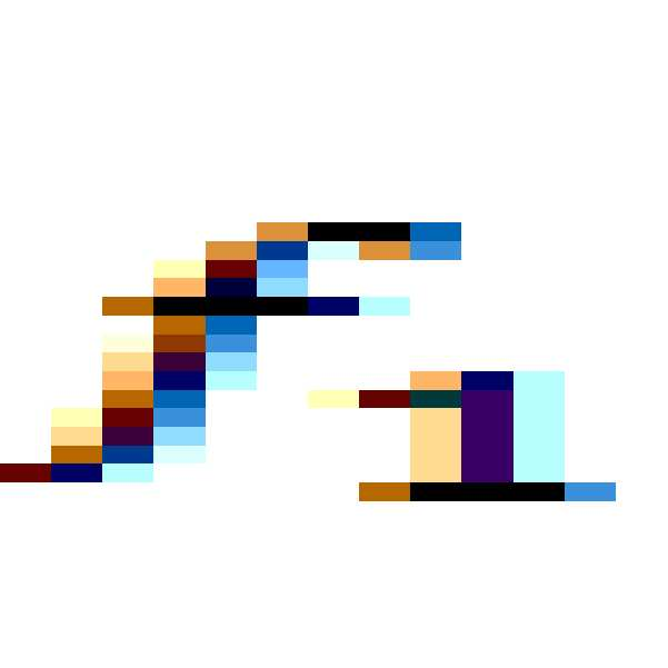










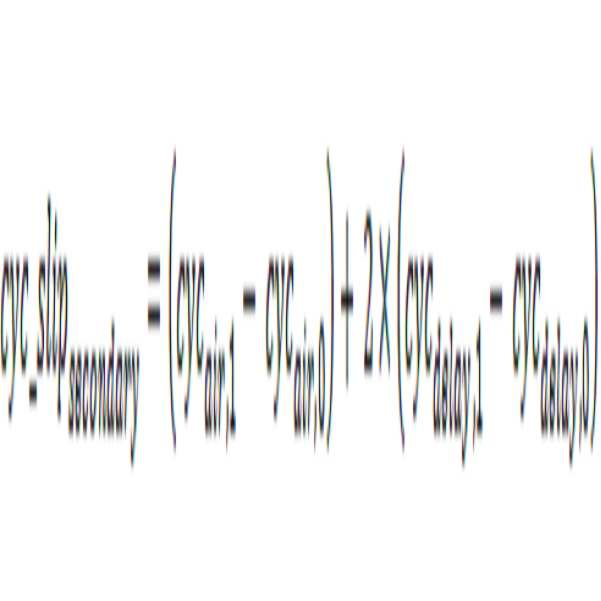
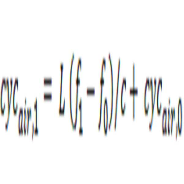

위의 식으로부터, 위치결정 프로세스는 
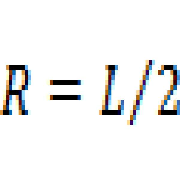
위 방법은 그것이 지연 소자 제조 및 환경 변형에 대한 레인지 측정의 어느 종속성이라도 제거하고 끊임없는 반사기 교정에 대한 필요성을 제거하므로 유용하다. 또한, 에코의 지연 소자 지연을 반송파 위상 레벨에서의 정확도로까지 결정하는 것은 검출된 반사 신호가 유래하는 대응하는 반사기를 식별하는데 도움을 준다. 2.4 GHz에서 동작하는 시스템에 대해, 각각의 반송파 사이클은 12cm에 걸쳐 이어진다. 이용가능한 SNR에 종속하여, 나노초 레벨에서의 그들 상이한 지연 소자 지연을 통해 구별되는 반사기를 식별하는 것은 물론 센티미터 레벨 레인지 정확도를 획득하는 것도 가능하게 된다. 이것은 동일한 부근 내 수백의 구별되는 반사기들 간 구별이 가능하다. The above method is useful because it removes any dependence of the range measurement on the delay element fabrication and environmental strain and eliminates the need for constant reflector calibration. Also, determining the delay element delay of the echo to the accuracy at the carrier phase level helps to identify the corresponding reflector from which the detected reflected signal originates. For a system operating at 2.4 GHz, each carrier cycle spans 12 cm. Depending on the available SNR, it is also possible to obtain centimeter level range accuracy as well as to identify reflectors that are distinguished through their different delay element delays at the nanosecond level. This makes it possible to distinguish between hundreds of distinct reflectors in the same vicinity.
위의 것은 좁은 주파수 시프트가 반사기의 레인지 및 지연을 어떻게 측정할 수 있는지 개괄한다. 이러한 좁은 주파수 스윕을 수행하기 이전에, 넓은 주파수 스윕이 행해질 수 있다. 이러한 넓은 주파수 스윕은 주파수 스캐닝된 유형 반사기에 대해 최적 주파수를 검출하도록 설계된다. 최대 반사 주파수가 검출되고 나면, 그 지점 주위의 좁은 주파수 스윕은 레인지 및 지연을 측정하도록 수행된다. 이것은 띄엄띄엄한 수의 반사기를 갖는 장소에서만 행해질 수 있고 그리하여 AOA를 내놓는 주파수 스윕된 반사기의 사용은 가치 있게 된다. 3개보다 많은 반사기가 검출가능한 환경에서, AOA는 무시되어 넓은 주파수 스윕을 필요로 하지 않을 수 있다. The above outlines how a narrow frequency shift can measure the range and delay of the reflector. Prior to performing such a narrow frequency sweep, a wide frequency sweep may be performed. This wide frequency sweep is designed to detect the optimal frequency for a frequency scanned type reflector. Once the maximum reflected frequency is detected, a narrow frequency sweep around that point is performed to measure the range and delay. This can only be done in places with a sparse number of reflectors, so the use of a frequency swept reflector that emits an AOA is worthwhile. In an environment where more than three reflectors can be detected, the AOA may be ignored and may not require a wide frequency sweep.
다중 사용자 환경을 지원하고 혼란스러운 반사를 감축하기 위해, 능동 전력 제어가 구현될 수 있다. 능동 전력 제어는 출력 Tx 전력을 조절하도록 수신 반사 측정 전력을 연속적으로 사용한다. 이것은 최소 RF 전력이 그 위치를 결정하도록 하나의 모바일에 의해 송신되는 결과를 초래한다. 부가적으로, 각각의 모바일에 대해 다른 또는 시간 시프트된 LFSR 다항식은 각각의 모바일이 그 자신의 발생된 레이더 신호에 의해 야기된 반사만을 검출함을 보증한다. To support a multi-user environment and to reduce confusing reflections, active power control can be implemented. Active power control consecutively uses the received reflected power to regulate the output Tx power. This results in the minimum RF power being transmitted by one mobile to determine its location. Additionally, different or time shifted LFSR polynomials for each mobile ensure that each mobile detects only the reflections caused by its own generated radar signal.
여기에서의 대부분의 설명은 모바일이 정지되어 있고(또는 거의 그렇고) 그리하여 도플러에 기인하는 Tx 대 Rx 주파수 시프트의 효과가 무시될 수 있다고 가정하였다. 이것은 위치 고정이 일 밀리초보다 적게 걸릴 수 있으므로 대다수의 실내 상황에 대해 참이다. 비현실적인 30 km/시 실내 속도에서라도, 2.4 GHz에서의 도플러는 밀리초당 25도보다 더 작다. 그렇지만, 위치결정 시스템은 소정 기간 동안 반송파 주파수를 고정(스윕하지 않음)하면서 사이클 슬립 레이트로부터 그것을 측정함으로써 도플러의 효과를 보정할 수 있다. Most of the explanations here assume that the mobile is stationary (or nearly so) and thus the effect of Tx versus Rx frequency shift due to Doppler can be ignored. This is true for the majority of indoor situations because the position fix can take less than one millisecond. Even at an unrealistic 30 km / h indoor speed, the Doppler at 2.4 GHz is less than 25 degrees per millisecond. However, the positioning system can compensate for the effect of Doppler by measuring it from the cycle slip rate while fixing (not sweeping) the carrier frequency over a period of time.
설치 프로세스의 개관이 이제 제공될 것이다. 설치 동안, (예컨대, 도 1의 서버(194)에서) 반사기 데이터가 업로드된다. 반사기 데이터는, 예컨대, 서버 데이터베이스에 추가 또는 변경하도록 특권을 부여받은 설치자에 의해 인터넷을 통해 업로드될 수 있다. 반사기 데이터는 여러 인터넷 접속된 컴퓨팅 디바이스 중 어느 것이라도 사용하여, 예컨대, 브라우저를 사용하여 업로드될 수 있다. 소정 구역에서 위치 반사기를 부착한 후에, 서버에 업로드될 반사기 데이터는 다양한 방식으로 획득될 수 있다. 정보는, 예컨대, 상업용 환경에서, 반사기마다 위치 및 정향을 결정하도록 정확한 건물 청사진 및 측량 장비로부터 획득될 수 있다. 또한, 소정 반사기에 특정적인 정보는 제조자 데이터 시트로부터 다운로드될 수 있다. 모든 이러한 정보는 수집되어 설치자에 의해 서버에 업로드될 수 있다. An overview of the installation process will now be provided. During installation, reflector data is uploaded (e.g., at
대안으로 또는 부가적으로, 위치결정 능력을 갖는 모바일은 국부 좌표계에 관해 여러 이전에 측량된 지점에 위치하는 동안 위치 결정을 하도록 사용될 수 있다. 충분한 데이터 지점이 취해지면, 서버는 그들 측정된 대응하는 소자 지연과 함께 그것이 에코를 수신하는 각각의 반사기의 위치를 결정할 수 있다. 4개의 비-평면 지점만으로 기하학적으로는 모든 검출가능한 반사기에 충분하다. Alternatively or additionally, a mobile with positioning capability can be used to make positioning while located at several previously measured points with respect to the local coordinate system. Once sufficient data points have been taken, the server can determine the location of each reflector for which it receives echoes along with their corresponding corresponding element delays. Only four non-planar points are sufficient for all detectable reflectors geometrically.
반사기 및 모바일 위치의 기하구조를 방에 있는 물리적 벽 및 물체에 관련시키기 위해 다음의 방법론이 사용될 수 있다. 소프트웨어 패키지는 방의 여러 사진으로부터 방 내 물체를 포함하여 방의 3D 모델을 생성할 수 있다. 반사기를 측위하기 위한 측정 지점이 사진 중 일부 내에서 식별되면, 그때 방의 3D 맵은 반사기의 좌표계에 대한 고정된 관계를 갖고 그리하여 모바일의 이동은 방의 3D 모델 내에서 3D로 플롯팅될 수 있다. 이것은 애플리케이션 개발자가 여기에서 개시된 위치 시스템 및 방법에 따라 발생된 데이터를 사용하는데 큰 도움을 제공할 수 있다. The following methodology can be used to relate the geometry of the reflector and mobile location to the physical walls and objects in the room. A software package can create a 3D model of a room, including objects in the room, from multiple pictures of the room. If a measurement point for positioning the reflector is identified within a portion of the photograph, then the 3D map of the room has a fixed relationship to the reflector's coordinate system so that the movement of the mobile can be plotted in 3D in the 3D model of the room. This can be a great help for application developers to use data generated according to the location systems and methods disclosed herein.
조합 설치 프로세스는 다음과 같이 동작한다. 반사기를 설치한 후에, 디지털 카메라를 위치결정 및 구비한 모바일은 방의 내부의 여러 사진을 찍게 된다. 사진이 스냅핑될 때마다, 모바일은 그것이 검출하는 모든 반사기에 대해 레인지 및 반사기 지연을 측정한다. 몇 지점 후에, 모바일은 모바일 및 서로에 상대적으로 반사기 위치를 측위할 수 있다. 이러한 정보는 방의 3D 모델이 구축되는 한편 동시에 설치된 반사기의 모델 좌표계 위에 놓이는 찍힌 사진에 의해 방의 3D 모델이 결정되는 동안 사용된다. The union installation process works as follows. After installing the reflector, the mobile with the digital camera positioned and taken will take several pictures of the interior of the room. Each time a photo is snapped, the mobile measures the range and reflector delay for every reflector it detects. After a few points, the mobile can position the reflector relative to the mobile and each other. This information is used while the 3D model of the room is being built, while the 3D model of the room is determined by the captured picture placed on the model coordinate system of the simultaneously installed reflector.
대안으로 또는 부가적으로, 반사기 데이터는, 예컨대, 주택에서, 이미징에 의해 획득될 수 있다. 모바일 애플리케이션 소프트웨어는 모바일을 직립으로 들고 모바일에서의 카메라로 방의 모든 벽을 스캐닝함으로써 3D 방 맵을 산출하도록 사용될 수 있다. 반사기를 측위하기 위해, 반사기의 각각은 재귀-반사성 광학 테이프로 덮인 구역을 가질 수 있다. 이러한 테이프는 카메라 플래시에 의해 조명되면 카메라에서 매우 밝게 나타난다. 그래서, 카메라로 방의 스캐닝 동안, 모바일의 플래시는 온으로 유지된다. 반사기가 프레임에 들어올 때마다, 광학 재귀-반사성 테이프는 카메라에서 매우 밝게 나타나고 반사기로서 식별되고 그리고 방 내에서의 그 위치가 알아채인다. 이러한 테이프는 주위 반사기 중 어느 것이 그것인지 모바일이 식별할 수 있도록 다양한 컬러 또는 컬러 스트라이프로 제작될 수 있다. 반사기 상의 바 코드는 모바일이 단순 바 코드 스캔으로부터 광학 테이프 컬러 및 반사기 RF 특성 전부를 얻을 수 있도록 선험적으로 스캐닝될 것이다. 방 기하구조, 각각의 반사기의 위치 및 정향, 및 반사기 특성에 대한 이러한 정보를 수집한 후에, 모바일 애플리케이션은 그 방 내에서의 그들 위치를 결정할 필요가 있는 다른 모바일에 이용가능하도록 이러한 정보를 서버에 업로드한다. Alternatively or additionally, the reflector data can be obtained by imaging, for example, in a house. The mobile application software can be used to produce a 3D room map by taking the mobile upright and scanning all the walls of the room with the camera in the mobile. To position the reflector, each of the reflectors may have a region covered by a recursive-reflective optical tape. These tapes are very bright in the camera when illuminated by the camera flash. Thus, during the scanning of the room with the camera, the flash of the mobile remains on. Each time the reflector enters the frame, the optical recursive-reflective tape appears very bright in the camera and is identified as a reflector and its position in the room is noticeable. Such tapes can be made in various colors or color stripes so that the mobile can identify which of the surrounding reflectors it is. The bar code on the reflector will be a priori scanned so that the mobile obtains all of the optical tape color and reflector RF characteristics from the simple bar code scan. After gathering this information about the geometry, the location and orientation of each reflector, and the reflector properties, the mobile application can send this information to the server to make it available to other mobiles that need to determine their location in the room Upload.
업로드 특권은 기원 장소에 기반하여 주어질 수 있다. 예컨대, 모바일이 소정 방 주위에서 서버에 반사기 정보를 업로드하려고 시도하고 있으면, 서버는 그것이 그 방 가까이에 물리적으로 존재하는 라우터로부터 유래한 경우에만 이러한 정보를 수락할 것이다. 패스워드는 또한 부가된 보안으로 프로비저닝될 수 있다. 위에서 언급된 바와 같이, 그 위치를 결정하는데 성공하는 어느 모바일이라도, 어떤 반사기 가정으로부터 그리고 어떤 정도의 신뢰도로, 그것이 결정한 위치를 서버에 익명으로 업로드할 수 있다. 서버는 위치 결정 모바일에 의해 끊임없이 업로드되고 있는 이러한 정보를 사용하여 그 상주 데이터베이스의 정확도를 계속적으로 개선 및 정제한다. 모바일은 가까운 옆 반사기로부터의 레이더 신호 반사를 검출 및 프로세싱함으로써 그 위치를 결정하도록 진행한다. 그것은 계산에서 앞서 언급된 바와 같이 서버에 업로드되어 있는 서버로부터 이용가능한 정보를 사용한다. 그 후, 그것은 다른 모바일에 의한 후속 위치 결정의 정확도를 개선하기 위해 결정된 위치를 그 실제 측량된 위치에 비교하고 서버 정보에 대한 보정을 업로드한다. Upload privileges can be given based on the origin of origin. For example, if a mobile is attempting to upload reflector information to a server around a given room, the server will only accept this information if it comes from a router that is physically present near that room. The password can also be provisioned with added security. As mentioned above, any mobile that succeeds in determining its location can upload anonymously to the server, from any reflector assumption and with a certain degree of confidence, its determined location. The server continually refines and refines the accuracy of its resident database using this information that is constantly being uploaded by the location mobile. The mobile proceeds to determine its position by detecting and processing radar signal reflections from the near side reflector. It uses the information available from the server that has been uploaded to the server, as mentioned previously in the calculations. It then compares the determined position to its actual measured position and uploads corrections to the server information to improve the accuracy of subsequent positioning by the other mobile.
여기에서 설명된 실내 위치결정은 물리적 위치를 결정하기 위해 레이더 반사 신호의 검출에 의존한다. 레이더 반사를 검출하는 것은 CW 또는 LFM 유형 레이더 신호의 경우에 정합 필터를 사용함으로써 행해질 수 있다. 송신 레이더 신호가 DSSS 인코딩되는 경우에, RAKE 수신기는 약한 반사를 검출하도록 사용될 수 있다. 양 경우에서, 반사의 위상은, CW 또는 LFM의 경우에, 펄스 압축이든, 또는 PRN 디-스프레딩이든 수행된 후에 수신 신호 반송파 주파수 위상을 추적하는 다양한 기술을 통해 결정된다. 정수 반송파 모호성은, 짧은 듀레이션 펄싱, 또는 코히어런트 복조로 LFM 또는 DSSS 방법을 통해 대역폭을 증가시키는 것과 같은, 위에서 설명된 기술에 따라 분해된다. 코히어런트 프로세싱은 공통 송신 및 수신 주파수 참조가 사용되는 것에 기인하여 용이하게 이루어진다.The indoor positioning described herein relies on the detection of the radar return signal to determine the physical location. Detecting radar reflections can be done by using a matched filter in the case of CW or LFM type radar signals. In the case where the transmit radar signal is DSSS encoded, the RAKE receiver can be used to detect weak reflections. In both cases, the phase of the reflection is determined through various techniques of tracking the received signal carrier frequency phase after either CW or LFM, pulse compression, or PRN de-spreading. Integer carrier ambiguity is decomposed according to the techniques described above, such as increasing bandwidth through LFM or DSSS methods with short duration pulsing, or coherent demodulation. Coherent processing is facilitated due to the use of common transmit and receive frequency references.
본 개시가 실내 환경 내에서 그 위치를 결정하는 모바일에 초점을 맞추고 있기는 하지만, 동일 또는 유사한 기술은 실외 환경 내에서 모바일의 위치를 결정하는데 사용될 수 있다. 이러한 유형의 실외 위치결정은, 예컨대, 좁은 거리 및 높은 건물이 GPS 신호 차단 및 다중경로에 기인하여 GPS 기반 위치 결정의 이용가능성 및 정확도를 감소시키는 "도시 협곡"에서 사용될 수 있다. 부가적으로, 개시된 위치결정 시스템 및 방법은 다수의 드론의 상대 위치를 결정하는 것을 포함하여 드론을 측위하도록 적응될 수 있다. 다양한 드론은 위치 반사기, 모바일 디바이스에 대해 설명된 바와 같은 위치결정, 또는 양자를 포함할 수 있다. 그러한 시스템은 충돌 회피에 사용될 수 있다. Although the present disclosure focuses on the mobile that determines its location within the indoor environment, the same or similar techniques may be used to determine the location of the mobile within the outdoor environment. This type of outdoor positioning can be used in "urban gorges ", for example, where narrow streets and high buildings reduce the availability and accuracy of GPS-based positioning due to GPS signal interception and multipath. Additionally, the disclosed positioning system and method may be adapted to position the drones, including determining the relative positions of the plurality of drones. The various drones may include a position reflector, positioning as described for the mobile device, or both. Such a system can be used for collision avoidance.
개시된 위치결정은 모바일 디바이스에서 이미 찾아볼 수 있는 회로를 사용하여 모바일 디바이스에 의해 수행될 수 있다. 회로는 그들 원래 기능과 새로운 위치 측위 기능을 수행하는 것 간에 공유될 수 있다. 반사기와 사용될 수 있는 여러 레이더 신호 변조 및 매우 정확한 레인지 측정을 내놓도록 반송파 정수 모호성을 어떻게 분해하는지가 개시되었다. 일 실시형태에서의 모바일 아키텍처는 여기에서 설명된 파형 전부를 발생 및 프로세싱할 수 있고 그리고 레이더 파 변조 및 특성을 필요에 따라 온 더 플라이 개조하기에 충분히 융통성 있다. 마지막으로, 상업용은 물론 또한 주거용 환경에서 서버 정보가 어떻게 정제될 수 있는지 그리고 시스템이 어떻게 설치될 수 있는지가 개시되어 있다. The disclosed location determination can be performed by the mobile device using circuitry already found in the mobile device. Circuits can be shared between performing their original functions and performing new location positioning functions. It has been disclosed how to decompose carrier integer ambiguities to provide multiple radar signal modulation and very accurate range measurements that can be used with reflectors. The mobile architecture in one embodiment is capable of generating and processing all of the waveforms described herein and is flexible enough to modulate radar wave modulation and characteristics on-fly as needed. Finally, it discloses how server information can be refined in commercial as well as residential environments, and how the system can be installed.
도 18은 현재 개시된 실시형태에 따라 위치 측위를 결정하기 위한 프로세스의 순서도이다. 특정 예를 제공하기 위해, 도 1의 시스템에서의 모바일 디바이스(185)에 의해 실행되는 바와 같은 프로세스가 설명될 것이다. 그렇지만, 프로세스는 어느 적합한 장치라도 사용하여 수행될 수 있다. 부가적으로, 많은 단계의 추가적 상세는 위에서 설명되어 있다. 18 is a flowchart of a process for determining position location in accordance with the presently disclosed embodiment. To provide a specific example, the process as executed by the
모바일이 그 위치를 결정하기를 바랄 때, 단계(1802)에서, 그것은 그 마지막 위치를 검색하고 그리고 그 주위에 대한 환경 데이터를 수집한다. 단계(1803)에서, 마지막 위치 및 환경 데이터는 서버(194)에 보내진다. 단계(1804)에서, 모바일은 그 부근에서의 위치 반사기에 대한 반사기 데이터를, 서버로부터, 수신한다. 모바일은 또한 그것이 어떻게 위치결정을 수행하여야 하는지에 관한 정보, 예컨대, 송신 레이더 신호에 대한 시간 슬롯, RF 전력, 및 허용된 대역폭을 수신할 수 있다. When the mobile wishes to determine its location, at
단계(1805)에서, 모바일은 그 위치 결정을 시작하도록 그것이 사용할 레이더 신호 특성을 결정한다. 예컨대, 모바일은 레이더 신호 변조 기법, 대역폭, 출력 전력, 칩핑 레이트, 및 타이밍을 결정할 수 있다. 이들 특성은 소망의 위치 정확도에 기반하여 결정될 수 있다. At
단계(1806)에서, 모바일은, 예컨대, 도 16을 참조하여 설명된 바와 같이 송신 및 수신 LFSR 및 램프 발생기를 로딩 및 초기화할 수 있다. 단계(1807)에서, 모바일은 송신 및 수신 LFSR 및 램프 발생기를 시작하고 발생된 레이더 신호를 방사한다. 단계(1808)에서, 모바일은 단계(1807)의 송신에 응답하여 수신된 신호를 프로세싱한다. 예컨대, 프로세스는 상관 피크를 찾아 에코를 검출하고 그리고 또한 중심 주파수를 시프트하면서 사이클 슬립을 측정할 수 있다. 모바일은 그 후, 단계(1810)에서, 충분한 피크가 상관 데이터에서 발견되는지 결정한다. 이러한 결정은 소망의 위치 정확도에 그리고 어떤 이전 프로세싱이 수행되었는지에 기반할 수 있다. 충분한 피크가 발견되면, 프로세스는 단계(1817)로 계속한다. 충분한 피크가 발견되지 않으면, 프로세스는 단계(1811)로 계속하고 거기서 그것은 레이더 신호의 중심 주파수를 변화시키고 그 후 단계(1806)로 복귀한다. 충분한 피크가 발견되지 않고 그리고 프로세스가 소정 범위의 중심 주파수에 걸쳐 단계(1806-1810)를 반복하였으면, 프로세스는 단계(1812)로 계속한다. 단계(1812)에서, 프로세스는 송신 전력을 증가시키고 그 후 단계(1806)로 복귀한다. At
단계(1817)에서, 프로세스는 상관 피크를 사용하여 반사기까지의 레인지를 컴퓨팅한다. 프로세스는 그 후 그 위치를 컴퓨팅할 수 있다. 단계(1818)에서, 프로세스는 그것이 주파수 스윕된 반사기를 검출하고 있는지 결정한다. 이러한 경우에, 프로세스는 단계(1819)로 계속하고 거기서 그것은 AOA를 결정하고 그 위치를 더 결정할 수 있다. 그렇지 않으면, 프로세스는 단계(1827)로 계속한다. In
단계(1827)에서, 모바일은 그 위치를 결정하였다. 모바일은 결정된 위치 및 또한 검출된 반사기 지연을 서버에 보낼 수 있으며, 그것은 그 후 반사기 데이터의 그 데이터베이스를 업데이트할 수 있다. 그 후 프로세스는 단계(1829)로 계속하고 거기서 그것은 위치 업데이트가 소망될 때까지 남아 있는다. 이러한 이벤트에, 프로세스는 단계(1805)로 복귀한다. At
도 18의 프로세스는 단계를 부가, 생략, 순서변경, 또는 개조함으로써 수정될 수 있다. 부가적으로, 단계들은 병행 수행될 수 있고 그리고 다른 단계 후에 일어나는 단계는 직후일 필요는 없다. The process of Fig. 18 can be modified by adding, omitting, reordering, or modifying steps. Additionally, the steps may be performed concurrently and the steps that occur after the other step need not be immediately after.
전술한 시스템 및 방법 및 연관된 디바이스 및 모듈은 여러 변형이 쉽게 가능하다. 부가적으로, 명확함과 간결함을 위해, 시스템 및 방법의 많은 설명이 단순화되었다. 예컨대, 도면들은 일반적으로는 각각의 유형의 디바이스를 하나 또는 수 개 예시하지만, 통신 시스템은 각각의 유형의 디바이스를 많이 가질 수 있다. 부가적으로, 다양한 실시형태의 특징들은 위에서 설명된 것들과는 다른 조합으로 조합될 수 있다. The foregoing systems and methods and associated devices and modules are readily adaptable to various modifications. Additionally, for clarity and brevity, many descriptions of systems and methods have been simplified. For example, the drawings generally illustrate one or several devices of each type, but a communication system may have many types of devices of each type. Additionally, features of various embodiments may be combined in a different combination from those described above.
본 명세서에서 설명된 바와 같이, 다양한 시스템 및 방법은 특정 파라미터, 기능, 또는 동작을 최적화하도록 작동하는 것으로 설명되고 있다. 용어 최적화의 이러한 사용은 반드시 추상적 이론적 또는 포괄적 의미에서의 최적화를 의미하지는 않는다. 그보다는, 시스템 및 방법은 적어도 많은 공통적 경우에서 성능을 개선할 것으로 예상되는 알고리즘을 사용하여 성능을 개선하도록 작동할 수 있다. 예컨대, 시스템 및 방법은 특정 기능 또는 기준에 의해 판정된 성능을 최적화하도록 작동할 수 있다. 최소화 또는 최대화 같은 유사한 용어는 유사한 방식으로 사용된다. As described herein, the various systems and methods are described as operating to optimize certain parameters, functions, or operations. This use of the term optimization does not necessarily imply optimization in the abstract theoretical or inclusive sense. Rather, the systems and methods can operate to improve performance using algorithms that are expected to improve performance in at least many common cases. For example, the systems and methods may operate to optimize performance determined by a particular function or criteria. Similar terms such as minimization or maximization are used in a similar manner.
당업자는 여기에서 개시된 실시형태와 연관하여 설명된 다양한 예시적 로직 블록, 모듈, 유닛 및 알고리즘 단계가 흔히 전자적 하드웨어, 컴퓨터 소프트웨어, 또는 양자의 조합으로 구현될 수 있음을 인식할 것이다. 하드웨어와 소프트웨어의 이러한 호환가능성을 명확히 예시하기 위해, 다양한 예시적 컴포넌트, 블록, 모듈 및 단계가 일반적으로 그 기능성의 관점에서 위에 설명되었다. 그러한 기능성이 하드웨어로 구현될지 또는 소프트웨어로 구현될지는 전반적 시스템에 부과된 특정 제약에 의존한다. 당업자는 설명된 기능성을 각각의 특정 시스템에 대해 다양한 방식으로 구현할 수 있지만, 그러한 구현 결정은 본 발명의 범위로부터의 벗어남을 야기하는 것으로 해석되어서는 아니된다. 부가적으로, 유닛, 모듈, 블록 또는 단계 내 기능의 그룹화는 설명의 용이함을 위한 것이다. 특정 기능 또는 단계는 본 발명으로부터 벗어남이 없이 하나의 유닛, 모듈 또는 블록으로부터 이동될 수 있다. Those skilled in the art will recognize that the various illustrative logical blocks, modules, units, and algorithm steps described in connection with the embodiments disclosed herein may be implemented in electronic hardware, computer software, or combinations of both. To clearly illustrate this interchangeability of hardware and software, various illustrative components, blocks, modules, and steps have been described above generally in terms of their functionality. Whether such functionality is implemented in hardware or software depends upon the particular constraints imposed on the overall system. Skilled artisans may implement the described functionality in varying ways for each particular system, but such implementation decisions should not be interpreted as causing a departure from the scope of the present invention. Additionally, the grouping of units, modules, blocks, or functions within a step is for ease of description. A particular function or step may be moved from one unit, module, or block without departing from the invention.
여기에서 개시된 실시형태와 연관하여 설명된 다양한 예시적 로직 블록, 유닛, 단계 및 모듈은 범용 프로세서, 디지털 신호 프로세서(DSP), 주문형 반도체(ASIC), 필드 프로그래밍가능한 게이트 어레이(FPGA) 또는 다른 프로그래밍가능한 로직 디바이스와 같은 프로세서, 개별 게이트 또는 트랜지스터 로직, 개별 하드웨어 컴포넌트, 또는 여기에서 설명된 기능을 수행하도록 설계된 그 어느 조합으로라도 구현 또는 수행될 수 있다. 범용 프로세서는 마이크로프로세서일 수 있지만, 대안으로는, 프로세서는 어떠한 프로세서, 컨트롤러, 마이크로컨트롤러 또는 상태 머신이라도 될 수 있다. 프로세서는 또한 컴퓨팅 디바이스의 조합, 예컨대, DSP와 마이크로프로세서의 조합, 복수의 마이크로프로세서, DSP 코어와 함께 하나 이상의 마이크로프로세서, 또는 어느 다른 그러한 구성으로라도 구현될 수 있다. 더욱, 명령어를 실행하는 것에 부가하여, 프로세서는 일부 기능을 성취하기 위해 특수 목적 하드웨어를 포함할 수 있다. The various illustrative logical blocks, units, steps and modules described in connection with the embodiments disclosed herein may be implemented or performed with a general purpose processor, a digital signal processor (DSP), an application specific integrated circuit (ASIC), a field programmable gate array A processor such as a logic device, discrete gate or transistor logic, discrete hardware components, or any combination thereof designed to perform the functions described herein. A general purpose processor may be a microprocessor, but in the alternative, the processor may be any processor, controller, microcontroller, or state machine. A processor may also be implemented as a combination of computing devices, e.g., a combination of a DSP and a microprocessor, a plurality of microprocessors, one or more microprocessors in conjunction with a DSP core, or any other such configuration. Further, in addition to executing the instructions, the processor may include special purpose hardware to accomplish some functionality.
여기에서 개시된 실시형태와 연관하여 설명된 어느 블록 또는 모듈의 프로세스 및 어느 방법 또는 알고리즘의 단계라도 직접 하드웨어로, 프로세서에 의해 실행되는 소프트웨어 모듈로, 또는 그 둘의 조합으로 구체화될 수 있다. 소프트웨어 모듈은 RAM 메모리, 플래시 메모리, ROM 메모리, EPROM 메모리, EEPROM 메모리, 레지스터, 하드 디스크, 착탈식 디스크, CD-ROM 또는 어느 다른 형태의 저장 매체에라도 거처할 수 있다. 일례의 저장 매체는 프로세서가 저장 매체에 정보를 기록하고 그로부터 정보를 판독할 수 있게 되도록 프로세서에 결합될 수 있다. 대안에 있어서, 저장 매체는 프로세서에 일체일 수 있다. 프로세서 및 저장 매체는 ASIC에 거처할 수 있다. 부가적으로, 결합된 것으로 설명되어 있는 디바이스, 블록 또는 모듈은 중개 디바이스, 블록 또는 모듈을 통하여 결합되어 있을 수 있다. 유사하게, 제1 디바이스는 제1 디바이스와 제2 디바이스를 결합하는 중개 디바이스가 존재할 때 그리고 또한 제1 디바이스가 데이터의 최종 목적지를 모르고 있을 때 데이터를 제2 디바이스에 송신(또는 그로부터 수신)한다고 설명되어 있을 수 있다. The processes of any block or module and any method or algorithm described in connection with the embodiments disclosed herein may be embodied directly in hardware, in a software module executed by a processor, or in a combination of the two. A software module may reside in a RAM memory, a flash memory, a ROM memory, an EPROM memory, an EEPROM memory, a register, a hard disk, a removable disk, a CD-ROM or any other form of storage medium. An exemplary storage medium may be coupled to the processor such that the processor can write information to and read information from the storage medium. In the alternative, the storage medium may be integral to the processor. The processor and the storage medium may reside in an ASIC. Additionally, a device, block, or module described as being coupled may be coupled through an intermediary device, block, or module. Similarly, the first device may be described as transmitting (or receiving) data to a second device when there is an intermediary device that couples the first device and the second device, and also when the first device does not know the final destination of the data .
개시된 실시형태의 위 설명은 당업자가 본 발명을 하거나 사용하는 것을 가능하게 하도록 제공된다. 이들 실시형태에 대한 다양한 수정이 당업자에게는 쉽게 명백할 것이고 여기에서 설명된 포괄적 원리는 본 발명의 취지 또는 범위로부터 벗어남이 없이 다른 실시형태에 적용될 수 있다. 그리하여, 여기에서 제시된 설명 및 도면은 본 발명의 특정 태양 및 실시형태를 표현하고 그래서 본 발명에 의해 광범위하게 고려되는 주제 사항의 대표적 예임을 이해하여야 한다. 더욱, 본 발명의 범위는 당업자에게 자명하거나 그렇게 될 수 있는 다른 실시형태를 완전히 망라하고 따라서 본 발명의 범위는 여기에서 제시된 설명에 의해 한정되지 않는다고 이해된다.The previous description of the disclosed embodiments is provided to enable any person skilled in the art to make or use the present invention. Various modifications to these embodiments will be readily apparent to those skilled in the art, and the generic principles set forth herein may be applied to other embodiments without departing from the spirit or scope of the invention. Thus, it should be understood that the description and drawings presented herein represent specific aspects and embodiments of the invention and are therefore representative of the subject matter which is broadly contemplated by the present invention. Furthermore, it is to be understood that the scope of the present invention fully encompasses other embodiments that may become apparent to those skilled in the art, and thus the scope of the present invention is not limited by the description provided herein.
Claims (30)
하나 이상의 위치 반사기(position reflector)로서, 상기 위치 반사기의 각각은 레이더 신호를 반사하도록 구성되고, 각각의 반사된 레이더 신호는 상기 위치 반사기의 내부 지연만큼 지연된 일차 반사를 포함하는 하나 이상의 상기 위치 반사기;
하나 이상의 상기 위치 반사기와 연관된 반사기 데이터를 저장하는 서버; 및
상기 서버로부터 상기 반사기 데이터를 수신하고 그리고 레이더 신호를 송신하고 송신된 레이더의 반사를 프로세싱하여 모바일 디바이스의 위치를 결정하도록 구성된 상기 모바일 디바이스를 포함하는, 위치결정 시스템.A positioning system comprising:
At least one position reflector, each of the position reflectors being configured to reflect a radar signal, each reflected radar signal including a primary reflection delayed by an internal delay of the position reflector;
A server for storing reflector data associated with one or more of the position reflectors; And
And the mobile device configured to receive the reflector data from the server and transmit the radar signal and to process the reflection of the transmitted radar to determine the position of the mobile device.
하나 이상의 상기 위치 반사기의 위치;
하나 이상의 상기 위치 반사기의 정향;
하나 이상의 상기 위치 반사기의 내부 지연;
하나 이상의 상기 위치 반사기의 일차 반사부터 이차 반사까지의 지연;
하나 이상의 상기 위치 반사기의 상기 일차 반사 및 상기 이차 반사의 전력 레벨; 및
하나 이상의 상기 위치 반사기의 주파수 특성을 포함하는, 위치결정 시스템.3. The method of claim 2, wherein the reflector data stored by the server comprises:
At least one position of said position reflector;
A closure of at least one of said position reflectors;
An internal delay of the at least one position reflector;
A delay from the primary reflection to the secondary reflection of the at least one position reflector;
A power level of the primary reflection and the secondary reflection of the at least one position reflector; And
And a frequency characteristic of the at least one position reflector.
안테나;
지연 소자; 및
상기 안테나를 상기 지연 소자에 결합시키는 정합 네트워크로서, 상기 안테나의 임피던스를 상기 지연 소자의 임피던스로 변환하는, 상기 정합 네트워크를 포함하는, 위치결정 시스템.2. The apparatus of claim 1, wherein at least one of the one or more position reflectors comprises:
antenna;
A delay element; And
And a matching network coupling the antenna to the delay element, wherein the matching network converts the impedance of the antenna to an impedance of the delay element.
안테나;
지연 소자;
상기 안테나에 결합하기 위한 제1 단자, 상기 지연 소자의 제1 단자에 결합된 제2 단자, 및 상기 지연 소자의 제2 단자에 결합된 제3 단자를 갖는 서큘레이터(circulator); 및
상기 안테나를 상기 서큘레이터에 결합시키는 정합 네트워크로서, 상기 안테나의 임피던스를 상기 지연 소자의 임피던스로 변환하는, 상기 정합 네트워크를 포함하는, 위치결정 시스템.2. The apparatus of claim 1, wherein at least one of the one or more position reflectors comprises:
antenna;
A delay element;
A circulator having a first terminal for coupling to the antenna, a second terminal coupled to the first terminal of the delay element, and a third terminal coupled to the second terminal of the delay element; And
And a matching network coupling the antenna to the circulator, wherein the matching network converts the impedance of the antenna to an impedance of the delay element.
안테나의 어레이;
상기 어레이의 상기 안테나를 순차적으로 결합시키는 복수의 송신 경로;
지연 소자; 및
상기 복수의 송신 경로 중 제1 송신 경로를 상기 지연 소자에 결합시키는 정합 네트워크로서, 안테나의 상기 어레이의 임피던스를 상기 지연 소자의 임피던스로 변환하는, 상기 정합 네트워크를 포함하는, 위치결정 시스템.2. The apparatus of claim 1, wherein at least one of the one or more position reflectors comprises:
An array of antennas;
A plurality of transmission paths sequentially coupling the antennas of the array;
A delay element; And
And a matching network coupling the first one of the plurality of transmission paths to the delay element, wherein the matching network converts the impedance of the array of antennas to the impedance of the delay element.
라디오-주파수 신호를 산출하는 국부 발진기; 및
반사기 소자의 어레이를 포함하고, 상기 반사기 소자의 각각은,
안테나,
지연 소자,
상기 안테나를 상기 지연 소자의 제1 포트에 결합시키는 정합 네트워크로서, 상기 안테나의 임피던스를 상기 지연 소자의 임피던스로 변환하는, 상기 정합 네트워크, 및
상기 지연 소자의 제2 포트에 결합되고 그리고 상기 지연 소자로부터의 신호를 상기 국부 발진기로부터의 상기 라디오-주파수 신호와 혼합하도록 구성된 반사기 혼합기를 포함하는, 위치결정 시스템.2. The apparatus of claim 1, wherein at least one of the one or more position reflectors comprises:
A local oscillator for producing a radio-frequency signal; And
Wherein the reflector element comprises an array of reflector elements,
antenna,
Delay elements,
A matching network coupling the antenna to a first port of the delay element, the impedance matching network converting the impedance of the antenna to an impedance of the delay element; and
And a reflector mixer coupled to a second port of the delay element and configured to mix a signal from the delay element with the radio-frequency signal from the local oscillator.
제1 입력과 제2 입력으로부터 혼합된 신호를 산출하도록 구성된 혼합기로서, 상기 제2 입력은 상기 국부 발진기로부터의 상기 라디오-주파수 신호에 결합된, 상기 혼합기; 및
상기 지연 소자의 상기 제2 포트에 결합된 제1 단자, 상기 혼합기의 상기 제1 입력에 결합된 제2 단자, 및 상기 혼합기로부터의 상기 혼합된 신호에 결합된 제3 단자를 갖는 서큘레이터를 포함하는, 위치결정 시스템.13. The apparatus of claim 12, wherein the reflector mixer comprises:
A mixer configured to produce a mixed signal from a first input and a second input, the second input coupled to the radio-frequency signal from the local oscillator; And
A circulator having a first terminal coupled to the second port of the delay element, a second terminal coupled to the first input of the mixer, and a third terminal coupled to the mixed signal from the mixer The positioning system.
제1 각도에 민감한 레이더 신호를 반사하도록 배열된 제1 반사기; 및
상기 제1 각도에 직교하는 제2 각도에 민감한 레이더 신호를 반사하도록 배열된 제2 반사기를 포함하는, 위치결정 시스템.2. The apparatus of claim 1, wherein at least one of the one or more position reflectors comprises:
A first reflector arranged to reflect a radar signal sensitive to a first angle; And
And a second reflector arranged to reflect a radar signal sensitive to a second angle that is orthogonal to the first angle.
하나 이상의 안테나에 결합된 라디오-주파수 전단부; 및
상기 라디오-주파수 전단부에 결합된 프로세서를 포함하되, 상기 프로세서는,
송신을 위해 상기 라디오-주파수 전단부에 레이더 신호를 공급하고,
하나 이상의 위치 반사기로부터 반사된 신호를, 상기 라디오-주파수 전단부로부터, 수신하고, 그리고
수신된 상기 신호를 프로세싱하여 디바이스 송신의 위치를 결정하도록 구성되고, 프로세싱하는 것은 일차 반사부터 이차 반사까지의 지연을 결정하는 것을 포함하는, 측위를 위한 디바이스.A device for positioning,
A radio-frequency front end coupled to the at least one antenna; And
And a processor coupled to the radio-frequency front end,
Supplying a radar signal to said radio-frequency front end for transmission,
Receive signals reflected from the one or more position reflectors from the radio-frequency front end, and
Processing the received signal to determine the location of the device transmission, and processing comprises determining a delay from the primary reflection to the secondary reflection.
상기 송신 체인은,
동상 및 직교 송신 신호를 디지털 형태로부터 아날로그 형태로 변환하기 위한 디지털-대-아날로그 변환기,
아날로그 동상 및 직교 송신 신호를 라디오 주파수로 변환하기 위한 상향-변환 혼합기,
송신 신호를 형성하도록 라디오-주파수 동상 및 직교 송신 신호를 결합하기 위한 합산기, 및
상기 송신 신호를 상기 하나 이상의 안테나에 공급하기 위한 증폭기 및 송신 대역-통과 필터를 포함하고;
상기 수신 체인은,
상기 하나 이상의 안테나로부터의 수신된 신호를 프로세싱하기 위한 증폭기 및 수신 대역-통과 필터,
프로세싱된 수신된 상기 신호를 동상 및 직교 수신 신호로 변환하기 위한 하향-변환 혼합기, 및
상기 동상 및 직교 수신 신호를 아날로그 형태로부터 디지털 형태로 변환하기 위한 아날로그-대-디지털 변환기를 포함하는, 측위를 위한 디바이스.19. The method of claim 18, wherein the radio-frequency front end includes a transmit chain and a receive chain,
The transmission chain includes:
A digital-to-analog converter for converting in-phase and quadrature transmission signals from a digital form to an analog form,
An up-conversion mixer for converting analog in-phase and quadrature transmission signals to radio frequencies,
A summer for combining radio-frequency in-phase and quadrature transmit signals to form a transmit signal, and
An amplifier and a transmit band-pass filter for supplying the transmit signal to the at least one antenna;
The receiving chain includes:
An amplifier and a receive band-pass filter for processing the received signal from the at least one antenna,
A down-conversion mixer for converting the processed received signal into in-phase and quadrature received signals, and
And an analog-to-digital converter for converting the in-phase and quadrature received signals from analog form to digital form.
직접 시퀀스 확산 스펙트럼 코딩된 레이더 신호를 송신하는 단계로서, 상기 레이더 신호는 2개의 주파수 사이에서 스윕된 중심 주파수를 갖는 상기 송신하는 단계;
복수의 위치 반사기로부터의 반사를 포함하는 레이더 신호를 수신하는 단계로서, 상기 반사의 각각은 대응하는 상기 위치 반사기의 내부 지연만큼 지연된 일차 반사 및 대응하는 상기 위치 반사기의 상기 내부 지연만큼 더 지연된 이차 반사를 포함하는 상기 수신하는 단계;
수신된 상기 레이더 신호에서 검출된 정보를 송신된 상기 레이더 신호를 형성하는데 사용된 대응하는 정보와 상관시켜 상기 반사에서 최대치를 결정하는 단계;
상기 반사에서 결정된 상기 최대치를 사용하여 상기 반사에 대한 지연 정보 및 주파수 정보를 검출하는 단계;
상기 지연 정보로부터 상기 위치 반사기의 상기 내부 지연에 대한 정보를 결정하는 단계;
결정된 상기 내부 지연 정보를 사용하여 상기 복수의 위치 반사기를 식별하는 단계;
검출된 상기 지연 정보 및 결정된 상기 내부 지연 정보를 사용하여 상기 복수의 위치 반사기 중 적어도 하나까지의 레인지를 결정하는 단계;
상기 주파수 정보를 사용하여 상기 복수의 위치 반사기 중 적어도 하나로부터의 상기 반사에 대한 도래각을 결정하는 단계; 및
상기 레인지 및 상기 도래각을 사용하여 상기 전자 디바이스의 위치를 결정하는 단계를 포함하는, 전자 디바이스의 측위를 위한 방법.A method for positioning an electronic device,
Transmitting a direct sequence spread spectrum coded radar signal, wherein the radar signal has a swept center frequency between two frequencies;
Receiving a radar signal including reflections from a plurality of position reflectors, each of said reflections comprising a first reflections delayed by the internal delays of the corresponding position reflectors and a second reflections further delayed by the internal delays of the corresponding position reflectors, The method comprising: receiving;
Correlating the detected information in the received radar signal with corresponding information used to form the transmitted radar signal to determine a maximum in the reflection;
Detecting delay information and frequency information for the reflection using the maximum value determined in the reflection;
Determining information on the internal delay of the position reflector from the delay information;
Identifying the plurality of position reflectors using the determined internal delay information;
Determining a range to at least one of the plurality of position reflectors using the detected delay information and the determined internal delay information;
Using the frequency information to determine an angle of incidence for the reflection from at least one of the plurality of position reflectors; And
And determining the position of the electronic device using the range and the angle of incidence.
방의 실내에 상기 복수의 위치 반사기를 부착하는 단계;
상기 복수의 위치 반사기로부터 반사를 수신하는 동안 상기 방의 상기 실내의 복수의 디지털 이미지를 취하는 단계;
수신된 상기 반사를 프로세싱하여 반사기 측정치를 산출하는 단계;
상기 방의 상기 실내의 모델을 구축하도록 상기 반사기 측정치와 상기 복수의 디지털 이미지를 결합하는 단계로서, 상기 모델은 반사기 데이터를 포함하고, 상기 반사기 데이터는 상기 복수의 위치 반사기의 위치를 포함하는 상기 결합하는 단계; 및
후속 측위에서 사용하기 위해 상기 반사기 데이터를 서버에 저장하는 단계를 더 포함하는, 전자 디바이스의 측위를 위한 방법.30. The method of claim 29,
Attaching said plurality of position reflectors to a room of a room;
Taking a plurality of digital images of the room of the room while receiving reflections from the plurality of position reflectors;
Processing the received reflections to produce reflector measurements;
Combining the plurality of digital images with the reflector measurements to build a model of the interior of the room, the model including reflector data, the reflector data including a position of the plurality of position reflectors step; And
Further comprising storing the reflector data in a server for use in subsequent positioning.
Applications Claiming Priority (3)
| Application Number | Priority Date | Filing Date | Title |
|---|---|---|---|
| US201462041569P | 2014-08-25 | 2014-08-25 | |
| US62/041,569 | 2014-08-25 | ||
| PCT/US2015/046800 WO2016033110A1 (en) | 2014-08-25 | 2015-08-25 | Indoor position location using delayed scanned directional reflectors |
Publications (2)
| Publication Number | Publication Date |
|---|---|
| KR20170056570A true KR20170056570A (en) | 2017-05-23 |
| KR102400669B1 KR102400669B1 (en) | 2022-05-20 |
Family
ID=55348159
Family Applications (1)
| Application Number | Title | Priority Date | Filing Date |
|---|---|---|---|
| KR1020177008232A Active KR102400669B1 (en) | 2014-08-25 | 2015-08-25 | Indoor position location using delayed scanned directional reflectors |
Country Status (9)
| Country | Link |
|---|---|
| US (2) | US9383441B2 (en) |
| EP (1) | EP3186655B1 (en) |
| JP (1) | JP2017529528A (en) |
| KR (1) | KR102400669B1 (en) |
| CN (1) | CN107076842B (en) |
| AU (1) | AU2015306699A1 (en) |
| BR (1) | BR112017003997A2 (en) |
| FI (1) | FI3186655T3 (en) |
| WO (1) | WO2016033110A1 (en) |
Cited By (4)
| Publication number | Priority date | Publication date | Assignee | Title |
|---|---|---|---|---|
| WO2020096365A1 (en) * | 2018-11-07 | 2020-05-14 | Samsung Electronics Co., Ltd. | Motion assisted leakage removal for radar applications |
| KR20200069994A (en) | 2018-12-08 | 2020-06-17 | 오승민 | Available iced cup holders with restraint |
| WO2022025484A1 (en) * | 2020-07-31 | 2022-02-03 | 국방과학연구소 | Quantum receiver using square of homodyne detection for target detection of quantum radar and measurement method therefor |
| WO2026029238A1 (en) * | 2024-08-02 | 2026-02-05 | 엘지전자 주식회사 | Indoor positioning system for position measuring |
Families Citing this family (275)
| Publication number | Priority date | Publication date | Assignee | Title |
|---|---|---|---|---|
| US9780928B2 (en) | 2011-10-17 | 2017-10-03 | Golba Llc | Method and system for providing diversity in a network that utilizes distributed transceivers and array processing |
| US9847677B1 (en) | 2013-10-10 | 2017-12-19 | Energous Corporation | Wireless charging and powering of healthcare gadgets and sensors |
| US10141768B2 (en) | 2013-06-03 | 2018-11-27 | Energous Corporation | Systems and methods for maximizing wireless power transfer efficiency by instructing a user to change a receiver device's position |
| US9906065B2 (en) | 2012-07-06 | 2018-02-27 | Energous Corporation | Systems and methods of transmitting power transmission waves based on signals received at first and second subsets of a transmitter's antenna array |
| US10205239B1 (en) | 2014-05-07 | 2019-02-12 | Energous Corporation | Compact PIFA antenna |
| US10038337B1 (en) | 2013-09-16 | 2018-07-31 | Energous Corporation | Wireless power supply for rescue devices |
| US10128699B2 (en) | 2014-07-14 | 2018-11-13 | Energous Corporation | Systems and methods of providing wireless power using receiver device sensor inputs |
| US10199849B1 (en) | 2014-08-21 | 2019-02-05 | Energous Corporation | Method for automatically testing the operational status of a wireless power receiver in a wireless power transmission system |
| US9876394B1 (en) | 2014-05-07 | 2018-01-23 | Energous Corporation | Boost-charger-boost system for enhanced power delivery |
| US12057715B2 (en) | 2012-07-06 | 2024-08-06 | Energous Corporation | Systems and methods of wirelessly delivering power to a wireless-power receiver device in response to a change of orientation of the wireless-power receiver device |
| US10193396B1 (en) | 2014-05-07 | 2019-01-29 | Energous Corporation | Cluster management of transmitters in a wireless power transmission system |
| US9859756B2 (en) | 2012-07-06 | 2018-01-02 | Energous Corporation | Transmittersand methods for adjusting wireless power transmission based on information from receivers |
| US9859757B1 (en) | 2013-07-25 | 2018-01-02 | Energous Corporation | Antenna tile arrangements in electronic device enclosures |
| US11502551B2 (en) | 2012-07-06 | 2022-11-15 | Energous Corporation | Wirelessly charging multiple wireless-power receivers using different subsets of an antenna array to focus energy at different locations |
| US9806564B2 (en) | 2014-05-07 | 2017-10-31 | Energous Corporation | Integrated rectifier and boost converter for wireless power transmission |
| US10206185B2 (en) | 2013-05-10 | 2019-02-12 | Energous Corporation | System and methods for wireless power transmission to an electronic device in accordance with user-defined restrictions |
| US10243414B1 (en) | 2014-05-07 | 2019-03-26 | Energous Corporation | Wearable device with wireless power and payload receiver |
| US10148097B1 (en) | 2013-11-08 | 2018-12-04 | Energous Corporation | Systems and methods for using a predetermined number of communication channels of a wireless power transmitter to communicate with different wireless power receivers |
| US9812890B1 (en) | 2013-07-11 | 2017-11-07 | Energous Corporation | Portable wireless charging pad |
| US10224982B1 (en) | 2013-07-11 | 2019-03-05 | Energous Corporation | Wireless power transmitters for transmitting wireless power and tracking whether wireless power receivers are within authorized locations |
| US9923386B1 (en) | 2012-07-06 | 2018-03-20 | Energous Corporation | Systems and methods for wireless power transmission by modifying a number of antenna elements used to transmit power waves to a receiver |
| US20140008993A1 (en) | 2012-07-06 | 2014-01-09 | DvineWave Inc. | Methodology for pocket-forming |
| US10992187B2 (en) | 2012-07-06 | 2021-04-27 | Energous Corporation | System and methods of using electromagnetic waves to wirelessly deliver power to electronic devices |
| US9893555B1 (en) | 2013-10-10 | 2018-02-13 | Energous Corporation | Wireless charging of tools using a toolbox transmitter |
| US10291055B1 (en) | 2014-12-29 | 2019-05-14 | Energous Corporation | Systems and methods for controlling far-field wireless power transmission based on battery power levels of a receiving device |
| US9438045B1 (en) | 2013-05-10 | 2016-09-06 | Energous Corporation | Methods and systems for maximum power point transfer in receivers |
| US10211680B2 (en) | 2013-07-19 | 2019-02-19 | Energous Corporation | Method for 3 dimensional pocket-forming |
| US10211674B1 (en) * | 2013-06-12 | 2019-02-19 | Energous Corporation | Wireless charging using selected reflectors |
| US10312715B2 (en) | 2015-09-16 | 2019-06-04 | Energous Corporation | Systems and methods for wireless power charging |
| US10256657B2 (en) | 2015-12-24 | 2019-04-09 | Energous Corporation | Antenna having coaxial structure for near field wireless power charging |
| US10965164B2 (en) | 2012-07-06 | 2021-03-30 | Energous Corporation | Systems and methods of wirelessly delivering power to a receiver device |
| US9252628B2 (en) | 2013-05-10 | 2016-02-02 | Energous Corporation | Laptop computer as a transmitter for wireless charging |
| US9941747B2 (en) | 2014-07-14 | 2018-04-10 | Energous Corporation | System and method for manually selecting and deselecting devices to charge in a wireless power network |
| US9793758B2 (en) | 2014-05-23 | 2017-10-17 | Energous Corporation | Enhanced transmitter using frequency control for wireless power transmission |
| US10141791B2 (en) | 2014-05-07 | 2018-11-27 | Energous Corporation | Systems and methods for controlling communications during wireless transmission of power using application programming interfaces |
| US10270261B2 (en) | 2015-09-16 | 2019-04-23 | Energous Corporation | Systems and methods of object detection in wireless power charging systems |
| US9825674B1 (en) | 2014-05-23 | 2017-11-21 | Energous Corporation | Enhanced transmitter that selects configurations of antenna elements for performing wireless power transmission and receiving functions |
| US9838083B2 (en) | 2014-07-21 | 2017-12-05 | Energous Corporation | Systems and methods for communication with remote management systems |
| US9948135B2 (en) | 2015-09-22 | 2018-04-17 | Energous Corporation | Systems and methods for identifying sensitive objects in a wireless charging transmission field |
| US10211682B2 (en) | 2014-05-07 | 2019-02-19 | Energous Corporation | Systems and methods for controlling operation of a transmitter of a wireless power network based on user instructions received from an authenticated computing device powered or charged by a receiver of the wireless power network |
| US10090886B1 (en) | 2014-07-14 | 2018-10-02 | Energous Corporation | System and method for enabling automatic charging schedules in a wireless power network to one or more devices |
| US9368020B1 (en) | 2013-05-10 | 2016-06-14 | Energous Corporation | Off-premises alert system and method for wireless power receivers in a wireless power network |
| US9882427B2 (en) | 2013-05-10 | 2018-01-30 | Energous Corporation | Wireless power delivery using a base station to control operations of a plurality of wireless power transmitters |
| US10381880B2 (en) | 2014-07-21 | 2019-08-13 | Energous Corporation | Integrated antenna structure arrays for wireless power transmission |
| US9941707B1 (en) | 2013-07-19 | 2018-04-10 | Energous Corporation | Home base station for multiple room coverage with multiple transmitters |
| US10186913B2 (en) | 2012-07-06 | 2019-01-22 | Energous Corporation | System and methods for pocket-forming based on constructive and destructive interferences to power one or more wireless power receivers using a wireless power transmitter including a plurality of antennas |
| US9939864B1 (en) | 2014-08-21 | 2018-04-10 | Energous Corporation | System and method to control a wireless power transmission system by configuration of wireless power transmission control parameters |
| US9899873B2 (en) | 2014-05-23 | 2018-02-20 | Energous Corporation | System and method for generating a power receiver identifier in a wireless power network |
| US10008889B2 (en) | 2014-08-21 | 2018-06-26 | Energous Corporation | Method for automatically testing the operational status of a wireless power receiver in a wireless power transmission system |
| US9891669B2 (en) | 2014-08-21 | 2018-02-13 | Energous Corporation | Systems and methods for a configuration web service to provide configuration of a wireless power transmitter within a wireless power transmission system |
| US9843201B1 (en) | 2012-07-06 | 2017-12-12 | Energous Corporation | Wireless power transmitter that selects antenna sets for transmitting wireless power to a receiver based on location of the receiver, and methods of use thereof |
| US10128693B2 (en) | 2014-07-14 | 2018-11-13 | Energous Corporation | System and method for providing health safety in a wireless power transmission system |
| US9787103B1 (en) | 2013-08-06 | 2017-10-10 | Energous Corporation | Systems and methods for wirelessly delivering power to electronic devices that are unable to communicate with a transmitter |
| US9143000B2 (en) | 2012-07-06 | 2015-09-22 | Energous Corporation | Portable wireless charging pad |
| US10090699B1 (en) | 2013-11-01 | 2018-10-02 | Energous Corporation | Wireless powered house |
| US20150326070A1 (en) | 2014-05-07 | 2015-11-12 | Energous Corporation | Methods and Systems for Maximum Power Point Transfer in Receivers |
| US9831718B2 (en) | 2013-07-25 | 2017-11-28 | Energous Corporation | TV with integrated wireless power transmitter |
| US10263432B1 (en) | 2013-06-25 | 2019-04-16 | Energous Corporation | Multi-mode transmitter with an antenna array for delivering wireless power and providing Wi-Fi access |
| US10230266B1 (en) | 2014-02-06 | 2019-03-12 | Energous Corporation | Wireless power receivers that communicate status data indicating wireless power transmission effectiveness with a transmitter using a built-in communications component of a mobile device, and methods of use thereof |
| US10063064B1 (en) | 2014-05-23 | 2018-08-28 | Energous Corporation | System and method for generating a power receiver identifier in a wireless power network |
| US9899861B1 (en) | 2013-10-10 | 2018-02-20 | Energous Corporation | Wireless charging methods and systems for game controllers, based on pocket-forming |
| US10063105B2 (en) | 2013-07-11 | 2018-08-28 | Energous Corporation | Proximity transmitters for wireless power charging systems |
| US9887739B2 (en) | 2012-07-06 | 2018-02-06 | Energous Corporation | Systems and methods for wireless power transmission by comparing voltage levels associated with power waves transmitted by antennas of a plurality of antennas of a transmitter to determine appropriate phase adjustments for the power waves |
| US9882430B1 (en) | 2014-05-07 | 2018-01-30 | Energous Corporation | Cluster management of transmitters in a wireless power transmission system |
| US10224758B2 (en) | 2013-05-10 | 2019-03-05 | Energous Corporation | Wireless powering of electronic devices with selective delivery range |
| US9876379B1 (en) | 2013-07-11 | 2018-01-23 | Energous Corporation | Wireless charging and powering of electronic devices in a vehicle |
| US9824815B2 (en) | 2013-05-10 | 2017-11-21 | Energous Corporation | Wireless charging and powering of healthcare gadgets and sensors |
| US10199835B2 (en) | 2015-12-29 | 2019-02-05 | Energous Corporation | Radar motion detection using stepped frequency in wireless power transmission system |
| US9887584B1 (en) | 2014-08-21 | 2018-02-06 | Energous Corporation | Systems and methods for a configuration web service to provide configuration of a wireless power transmitter within a wireless power transmission system |
| US9991741B1 (en) | 2014-07-14 | 2018-06-05 | Energous Corporation | System for tracking and reporting status and usage information in a wireless power management system |
| US9853458B1 (en) | 2014-05-07 | 2017-12-26 | Energous Corporation | Systems and methods for device and power receiver pairing |
| US9847679B2 (en) | 2014-05-07 | 2017-12-19 | Energous Corporation | System and method for controlling communication between wireless power transmitter managers |
| US10291066B1 (en) | 2014-05-07 | 2019-05-14 | Energous Corporation | Power transmission control systems and methods |
| US9900057B2 (en) | 2012-07-06 | 2018-02-20 | Energous Corporation | Systems and methods for assigning groups of antenas of a wireless power transmitter to different wireless power receivers, and determining effective phases to use for wirelessly transmitting power using the assigned groups of antennas |
| US9871398B1 (en) | 2013-07-01 | 2018-01-16 | Energous Corporation | Hybrid charging method for wireless power transmission based on pocket-forming |
| US9973021B2 (en) | 2012-07-06 | 2018-05-15 | Energous Corporation | Receivers for wireless power transmission |
| US10223717B1 (en) | 2014-05-23 | 2019-03-05 | Energous Corporation | Systems and methods for payment-based authorization of wireless power transmission service |
| US9966765B1 (en) | 2013-06-25 | 2018-05-08 | Energous Corporation | Multi-mode transmitter |
| US9912199B2 (en) | 2012-07-06 | 2018-03-06 | Energous Corporation | Receivers for wireless power transmission |
| US9876648B2 (en) | 2014-08-21 | 2018-01-23 | Energous Corporation | System and method to control a wireless power transmission system by configuration of wireless power transmission control parameters |
| US10103582B2 (en) | 2012-07-06 | 2018-10-16 | Energous Corporation | Transmitters for wireless power transmission |
| US10124754B1 (en) | 2013-07-19 | 2018-11-13 | Energous Corporation | Wireless charging and powering of electronic sensors in a vehicle |
| US9867062B1 (en) | 2014-07-21 | 2018-01-09 | Energous Corporation | System and methods for using a remote server to authorize a receiving device that has requested wireless power and to determine whether another receiving device should request wireless power in a wireless power transmission system |
| US9893554B2 (en) | 2014-07-14 | 2018-02-13 | Energous Corporation | System and method for providing health safety in a wireless power transmission system |
| US10439448B2 (en) | 2014-08-21 | 2019-10-08 | Energous Corporation | Systems and methods for automatically testing the communication between wireless power transmitter and wireless power receiver |
| US9941754B2 (en) | 2012-07-06 | 2018-04-10 | Energous Corporation | Wireless power transmission with selective range |
| US10218227B2 (en) | 2014-05-07 | 2019-02-26 | Energous Corporation | Compact PIFA antenna |
| US10063106B2 (en) | 2014-05-23 | 2018-08-28 | Energous Corporation | System and method for a self-system analysis in a wireless power transmission network |
| US10050462B1 (en) | 2013-08-06 | 2018-08-14 | Energous Corporation | Social power sharing for mobile devices based on pocket-forming |
| US9893768B2 (en) | 2012-07-06 | 2018-02-13 | Energous Corporation | Methodology for multiple pocket-forming |
| US9124125B2 (en) | 2013-05-10 | 2015-09-01 | Energous Corporation | Wireless power transmission with selective range |
| US9843213B2 (en) | 2013-08-06 | 2017-12-12 | Energous Corporation | Social power sharing for mobile devices based on pocket-forming |
| US9853692B1 (en) | 2014-05-23 | 2017-12-26 | Energous Corporation | Systems and methods for wireless power transmission |
| US10992185B2 (en) | 2012-07-06 | 2021-04-27 | Energous Corporation | Systems and methods of using electromagnetic waves to wirelessly deliver power to game controllers |
| US9859797B1 (en) | 2014-05-07 | 2018-01-02 | Energous Corporation | Synchronous rectifier design for wireless power receiver |
| US9954374B1 (en) | 2014-05-23 | 2018-04-24 | Energous Corporation | System and method for self-system analysis for detecting a fault in a wireless power transmission Network |
| US10075008B1 (en) | 2014-07-14 | 2018-09-11 | Energous Corporation | Systems and methods for manually adjusting when receiving electronic devices are scheduled to receive wirelessly delivered power from a wireless power transmitter in a wireless power network |
| US9197982B2 (en) | 2012-08-08 | 2015-11-24 | Golba Llc | Method and system for distributed transceivers for distributed access points connectivity |
| US9819230B2 (en) | 2014-05-07 | 2017-11-14 | Energous Corporation | Enhanced receiver for wireless power transmission |
| US9538382B2 (en) | 2013-05-10 | 2017-01-03 | Energous Corporation | System and method for smart registration of wireless power receivers in a wireless power network |
| US9866279B2 (en) | 2013-05-10 | 2018-01-09 | Energous Corporation | Systems and methods for selecting which power transmitter should deliver wireless power to a receiving device in a wireless power delivery network |
| US9537357B2 (en) | 2013-05-10 | 2017-01-03 | Energous Corporation | Wireless sound charging methods and systems for game controllers, based on pocket-forming |
| US9419443B2 (en) | 2013-05-10 | 2016-08-16 | Energous Corporation | Transducer sound arrangement for pocket-forming |
| US10103552B1 (en) | 2013-06-03 | 2018-10-16 | Energous Corporation | Protocols for authenticated wireless power transmission |
| US10003211B1 (en) | 2013-06-17 | 2018-06-19 | Energous Corporation | Battery life of portable electronic devices |
| US10021523B2 (en) | 2013-07-11 | 2018-07-10 | Energous Corporation | Proximity transmitters for wireless power charging systems |
| US9979440B1 (en) | 2013-07-25 | 2018-05-22 | Energous Corporation | Antenna tile arrangements configured to operate as one functional unit |
| US10063111B2 (en) * | 2014-01-01 | 2018-08-28 | Powermat Technologies Ltd. | Method and system for managing wireless power transfer for electrical devices |
| US10075017B2 (en) | 2014-02-06 | 2018-09-11 | Energous Corporation | External or internal wireless power receiver with spaced-apart antenna elements for charging or powering mobile devices using wirelessly delivered power |
| US9935482B1 (en) | 2014-02-06 | 2018-04-03 | Energous Corporation | Wireless power transmitters that transmit at determined times based on power availability and consumption at a receiving mobile device |
| US9966784B2 (en) | 2014-06-03 | 2018-05-08 | Energous Corporation | Systems and methods for extending battery life of portable electronic devices charged by sound |
| US10158257B2 (en) | 2014-05-01 | 2018-12-18 | Energous Corporation | System and methods for using sound waves to wirelessly deliver power to electronic devices |
| US10153653B1 (en) | 2014-05-07 | 2018-12-11 | Energous Corporation | Systems and methods for using application programming interfaces to control communications between a transmitter and a receiver |
| US9800172B1 (en) | 2014-05-07 | 2017-10-24 | Energous Corporation | Integrated rectifier and boost converter for boosting voltage received from wireless power transmission waves |
| US10170917B1 (en) | 2014-05-07 | 2019-01-01 | Energous Corporation | Systems and methods for managing and controlling a wireless power network by establishing time intervals during which receivers communicate with a transmitter |
| US10153645B1 (en) | 2014-05-07 | 2018-12-11 | Energous Corporation | Systems and methods for designating a master power transmitter in a cluster of wireless power transmitters |
| US9973008B1 (en) | 2014-05-07 | 2018-05-15 | Energous Corporation | Wireless power receiver with boost converters directly coupled to a storage element |
| US9876536B1 (en) | 2014-05-23 | 2018-01-23 | Energous Corporation | Systems and methods for assigning groups of antennas to transmit wireless power to different wireless power receivers |
| US10116143B1 (en) | 2014-07-21 | 2018-10-30 | Energous Corporation | Integrated antenna arrays for wireless power transmission |
| US9871301B2 (en) | 2014-07-21 | 2018-01-16 | Energous Corporation | Integrated miniature PIFA with artificial magnetic conductor metamaterials |
| US10068703B1 (en) | 2014-07-21 | 2018-09-04 | Energous Corporation | Integrated miniature PIFA with artificial magnetic conductor metamaterials |
| US9965009B1 (en) | 2014-08-21 | 2018-05-08 | Energous Corporation | Systems and methods for assigning a power receiver to individual power transmitters based on location of the power receiver |
| US9917477B1 (en) | 2014-08-21 | 2018-03-13 | Energous Corporation | Systems and methods for automatically testing the communication between power transmitter and wireless receiver |
| WO2016061138A1 (en) * | 2014-10-14 | 2016-04-21 | Huawei Technologies Co., Ltd. | Systems and methods for leak suppression in a full duplex system |
| US10122415B2 (en) | 2014-12-27 | 2018-11-06 | Energous Corporation | Systems and methods for assigning a set of antennas of a wireless power transmitter to a wireless power receiver based on a location of the wireless power receiver |
| US9893535B2 (en) | 2015-02-13 | 2018-02-13 | Energous Corporation | Systems and methods for determining optimal charging positions to maximize efficiency of power received from wirelessly delivered sound wave energy |
| US9531428B2 (en) * | 2015-03-03 | 2016-12-27 | Mediatek Inc. | Wireless communication calibration system and associated method |
| KR101711275B1 (en) * | 2015-04-23 | 2017-03-02 | 임동권 | Node network and device for providing location information |
| US9681267B2 (en) * | 2015-06-24 | 2017-06-13 | Apple Inc. | Positioning techniques for narrowband wireless signals under dense multipath conditions |
| US10523033B2 (en) | 2015-09-15 | 2019-12-31 | Energous Corporation | Receiver devices configured to determine location within a transmission field |
| US12283828B2 (en) | 2015-09-15 | 2025-04-22 | Energous Corporation | Receiver devices configured to determine location within a transmission field |
| US9906275B2 (en) | 2015-09-15 | 2018-02-27 | Energous Corporation | Identifying receivers in a wireless charging transmission field |
| US11710321B2 (en) | 2015-09-16 | 2023-07-25 | Energous Corporation | Systems and methods of object detection in wireless power charging systems |
| US10199850B2 (en) | 2015-09-16 | 2019-02-05 | Energous Corporation | Systems and methods for wirelessly transmitting power from a transmitter to a receiver by determining refined locations of the receiver in a segmented transmission field associated with the transmitter |
| US10186893B2 (en) | 2015-09-16 | 2019-01-22 | Energous Corporation | Systems and methods for real time or near real time wireless communications between a wireless power transmitter and a wireless power receiver |
| US10778041B2 (en) | 2015-09-16 | 2020-09-15 | Energous Corporation | Systems and methods for generating power waves in a wireless power transmission system |
| US10211685B2 (en) | 2015-09-16 | 2019-02-19 | Energous Corporation | Systems and methods for real or near real time wireless communications between a wireless power transmitter and a wireless power receiver |
| US9871387B1 (en) | 2015-09-16 | 2018-01-16 | Energous Corporation | Systems and methods of object detection using one or more video cameras in wireless power charging systems |
| US9893538B1 (en) | 2015-09-16 | 2018-02-13 | Energous Corporation | Systems and methods of object detection in wireless power charging systems |
| US10158259B1 (en) | 2015-09-16 | 2018-12-18 | Energous Corporation | Systems and methods for identifying receivers in a transmission field by transmitting exploratory power waves towards different segments of a transmission field |
| US9941752B2 (en) | 2015-09-16 | 2018-04-10 | Energous Corporation | Systems and methods of object detection in wireless power charging systems |
| US10008875B1 (en) | 2015-09-16 | 2018-06-26 | Energous Corporation | Wireless power transmitter configured to transmit power waves to a predicted location of a moving wireless power receiver |
| US10020678B1 (en) | 2015-09-22 | 2018-07-10 | Energous Corporation | Systems and methods for selecting antennas to generate and transmit power transmission waves |
| US10027168B2 (en) | 2015-09-22 | 2018-07-17 | Energous Corporation | Systems and methods for generating and transmitting wireless power transmission waves using antennas having a spacing that is selected by the transmitter |
| US10050470B1 (en) | 2015-09-22 | 2018-08-14 | Energous Corporation | Wireless power transmission device having antennas oriented in three dimensions |
| US10153660B1 (en) | 2015-09-22 | 2018-12-11 | Energous Corporation | Systems and methods for preconfiguring sensor data for wireless charging systems |
| US10033222B1 (en) | 2015-09-22 | 2018-07-24 | Energous Corporation | Systems and methods for determining and generating a waveform for wireless power transmission waves |
| US10135294B1 (en) | 2015-09-22 | 2018-11-20 | Energous Corporation | Systems and methods for preconfiguring transmission devices for power wave transmissions based on location data of one or more receivers |
| US10128686B1 (en) | 2015-09-22 | 2018-11-13 | Energous Corporation | Systems and methods for identifying receiver locations using sensor technologies |
| US10135295B2 (en) | 2015-09-22 | 2018-11-20 | Energous Corporation | Systems and methods for nullifying energy levels for wireless power transmission waves |
| US10734717B2 (en) | 2015-10-13 | 2020-08-04 | Energous Corporation | 3D ceramic mold antenna |
| US10333332B1 (en) | 2015-10-13 | 2019-06-25 | Energous Corporation | Cross-polarized dipole antenna |
| US9853485B2 (en) | 2015-10-28 | 2017-12-26 | Energous Corporation | Antenna for wireless charging systems |
| US9899744B1 (en) | 2015-10-28 | 2018-02-20 | Energous Corporation | Antenna for wireless charging systems |
| US10027180B1 (en) | 2015-11-02 | 2018-07-17 | Energous Corporation | 3D triple linear antenna that acts as heat sink |
| US10063108B1 (en) | 2015-11-02 | 2018-08-28 | Energous Corporation | Stamped three-dimensional antenna |
| US10135112B1 (en) | 2015-11-02 | 2018-11-20 | Energous Corporation | 3D antenna mount |
| KR101691536B1 (en) * | 2015-11-06 | 2017-01-02 | 한국원자력의학원 | Composition for enhancing sensitivity to radiotherapy comprising Novel FAK inhibitor |
| US10320446B2 (en) | 2015-12-24 | 2019-06-11 | Energous Corporation | Miniaturized highly-efficient designs for near-field power transfer system |
| US11863001B2 (en) | 2015-12-24 | 2024-01-02 | Energous Corporation | Near-field antenna for wireless power transmission with antenna elements that follow meandering patterns |
| US10256677B2 (en) | 2016-12-12 | 2019-04-09 | Energous Corporation | Near-field RF charging pad with adaptive loading to efficiently charge an electronic device at any position on the pad |
| US10277054B2 (en) | 2015-12-24 | 2019-04-30 | Energous Corporation | Near-field charging pad for wireless power charging of a receiver device that is temporarily unable to communicate |
| US10027159B2 (en) | 2015-12-24 | 2018-07-17 | Energous Corporation | Antenna for transmitting wireless power signals |
| US10038332B1 (en) | 2015-12-24 | 2018-07-31 | Energous Corporation | Systems and methods of wireless power charging through multiple receiving devices |
| US10079515B2 (en) | 2016-12-12 | 2018-09-18 | Energous Corporation | Near-field RF charging pad with multi-band antenna element with adaptive loading to efficiently charge an electronic device at any position on the pad |
| US10263476B2 (en) | 2015-12-29 | 2019-04-16 | Energous Corporation | Transmitter board allowing for modular antenna configurations in wireless power transmission systems |
| KR102749381B1 (en) * | 2016-04-19 | 2025-01-03 | 삼성전자주식회사 | Positioning method, positining apparatus and positioning system |
| WO2017183888A2 (en) | 2016-04-19 | 2017-10-26 | Samsung Electronics Co., Ltd. | Positioning method and apparatus |
| US10386478B2 (en) * | 2016-05-18 | 2019-08-20 | International Business Machines Corporation | Range-independent resolution radar |
| US10637575B2 (en) * | 2016-05-25 | 2020-04-28 | Wisconsin Alumni Research Foundation | Spatial location indoors using standard fluorescent fixtures |
| US10028100B2 (en) * | 2016-06-27 | 2018-07-17 | International Business Machines Corporation | Methods and systems for improving accuracy of indoor positioning |
| KR102494550B1 (en) * | 2016-10-12 | 2023-02-02 | 주식회사 위츠 | Apparatus for transmiting power wirelessly |
| US11181636B2 (en) * | 2016-10-20 | 2021-11-23 | Samsung Electronics Co., Ltd. | Electronic apparatus and method of detecting information about target object by using ultrasound waves |
| US10923954B2 (en) | 2016-11-03 | 2021-02-16 | Energous Corporation | Wireless power receiver with a synchronous rectifier |
| JP6691273B2 (en) | 2016-12-12 | 2020-04-28 | エナージャス コーポレイション | A method for selectively activating the antenna area of a near-field charging pad to maximize delivered wireless power |
| US10680319B2 (en) | 2017-01-06 | 2020-06-09 | Energous Corporation | Devices and methods for reducing mutual coupling effects in wireless power transmission systems |
| US10389161B2 (en) | 2017-03-15 | 2019-08-20 | Energous Corporation | Surface mount dielectric antennas for wireless power transmitters |
| US10439442B2 (en) | 2017-01-24 | 2019-10-08 | Energous Corporation | Microstrip antennas for wireless power transmitters |
| CN113573268B (en) * | 2017-03-16 | 2024-06-07 | 兰普洛克斯公司 | System and method for indoor positioning by using wireless positioning node |
| WO2018183892A1 (en) | 2017-03-30 | 2018-10-04 | Energous Corporation | Flat antennas having two or more resonant frequencies for use in wireless power transmission systems |
| US10511097B2 (en) | 2017-05-12 | 2019-12-17 | Energous Corporation | Near-field antennas for accumulating energy at a near-field distance with minimal far-field gain |
| US11462949B2 (en) | 2017-05-16 | 2022-10-04 | Wireless electrical Grid LAN, WiGL Inc | Wireless charging method and system |
| US12074460B2 (en) | 2017-05-16 | 2024-08-27 | Wireless Electrical Grid Lan, Wigl Inc. | Rechargeable wireless power bank and method of using |
| US12074452B2 (en) | 2017-05-16 | 2024-08-27 | Wireless Electrical Grid Lan, Wigl Inc. | Networked wireless charging system |
| US11039400B2 (en) | 2017-05-18 | 2021-06-15 | Sony Corporation | Method for performing radar-assisted wireless data communication |
| US10321332B2 (en) | 2017-05-30 | 2019-06-11 | Movandi Corporation | Non-line-of-sight (NLOS) coverage for millimeter wave communication |
| US10469763B2 (en) | 2017-06-07 | 2019-11-05 | Wisconsin Alumni Research Foundation | Visual privacy protection system |
| US10848853B2 (en) | 2017-06-23 | 2020-11-24 | Energous Corporation | Systems, methods, and devices for utilizing a wire of a sound-producing device as an antenna for receipt of wirelessly delivered power |
| US10484078B2 (en) | 2017-07-11 | 2019-11-19 | Movandi Corporation | Reconfigurable and modular active repeater device |
| US10122219B1 (en) | 2017-10-10 | 2018-11-06 | Energous Corporation | Systems, methods, and devices for using a battery as a antenna for receiving wirelessly delivered power from radio frequency power waves |
| US11342798B2 (en) | 2017-10-30 | 2022-05-24 | Energous Corporation | Systems and methods for managing coexistence of wireless-power signals and data signals operating in a same frequency band |
| US10348371B2 (en) | 2017-12-07 | 2019-07-09 | Movandi Corporation | Optimized multi-beam antenna array network with an extended radio frequency range |
| US10090887B1 (en) | 2017-12-08 | 2018-10-02 | Movandi Corporation | Controlled power transmission in radio frequency (RF) device network |
| US10862559B2 (en) | 2017-12-08 | 2020-12-08 | Movandi Corporation | Signal cancellation in radio frequency (RF) device network |
| CN108562906B (en) * | 2018-01-16 | 2022-02-15 | 辽宁石油化工大学 | Sonic ranging method and device |
| WO2019148000A1 (en) * | 2018-01-26 | 2019-08-01 | 3M Innovative Properties Company | Roadway markings with radar antenna |
| KR102104166B1 (en) * | 2018-01-30 | 2020-04-23 | 홍익대학교 산학협력단 | Transmitter for transmiting simultaneous multiple beams to multiple target at near field and far field |
| US10615647B2 (en) | 2018-02-02 | 2020-04-07 | Energous Corporation | Systems and methods for detecting wireless power receivers and other objects at a near-field charging pad |
| US11088457B2 (en) | 2018-02-26 | 2021-08-10 | Silicon Valley Bank | Waveguide antenna element based beam forming phased array antenna system for millimeter wave communication |
| US10637159B2 (en) | 2018-02-26 | 2020-04-28 | Movandi Corporation | Waveguide antenna element-based beam forming phased array antenna system for millimeter wave communication |
| US10720965B2 (en) | 2018-03-14 | 2020-07-21 | Rohde & Schwarz Gmbh & Co. Kg | Measurement system and method for operating a measurement system |
| US11159057B2 (en) | 2018-03-14 | 2021-10-26 | Energous Corporation | Loop antennas with selectively-activated feeds to control propagation patterns of wireless power signals |
| EP3561528B1 (en) | 2018-04-25 | 2025-02-12 | Rohde & Schwarz GmbH & Co. KG | Measurement arrangement and measurement method |
| JP7110727B2 (en) * | 2018-05-24 | 2022-08-02 | 凸版印刷株式会社 | Beacon transmitter position extraction system and beacon transmitter position extraction method |
| US10637527B2 (en) * | 2018-06-21 | 2020-04-28 | Qorvo Us, Inc. | Sequentially switched bulk acoustic wave (BAW) delay line circulator |
| US11515732B2 (en) | 2018-06-25 | 2022-11-29 | Energous Corporation | Power wave transmission techniques to focus wirelessly delivered power at a receiving device |
| CN109143250B (en) * | 2018-07-09 | 2023-04-07 | 上海肖可雷电子科技有限公司 | System and method based on laser positioning |
| CN109379707B (en) * | 2018-08-31 | 2020-09-01 | 北京大学(天津滨海)新一代信息技术研究院 | Indoor target activity area identification method and system based on wireless signals |
| US10971818B2 (en) * | 2018-09-04 | 2021-04-06 | Elwha Llc | Open cavity system for directed amplification of radio frequency signals |
| US11789117B2 (en) * | 2018-09-27 | 2023-10-17 | Ay Dee Kay Llc | Active reflector with oscillation inhibition |
| CN109459750B (en) * | 2018-10-19 | 2023-05-23 | 吉林大学 | Front multi-vehicle tracking method integrating millimeter wave radar and deep learning vision |
| EP3878222A4 (en) * | 2018-11-09 | 2022-06-15 | Telefonaktiebolaget Lm Ericsson (Publ) | Using mirrors as a positioning solution |
| US11437735B2 (en) | 2018-11-14 | 2022-09-06 | Energous Corporation | Systems for receiving electromagnetic energy using antennas that are minimally affected by the presence of the human body |
| DE102018128962A1 (en) * | 2018-11-19 | 2020-05-20 | Rheinmetall Waffe Munition Gmbh | Method for determining the position of an object, device for determining the position of an object and system |
| US12296459B2 (en) | 2018-11-21 | 2025-05-13 | Dusty Robotics, Inc. | Mobile printing robot and related methods |
| US11240773B2 (en) * | 2018-12-07 | 2022-02-01 | Google Llc | Managing doppler and framing impacts in networks |
| CN111342890B (en) * | 2018-12-18 | 2021-06-25 | 北京金坤科创技术有限公司 | Method for judging signal reflection |
| US20200205204A1 (en) * | 2018-12-20 | 2020-06-25 | Arris Enterprises Llc | Wireless network topology using specular and diffused reflections |
| KR20210117283A (en) | 2019-01-28 | 2021-09-28 | 에너저스 코포레이션 | Systems and methods for a small antenna for wireless power transmission |
| JP2022519749A (en) | 2019-02-06 | 2022-03-24 | エナージャス コーポレイション | Systems and methods for estimating the optimum phase for use with individual antennas in an antenna array |
| US10735035B1 (en) | 2019-03-11 | 2020-08-04 | Apple Inc. | Sensor circuit with tracking filter and leakage rejection |
| EP3719304A1 (en) * | 2019-04-01 | 2020-10-07 | Siemens Gamesa Renewable Energy A/S | Communication system for a wind turbine |
| US11181632B2 (en) | 2019-04-08 | 2021-11-23 | Augmented Radar Imaging, Inc. | Passive radar identification device |
| US12155231B2 (en) | 2019-04-09 | 2024-11-26 | Energous Corporation | Asymmetric spiral antennas for wireless power transmission and reception |
| KR102180304B1 (en) * | 2019-06-19 | 2020-11-18 | 서울대학교산학협력단 | Indoor positioning system using reflected light and method using the same |
| NL2023539B1 (en) * | 2019-07-19 | 2021-02-08 | Fnv Ip Bv | Method of and apparatus for monitoring position, orientation and/or shape of an object |
| CN110445510B (en) * | 2019-07-23 | 2022-05-31 | 纳瓦电子(上海)有限公司 | Method for suppressing same frequency interference by quadrature phase shift keying |
| EP4004580A4 (en) * | 2019-07-29 | 2023-11-08 | Lonprox Corporation | System and method for indoor location |
| JP7538800B2 (en) * | 2019-08-01 | 2024-08-22 | 古野電気株式会社 | Target detection device and target detection method |
| WO2021030480A1 (en) * | 2019-08-12 | 2021-02-18 | Dusty Robotics, Inc. | Improved position accuracy mobile robot printing system |
| US11229002B2 (en) | 2019-09-05 | 2022-01-18 | Apple Inc. | Ranging with a mobile cellular device |
| CN110673092A (en) * | 2019-09-10 | 2020-01-10 | 清研讯科(北京)科技有限公司 | Ultra-wideband-based time-sharing positioning method, device and system |
| US11338576B2 (en) | 2019-09-13 | 2022-05-24 | Dusty Robotics, Inc. | Mobile robot printing with wind protection |
| WO2021055900A1 (en) | 2019-09-20 | 2021-03-25 | Energous Corporation | Classifying and detecting foreign objects using a power amplifier controller integrated circuit in wireless power transmission systems |
| US11411441B2 (en) | 2019-09-20 | 2022-08-09 | Energous Corporation | Systems and methods of protecting wireless power receivers using multiple rectifiers and establishing in-band communications using multiple rectifiers |
| WO2021055898A1 (en) | 2019-09-20 | 2021-03-25 | Energous Corporation | Systems and methods for machine learning based foreign object detection for wireless power transmission |
| WO2021055901A1 (en) | 2019-09-20 | 2021-03-25 | Energous Corporation | Asymmetric spiral antennas with parasitic elements for wireless power transmission |
| US11381118B2 (en) | 2019-09-20 | 2022-07-05 | Energous Corporation | Systems and methods for machine learning based foreign object detection for wireless power transmission |
| WO2021053640A1 (en) * | 2019-09-20 | 2021-03-25 | University Of Kansas | Devoid clutter capture and filling (deccaf) to compensate for intra-cpi spectral notch variation |
| CN111107626A (en) * | 2019-12-13 | 2020-05-05 | 重庆邮电大学 | DOA positioning method based on time reversal |
| US11355966B2 (en) | 2019-12-13 | 2022-06-07 | Energous Corporation | Charging pad with guiding contours to align an electronic device on the charging pad and efficiently transfer near-field radio-frequency energy to the electronic device |
| US10985617B1 (en) | 2019-12-31 | 2021-04-20 | Energous Corporation | System for wirelessly transmitting energy at a near-field distance without using beam-forming control |
| CN111443347B (en) * | 2020-03-17 | 2022-05-27 | 山东省科学院自动化研究所 | Portable single-hand-held through-wall radar target detection device and target detection method |
| US11784674B2 (en) * | 2020-03-24 | 2023-10-10 | Qualcomm Incorporated | Calibration of open space for an antenna array module |
| US12196845B2 (en) * | 2020-03-31 | 2025-01-14 | Huawei Technologies Co., Ltd. | Systems and methods for locating user equipment in a wireless network |
| US11799324B2 (en) | 2020-04-13 | 2023-10-24 | Energous Corporation | Wireless-power transmitting device for creating a uniform near-field charging area |
| DE102020204819A1 (en) * | 2020-04-16 | 2021-10-21 | Robert Bosch Gesellschaft mit beschränkter Haftung | Method and device for determining a position of a mobile subscriber in a wireless communication network, subscriber in the wireless communication network, remotely arranged network unit, wireless communication network |
| CN111631474A (en) * | 2020-05-25 | 2020-09-08 | 深圳供电局有限公司 | Safety helmet |
| CN115812159B (en) * | 2020-07-17 | 2026-03-06 | 谷歌有限责任公司 | Determining the location of user equipment by using adaptive phase change devices |
| GB2597656A (en) | 2020-07-21 | 2022-02-09 | Nokia Technologies Oy | Apparatus, methods and computer programs for locating mobile devices |
| US11469629B2 (en) | 2020-08-12 | 2022-10-11 | Energous Corporation | Systems and methods for secure wireless transmission of power using unidirectional communication signals from a wireless-power-receiving device |
| KR102937939B1 (en) | 2020-09-15 | 2026-03-11 | 삼성전자주식회사 | Electronic apparatus and control method thereof |
| JP7384137B2 (en) * | 2020-09-22 | 2023-11-21 | 株式会社Soken | positioning device |
| CN112305896A (en) * | 2020-11-13 | 2021-02-02 | 四川写正智能科技有限公司 | Method for salvation of intelligent watch and watch |
| US12306285B2 (en) | 2020-12-01 | 2025-05-20 | Energous Corporation | Systems and methods for using one or more sensors to detect and classify objects in a keep-out zone of a wireless-power transmission field, and antennas with integrated sensor arrangements |
| US20240047874A1 (en) * | 2020-12-11 | 2024-02-08 | Google Llc | Dual-band patch antenna for angle-of-arrival analysis |
| WO2022144807A1 (en) * | 2020-12-31 | 2022-07-07 | Thales Canada Inc. | Method and system for high-integrity vehicle localization |
| JP7566643B2 (en) * | 2021-01-12 | 2024-10-15 | 電気興業株式会社 | Reflectarray, reflectarray design method, and reflectarray system |
| US11743682B2 (en) * | 2021-04-13 | 2023-08-29 | Qualcomm Incorporated | Indoor map generation using radio frequency sensing |
| CN113406569B (en) * | 2021-05-28 | 2023-08-18 | 广州辰创科技发展有限公司 | Three-coordinate radar system applied to low-speed small target detection |
| DE102021206165A1 (en) * | 2021-06-16 | 2022-12-22 | Pepperl+Fuchs Se | MEASURING EQUIPMENT AND METHOD |
| FR3125597B1 (en) * | 2021-07-23 | 2023-09-22 | Paris Sciences Et Lettres | DEVICE AND METHOD FOR CENTIMETRIC POSITIONING OF A MOBILE |
| JP7717525B2 (en) * | 2021-08-03 | 2025-08-04 | 電気興業株式会社 | Reflectarray, reflectarray system, communication system, reflectarray-integrated wall material, and mobile communication system |
| EP4420440A1 (en) * | 2021-10-27 | 2024-08-28 | Huawei Technologies Co., Ltd. | Devices and methods for positioning in a wireless network |
| CN114114146B (en) * | 2021-11-25 | 2025-07-04 | 上海道生物联技术有限公司 | Indoor wireless positioning method and system based on high-gain backscattering node |
| US20250024423A1 (en) * | 2021-11-30 | 2025-01-16 | Telefonaktiebolaget Lm Ericsson (Publ) | Network-assisted self-positioning of a mobile communication device |
| US11916398B2 (en) | 2021-12-29 | 2024-02-27 | Energous Corporation | Small form-factor devices with integrated and modular harvesting receivers, and shelving-mounted wireless-power transmitters for use therewith |
| EP4490848A4 (en) | 2022-03-30 | 2025-04-23 | Huawei Technologies Co., Ltd. | Methods and systems for sensing-based channel reconstruction and tracking |
| US12413932B2 (en) * | 2022-03-31 | 2025-09-09 | Qualcomm Incorporated | UE positioning in the presence of an intelligent reflecting surface (IRS) |
| US12142939B2 (en) | 2022-05-13 | 2024-11-12 | Energous Corporation | Integrated wireless-power-transmission platform designed to operate in multiple bands, and multi-band antennas for use therewith |
| US12584994B2 (en) | 2022-07-20 | 2026-03-24 | Qorvo Us, Inc. | Wireless device operable to detect a nearby object |
| CN115379576A (en) * | 2022-08-08 | 2022-11-22 | 北京小米移动软件有限公司 | Method and device for determining sending time and measuring indoor angle |
| CN116125400B (en) * | 2023-02-02 | 2025-05-16 | 中国人民解放军空军工程大学 | Synchronous slow-flicker angle deception jamming method based on cancellation stealth |
| US12574070B2 (en) | 2023-03-28 | 2026-03-10 | Qorvo Us, Inc. | Receiver circuit for detecting and waking up to a wakeup impulse sequence |
| US20240422075A1 (en) * | 2023-06-16 | 2024-12-19 | Adp, Inc. | Configuration of computing devices based on geographic pattern detection |
Citations (4)
| Publication number | Priority date | Publication date | Assignee | Title |
|---|---|---|---|---|
| US20050270227A1 (en) * | 2003-07-03 | 2005-12-08 | Stephens Scott A | Positioning system with intentional multi-path signal |
| US20060106850A1 (en) * | 2004-10-29 | 2006-05-18 | Skyhook Wireless, Inc. | Location beacon database |
| KR20130041195A (en) * | 2010-07-16 | 2013-04-24 | 시버스 이마 아베 | Method and device for continuous wave radar measurements |
| KR20140068911A (en) * | 2011-08-03 | 2014-06-09 | 인비시트랙, 인크. | Multi-path mitigation in rangefinding and tracking objects using reduced attenuation rf technology |
Family Cites Families (14)
| Publication number | Priority date | Publication date | Assignee | Title |
|---|---|---|---|---|
| US3480951A (en) * | 1968-05-15 | 1969-11-25 | Us Air Force | Retrodirective phase shifting transponder |
| NL9002683A (en) * | 1990-12-06 | 1992-07-01 | Nedap Nv | RETRO-REFLECTIVE MICROWAVE TRANSPONDER. |
| DE4306660C2 (en) * | 1993-03-03 | 2000-09-21 | Daimler Chrysler Ag | System for locating and identifying vehicles on an airfield |
| DE9411602U1 (en) * | 1994-07-18 | 1995-08-17 | Siemens AG, 80333 München | Arrangement for the detection of objects in an area to be monitored |
| US5579008A (en) * | 1995-07-14 | 1996-11-26 | Hughes Missile Systems Company | Electronic license plate apparatus and method |
| EP1400539B1 (en) * | 1998-01-30 | 2008-12-03 | Hydro Quebec | Method for preparing crosslinked sulfonated polymers |
| US6630905B1 (en) * | 2000-11-10 | 2003-10-07 | Raytheon Company | System and method for redirecting a signal using phase conjugation |
| US7139580B2 (en) * | 2001-04-24 | 2006-11-21 | Qualcomm Incorporated | Method and apparatus for estimating the position of a terminal based on identification codes for transmission sources |
| US20030008664A1 (en) * | 2001-04-24 | 2003-01-09 | Stein Jeremy M. | Method and apparatus for estimating the postion of a terminal based on identification codes for transmission sources |
| JP2004242122A (en) * | 2003-02-07 | 2004-08-26 | Hitachi Ltd | Terminal Positioning Method and Positioning System Based on Wireless Signal Propagation Time Difference |
| US20050105600A1 (en) | 2003-11-14 | 2005-05-19 | Okulus Networks Inc. | System and method for location tracking using wireless networks |
| WO2005121829A1 (en) | 2004-06-09 | 2005-12-22 | Philips Intellectual Property & Standards Gmbh | Automatic generation of signal strength map for location determination of mobile devices |
| JP2006031336A (en) * | 2004-07-15 | 2006-02-02 | Fujitsu Ltd | RFID tag manufacturing method |
| JP2013142661A (en) * | 2012-01-12 | 2013-07-22 | Furuno Electric Co Ltd | Radar device, radar positioning system, radar positioning method, and radar positioning program |
-
2015
- 2015-08-25 US US14/835,554 patent/US9383441B2/en not_active Expired - Fee Related
- 2015-08-25 JP JP2017511339A patent/JP2017529528A/en active Pending
- 2015-08-25 AU AU2015306699A patent/AU2015306699A1/en not_active Abandoned
- 2015-08-25 KR KR1020177008232A patent/KR102400669B1/en active Active
- 2015-08-25 FI FIEP15836980.1T patent/FI3186655T3/en active
- 2015-08-25 CN CN201580051812.1A patent/CN107076842B/en active Active
- 2015-08-25 EP EP15836980.1A patent/EP3186655B1/en active Active
- 2015-08-25 WO PCT/US2015/046800 patent/WO2016033110A1/en not_active Ceased
- 2015-08-25 BR BR112017003997A patent/BR112017003997A2/en not_active IP Right Cessation
-
2016
- 2016-07-01 US US15/200,785 patent/US10310069B2/en active Active
Patent Citations (4)
| Publication number | Priority date | Publication date | Assignee | Title |
|---|---|---|---|---|
| US20050270227A1 (en) * | 2003-07-03 | 2005-12-08 | Stephens Scott A | Positioning system with intentional multi-path signal |
| US20060106850A1 (en) * | 2004-10-29 | 2006-05-18 | Skyhook Wireless, Inc. | Location beacon database |
| KR20130041195A (en) * | 2010-07-16 | 2013-04-24 | 시버스 이마 아베 | Method and device for continuous wave radar measurements |
| KR20140068911A (en) * | 2011-08-03 | 2014-06-09 | 인비시트랙, 인크. | Multi-path mitigation in rangefinding and tracking objects using reduced attenuation rf technology |
Cited By (8)
| Publication number | Priority date | Publication date | Assignee | Title |
|---|---|---|---|---|
| WO2020096365A1 (en) * | 2018-11-07 | 2020-05-14 | Samsung Electronics Co., Ltd. | Motion assisted leakage removal for radar applications |
| CN112673277A (en) * | 2018-11-07 | 2021-04-16 | 三星电子株式会社 | Motion assisted leak removal for radar applications |
| US11165462B2 (en) | 2018-11-07 | 2021-11-02 | Samsung Electronics Co., Ltd. | Motion assisted leakage removal for radar applications |
| KR20200069994A (en) | 2018-12-08 | 2020-06-17 | 오승민 | Available iced cup holders with restraint |
| WO2022025484A1 (en) * | 2020-07-31 | 2022-02-03 | 국방과학연구소 | Quantum receiver using square of homodyne detection for target detection of quantum radar and measurement method therefor |
| KR20220015561A (en) * | 2020-07-31 | 2022-02-08 | 국방과학연구소 | Quantum receiver with square of homodyne detection for target detection using a quantum radar and detecting method therof |
| US12050263B2 (en) | 2020-07-31 | 2024-07-30 | Agency For Defense Development | Quantum receiver using square of homodyne detection for target detection of quantum radar and measurement method therefor |
| WO2026029238A1 (en) * | 2024-08-02 | 2026-02-05 | 엘지전자 주식회사 | Indoor positioning system for position measuring |
Also Published As
| Publication number | Publication date |
|---|---|
| US9383441B2 (en) | 2016-07-05 |
| BR112017003997A2 (en) | 2018-01-30 |
| AU2015306699A1 (en) | 2017-03-16 |
| US10310069B2 (en) | 2019-06-04 |
| KR102400669B1 (en) | 2022-05-20 |
| FI3186655T3 (en) | 2023-06-08 |
| CN107076842B (en) | 2021-03-05 |
| EP3186655A4 (en) | 2018-09-19 |
| EP3186655B1 (en) | 2023-03-08 |
| JP2017529528A (en) | 2017-10-05 |
| CN107076842A (en) | 2017-08-18 |
| WO2016033110A1 (en) | 2016-03-03 |
| US20170131398A1 (en) | 2017-05-11 |
| EP3186655A1 (en) | 2017-07-05 |
| US20160054440A1 (en) | 2016-02-25 |
Similar Documents
| Publication | Publication Date | Title |
|---|---|---|
| KR102400669B1 (en) | Indoor position location using delayed scanned directional reflectors | |
| US10917869B2 (en) | Systems and methods for indoor positioning using wireless positioning nodes | |
| Hajiakhondi-Meybodi et al. | Bluetooth low energy-based angle of arrival estimation via switch antenna array for indoor localization | |
| JP3991081B2 (en) | Active tag device | |
| US20150057030A1 (en) | Method of Using a Ranging System to Determine the Location of a Node Relative to a Beacon | |
| WO2016065368A1 (en) | Partially synchronized multilateration or trilateration method and system for positional finding using rf | |
| KR20020026562A (en) | Method and apparatus for determining the position of a mobile communication device using low accuracy clocks | |
| US20120014412A1 (en) | Positioning system and positioning method | |
| EP4004580A1 (en) | System and method for indoor location | |
| EP3642642A1 (en) | Method and system for determining a position | |
| JP2007240534A (en) | Active tag device | |
| Gierlich et al. | A reconfigurable MIMO system for high-precision FMCW local positioning | |
| US10536920B1 (en) | System for location finding | |
| EP2815249B1 (en) | Method and apparatus for estimating a distance and a location through near-field multi-frequency radio transmissions | |
| Cyganski et al. | WPI precision personnel locator system | |
| Awarkeh | 2D indoor localization system with an UWB multistatic radar | |
| Vegni et al. | Local positioning services on IEEE 802.11 networks | |
| CN118444245A (en) | Indoor positioning method and equipment | |
| Eickhoff et al. | Design space exploration and hardware aspects of local positioning systems | |
| Gerok et al. | Indoor Localization with Closely Spaced Vivaldi Antennas in Ultra-Wideband | |
| HK1179800A (en) | Wlan-based positioning system |
Legal Events
| Date | Code | Title | Description |
|---|---|---|---|
| PA0105 | International application |
Patent event date: 20170324 Patent event code: PA01051R01D Comment text: International Patent Application |
|
| PG1501 | Laying open of application | ||
| N231 | Notification of change of applicant | ||
| PN2301 | Change of applicant |
Patent event date: 20170810 Comment text: Notification of Change of Applicant Patent event code: PN23011R01D |
|
| A201 | Request for examination | ||
| PA0201 | Request for examination |
Patent event code: PA02012R01D Patent event date: 20200813 Comment text: Request for Examination of Application |
|
| E902 | Notification of reason for refusal | ||
| PE0902 | Notice of grounds for rejection |
Comment text: Notification of reason for refusal Patent event date: 20210712 Patent event code: PE09021S01D |
|
| AMND | Amendment | ||
| E601 | Decision to refuse application | ||
| PE0601 | Decision on rejection of patent |
Patent event date: 20220113 Comment text: Decision to Refuse Application Patent event code: PE06012S01D Patent event date: 20210712 Comment text: Notification of reason for refusal Patent event code: PE06011S01I |
|
| X091 | Application refused [patent] | ||
| AMND | Amendment | ||
| PX0901 | Re-examination |
Patent event code: PX09011S01I Patent event date: 20220113 Comment text: Decision to Refuse Application Patent event code: PX09012R01I Patent event date: 20210913 Comment text: Amendment to Specification, etc. |
|
| PX0701 | Decision of registration after re-examination |
Patent event date: 20220310 Comment text: Decision to Grant Registration Patent event code: PX07013S01D Patent event date: 20220211 Comment text: Amendment to Specification, etc. Patent event code: PX07012R01I Patent event date: 20220113 Comment text: Decision to Refuse Application Patent event code: PX07011S01I Patent event date: 20210913 Comment text: Amendment to Specification, etc. Patent event code: PX07012R01I |
|
| X701 | Decision to grant (after re-examination) | ||
| GRNT | Written decision to grant | ||
| PR0701 | Registration of establishment |
Comment text: Registration of Establishment Patent event date: 20220518 Patent event code: PR07011E01D |
|
| PR1002 | Payment of registration fee |
Payment date: 20220518 End annual number: 3 Start annual number: 1 |
|
| PG1601 | Publication of registration |