KR20170056897A - 감온 펠릿형 온도 퓨즈 - Google Patents
감온 펠릿형 온도 퓨즈 Download PDFInfo
- Publication number
- KR20170056897A KR20170056897A KR1020150160294A KR20150160294A KR20170056897A KR 20170056897 A KR20170056897 A KR 20170056897A KR 1020150160294 A KR1020150160294 A KR 1020150160294A KR 20150160294 A KR20150160294 A KR 20150160294A KR 20170056897 A KR20170056897 A KR 20170056897A
- Authority
- KR
- South Korea
- Prior art keywords
- casing
- lead wire
- movable terminal
- pellet
- thermal
- Prior art date
- Legal status (The legal status is an assumption and is not a legal conclusion. Google has not performed a legal analysis and makes no representation as to the accuracy of the status listed.)
- Granted
Links
Images




Classifications
-
- H—ELECTRICITY
- H01—ELECTRIC ELEMENTS
- H01H—ELECTRIC SWITCHES; RELAYS; SELECTORS; EMERGENCY PROTECTIVE DEVICES
- H01H37/00—Thermally-actuated switches
- H01H37/74—Switches in which only the opening movement or only the closing movement of a contact is effected by heating or cooling
- H01H37/76—Contact member actuated by melting of fusible material, actuated due to burning of combustible material or due to explosion of explosive material
- H01H37/764—Contact member actuated by melting of fusible material, actuated due to burning of combustible material or due to explosion of explosive material in which contacts are held closed by a thermal pellet
- H01H37/765—Contact member actuated by melting of fusible material, actuated due to burning of combustible material or due to explosion of explosive material in which contacts are held closed by a thermal pellet using a sliding contact between a metallic cylindrical housing and a central electrode
-
- H—ELECTRICITY
- H01—ELECTRIC ELEMENTS
- H01H—ELECTRIC SWITCHES; RELAYS; SELECTORS; EMERGENCY PROTECTIVE DEVICES
- H01H37/00—Thermally-actuated switches
- H01H37/74—Switches in which only the opening movement or only the closing movement of a contact is effected by heating or cooling
- H01H37/76—Contact member actuated by melting of fusible material, actuated due to burning of combustible material or due to explosion of explosive material
-
- H—ELECTRICITY
- H01—ELECTRIC ELEMENTS
- H01H—ELECTRIC SWITCHES; RELAYS; SELECTORS; EMERGENCY PROTECTIVE DEVICES
- H01H85/00—Protective devices in which the current flows through a part of fusible material and this current is interrupted by displacement of the fusible material when this current becomes excessive
- H01H85/02—Details
-
- H—ELECTRICITY
- H01—ELECTRIC ELEMENTS
- H01H—ELECTRIC SWITCHES; RELAYS; SELECTORS; EMERGENCY PROTECTIVE DEVICES
- H01H37/00—Thermally-actuated switches
- H01H37/74—Switches in which only the opening movement or only the closing movement of a contact is effected by heating or cooling
- H01H37/76—Contact member actuated by melting of fusible material, actuated due to burning of combustible material or due to explosion of explosive material
- H01H37/761—Contact member actuated by melting of fusible material, actuated due to burning of combustible material or due to explosion of explosive material with a fusible element forming part of the switched circuit
- H01H2037/762—Contact member actuated by melting of fusible material, actuated due to burning of combustible material or due to explosion of explosive material with a fusible element forming part of the switched circuit using a spring for opening the circuit when the fusible element melts
-
- H—ELECTRICITY
- H01—ELECTRIC ELEMENTS
- H01H—ELECTRIC SWITCHES; RELAYS; SELECTORS; EMERGENCY PROTECTIVE DEVICES
- H01H37/00—Thermally-actuated switches
- H01H37/74—Switches in which only the opening movement or only the closing movement of a contact is effected by heating or cooling
- H01H37/76—Contact member actuated by melting of fusible material, actuated due to burning of combustible material or due to explosion of explosive material
- H01H2037/768—Contact member actuated by melting of fusible material, actuated due to burning of combustible material or due to explosion of explosive material characterised by the composition of the fusible material
-
- H—ELECTRICITY
- H01—ELECTRIC ELEMENTS
- H01H—ELECTRIC SWITCHES; RELAYS; SELECTORS; EMERGENCY PROTECTIVE DEVICES
- H01H37/00—Thermally-actuated switches
- H01H37/74—Switches in which only the opening movement or only the closing movement of a contact is effected by heating or cooling
- H01H37/76—Contact member actuated by melting of fusible material, actuated due to burning of combustible material or due to explosion of explosive material
- H01H2037/769—Contact member actuated by melting of fusible material, actuated due to burning of combustible material or due to explosion of explosive material characterised by the composition of insulating fusible materials, e.g. for use in the thermal pellets
Landscapes
- Chemical & Material Sciences (AREA)
- Engineering & Computer Science (AREA)
- Combustion & Propulsion (AREA)
- Fuses (AREA)
Abstract
Description
도 2는 도 1의 온도퓨즈의 스위치 오프 상태의 길이방향 조립단면도이다.
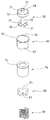
도 3은 본 발명의 제1실시예의 감온 펠릿형 온도 퓨즈의 케이싱 내부에 조립된 부품들을 분리하여 도시한 사시도이다.
도 4는 본 발명의 제2실시예에 따른 온도 퓨즈의 스위치 온 상태의 길이방향 조립단면도이고,
도 5는 도 4의 온도 퓨즈의 스위치 오프 상태의 길이방향 조립단면도이다.
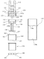
도 6은 본 발명의 제2실시예에 따른 온도 퓨즈의 분리 사시도이다.
10b, 110b: 단턱 11, 111: 제1리이드선,
12, 112: 제2리이드선 13, 111a, 112a: 단자
20,120: 절연 부시 21, 121: 관통구멍
22, 122: 포켓 30,130: 가동 단자
31,131: 접촉단자부 32, 132: 접촉면
33, 133: 안내부 34,134: 상단면
35,135: 연장부 36, 136: 받침판
37, 137: 홈 40, 140: 스프링
51, 151: 제1감온 펠릿부 52, 152: 제2감온 펠릿부
60, 160: 라이닝 튜브 61,161: 플랜지부
62,162: 관통구멍 70,170: 지지관
71,171: 상단부 80,180: 스페이서
81,181: 홈 123: 상부 절연부
124: 하부 절연부 125: 가이드봉
133a: 안내구멍 S: 실링재
Claims (10)
- 유기화합물로 성형되고, 일정한 작동온도 이상에서 용융되면서 형태가 붕괴되는 감온 펠릿;
상기 감온 펠릿을 내부에 수용하도록 한쪽 선단은 개방되며 다른 쪽 선단에는 바닥(10a)으로 막혀 있는 금속제 케이싱(10);
상기 케이싱(10)과 통전되도록 케이싱(10)의 바닥(10a)에 결합된 제1리이드선(11);
상기 제1리이드선(11)과 대향하여 일렬로 배치되게 상기 케이싱(10)의 개방된 선단측에 고정된 절연 부시(20)를 관통하여 상기 케이싱(10)의 내부로 연장되게 설치된 제2리이드선(12);
상기 케이싱(10) 내부에 케이싱(10)의 길이방향으로 슬라이드 이동가능하게 설치되고 상단에는 상기 제2리이드선(12)과 접촉 또는 분리되는 접촉단자부(31)와 상기 슬라이드 이동을 안내하는 안내부(33)를 구비한 가동 단자; 및
상기 감온 펠릿이 일정한 작동온도에서 용융되어 형태가 붕괴될 때 상기 가동 단자의 접촉단자부(31)가 상기 제2리이드선(12)에서 분리되는 방향으로 상기 가동 단자에 탄성력을 가하는 스프링(40)을 포함한 감온 펠릿형 온도 퓨즈에 있어서,
상기 감온 펠릿은 상기 작동온도 이하에서는 상기 스프링(40)을 압축상태로 고정하고 있다가 상기 작동 온도 이상에서는 용융되어, 스프링(40)을 고정해제하도록, 스프링(40) 주위를 둘러싼 상태로 고화된 제1감온 펠릿부(51)를 포함한 것을 특징으로 하는 감온 펠릿형 온도 퓨즈. - 제1항에 있어서,
상기 제1감온 펠릿부(51)가 용융되는 소정의 작동 온도 이하에서는 상기 가동 단자의 접촉단자부(31)와 상기 제2리이드선(12)이 접촉한 상태를 유지하도록 상기 가동 단자의 하단을 케이싱(10)의 바닥(10a)에 대하여 지지하고, 상기 제1감온 펠릿부(51)가 용융되는 상기 작동 온도에 도달하면 용융되면서 상기 가동 단자를 지지해제하여 상기 가동 단자의 접촉단자부(31)가 상기 제2리이드선(12)에서 분리되게 하는 제2감온 펠릿부(52)를 더 포함하고,
상기 제2감온 펠릿부(52)는 상기 제1감온 펠릿부(51)와 동일한 조건에서 용융되도록 제1감온 펠릿부(51)와 동일한 조성물로 이루어진 것을 특징으로 하는 감온 펠릿형 온도 퓨즈. - 제2항에 있어서,
상기 케이싱(10)의 내측 바닥(10a)측에 배치되는 지지관과, 상기 지지관의 상측에 동축으로 적층배치되고 상기 케이싱(10)과 통전되게 결합되는 금속제의 라이닝 튜브(60)를 더 포함하고,
상기 라이닝 튜브(60)는 상단에 상기 케이싱(10)과 통전되게 케이싱(10)의 내측벽과 접촉하는 플랜지부(61)를 구비하고, 상기 플랜지부(61)는 상기 가동 단자의 접촉단자부(31)가 관통하도록 관통구멍(62)이 형성되며, 상기 플랜지부(61)의 저면에 상기 가동 단자의 안내부(33)의 상단면(34)과 맞닿을 때 가동 단자와 라이닝 튜브(60)는 서로 통전되며,
상기 가동 단자는 하부가 상기 지지관(70)의 관통구멍을 관통하여 상기 지지관(70)의 내부로 연장되고, 이 가동 단자의 하부의 끝단에는 상기 스프링(40)의 하단을 지지하는 받침판(36)이 구비되며,
상기 스프링(40)은 상기 가동 단자의 하부에 끼워져 상기 지지관(70)의 상단의 저면과 상기 가동 단자의 받침판(36) 사이에 탄력적으로 설치되어, 상기 가동 단자를 접촉단자부(31)가 제2리이드선(12)에서 분리되는 방향으로 편향시키는 것을 특징으로 하는 감온 펠릿형 온도 퓨즈. - 제3항에 있어서,
상기 제2감온 펠릿부(52)는 상기 받침판(36)의 하부에 배치되어 상단면이 상기 받침판(36)의 하단을 지지하는 것을 특징으로 하는 것을 특징으로 하는 감온 펠릿형 온도 퓨즈. - 제4항에 있어서,
상기 케이싱(10)의 바닥(10a)에는 상기 지지관(70)의 하단이 상기 케이싱(10)의 바닥(10a)에서 일정한 공간을 형성하도록 상기 지지관(70)의 하단을 지지하는 스페이서(80)가 더 구비되고,
상기 스페이서(80)는 상기 지지관(70)의 제2감온 펠릿부(52)가 용융될 때 용융물이 지지관(70)에서 배출되게 허용하는 홈(81)이 적어도 하나 이상 구비된 것을 특징으로 하는 감온 펠릿형 온도 퓨즈. - 감온 펠릿형 온도 퓨즈에 있어서,
유기화합물로 성형되고, 일정한 작동온도 이상에서는 용융되면서 형태가 붕괴되는 감온 펠릿;
상기 감온 펠릿을 내부에 수용하도록 한쪽 선단은 개방되며 다른 쪽 선단에는 바닥(110a)으로 막혀 있는 금속제 케이싱(110);
상기 케이싱(110)과 절연되도록 상기 케이싱(110)의 개방된 선단측에 고정된 절연 부시(120)를 관통하여 상기 케이싱(110)의 내부로 연장되게 설치된 제1리이드선(111);
상기 제1리이드선(111)과 횡방향으로 일정한 간격을 두고 나란하게 배치되고, 상기 절연 부시(120)를 관통하여 상기 케이싱(110)의 내부로 연장되게 설치된 제2리이드선(112);
상기 케이싱(110) 내부에 케이싱(110)의 길이방향으로 슬라이드 이동가능하게 설치되고, 상기 제1리이드선(111)과 제2리이드선(112)에, 동시에 접촉 또는 분리되는 접촉단자부(131)와, 슬라이드 이동을 안내하는 안내부(133)를 구비한 가동 단자(130); 및
상기 감온 펠릿이 일정한 작동온도에서 용융되어 형태가 붕괴될 때 상기 가동 단자(130)의 접촉단자부(131)가 상기 제1리이드선(111)과 제2리이드선(112)에서 분리되는 방향으로 상기 가동 단자(130)에 탄성 편향력을 가하는 스프링(140)을 포함하고,
상기 감온 펠릿은 상기 작동온도 이하에서는 상기 스프링(140)을 압축상태로 고정하고 있다가 상기 작동 온도 이상에서는 용융되어, 스프링(140)을 고정해제하도록, 스프링(140) 주위를 둘러싼 상태로 고화된 제1감온 펠릿부(151)를 포함한 것을 특징으로 하는 감온 펠릿형 온도 퓨즈. - 제6항에 있어서,
상기 작동 온도 이하에서는 상기 가동 단자(130)의 접촉단자부(131)가 상기 제1리이드선(111) 및 제2리이드선(112)과의 접촉 상태를 유지하도록 상기 가동 단자(130)의 저면을 케이싱(110)의 바닥(110a)에 대하여 지지하고, 상기 제1감온 펠릿부(151)가 용융되는 상기 작동 온도에 도달하면, 제1감온 펠릿부(151)와 함께 용융되면서 상기 가동 단자(130)를 지지해제하여 상기 가동 단자(130)의 접촉단자부(131)가 상기 제1리이드선(111) 및 제2리이드선(112)에서 분리되게 하는 제2감온 펠릿부(152)를 더 포함하고,
상기 제2감온 펠릿부(152)는 상기 제1감온 펠릿부(151)와 동일한 조건에서 용융되도록 제1감온 펠릿부(151)와 동일한 조성물로 이루어진 것을 특징으로 하는 감온 펠릿형 온도 퓨즈. - 제7항에 있어서,
상기 케이싱(110)의 내측 바닥(110a)측에 배치되고 상단 지지부를 구비한 지지관과, 상기 지지관의 상측에 동축으로 적층배치되고 상단에 상기 케이싱(110)과 통전되게 접촉하는 플랜지부(161)를 구비한 금속제의 라이닝 튜브(160)를 더 포함하고,
상기 가동 단자(130)는 중심방향을 따라 상기 지지관의 내측으로 연장된 연장부(135)와, 상기 연장부(135)의 하단에 받침판(136)을 구비하고,
상기 스프링(140)은 상기 가동 단자(130)의 연장부(135) 둘레에 끼워져 설치되어 상기 지지관의 상단 지지부의 저면과 상기 가동 단자(130)의 받침판(136) 사이에 탄력적으로 설치되어, 상기 가동 단자(130)를 리이드선(111,112)들과 통전되지 않도록 분리되는 방향으로 편향시키는 것을 특징으로 하는 감온 펠릿형 온도 퓨즈. - 제8항에 있어서,
상기 제2감온 펠릿부(152)는 상기 받침판(136)의 하부에 배치되어 상단면이 상기 받침판(136)의 하단을 지지하는 것을 특징으로 하는 것을 특징으로 하는 감온 펠릿형 온도 퓨즈. - 제9항에 있어서,
상기 케이싱(110)의 바닥(110a)에는 상기 지지관의 하단이 상기 케이싱(110)의 바닥(110a)에서 일정한 공간을 형성하도록 상기 지지관의 하단을 지지하는 스페이서(180)가 더 구비되고, 상기 스페이서(180)는 상기 지지관의 제2감온 펠릿부(152)가 용융될 때 용융물이 지지관에서 배출되게 허용하는 홈(181)이 적어도 하나 이상 구비된 것을 특징으로 하는 감온 펠릿형 온도 퓨즈.
Priority Applications (2)
| Application Number | Priority Date | Filing Date | Title |
|---|---|---|---|
| PCT/KR2015/012277 WO2017086491A1 (ko) | 2015-11-16 | 2015-11-16 | 감온 펠릿형 온도 퓨즈 |
| KR1020150160294A KR101752696B1 (ko) | 2015-11-16 | 2015-11-16 | 감온 펠릿형 온도 퓨즈 |
Applications Claiming Priority (1)
| Application Number | Priority Date | Filing Date | Title |
|---|---|---|---|
| KR1020150160294A KR101752696B1 (ko) | 2015-11-16 | 2015-11-16 | 감온 펠릿형 온도 퓨즈 |
Publications (2)
| Publication Number | Publication Date |
|---|---|
| KR20170056897A true KR20170056897A (ko) | 2017-05-24 |
| KR101752696B1 KR101752696B1 (ko) | 2017-07-11 |
Family
ID=58719203
Family Applications (1)
| Application Number | Title | Priority Date | Filing Date |
|---|---|---|---|
| KR1020150160294A Active KR101752696B1 (ko) | 2015-11-16 | 2015-11-16 | 감온 펠릿형 온도 퓨즈 |
Country Status (2)
| Country | Link |
|---|---|
| KR (1) | KR101752696B1 (ko) |
| WO (1) | WO2017086491A1 (ko) |
Cited By (2)
| Publication number | Priority date | Publication date | Assignee | Title |
|---|---|---|---|---|
| KR20190017459A (ko) * | 2017-08-11 | 2019-02-20 | 한국알프스 주식회사 | 파워 윈도우 스위치용 과전류 보호장치 및 이를 포함하는 파워 윈도우 스위치 |
| WO2020080584A1 (ko) * | 2018-10-19 | 2020-04-23 | 동양전자(주) | 감온 펠릿형 온도 퓨즈 |
Families Citing this family (2)
| Publication number | Priority date | Publication date | Assignee | Title |
|---|---|---|---|---|
| US11411339B2 (en) * | 2020-03-24 | 2022-08-09 | R.S.M. Electron Power, Inc. | Apparatus and method for modifying an electrical circuit |
| CN112201533A (zh) * | 2020-10-15 | 2021-01-08 | 屈风景 | 一种用于笔记本电源线的自动断电装置 |
Family Cites Families (5)
| Publication number | Priority date | Publication date | Assignee | Title |
|---|---|---|---|---|
| US4167724A (en) * | 1977-11-14 | 1979-09-11 | Mccaughna James R | Thermal switches |
| JP2004119255A (ja) * | 2002-09-27 | 2004-04-15 | Nec Schott Components Corp | 温度ヒューズ |
| GB2471869B (en) * | 2009-07-15 | 2012-04-25 | Vishay Resistors Belgium Bvba | Thermal switch |
| JP4714292B2 (ja) * | 2009-11-30 | 2011-06-29 | 宝商株式会社 | 感温ペレット式温度ヒューズ |
| KR101435955B1 (ko) * | 2014-04-23 | 2014-09-02 | 동양전자 주식회사 | 감온 펠릿형 온도 퓨즈 |
-
2015
- 2015-11-16 WO PCT/KR2015/012277 patent/WO2017086491A1/ko not_active Ceased
- 2015-11-16 KR KR1020150160294A patent/KR101752696B1/ko active Active
Cited By (3)
| Publication number | Priority date | Publication date | Assignee | Title |
|---|---|---|---|---|
| KR20190017459A (ko) * | 2017-08-11 | 2019-02-20 | 한국알프스 주식회사 | 파워 윈도우 스위치용 과전류 보호장치 및 이를 포함하는 파워 윈도우 스위치 |
| WO2020080584A1 (ko) * | 2018-10-19 | 2020-04-23 | 동양전자(주) | 감온 펠릿형 온도 퓨즈 |
| US11456141B2 (en) | 2018-10-19 | 2022-09-27 | Dong-Yang Electronics Co., Ltd. | Temperature sensitive pellet type thermal fuse |
Also Published As
| Publication number | Publication date |
|---|---|
| WO2017086491A1 (ko) | 2017-05-26 |
| KR101752696B1 (ko) | 2017-07-11 |
Similar Documents
| Publication | Publication Date | Title |
|---|---|---|
| US5831507A (en) | Dual-functional fuse unit that is responsive to electric current and ambient temperature | |
| KR101753635B1 (ko) | 감온 펠릿형 온도 퓨즈 | |
| US4276532A (en) | Thermal fuse | |
| KR101752696B1 (ko) | 감온 펠릿형 온도 퓨즈 | |
| KR101546277B1 (ko) | 소형 안전 스위치 | |
| KR101435955B1 (ko) | 감온 펠릿형 온도 퓨즈 | |
| US20170345603A1 (en) | Temperature-sensitive pellet type thermal fuse | |
| US4210893A (en) | Thermal cut-off fuse | |
| US10049795B2 (en) | Surge protection device, comprising at least one surge arrester and one thermally trippable switching device connected in series with the surge arrester | |
| KR101916851B1 (ko) | 감온 펠릿형 온도 퓨즈 | |
| US20160336136A1 (en) | Integral complex safety apparatus | |
| KR20160134492A (ko) | 일체형 복합 안전장치 | |
| US4126845A (en) | Temperature responsive current interrupter | |
| JPS6026432Y2 (ja) | スイツチ装置 | |
| US20040100354A1 (en) | Thermal fuse containing bimetallic sensing element | |
| US11456141B2 (en) | Temperature sensitive pellet type thermal fuse | |
| US20240258053A1 (en) | Temperature-dependent switch | |
| US4179679A (en) | Thermal switch | |
| TWI854976B (zh) | 熱保護裝置 | |
| US4246561A (en) | Temperature-responsive electrical switch with sliding contact | |
| KR101458720B1 (ko) | 열적으로 퓨징되는 mov 장치 및 이를 포함하는 회로 | |
| KR20120085725A (ko) | 열 스위치 | |
| CN113035664A (zh) | 一种绝缘线绕模压型温度熔断电阻器 | |
| US4135177A (en) | Thermal protective switch | |
| CN107204250A (zh) | 继电器 |
Legal Events
| Date | Code | Title | Description |
|---|---|---|---|
| A201 | Request for examination | ||
| PA0109 | Patent application |
St.27 status event code: A-0-1-A10-A12-nap-PA0109 |
|
| PA0201 | Request for examination |
St.27 status event code: A-1-2-D10-D11-exm-PA0201 |
|
| P22-X000 | Classification modified |
St.27 status event code: A-2-2-P10-P22-nap-X000 |
|
| E902 | Notification of reason for refusal | ||
| PE0902 | Notice of grounds for rejection |
St.27 status event code: A-1-2-D10-D21-exm-PE0902 |
|
| E13-X000 | Pre-grant limitation requested |
St.27 status event code: A-2-3-E10-E13-lim-X000 |
|
| P11-X000 | Amendment of application requested |
St.27 status event code: A-2-2-P10-P11-nap-X000 |
|
| P13-X000 | Application amended |
St.27 status event code: A-2-2-P10-P13-nap-X000 |
|
| E701 | Decision to grant or registration of patent right | ||
| PE0701 | Decision of registration |
St.27 status event code: A-1-2-D10-D22-exm-PE0701 |
|
| PG1501 | Laying open of application |
St.27 status event code: A-1-1-Q10-Q12-nap-PG1501 |
|
| GRNT | Written decision to grant | ||
| PR0701 | Registration of establishment |
St.27 status event code: A-2-4-F10-F11-exm-PR0701 |
|
| PR1002 | Payment of registration fee |
St.27 status event code: A-2-2-U10-U11-oth-PR1002 Fee payment year number: 1 |
|
| PG1601 | Publication of registration |
St.27 status event code: A-4-4-Q10-Q13-nap-PG1601 |
|
| P22-X000 | Classification modified |
St.27 status event code: A-4-4-P10-P22-nap-X000 |
|
| R18-X000 | Changes to party contact information recorded |
St.27 status event code: A-5-5-R10-R18-oth-X000 |
|
| PR1001 | Payment of annual fee |
St.27 status event code: A-4-4-U10-U11-oth-PR1001 Fee payment year number: 4 |
|
| PR1001 | Payment of annual fee |
St.27 status event code: A-4-4-U10-U11-oth-PR1001 Fee payment year number: 5 |
|
| PR1001 | Payment of annual fee |
St.27 status event code: A-4-4-U10-U11-oth-PR1001 Fee payment year number: 6 |
|
| PR1001 | Payment of annual fee |
St.27 status event code: A-4-4-U10-U11-oth-PR1001 Fee payment year number: 7 |
|
| PR1001 | Payment of annual fee |
St.27 status event code: A-4-4-U10-U11-oth-PR1001 Fee payment year number: 8 |
|
| PR1001 | Payment of annual fee |
St.27 status event code: A-4-4-U10-U11-oth-PR1001 Fee payment year number: 9 |
|
| U11 | Full renewal or maintenance fee paid |
Free format text: ST27 STATUS EVENT CODE: A-4-4-U10-U11-OTH-PR1001 (AS PROVIDED BY THE NATIONAL OFFICE) Year of fee payment: 9 |