KR20170058024A - Storage tank for oil - Google Patents
Storage tank for oil Download PDFInfo
- Publication number
- KR20170058024A KR20170058024A KR1020150161700A KR20150161700A KR20170058024A KR 20170058024 A KR20170058024 A KR 20170058024A KR 1020150161700 A KR1020150161700 A KR 1020150161700A KR 20150161700 A KR20150161700 A KR 20150161700A KR 20170058024 A KR20170058024 A KR 20170058024A
- Authority
- KR
- South Korea
- Prior art keywords
- frp
- storage tank
- coating film
- layer
- oil
- Prior art date
- Legal status (The legal status is an assumption and is not a legal conclusion. Google has not performed a legal analysis and makes no representation as to the accuracy of the status listed.)
- Granted
Links
Images


Classifications
-
- B—PERFORMING OPERATIONS; TRANSPORTING
- B65—CONVEYING; PACKING; STORING; HANDLING THIN OR FILAMENTARY MATERIAL
- B65D—CONTAINERS FOR STORAGE OR TRANSPORT OF ARTICLES OR MATERIALS, e.g. BAGS, BARRELS, BOTTLES, BOXES, CANS, CARTONS, CRATES, DRUMS, JARS, TANKS, HOPPERS, FORWARDING CONTAINERS; ACCESSORIES, CLOSURES, OR FITTINGS THEREFOR; PACKAGING ELEMENTS; PACKAGES
- B65D90/00—Component parts, details or accessories for large containers
- B65D90/02—Wall construction
-
- B—PERFORMING OPERATIONS; TRANSPORTING
- B65—CONVEYING; PACKING; STORING; HANDLING THIN OR FILAMENTARY MATERIAL
- B65D—CONTAINERS FOR STORAGE OR TRANSPORT OF ARTICLES OR MATERIALS, e.g. BAGS, BARRELS, BOTTLES, BOXES, CANS, CARTONS, CRATES, DRUMS, JARS, TANKS, HOPPERS, FORWARDING CONTAINERS; ACCESSORIES, CLOSURES, OR FITTINGS THEREFOR; PACKAGING ELEMENTS; PACKAGES
- B65D90/00—Component parts, details or accessories for large containers
- B65D90/02—Wall construction
- B65D90/04—Linings
-
- B—PERFORMING OPERATIONS; TRANSPORTING
- B65—CONVEYING; PACKING; STORING; HANDLING THIN OR FILAMENTARY MATERIAL
- B65D—CONTAINERS FOR STORAGE OR TRANSPORT OF ARTICLES OR MATERIALS, e.g. BAGS, BARRELS, BOTTLES, BOXES, CANS, CARTONS, CRATES, DRUMS, JARS, TANKS, HOPPERS, FORWARDING CONTAINERS; ACCESSORIES, CLOSURES, OR FITTINGS THEREFOR; PACKAGING ELEMENTS; PACKAGES
- B65D90/00—Component parts, details or accessories for large containers
- B65D90/02—Wall construction
- B65D90/06—Coverings, e.g. for insulating purposes
-
- B—PERFORMING OPERATIONS; TRANSPORTING
- B65—CONVEYING; PACKING; STORING; HANDLING THIN OR FILAMENTARY MATERIAL
- B65D—CONTAINERS FOR STORAGE OR TRANSPORT OF ARTICLES OR MATERIALS, e.g. BAGS, BARRELS, BOTTLES, BOXES, CANS, CARTONS, CRATES, DRUMS, JARS, TANKS, HOPPERS, FORWARDING CONTAINERS; ACCESSORIES, CLOSURES, OR FITTINGS THEREFOR; PACKAGING ELEMENTS; PACKAGES
- B65D90/00—Component parts, details or accessories for large containers
- B65D90/48—Arrangements of indicating or measuring devices
- B65D90/50—Arrangements of indicating or measuring devices of leakage-indicating devices
-
- B—PERFORMING OPERATIONS; TRANSPORTING
- B65—CONVEYING; PACKING; STORING; HANDLING THIN OR FILAMENTARY MATERIAL
- B65D—CONTAINERS FOR STORAGE OR TRANSPORT OF ARTICLES OR MATERIALS, e.g. BAGS, BARRELS, BOTTLES, BOXES, CANS, CARTONS, CRATES, DRUMS, JARS, TANKS, HOPPERS, FORWARDING CONTAINERS; ACCESSORIES, CLOSURES, OR FITTINGS THEREFOR; PACKAGING ELEMENTS; PACKAGES
- B65D2590/00—Component parts, details or accessories for large containers
- B65D2590/02—Wall construction
- B65D2590/026—Special coating or treatment of the external surface
Landscapes
- Engineering & Computer Science (AREA)
- Mechanical Engineering (AREA)
- Examining Or Testing Airtightness (AREA)
Abstract
본 발명에 의하면, 유류 저장탱크에 있어서, 유류를 저장하기 위한 금속재로 이루어진 금속 탱크(10), 금속 탱크(10)의 외주면에 frp 수지로 코팅된 제1 frp 코팅막(20), 제1 frp 코팅막(20)의 외주면에 대하여 누유 감지하며 누유를 방지하기 위한 누유 감지층(30), 및 누유 감지층(30)의 외주면에 frp 수지로 코팅된 제2 frp 코팅막(40)으로 이루어진 유류 저장탱크가 제공된다.According to the present invention, in the oil storage tank, a metal tank 10 made of a metal material for storing oil, a first frp coating film 20 coated with frp resin on the outer circumferential surface of the metal tank 10, And a second frp coating film (40) coated on the outer circumferential surface of the oil leakage detection layer (30) with frp resin, the oil storage tank (30) / RTI >
Description
본 발명은 지하에 매설되는 유류 저장탱크에 관한 것으로서, 보다 상세하게는 지하에 매설시에 발생될 수 있는 누유를 효율적으로 감지함과 동시에 저장탱크의 내구성을 향상시킬 수 있는 유류 저장탱크에 관한 것이다.BACKGROUND OF THE
일반적으로 주유소나 저유소에서 사용되고 있는 유류저장탱크는 철재로 된 몸체의 외면에 방청도장을 하여 이를 지하에 매설하여 사용하는 것이 대부분이었다. Generally, most of oil storage tanks used in gas stations or petrol stations are rustproof painted on the outer surface of steel body and buried underground.
그러나 이러한 형태의 유류저장탱크는 외부의 온도변화나 각종 화학적 자극이나 반응 또는 기계적 외압등에 의하여 방청도장층이 회손되어 철재의 몸체가 외부 화경에 노출됨으로써 탱크의 균열이나 부식으로 이어져, 저장된 유류의 누출로 인한 재산적 손해와 이로 인한 심각한 환경오염을 야기시켜 큰 문제점으로 되고 있다. However, in this type of oil storage tank, the rustproof paint layer is pulled by external temperature change, various chemical stimuli, reaction or mechanical external pressure, and the body of the iron is exposed to the outside diameter of the oil storage tank, leading to cracking or corrosion of the tank, Resulting in property damage and serious environmental pollution.
또한 탱크의 누유감지를 위한 별도의 장치가 없어서, 유류의 누출이 심각한 상태로 진행된 후에야 발견이 가능하기 때문에 누유 여부를 손쉽게 검사할 수 있는 기술이 요구되고 있다.In addition, there is no separate device for leakage detection of the tank, so that it is possible to detect the leakage of the oil only after the leakage has proceeded to a serious state.
이와 관련하여 실용신안등록 제20-0354097호에 의하면, 도 1에 도시된 바와 같이, 철재탱크에 대하여 분리막을 형성한 후에 분리막 상에 FRP 탱크를 구비하는 기술이 시도됨으로써, 철재탱크의 부식 등으로 인한 누유를 1차적으로 방지할 수 FRP 탱크에서 방지할 수 있으나, 분리막 내에 온습도 변호에 따른 철재탱크의 부식을 근본적으로 해결할 수 없는 문제점이 있다. In this regard, according to the Utility Model Registration No. 20-0354097, as shown in FIG. 1, attempts have been made to provide a FRP tank on a separation membrane after forming a separation membrane for a steel tank, There is a problem in that corrosion of the steel tank due to the protection of the temperature and humidity can not be fundamentally solved in the separator.
더욱이, 철재탱크와 FRP 탱크 사이의 분리막의 특성상 FRP가 철재탱크에 대하여 긴밀하게 형성될 수 없으며, 그에 따라 내구성과 견고성이 비교적 저하되는 문제점을 가지고 있다.In addition, due to the nature of the separator between the steel tank and the FRP tank, the FRP can not be formed tightly against the steel tank, thereby resulting in a relatively low durability and rigidity.
따라서 이러한 문제점을 해결할 수 있는 기술의 개발이 요구되고 있다.Therefore, development of a technique capable of solving such a problem is required.
따라서 본 발명의 목적은 유류 저장탱크에 있어서 철재탱크의 부식 등으로 인한 내구성을 향상시킬 수 있는 유류 저장탱크를 제공하는 것이다.Accordingly, it is an object of the present invention to provide an oil storage tank capable of improving durability due to corrosion of an iron tank in a oil storage tank.
또한 본 발명의 다른 목적은 유류 저장탱크의 누유 감지를 위한 분리막의 형성에 따라 발생될 수 있는 FRP 탱크와 철재 탱크 사이의 긴밀성을 향상시킬 수 있는 유류 저장탱크를 제공하는 것이다.Another object of the present invention is to provide a fuel storage tank capable of improving the tightness between the FRP tank and the steel tank, which can be generated according to the formation of the separation membrane for oil leakage detection of the oil storage tank.
본 발명에 의하면, 유류 저장탱크에 있어서, 유류를 저장하기 위한 금속재로 이루어진 금속 탱크(10), 금속 탱크(10)의 외주면에 frp 수지로 코팅된 제1 frp 코팅막(20), 제1 frp 코팅막(20)의 외주면에 대하여 누유 감지하며 누유를 방지하기 위한 누유 감지층(30), 및 누유 감지층(30)의 외주면에 frp 수지로 코팅된 제2 frp 코팅막(40)으로 이루어진 유류 저장탱크가 제공된다.According to the present invention, in the oil storage tank, a
여기서, 제1 frp 코팅막(20)은 금속 탱크(10)의 외주면에 대하여 샌드브라스트나 프라이머를 도포한 후에 frp 수지를 코팅하여 이루어지거나, 직접 제1 frp 코팅막(20)이 금속 탱크(10) 상에 대하여 가압 도포되는 것이 바람직하다.Here, the first
한편, 누유 감지층(30)의 내외면은 frp 수지에 대하여 계면활성을 가지는 분리막으로 이루어지는 것이 바람직하다.On the other hand, it is preferable that the inner and outer surfaces of the
또한, 누유 감지층(30)은 격벽의 구조물로 이루어지는 것이 바람직하다.Further, it is preferable that the
또한, 누유 감지층(30)의 격벽 구조물은 그물망의 형태로 이루어지는 것이 바람직하다.Further, it is preferable that the barrier structure of the
또한, 상기 그물망의 외주연은 frp 수지층으로 코팅되는 frp 코팅층(32)을 더 구비하는 것이 바람직하다.In addition, it is preferable that the outer periphery of the mesh network further includes a
금속 탱크(10)의 외부에 구비되는 제1 frp 코팅막(20), 누유 감지층(30) 및 제2 frp 코팅막(40)이 동일한 화학적 성질의 특성으로 인하여 유류 탱크가 보다 긴밀하게 형성되어 내구성을 보다 효율적으로 향상시킬 수 있으며, 동일한 화학적 특성으로 인하여 작업성을 향상시킬 수 있다.The first
도 1은 종래 유류 저장탱크의 개략적인 사시도이다.
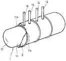
도 2는 본 발명의 바람직한 실시예에 따른 유류 저장탱크의 개략적인 부분 절개 사시도이다.
도 3은 본 발명의 바람직한 변형예에 따른 유류 저장탱크의 개략적인 부분 절개 사시도이다.
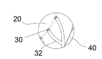
도 4는 도 3의 A 부분에 대한 확대도이다.1 is a schematic perspective view of a conventional oil storage tank.
2 is a schematic partial cutaway perspective view of a oil storage tank according to a preferred embodiment of the present invention.
3 is a schematic partial cutaway perspective view of a oil storage tank according to a preferred version of the present invention.
4 is an enlarged view of a portion A in Fig.
이하, 첨부된 도면을 참조하면서, 본 발명의 바람직한 실시예에 따른 유류 저장탱크에 대하여 상세히 설명하기로 한다.DETAILED DESCRIPTION OF THE PREFERRED EMBODIMENT Hereinafter, a preferred embodiment of the present invention will be described in detail with reference to the accompanying drawings.
도 2는 본 발명의 바람직한 실시예에 따른 유류 저장탱크의 개략적인 부분 절개 사시도이다.2 is a schematic partial cutaway perspective view of a oil storage tank according to a preferred embodiment of the present invention.
도 2에 도시된 바와 같이, 본 발명의 바람직한 실시예에 따른 유류 저장탱크는 유류를 저장하기 위한 금속재로 이루어진 금속 탱크(10), 금속 탱크(10)의 외주면에 frp 수지로 코팅된 제1 frp 코팅막(20), 제1 frp 코팅막(20)의 외주면에 대하여 누유 감지를 위한 누유 감지층(30), 및 누유 감지층(30)의 외주면에 frp 수지로 코팅된 제2 frp 코팅막(40)으로 이루어진 유류 저장탱크가 제공된다.2, the oil storage tank according to the preferred embodiment of the present invention includes a
금속 탱크(10)는 유류를 저장하기 위한 통상의 원통형 탱크로 이루어진다.The
제1 frp 코팅막(20)은 금속 탱크(10)의 외주면에 대하여 샌드브라스트나 프라이머를 도포한 후에 frp 수지를 코팅하여 이루어져도 좋으나, 직접 제1 frp 코팅막(20)이 금속 탱크(10) 상에 대하여 가압 도포되어도 좋다.The first
누유 감지층(30)은 제1 frp 코팅막(20) 상에 누유를 감지하기 위한 센서를 포함하는 누유 감지층으로 형성된다.The
한편, 누유 감지층(30)은 금속 탱크(10)와 제1 frp 코팅막(20)의 파손으로 인한 누유를 임시적으로 누유 방지하기 위한 공간을 제공하는 이격층으로 이루어지는 것이 바람직하다. 이 때 누유 감지층(30)의 내외면은 frp 수지에 대하여 계면활성을 가지는 분리막으로 이루어지는 것이 바람직하다.The
누유 감지층(30)을 이루는 분리막 상에 frp 수지로 이루어진 제2 frp 코팅막(40)이 도포된다.A second
이 때, 누유 감지층(30)을 이루는 분리막은 제1 frp 코팅막(20)의 frp 수지에 대한 계면 활성상태를 가지고 있기 때문에 제1 frp 코팅막(20)과 제2 frp 코팅막(40)이 누유 감지층(30)인 분리막을 매개하여 긴밀한 계면 접착상태를 유지할 수 있다. 그에 따라 금속 탱크(10)의 외주면에 도포된 제1 frp 코팅막(20), 누유 감지층(30)인 분리막 및 제2 frp 코팅막(40)이 서로 긴밀하게 접합상태를 유지함으로써 금속 탱크(10)의 누유 발생 방지를 위한 내구성을 향상시킬 수 있다.At this time, since the separation membrane constituting the
한편, 본 발명의 바람직한 변형예에 따른 유류 저장탱크에 의하면, 도 2에 도시된 바와 같이, 누유 감지층(30)은 격벽의 구조물로 이루어질 수도 있다.According to a preferred embodiment of the present invention, as shown in FIG. 2, the oil
본 발명의 바람직한 변형예에 따른 유류 저장탱크에 있어서 전술한 실시예와 동일한 구성은 동일한 참조번호로 나타내며, 그에 대한 설명은 생략하기로 한다.In the oil storage tank according to a preferred modification of the present invention, the same components as those of the above-described embodiment are denoted by the same reference numerals, and a description thereof will be omitted.
본 발명의 바람직한 변형예에 의하면, 누유 감지층(30)은 누유 발생시 임시적으로 누유 방지를 위한 공간을 제공함에 있어서, 제1 frp 코팅막(20)과 제2 frp 코팅막(40) 사이의 보다 긴밀한 접합상태를 형성하기 위하여, 누유 감지층(30)은 격벽의 구조물로 이루어진다. 이 때, 누유 감지층(30)의 격벽 구조물은, 도 2에 도시된 바와 같이, 그물망의 형태로 이루어지는 것이 바람직하다.According to a preferred modification of the present invention, the
누유 감지층(30)의 격벽 구조물은 그물망의 형태로 이루어져 제1 frp 코팅막(20)의 외주면에 감싸는 형태로 구비되며, 상기 그물망의 외주연은, 도 4에 도시된 바와 같이, frp 수지층으로 코팅되는 frp 코팅층(32)을 더 구비하는 것이 보다 바람직하다.The barrier layer structure of the
이 때, frp 코팅층(32)의 외주연은 frp 수지층으로 코팅됨으로써, 누유 감지층(30)이 제1 frp 코팅막(20)과 접하는 면과 제2 frp 코팅막(40)과 접하는 면에 각각 frp 수지층으로 코팅되어 노출되는 것이 바람직하다. 이와 같이, 누유 감지층(30)의 외주연이 접하는 제1 frp 코팅막(20)과 제2 frp 코팅막(40)은 동일한 화학적 성질을 가지는 frp 수지층으로 이루어짐으로써, 금속 탱크(10)의 외부에 구비되는 제1 frp 코팅막(20), 누유 감지층(30) 및 제2 frp 코팅막(40)이 동일한 화학적 성질의 특성으로 인하여 유류 탱크가 보다 긴밀하게 형성되어 내구성을 보다 효율적으로 향상시킬 수 있으며, 동일한 화학적 특성으로 인하여 작업성을 향상시킬 수 있다.The outer peripheral edge of the
10: 금속 탱크
20: 제1 frp 코팅막
30: 누유 감지층
32: frp 코팅층
40: 제2 frp 코팅막10: Metal tank
20: First frp coating film
30: Leak detection layer
32: frp coating layer
40: second frp coating film
Claims (6)
유류를 저장하기 위한 금속재로 이루어진 금속 탱크(10);
금속 탱크(10)의 외주면에 frp 수지로 코팅된 제1 frp 코팅막(20);
제1 frp 코팅막(20)의 외주면에 대하여 누유 감지하며 누유를 방지하기 위한 누유 감지층(30); 및
누유 감지층(30)의 외주면에 frp 수지로 코팅된 제2 frp 코팅막(40)으로 이루어진 것을 특징으로 하는 유류 저장탱크.In the oil storage tank,
A metal tank (10) made of a metal material for storing oil;
A first frp coating film (20) coated on the outer circumferential surface of the metal tank (10) with frp resin;
A leakage sensing layer (30) for sensing leakage and preventing leakage of oil onto the outer circumferential surface of the first frp coating film (20); And
And a second frp coating film (40) coated on the outer circumferential surface of the leak detection layer (30) with frp resin.
Priority Applications (1)
| Application Number | Priority Date | Filing Date | Title |
|---|---|---|---|
| KR1020150161700A KR101761169B1 (en) | 2015-11-18 | 2015-11-18 | Storage tank for oil |
Applications Claiming Priority (1)
| Application Number | Priority Date | Filing Date | Title |
|---|---|---|---|
| KR1020150161700A KR101761169B1 (en) | 2015-11-18 | 2015-11-18 | Storage tank for oil |
Publications (2)
| Publication Number | Publication Date |
|---|---|
| KR20170058024A true KR20170058024A (en) | 2017-05-26 |
| KR101761169B1 KR101761169B1 (en) | 2017-07-25 |
Family
ID=59052193
Family Applications (1)
| Application Number | Title | Priority Date | Filing Date |
|---|---|---|---|
| KR1020150161700A Active KR101761169B1 (en) | 2015-11-18 | 2015-11-18 | Storage tank for oil |
Country Status (1)
| Country | Link |
|---|---|
| KR (1) | KR101761169B1 (en) |
Families Citing this family (2)
| Publication number | Priority date | Publication date | Assignee | Title |
|---|---|---|---|---|
| KR102455263B1 (en) | 2022-03-30 | 2022-10-18 | 유재완 | Liquid storage tank inner surface coating device and coating method |
| KR102751527B1 (en) | 2024-08-06 | 2025-01-08 | 박금산 | FRP tank with environmental friendliness |
Family Cites Families (2)
| Publication number | Priority date | Publication date | Assignee | Title |
|---|---|---|---|---|
| JP3831383B2 (en) * | 2004-02-27 | 2006-10-11 | 有限会社小室技研 | Test method for airtight layer formed by attaching rehabilitation material to the inner wall of steel underground tank |
| KR200354097Y1 (en) * | 2004-04-08 | 2004-06-23 | 한성산업(주) | An oil tank having a double wall style |
-
2015
- 2015-11-18 KR KR1020150161700A patent/KR101761169B1/en active Active
Also Published As
| Publication number | Publication date |
|---|---|
| KR101761169B1 (en) | 2017-07-25 |
Similar Documents
| Publication | Publication Date | Title |
|---|---|---|
| CN105556078B (en) | Lid installation component | |
| KR101761169B1 (en) | Storage tank for oil | |
| US12269244B2 (en) | Wall structure monitoring system | |
| CN102226282B (en) | Corrosion resistant method of indoor buried valve of petroleum-gas pipeline engineering valve | |
| CN203743841U (en) | Gas cylinder protection cover, gas cylinder and vehicle | |
| CN204792935U (en) | All -round, ne -leakage lithium cell | |
| CN206973278U (en) | A kind of gas pipeline gas leak detection device | |
| WO2009014773A1 (en) | Underground storage tank for flammable liquids | |
| CN203643096U (en) | Testing and sealing structure for discharging of hydrocarbon in plastic fuel tank | |
| JP2006226472A (en) | Fluid transport hose with elastic seal layer and method for manufacturing the same | |
| CN206218557U (en) | A kind of electric conductivity composite multi-layer storage tank | |
| RU2790736C1 (en) | Method for protecting the surface of vertical tanks using a polymeric soft two-layer liner | |
| CN206798305U (en) | A kind of new type FRP liner cylinder of steel | |
| JP4540431B2 (en) | Leak detection device in double shell tank | |
| KR102018428B1 (en) | Tank having leakage detection function | |
| KR101200072B1 (en) | A device for measuring a fluid pressure | |
| KR102788795B1 (en) | Manufacturing method of insulation valve chamber | |
| US20150028137A1 (en) | Tightly extrusion-coated component and method for producing such a component | |
| CN211231955U (en) | Storage tank conveying pipeline | |
| JP3699466B6 (en) | Rehabilitation structure of steel underground tank | |
| KR200493339Y1 (en) | Rust preventing apparatus of coupler base for assembling of insulation box of liquid cargo tank in vessel | |
| KR20150097065A (en) | Tape type gas detecting sensor | |
| CN110887615B (en) | Valve shell airtight inspection device | |
| CN205534803U (en) | A appurtenance for pipeline wall thickness detects | |
| CN203549140U (en) | Oil filling type through-wall water stop heat pipeline |
Legal Events
| Date | Code | Title | Description |
|---|---|---|---|
| A201 | Request for examination | ||
| PA0109 | Patent application |
Patent event code: PA01091R01D Comment text: Patent Application Patent event date: 20151118 |
|
| PA0201 | Request for examination | ||
| E902 | Notification of reason for refusal | ||
| PE0902 | Notice of grounds for rejection |
Comment text: Notification of reason for refusal Patent event date: 20170110 Patent event code: PE09021S01D |
|
| PG1501 | Laying open of application | ||
| E701 | Decision to grant or registration of patent right | ||
| PE0701 | Decision of registration |
Patent event code: PE07011S01D Comment text: Decision to Grant Registration Patent event date: 20170718 |
|
| GRNT | Written decision to grant | ||
| PR0701 | Registration of establishment |
Comment text: Registration of Establishment Patent event date: 20170719 Patent event code: PR07011E01D |
|
| PR1002 | Payment of registration fee |
Payment date: 20170719 End annual number: 3 Start annual number: 1 |
|
| PG1601 | Publication of registration | ||
| FPAY | Annual fee payment |
Payment date: 20170921 Year of fee payment: 5 |
|
| PR1001 | Payment of annual fee |
Payment date: 20170921 Start annual number: 4 End annual number: 5 |
|
| FPAY | Annual fee payment |
Payment date: 20170925 Year of fee payment: 6 |
|
| PR1001 | Payment of annual fee |
Payment date: 20170925 Start annual number: 6 End annual number: 6 |
|
| PR1001 | Payment of annual fee |
Payment date: 20230719 Start annual number: 7 End annual number: 7 |
|
| PR1001 | Payment of annual fee |
Payment date: 20240513 Start annual number: 8 End annual number: 8 |