KR20170062995A - Vehicle head lamp - Google Patents
Vehicle head lamp Download PDFInfo
- Publication number
- KR20170062995A KR20170062995A KR1020150168878A KR20150168878A KR20170062995A KR 20170062995 A KR20170062995 A KR 20170062995A KR 1020150168878 A KR1020150168878 A KR 1020150168878A KR 20150168878 A KR20150168878 A KR 20150168878A KR 20170062995 A KR20170062995 A KR 20170062995A
- Authority
- KR
- South Korea
- Prior art keywords
- reflector
- lens
- light
- additional
- light source
- Prior art date
- Legal status (The legal status is an assumption and is not a legal conclusion. Google has not performed a legal analysis and makes no representation as to the accuracy of the status listed.)
- Ceased
Links
- 230000003287 optical effect Effects 0.000 claims abstract description 35
- 230000004075 alteration Effects 0.000 claims description 37
- 238000000034 method Methods 0.000 claims description 16
- 230000001678 irradiating effect Effects 0.000 claims 1
- 238000010586 diagram Methods 0.000 description 12
- 230000000903 blocking effect Effects 0.000 description 7
- 230000015572 biosynthetic process Effects 0.000 description 3
- 230000006870 function Effects 0.000 description 3
- 230000008901 benefit Effects 0.000 description 2
- 230000000694 effects Effects 0.000 description 2
- 229920002120 photoresistant polymer Polymers 0.000 description 2
- 230000008569 process Effects 0.000 description 2
- 230000009131 signaling function Effects 0.000 description 2
- 230000001502 supplementing effect Effects 0.000 description 2
- 238000007792 addition Methods 0.000 description 1
- 230000006866 deterioration Effects 0.000 description 1
- 239000011521 glass Substances 0.000 description 1
- 230000006872 improvement Effects 0.000 description 1
- 238000009434 installation Methods 0.000 description 1
- 230000001151 other effect Effects 0.000 description 1
- 230000007480 spreading Effects 0.000 description 1
- 238000011144 upstream manufacturing Methods 0.000 description 1
Images







Classifications
-
- F21S48/10—
-
- F21S48/1208—
-
- F21S48/1305—
-
- F21S48/1388—
-
- F21W2101/10—
Landscapes
- Non-Portable Lighting Devices Or Systems Thereof (AREA)
Abstract
본 발명은 차량용 헤드 램프를 개시한다. 본 발명에 따른 차량용 헤드 램프는 광원, 상기 광원으로부터 출사된 광을 반사하는 리플렉터 및 상기 반사된 광을 굴절시켜 외부로 조사하는 렌즈를 포함하되, 상기 반사된 광이 상기 렌즈의 중심부를 투과할 수 있도록, 상기 렌즈의 광축을 기준으로 상기 광원 및 상기 리플렉터가 상기 광이 투과되는 방향의 반대쪽 하방으로 기울어지게 배치된다.The present invention discloses a headlamp for a vehicle. The headlamp for a vehicle according to the present invention includes a light source, a reflector for reflecting light emitted from the light source, and a lens for refracting the reflected light to irradiate the light to the outside, wherein the reflected light is transmitted through a central portion of the lens , The light source and the reflector are arranged to be inclined downward opposite to the direction in which the light is transmitted with respect to the optical axis of the lens.
Description
본 발명은 차량용 헤드 램프에 관한 것으로, 더욱 상세하게는 외부로 조사되는 광 패턴을 개선하기 위한 차량용 헤드 램프에 관한 것이다.BACKGROUND OF THE
일반적으로 차량은 야간 주행시에 차량 주변에 위치한 대상물을 용이하게 확인하기 위한 조명 기능 및 다른 차량이나 도로 이용자들에게 차량의 주행 상태를 알리기 위한 신호 기능을 가지는 다양한 종류의 차량용 램프를 구비하고 있다.2. Description of the Related Art [0002] Generally, a vehicle is equipped with various types of vehicle lamps having a lighting function for easily confirming an object located in the vicinity of the vehicle at nighttime, and a signal function for notifying other vehicle or road users of the running state of the vehicle.
예를 들어, 헤드 램프 및 포그 램프 등은 주로 조명 기능을 목적으로 하고, 턴 시그널 램프, 테일 램프, 브레이크 램프, 사이드 마커(Side Marker) 등은 주로 신호 기능을 목적으로 한다. 또한, 이러한 차량용 램프는 각 기능을 충분히 발휘하도록 그 설치 기준과 규격에 대해서 법규로 규정되어 있다.For example, head lamps and fog lamps are mainly aimed at lighting functions, while turn signal lamps, tail lamps, brake lamps, side markers and the like are mainly used for signal functions. In addition, such vehicle lamps are prescribed by laws and regulations on installation standards and specifications so that each function can be fully utilized.
이러한 차량용 램프 중 차량이 야간에 주행하거나 터널 등과 같은 어두운 장소를 주행할 때 운전자의 전방 시야가 확보되도록 하는 헤드 램프는 안전 운행을 하는데 있어서 매우 중요한 역할을 하고 있다.Among such lamps, a headlamp which ensures the front view of the driver when the vehicle is traveling at night or in a dark place such as a tunnel is very important for safe driving.
전조등이라고도 하는 헤드 램프(head lamp)는 차량이 진행하는 전방의 진로를 비추는 기능을 하는 조명등으로서, 야간에 대략 전방 100m의 거리에 있는 도로상의 장애물을 확인할 수 있는 밝기를 필요로 하고 있다.A head lamp, also referred to as a headlamp, is an illuminating lamp that illuminates the course ahead of the vehicle and requires brightness to identify obstacles on the road at a distance of about 100 meters from the front at night.
이와 같은 차량용 헤드 램프는 광원에 의해 곧바로 조사된 광 및 반사면을 통해 굴절된 광이 전방방향으로 나아가면서 쉴드 상단의 컷 오프 형성에 의하여 광의 일부가 차단되어 소정의 빔 패턴을 형성한다.In such a headlamp for a vehicle, the light directly irradiated by the light source and the light refracted through the reflecting surface move in the forward direction, and a part of the light is blocked by the cut-off formation at the upper end of the shield to form a predetermined beam pattern.
또한, 차량용 헤드 램프의 비구면 렌즈 외측으로 광 레이가 통과될 때, 푸른색 색수차가 다수 발생함에 따라, 전방을 조명하는 차량용 헤드 램프의 품질 저하가 발생된다.In addition, when the light ray passes through the aspherical surface lens of the vehicle headlamp, a large number of blue chromatic aberrations occur, resulting in deterioration of the quality of the headlamp for illuminating the front of the vehicle.
그리고, 차량용 헤드 램프를 하이 빔 패턴으로 외부에 광을 조사할 때, 차량 전방의 외부로 조사되는 하이 빔 패턴이 전방 수평선을 지향하는 패턴이어서 전방 상향측 시야 확보에는 다소 미비하다는 사용자 요구도 있다.There is also a demand for a user that the high beam pattern irradiated to the outside of the front of the vehicle is a pattern directed to the front horizontal line when the vehicle headlamp is irradiated with light in the outside with a high beam pattern, which is somewhat inferior to securing the forward upward visibility.
따라서, 차량용 헤드 램프에서 발생되는 색수차를 차단할 수 있는 방안이 요 구되며, 더 나아가 차량용 헤드 램프에서 색수차를 차단하면서 차량 전방의 상향측 시야 확보를 더 개선할 필요가 있다.Accordingly, it is required to provide a way to block the chromatic aberration generated in the headlamp for the vehicle, and further, it is necessary to further improve the securing of the upside view of the front of the vehicle while blocking the chromatic aberration in the headlamp for the vehicle.
따라서, 본 발명은 상기의 문제점을 해결하기 위해 창출된 것으로, 본 발명의 과제는 차량용 헤드 램프에서 발생되는 색수차를 차단할 수 있도록 차량용 헤드 램프의 렌즈 중심부로 대부분의 광 레이가 통과되도록 광학 설계된 차량용 헤드 램프를 제공하는 데 있다.SUMMARY OF THE INVENTION Accordingly, it is an object of the present invention to provide a headlamp for a vehicle which is optically designed to allow most optical rays to pass through the center of a lens of a headlamp for a vehicle so as to block chromatic aberration generated in a headlamp for a vehicle. Lamps.
또한, 본 발명의 다른 과제로서, 차량용 헤드 램프에서 발생되는 색수차를 차단하면서 함께 차량 전방의 상향측 시야 확보를 더 개선할 수 있도록 전술한 광학 설계에 차량 전방의 상향감 개선용 광 패턴을 보완하는 추가 반사판 구성이 더 포함된 차량용 헤드 램프를 제공하는 데 있다.Another object of the present invention is to provide an optical design for complementing the upstream light enhancement pattern of the vehicle so as to further improve the securing of the upward visibility of the front of the vehicle while blocking the chromatic aberration generated in the vehicle headlamp The present invention provides a headlamp for a vehicle further comprising an additional reflector structure.
본 발명의 목적은 이상에서 언급한 과제로 제한되지 않으며, 언급되지 않은 또 다른 목적들은 아래의 기재로부터 당업자에게 명확하게 이해될 수 있을 것이다.The objects of the present invention are not limited to the above-mentioned problems, and other objects not mentioned can be clearly understood by those skilled in the art from the following description.
상기 과제를 달성하기 위한 본 발명의 관점에 따른 차량용 헤드 램프는 광원, 상기 광원으로부터 출사된 광을 반사하는 리플렉터 및 상기 반사된 광을 굴절시켜 외부로 조사하는 렌즈를 포함하되, 상기 반사된 광이 상기 렌즈의 중심부를 투과할 수 있도록, 상기 렌즈의 광축을 기준으로 상기 광원 및 상기 리플렉터가 상기 광이 투과되는 방향의 반대쪽 하방으로 기울어지게 배치된다.According to an aspect of the present invention, there is provided a vehicular headlamp including a light source, a reflector for reflecting light emitted from the light source, and a lens for refracting the reflected light to irradiate the reflected light to the outside, The light source and the reflector are arranged to be inclined downwardly opposite to the direction in which the light is transmitted, with respect to the optical axis of the lens so as to be able to transmit the center portion of the lens.
상기 광원의 위치는 상기 렌즈의 광축과 상기 광원의 수직축 간에 직교하는 교차점이 상기 리플렉터의 외부에 형성되는 지점에 배치될 수 있다.The position of the light source may be disposed at a point where an intersection orthogonal to the optical axis of the lens and the vertical axis of the light source is formed outside the reflector.
상기 렌즈의 중심부는 상기 반사된 광이 상기 렌즈를 통과할 때, 색수차가 유발되는 상기 렌즈의 외측 영역을 제외한 렌즈 영역이다.The central portion of the lens is a lens region other than an outer region of the lens where chromatic aberration is caused when the reflected light passes through the lens.
상기 광원 및 상기 리플렉터의 기울어진 각도는 상기 반사된 광이 상기 렌즈의 중심부로 향하는 비율과 대응될 수 있다.The tilted angle of the light source and the reflector may correspond to the ratio of the reflected light toward the center of the lens.
상기 광원으로부터 출사된 광은 하이 빔 패턴을 위한 것이거나, 로우 빔 패턴을 위한 것이다.The light emitted from the light source is for a high beam pattern or for a low beam pattern.
상기 리플렉터의 상측 전단부에 형성되는 제1 추가 반사판 및 상기 제1 추가 반사판에 반사된 광을 수용하여 상기 렌즈의 중심부 중 상향 빔 발생 영역으로 통과되게 반사시키는 제2 추가 반사판을 더 포함할 수 있다.A first additional reflector formed on an upper front end portion of the reflector, and a second additional reflector receiving the light reflected by the first additional reflector and reflecting the light reflected by the center portion of the lens to pass through an upward beam generating region .
상기 제2 추가 반사판은 상기 리플렉터의 반사판과 분리된 형상이며, 상기 렌즈의 광축을 기준으로 하방으로 경사져서 배치될 수 있다.The second additional reflection plate may have a shape separated from the reflector of the reflector and be inclined downward with respect to the optical axis of the lens.
상기 제2 추가 반사판은 상기 리플렉터의 반사판으로부터 반사된 광이 집중되는 초점 이후로 분리 배치될 수 있다.The second additional reflector may be disposed after the focal point where the reflected light from the reflector of the reflector is focused.
상기 광원으로부터 출사된 광은 하이 빔 패턴을 위한 것이다.The light emitted from the light source is for a high beam pattern.
상기 리플렉터의 반사판, 상기 제1 추가 반사판 및 상기 제2 추가 반사판은 미리 정해진 곡률로 구비될 수 있다.The reflector of the reflector, the first additional reflector, and the second additional reflector may be provided with a predetermined curvature.
각 반사판은 모두 상이한 곡률로 구비되거나, 상기 리플렉터의 반사판과 각 추가 반사판이 상이한 곡률로 구비될 수 있다.Each reflector may be provided with a different curvature, or the reflector of the reflector and each additional reflector may be provided with different curvatures.
상기 제1 추가 반사판은 상기 리플렉터의 반사판보다 작은 곡률로 구비될 수 있다.The first additional reflector may have a smaller curvature than the reflector of the reflector.
상기 제2 추가 반사판은 상기 제1 추가 반사판으로부터 반사된 광이 도달되는 기울기로 기울어져 배치될 수 있다.The second additional reflector may be tilted to a slope at which light reflected from the first additional reflector reaches.
상기 제2 추가 반사판은 상기 제1 추가 반사판보다 넓은 면적으로 구비될 수 있다.The second additional reflector may have a larger area than the first additional reflector.
상기 제1 추가 반사판과 상기 리플렉터 반사판과의 단차는 상기 제1 추가 반사판의 중심부로부터 좌우로 멀어질수록 커질 수 있다.The step difference between the first additional reflector and the reflector reflector may increase as the distance from the center of the first additional reflector increases.
따라서, 본 발명에서는 차량용 헤드 램프에서 발생되는 색수차를 차단할 수 있도록 차량용 헤드 램프의 렌즈 중심부로 대부분의 광 레이가 통과되도록 광학 설계된 차량용 헤드 램프를 제공함으로써, 차량용 헤드 램프에서 발생되는 색수차를 효율적으로 차단할 수 있다.Therefore, in the present invention, it is possible to effectively block the chromatic aberration generated in the vehicle headlamp by providing the optical headlamp which is optically designed so that most of the light ray passes through the lens center of the headlamp of the vehicle so as to block the chromatic aberration generated in the vehicle headlamp .
그리고, 차량용 헤드 램프에서 발생되는 색수차를 차단하면서 함께 차량 전방의 상향측 시야 확보를 더 개선할 수 있도록 전술한 광학 설계에 차량 전방의 상향감 개선용 광 패턴을 보완하는 추가 반사판 구성이 더 포함된 차량용 헤드 램프를 제공함으로써, 차량용 헤드 램프에서 색수차를 차단하면서 차량 전방의 상향측 시야 확보를 더 개선할 수 있는 이점이 있다.Further, the optical design further includes an additional reflector structure for supplementing the upward light enhancement pattern of the vehicle so as to further improve the upside view of the front of the vehicle while blocking the chromatic aberration generated in the vehicle headlamp By providing the headlamp for a vehicle, there is an advantage that the chromatic aberration can be blocked in the headlamp for a vehicle, and the upside view of the vehicle ahead can be further secured.
본 발명의 효과들은 이상에서 언급한 효과들로 제한되지 않으며, 언급되지 않은 또 다른 효과들은 청구범위의 기재로부터 당업자에게 명확하게 이해될 수 있을 것이다.The effects of the present invention are not limited to the effects mentioned above, and other effects not mentioned can be clearly understood by those skilled in the art from the description of the claims.
도 1은 본 발명의 차량용 헤드 램프를 나타내는 차량 측면도이다.
도 2는 도 1에 도시된 차량용 헤드 램프의 내부 구조를 일례로 나타내는 구성도이다.
도 3은 도 1에 도시된 차량용 헤드 램프의 광원 및 리플렉터 배치를 일례로 나타내는 구성도이다.
도 4는 도 3의 차량용 헤드 램프를 통해 렌즈의 중심부로 대부분의 광 레이가 집중되는 일례를 나타내는 예시도이다.
도 5는 도 4의 렌즈 영역을 더 구체적인 일례로 나타내는 구성도이다.
도 6은 도 1에 도시된 차량용 헤드 램프의 내부 구조를 다른 예로 나타내는 구성도이다.
도 7은 도 6의 차량용 헤드 램프를 통해 렌즈의 중심부로 대부분의 광 레기가 집중되는 일례를 나타내는 예시도이다.
도 8은 도 6의 차량용 헤드 램프를 통해 상향감 조정을 위한 반사 구조를 일례로 나타내는 구성도이다.
도 9는 도 6의 차량용 헤드 램프 내부 구조를 입체적으로 나타내는 사시도이다.
도 10은 도 9에 도시된 램프 내부 구조의 측면도이다.
도 11은 도 9에 도시된 램프 내부 구조 중 광 반사 구성을 확대한 구성도이다.
도 12는 도 11에 도시된 광 반사 구성의 측면도이다.
도 13은 도 9에 도시된 램프 내부 구조 중 광 반사 구성을 일체형 모듈로서 구비된 형상의 정면 사시도이다.
도 14는 도 13에 도시된 일체형 모듈 형상의 배면 사시도이다.
도 15는 도 13에 도시된 일체형 모듈 형상의 단면도이다.
도 16은 도 13 또는 도 14에 도시된 제1 추가 반사판의 형상을 더 구체적으로 나타내는 정면도이다.
도 17은 도 6의 차량용 헤드 램프를 통해 상향감이 개선된 빔 패턴의 일례를 나타내는 예시도이다.
도 18은 도 17의 빔 패턴을 더 구체적인 그래픽으로 나타내는 예시도이다.1 is a vehicle side view showing a vehicle headlamp of the present invention.
2 is a block diagram showing an example of the internal structure of the vehicle headlamp shown in Fig.
3 is a configuration diagram showing an example of a light source and a reflector arrangement of the vehicle headlamp shown in Fig.
4 is an exemplary view showing an example in which most of the light rays are concentrated at the center of the lens through the vehicle headlamp of Fig.
Fig. 5 is a diagram showing a more specific example of the lens area of Fig. 4;
Fig. 6 is a configuration diagram showing another example of the internal structure of the vehicle headlamp shown in Fig. 1. Fig.
FIG. 7 is an exemplary view showing an example in which most of the photoresists are concentrated at the center of the lens through the vehicle headlamp of FIG. 6. FIG.
FIG. 8 is a configuration diagram showing a reflective structure for upward adjustment through the vehicle headlamp of FIG. 6; FIG.
Fig. 9 is a perspective view showing the internal structure of the headlamp for a vehicle in Fig. 6 in three dimensions; Fig.
10 is a side view of the lamp interior structure shown in Fig.
Fig. 11 is an enlarged view of the light reflection structure of the lamp internal structure shown in Fig. 9. Fig.
12 is a side view of the light reflection structure shown in Fig.
FIG. 13 is a front perspective view of a shape having a light reflection structure as an integrated module in the lamp internal structure shown in FIG. 9. FIG.
14 is a rear perspective view of the integral module shape shown in Fig.
15 is a cross-sectional view of the integral module configuration shown in Fig.
Fig. 16 is a front view showing the shape of the first additional reflector shown in Fig. 13 or Fig. 14 more specifically.
FIG. 17 is an exemplary view showing an example of a beam pattern in which upward visibility is improved by the vehicle headlamp of FIG. 6. FIG.
Fig. 18 is an exemplary diagram showing the beam pattern of Fig. 17 in a more specific graphical form.
본 발명의 이점 및 특징, 그리고 그것들을 달성하는 방법은 첨부되는 도면과 함께 상세하게 후술되어 있는 실시예들을 참조하면 명확해질 것이다. 그러나 본 발명은 이하에서 개시되는 실시예들에 한정되는 것이 아니라 서로 다른 다양한 형태로 구현될 것이며, 단지 본 실시예들은 본 발명의 개시가 완전하도록 하며, 본 발명이 속하는 기술분야에서 통상의 지식을 가진 자에게 발명의 범주를 완전하게 알려주기 위해 제공되는 것이며, 본 발명은 청구항의 범주에 의해 정의될 뿐이다. 명세서 전체에 걸쳐 동일 참조 부호는 동일 구성 요소를 지칭한다.BRIEF DESCRIPTION OF THE DRAWINGS The advantages and features of the present invention, and the manner of achieving them, will be apparent from and elucidated with reference to the embodiments described hereinafter in conjunction with the accompanying drawings. The present invention may, however, be embodied in many different forms and should not be construed as being limited to the embodiments set forth herein. Rather, these embodiments are provided so that this disclosure will be thorough and complete, and will fully convey the scope of the invention to those skilled in the art. Is provided to fully convey the scope of the invention to those skilled in the art, and the invention is only defined by the scope of the claims. Like reference numerals refer to like elements throughout the specification.
명세서 전체에 걸쳐 동일 참조 부호는 동일 구성 요소를 지칭한다. "및/또는"은 언급된 아이템들의 각각 및 하나 이상의 모든 조합을 포함한다. Like reference numerals refer to like elements throughout the specification. "And / or" include each and every combination of one or more of the mentioned items.
비록 제1, 제2 등이 다양한 소자, 구성요소 및/또는 섹션들을 서술하기 위해서 사용되나, 이들 소자, 구성요소 및/또는 섹션들은 이들 용어에 의해 제한되지 않음은 물론이다. 이들 용어들은 단지 하나의 소자, 구성요소 또는 섹션들을 다른 소자, 구성요소 또는 섹션들과 구별하기 위하여 사용하는 것이다. 따라서, 이하에서 언급되는 제1 소자, 제1 구성요소 또는 제1 섹션은 본 발명의 기술적 사상 내에서 제2 소자, 제2 구성요소 또는 제2 섹션일 수도 있음은 물론이다.Although the first, second, etc. are used to describe various elements, components and / or sections, it is needless to say that these elements, components and / or sections are not limited by these terms. These terms are only used to distinguish one element, element or section from another element, element or section. Therefore, it goes without saying that the first element, the first element or the first section mentioned below may be the second element, the second element or the second section within the technical spirit of the present invention.
본 명세서에서 사용된 용어는 실시예들을 설명하기 위한 것이며 본 발명을 제한하고자 하는 것은 아니다. 본 명세서에서, 단수형은 문구에서 특별히 언급하지 않는 한 복수형도 포함한다. 명세서에서 사용되는 "포함한다(comprises)" 및/또는 "포함하는(comprising)"은 언급된 구성요소, 단계, 동작 및/또는 소자는 하나 이상의 다른 구성요소, 단계, 동작 및/또는 소자의 존재 또는 추가를 배제하지 않는다.The terminology used herein is for the purpose of illustrating embodiments and is not intended to be limiting of the present invention. In the present specification, the singular form includes plural forms unless otherwise specified in the specification. It is noted that the terms "comprises" and / or "comprising" used in the specification are intended to be inclusive in a manner similar to the components, steps, operations, and / Or additions.
다른 정의가 없다면, 본 명세서에서 사용되는 모든 용어(기술 및 과학적 용어를 포함)는 본 발명이 속하는 기술분야에서 통상의 지식을 가진 자에게 공통적으로 이해될 수 있는 의미로 사용될 수 있을 것이다. 또 일반적으로 사용되는 사전에 정의되어 있는 용어들은 명백하게 특별히 정의되어 있지 않는 한 이상적으로 또는 과도하게 해석되지 않는다. Unless defined otherwise, all terms (including technical and scientific terms) used herein may be used in a sense commonly understood by one of ordinary skill in the art to which this invention belongs. Also, commonly used predefined terms are not ideally or excessively interpreted unless explicitly defined otherwise.
이하, 첨부도면을 참조하여 본 발명의 바람직한 실시 예에 대하여 다음과 같이 상세히 설명한다.Hereinafter, preferred embodiments of the present invention will be described in detail with reference to the accompanying drawings.
도 1은 본 발명의 차량용 헤드 램프를 나타내는 차량 측면도이다.1 is a vehicle side view showing a vehicle headlamp of the present invention.
도 1에 도시된 바와 같이, 차량용 헤드 램프(100)에 관한 발명으로서, 차량용 헤드 램프(100)에서 발생되는 색수차를 차단할 수 있도록 차량용 헤드 램프(100)의 렌즈 중심부로 대부분의 광 레이가 통과되도록 광학 설계된 구조의 차량용 헤드 램프(100)를 제공한다.As shown in FIG. 1, in order to prevent chromatic aberration generated in the
또한, 차량용 헤드 램프(100)는 차량용 헤드 램프(100)에서 발생되는 색수차를 차단하면서도 차량 전방의 상향측 시야 확보를 더 개선하기 위한 차량 전방의 상향감 개선용 광 패턴을 보완하는 추가 반사판 구성이 더 포함된 차량용 헤드 램프(100)를 제공할 수도 있다.The
여기서, 색수차라 함은 파장에 따른 굴절률의 차이에 의해 생기는 수차로서, 긴 파장의 빛일수록 렌즈를 통과한 뒤에 다른 빛보다 초점이 렌즈에서 먼 쪽에서 맺히기 때문에 일어나는 현상을 일컫는다. Here, the chromatic aberration refers to aberration caused by the difference in refractive index depending on the wavelength, and refers to a phenomenon that occurs when light having a long wavelength is focused on the far side of the lens after passing through the lens.
유리의 굴절률은 일반 투명물질과 마찬가지로 빛의 파장이 길어짐에 따라 차차 작아지므로, 렌즈를 통해 물체의 상을 맺게 하면 물체의 색(빛의 파장)에 따라 상의 위치나 배율이 달라진다. 이 현상이 색수차인데, 색수차를 가진 렌즈를 통해 백색광을 보면 빨강에 가까운 긴 파장의 빛일수록 초점이 렌즈에서 먼 곳에, 보라에 가까운 짧은 파장의 빛일수록 렌즈와 가까운 곳에 초점이 맺히므로 상이 덜 선명해 보인다.As the wavelength of light increases, the refractive index of glass becomes smaller as the wavelength of light increases. Therefore, when the image of the object is made through the lens, the position or magnification of the image changes depending on the color of the object (wavelength of light). This phenomenon is a chromatic aberration. When white light is viewed through a lens with chromatic aberration, the longer the wavelength of near red light is, the farther the focus is from the lens. The shorter the wavelength of light is, the closer the focus is to the lens. see.
이와 같이, 차량용 헤드 램프(100)에서 발생되는 색수차는 빛의 파장에 따라 굴절률이 다르기 때문에 색이 번지는 현상이며, 차량용 헤드 램프(100)의 렌즈 외측부로 광원의 반사된 광이 통과되는 경우 푸른색의 색수차가 다수 유발되는 현상이 나타난다.The chromatic aberration generated in the
차량용 헤드 램프(100)의 렌즈는 통상적으로 비구면 렌즈로서, 렌즈 중심부와 렌즈 외측부의 곡면이 상이하다. 이로 인해, 전술한 바와 같이 렌즈 외측부로 광원의 반사된 광이 통과되는 경우 렌즈 중심부와의 굴절률 차이로 인한 색수차가 발생되는 것이다.The lens of the
또한, 차량용 헤드 램프(100)의 광원으로서 벌브(Bulb)가 사용되기도 하고, 이에 한정되지 않고 발광다이오드(Light emitting diode) 등이 사용될 수도 있다. A bulb may be used as a light source of the
발광다이오드(Light emitting diode) 타입의 광원이 차량용 헤드 램프(100)의 광원으로서 사용되면, 단파장광이 사용되는 타입이기 때문에 광원의 반사된 광이 렌즈 외측부를 통과할 때 푸른색이 가장 많이 굴절되게 되어 푸른색의 색수차가 다수 유발된다.When a light source of a light emitting diode type is used as a light source of the
이하 도 2 내지 도 5에 대한 설명에서 위 설명된 색수차를 차단하기 위한 차량용 헤드 램프의 구성에 대해 구체적으로 설명하고, 이하 도 6 내지 도 17에서는 색수차 차단과 함께 상향감 개선의 빔 패턴 형성을 위한 구성에 대해 구체적으로 설명하기로 한다.2 to 5, a structure of a headlamp for a vehicle for blocking the chromatic aberration described above will be described in detail. FIGS. 6 to 17 show the structure of a headlamp for blocking upward chromatic aberration The configuration will be described in detail.
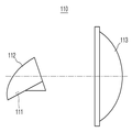
도 2는 도 1에 도시된 차량용 헤드 램프(110)의 내부 구조를 일례로 나타내는 구성도이다.2 is a block diagram showing an internal structure of the
도 2를 참조로, 차량용 헤드 램프(110)는 광원(111), 광원(111)의 광을 반사하는 리플렉터(112) 및 반사된 광을 굴절시켜 외부로 조사하는 렌즈(113)를 포함하되, 렌즈(113)의 광축을 기준으로 광원(111) 및 리플렉터(112)를 기울어지게 배치하여 렌즈(113)의 중심부로 리플렉터(112)로부터 반사된 광이 통과되게 하는 구성이다.2, the
광원(111)은 렌즈(113)의 광축을 기준으로 반 시계 방향의 미리 정해진 각도로 기울려져 배치된다. 광원(111)의 기울어진 각도는 광원(111)의 광이 리플렉터(112)의 반사면을 반사하여 렌즈(113)의 중심부로 대부분 향하게 각도로 설정되는 것이 바람직하다.The
여기서, 렌즈(113)의 중심부는 리플렉터(112)로부터 반사된 광이 렌즈(113)를 통과할 때, 색수차가 유발되는 렌즈(113)의 외측 영역을 제외한 렌즈(113) 영역을 일컫는 것으로서, 색수차가 발생되지 않는 렌즈(113)의 대부분 영역이 해당된다.The central portion of the
광원(111)의 기울어진 각도가 렌즈(113)의 광축에 대해 지나치게 기울어질 경우, 렌즈(113)의 광축으로부터 소폭 넓이의 협소한 영역에 리플렉터(112)로부터 반사된 광이 대부분 향하게 될 것이므로 차량 전방을 골고루 조명하기 위한 빔 패턴 형성할 수 없으므로 적절하지 않다.When the tilted angle of the
또한, 광원(111)의 기울어진 각도가 렌즈(113)의 광축에 대해 너무 낮은 기울기로 기울어질 경우, 리플렉터(112)로부터 반사된 광이 렌즈(113)에서 색수차가 유발되는 렌즈(113)의 외측 영역까지 향하는 경우가 빈번하기 때문에 적절하지 않다.When the tilted angle of the
따라서, 광원(111)의 기울어진 각도는 렌즈(113)에서 색수차가 유발되는 렌즈(113)의 외측 영역만을 제외하여 리플렉터(112)로부터 반사된 광이 향하도록 하는 레벨로 설정되는 것이 바람직하다.Therefore, it is preferable that the inclined angle of the
리플렉터(112)는 렌즈(113)의 광축을 기준으로 반 시계 방향의 미리 정해진 각도로 기울어져 배치된다. The
리플렉터(112)의 기울어진 각도는 광원(111)의 광이 리플렉터(112)의 반사면을 반사하여 렌즈(113)의 중심부로 대부분 향하게 하는 각도로 설정되는 것이 바람직하다.The inclined angle of the
리플렉터(112)의 기울어진 각도가 렌즈(113)의 광축에 대해 지나치게 기울어질 경우, 렌즈(113)의 광축으로부터 소폭 넓이의 협소한 영역에 리플렉터(112)로부터 반사된 광이 대부분 향하게 될 것이므로 차량 전방을 골고루 조명하기 위한 빔 패턴 형성을 할 수 없으므로 적절하지 않다.When the tilted angle of the
또한, 리플렉터(112)의 기울어진 각도가 렌즈(113)의 광축에 대해 너무 낮은 기울기로 기울어질 경우, 리플렉터(112)로부터 반사된 광이 렌즈(113)에서 색수차가 유발되는 렌즈(113)의 외측 영역까지 향하는 경우가 빈번하기 때문에 적절하지 않다.When the tilted angle of the
따라서, 리플렉터(112)의 기울어진 각도는 렌즈(113)에서 색수차가 유발되는 렌즈(113)의 외측 영역만을 제외하여 리플렉터(112)로부터 반사된 광이 향하도록 하는 레벨로 설정되는 것이 바람직하다.Therefore, it is preferable that the tilted angle of the
즉, 리플렉터(112)의 기울어진 각도는 광원(111)으로부터 발생된 광의 반사면 각도 조절과 관련된 것으므로, 광원(111)의 기울어진 각도와 밀접한 관련이 있다.That is, since the tilted angle of the
리플렉터(112)의 기울어진 각도와 광원(111)의 기울어진 각도를 상이하게 설정하여 광원(111)으로부터 발생된 광이 리플렉터(112)의 반사면에 반사되어 렌즈(113)의 중심부로 향하게 하거나, 리플렉터(112)의 기울어진 각도와 광원(111)의 기울어진 각도를 동일하게 설정하여 광원(111)으로부터 발생된 광이 리플렉터(112)의 반사면에 반사되어 렌즈(113)의 중심부로 향하게 하는 것이 가능하다.The inclined angle of the
이때, 리플렉터(112)의 기울어진 각도와 광원(111)의 기울어진 각도를 동일하게 설정하는 경우, 광원(111)으로부터 발생된 광이 리플렉터(112)의 반사면에 골고루 반사되어 렌즈(113)의 중심부로 향하는 것이 가능하여 광원(111)으로부터 발생된 광이 외부로 손실없이 조사되는 비율을 향상된다는 점에서, 바람직하다.In this case, when the inclined angle of the
또한, 리플렉터(112)의 기울어진 각도와 광원(111)의 기울어진 각도를 동일하게 설정하는 경우, 차량용 헤드 램프(110)의 조립 공정에서 리플렉터(112) 및 광원(111)이 장착되는 구조물에 리플렉터(112) 및 광원(111)을 장착한 이후 상기 구조물의 기울기 조절 또는 상기 구조물의 정해진 기울기 설정을 통해 보다 용이하게 본 발명의 차량용 헤드 램프(110)를 조립할 수 있다.When the inclined angle of the
도 3은 도 1에 도시된 차량용 헤드 램프(110)의 광원(111) 및 리플렉터(112) 배치를 일례로 나타내는 구성도이다.3 is a configuration diagram showing an example of the arrangement of the
도 3을 참조로, 차량용 헤드 램프(110) 내 광원(111)의 위치는 렌즈(113)의 광축과 광원(111)의 수직축 간에 직교하는 교차점이 리플렉터(112)의 외부에 형성되는 지점에 배치될 수 있다.3, the position of the
여기서, 리플렉터(112)의 외부에 교차점이 형성되는 지점이라 함은 리플렉터(112)의 반사면와 대응되는 곡면에 근접한 상측 위치를 일컫는다.Here, the point where the intersection is formed on the outside of the
리플렉터(112)의 외부에 교차점이 형성되는 지점은 광원(111) 및 리플렉터(112)의 기울기 레벨과 조합되는 파리미터로서, 렌즈(113)의 중심부, 렌즈(113)와 이격된 거리에 대응하여 광원(111) 및 리플렉터(112)의 기울기 레벨을 결정하는 데에 주요한 파라미터로 활용할 수 있다.The point where the intersection is formed outside the
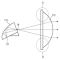
도 4는 도 3의 차량용 헤드 램프(110)를 통해 렌즈(113)의 중심부로 대부분의 광 레이가 집중되는 일례를 나타내는 예시도이다.4 is an exemplary view showing an example in which most of the light rays are concentrated at the center of the
도 4에 도시된 바와 같이, 렌즈(113)의 중심부는 색수차가 유발되는 렌즈(113)의 외측 영역인 A 및 B 영역이 제외된 영역이다. 광원(111) 및 리플렉터(112)의 기울어진 각도는 리플렉터(112)로부터 반사된 광이 렌즈(113)의 중심부로 향하는 비율과 대응될 수 있다.4, the central portion of the
또한, 렌즈(113)의 중심부, 렌즈(113)와 이격된 거리에 대응하여 광원(111) 및 리플렉터(112)의 기울기 레벨을 결정하기 위한 파리미터로서, 리플렉터(112)로부터 반사된 광이 모아지는 초점이 리플렉터(112)의 반사면으로 감싸진 내부 공간이 아니라 리플렉터(112)의 반사면으로 감싸진 내부 공간에서 벗어나서 렌즈(113)가 위치한 전방 방향으로 리플렉터(112)에 근접한 위치에 형성된다는 점을 활용할 수 있다.As a parameter for determining the tilt level of the
이때, 리플렉터(112)에 근접한 초점 위치가 리플렉터(112)의 끝단부로부터 떨어진 거리를 정확히 산출함으로써, 보다 정밀하게 광원(111) 및 리플렉터(112)의 기울기 레벨을 결정할 수도 있다.At this time, the tilt level of the
차량용 헤드 램프(110)의 조립 공정을 할 때, 렌즈(113)에 도달되는 광을 확인하지 않고서도 광원(111) 및 리플렉터(112)의 조립이 완료된 상태이면 광원(111)에 전원을 인가하여 초점이 형성되는 위치를 파악하는 것으로 광원(111) 및 리플렉터(112)의 기울기 레벨이 적절하게 이루어졌는지 대략적인 판단이 가능하게 할 수 있다.When assembling of the
도 5는 도 4의 렌즈(113) 영역을 더 구체적인 일례로 나타내는 구성도이다.5 is a diagram showing a
도 5에 도시된 바와 같이, 차량용 헤드 램프(110)의 렌즈(113)는 비구면 렌즈(113)로 구비될 수 있다.As shown in FIG. 5, the
도 5에 도시된 ① 영역은 전술한 렌즈(113)의 중심부이고, 도 5에 도시된 ② 영역은 전술한 렌즈(113)의 외측 영역이다. 이와 같이 ① 영역 및 ② 영역으로 구분되는 것은 비구면 렌즈(113)의 굴절률 차이를 기준으로 구분 가능하다.5 is a central portion of the
차량용 헤드 램프(110)에서, 광원(111)의 광은 하이 빔 패턴을 생성하기ㅣ 위한 것이거나 로우 빔 패턴을 생성하기 위한 것일 수 있다.In the
즉, 하이 빔 패턴으로 생성하기 위하여, 광원(111)의 광이 차량 전방의 외부로 조사될 경우, 광원(111)의 광이 리플렉터(112)로부터 반사되어 렌즈(113)의 ① 영역을 통과하여 차량 전방의 외부로 조사되는 것이 바람직하다. 리플렉터(112)로부터 반사된 광이 ② 영역을 통과하여 외부로 조사될 경우에는 빛이 분산되어 색수차가 발생되기 때문이다.That is, when the light of the
마찬가지로, 로우 빔 패턴을 생성하기 위하여, 광원(111)의 광이 차량 전방의 외부로 조사될 경우, 광원(111)의 광이 리플렉터(112)로부터 반사되어 렌즈(113)의 ① 영역을 통과하여 차량 전방의 외부로 조사되는 것이 바람직하다. 로우 빔 패턴일 때도 리플렉터(112)로부터 반사된 광이 ② 영역을 통과하여 외부로 조사될 경우에는 빛이 분산되어 색수차가 발생될 수 있는 바, 색수차 차단을 위해 리플렉터(112)로부터 반사된 광이 ② 영역을 통과하여 외부로 조사되는 것은 적절하지 않기 때문이다.Similarly, in order to generate a low beam pattern, when the light of the
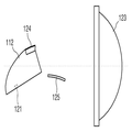
도 6은 도 1에 도시된 차량용 헤드 램프의 내부 구조를 다른 예로 나타내는 구성도이다.Fig. 6 is a configuration diagram showing another example of the internal structure of the vehicle headlamp shown in Fig. 1. Fig.
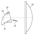
도 6을 참조로, 차량용 헤드 램프(120)는 광원(121), 광원(121)의 광을 반사하는 리플렉터(122), 반사된 광을 굴절시켜 외부로 조사하는 렌즈(123), 리플렉터(122)의 상측 전단부로부터 전방 하향으로 연장되는 제1 추가 반사판(124), 및 제1 추가 반사판(124)에 반사된 광을 수용하여 렌즈(123)의 중심부 중 상향 빔 발생 영역으로 통과되게 반사시키는 제2 추가 반사판(125)을 포함하는 구성이다.6, the vehicle headlamp 120 includes a
이때, 렌즈(123)의 광축을 기준으로 광원(121) 및 리플렉터(122)를 기울어지게 배치하여 렌즈(123)의 중심부로 리플렉터(122)로부터 반사된 광이 통과되도록 구성된다.At this time, the
광원(121)은 렌즈(123)의 광축을 기준으로 반 시계 방향의 미리 정해진 각도로 기울려져 배치된다. 광원(121)의 기울어진 각도는 광원(121)의 광이 리플렉터(122)의 반사면을 반사하여 렌즈(123)의 중심부로 대부분 향하게 각도로 설정되는 것이 바람직하다.The
여기서, 렌즈(123)의 중심부는 리플렉터(122)로부터 반사된 광이 렌즈(123)를 통과할 때, 색수차가 유발되는 렌즈(123)의 외측 영역을 제외한 렌즈(123) 영역을 일컫는 것으로서, 색수차가 발생되지 않는 렌즈(123)의 대부분 영역이 해당된다.The central portion of the
광원(121)의 기울어진 각도가 렌즈(123)의 광축에 대해 지나치게 기울어질 경우, 렌즈(123)의 광축으로부터 소폭 넓이의 협소한 영역에 리플렉터(122)로부터 반사된 광이 대부분 향하게 될 것이므로 차량 전방을 골고루 조명하기 위한 빔 패턴 형성할 수 없으므로 적절하지 않다.When the tilted angle of the
또한, 광원(121)의 기울어진 각도가 렌즈(123)의 광축에 대해 너무 낮은 기울기로 기울어질 경우, 리플렉터(122)로부터 반사된 광이 렌즈(123)에서 색수차가 유발되는 렌즈(123)의 외측 영역까지 향하는 경우가 빈번하기 때문에 적절하지 않다.When the tilted angle of the
따라서, 광원(121)의 기울어진 각도는 렌즈(123)에서 색수차가 유발되는 렌즈(123)의 외측 영역만을 제외하여 리플렉터(122)로부터 반사된 광이 향하도록 하는 레벨로 설정되는 것이 바람직하다.Therefore, it is preferable that the tilted angle of the
리플렉터(122)는 렌즈(123)의 광축을 기준으로 반 시계 방향의 미리 정해진 각도로 기울어져 배치된다. The
리플렉터(122)의 기울어진 각도는 광원(121)의 광이 리플렉터(122)의 반사면을 반사하여 렌즈(123)의 중심부로 대부분 향하게 하는 각도로 설정되는 것이 바람직하다.The inclined angle of the
리플렉터(122)의 기울어진 각도가 렌즈(123)의 광축에 대해 지나치게 기울어질 경우, 렌즈(123)의 광축으로부터 소폭 넓이의 협소한 영역에 리플렉터(122)로부터 반사된 광이 대부분 향하게 될 것이므로 차량 전방을 골고루 조명하기 위한 빔 패턴 형성을 할 수 없으므로 적절하지 않다.When the tilted angle of the
또한, 리플렉터(122)의 기울어진 각도가 렌즈(123)의 광축에 대해 너무 낮은 기울기로 기울어질 경우, 리플렉터(122)로부터 반사된 광이 렌즈(123)에서 색수차가 유발되는 렌즈(123)의 외측 영역까지 향하는 경우가 빈번하기 때문에 적절하지 않다.When the tilted angle of the
따라서, 리플렉터(122)의 기울어진 각도는 렌즈(123)에서 색수차가 유발되는 렌즈(123)의 외측 영역만을 제외하여 리플렉터(122)로부터 반사된 광이 향하도록 하는 레벨로 설정되는 것이 바람직하다.Therefore, it is preferable that the inclined angle of the
즉, 리플렉터(122)의 기울어진 각도는 광원(121)으로부터 발생된 광의 반사면 각도 조절과 관련된 것으므로, 광원(121)의 기울어진 각도와 밀접한 관련이 있다.That is, since the tilted angle of the
리플렉터(122)의 기울어진 각도와 광원(121)의 기울어진 각도를 상이하게 설정하여 광원(121)으로부터 발생된 광이 리플렉터(122)의 반사면에 반사되어 렌즈(123)의 중심부로 향하게 하거나, 리플렉터(122)의 기울어진 각도와 광원(121)의 기울어진 각도를 동일하게 설정하여 광원(121)으로부터 발생된 광이 리플렉터(122)의 반사면에 반사되어 렌즈(123)의 중심부로 향하게 하는 것이 가능하다.The inclined angle of the
이때, 리플렉터(122)의 기울어진 각도와 광원(121)의 기울어진 각도를 동일하게 설정하는 경우, 광원(121)으로부터 발생된 광이 리플렉터(122)의 반사면에 골고루 반사되어 렌즈(123)의 중심부로 향하는 것이 가능하여 광원(121)으로부터 발생된 광이 외부로 손실없이 조사되는 비율을 향상된다는 점에서, 바람직하다.In this case, when the inclined angle of the
또한, 리플렉터(122)의 기울어진 각도와 광원(121)의 기울어진 각도를 동일하게 설정하는 경우, 차량용 헤드 램프(120)의 조립 공정에서 리플렉터(122) 및 광원(121)이 장착되는 구조물에 리플렉터(122) 및 광원(121)을 장착한 이후 상기 구조물의 기울기 조절 또는 상기 구조물의 정해진 기울기 설정을 통해 보다 용이하게 본 발명의 차량용 헤드 램프(120)를 조립할 수 있다.When the inclined angle of the
제2 추가 반사판(125)은 리플렉터(122)의 반사판과 분리된 형상이며, 렌즈(123)의 광축을 기준으로 하방으로 경사져서 배치될 수 있다.The second
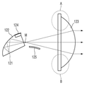
도 7은 도 6의 차량용 헤드 램프(120)를 통해 렌즈(123)의 중심부로 대부분의 광 레기가 집중되는 일례를 나타내는 예시도이다.FIG. 7 is an exemplary view showing an example in which most of the photoresists are concentrated at the center of the
도 7을 참조로, 렌즈(123)의 중심부는 색수차가 유발되는 렌즈(123)의 외측 영역인 C 및 D 영역이 제외된 영역이다. 광원(121) 및 리플렉터(122)의 기울어진 각도는 리플렉터(122)로부터 반사된 광이 렌즈(123)의 중심부로 향하는 비율과 대응될 수 있다.7, the center portion of the
또한, 렌즈(123)의 중심부, 렌즈(123)와 이격된 거리에 대응하여 광원(121) 및 리플렉터(122)의 기울기 레벨을 결정하기 위한 파리미터로서, 리플렉터(122)로부터 반사된 광이 모아지는 초점이 리플렉터(122)의 반사면으로 감싸진 내부 공간이 아니라 리플렉터(122)의 반사면으로 감싸진 내부 공간에서 벗어나서 렌즈(123)가 위치한 전방 방향으로 리플렉터(122)에 근접한 위치에 형성된다는 점을 활용할 수 있다.As a parameter for determining the tilt level of the
이때, 리플렉터(122)에 근접한 초점 위치가 리플렉터(122)의 끝단부로부터 떨어진 거리를 정확히 산출함으로써, 보다 정밀하게 광원(121) 및 리플렉터(122)의 기울기 레벨을 결정할 수도 있다.At this time, the tilt level of the
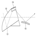
도 8은 도 6의 차량용 헤드 램프(120)를 통해 상향감 조정을 위한 반사 구조를 일례로 나타내는 구성도이다.FIG. 8 is a configuration diagram showing a reflective structure for adjusting the upward sense through the headlamp 120 for a vehicle shown in FIG.
도 8에 도시된 바와 같이, 제2 추가 반사판(125)은 리플렉터(122)의 반사판으로부터 반사된 광이 집중되는 초점 이후로 리플렉터(122)로부터 분리되어 배치될 수 있다.As shown in Fig. 8, the second
이와 같은 제2 추가 반사판(125)과 리플렉터(122)의 상측 전단부로부터 연장된 구조의 제1 추가 반사판(124)을 통해 차량 전방에 조사되는 광 패턴에 상향감을 더하는 것이 가능하다.It is possible to add an upward direction to the light pattern irradiated to the front of the vehicle through the second additional reflecting
도 8을 참조하면, 광원(121)의 광이 리플렉터(122)의 반사면에 반사된 총량은 대부분 렌즈(123)의 중심부에 골고루 통과된다. 즉, 광원(121)의 광이 리플렉터(122)의 반사면 중 어느 지점에 도달되어 반사되는지에 따라 렌즈(123)의 중심부 중 통과되는 광 레이가 상이해질 것이다.8, the total amount of the light from the
반면, 광원(121)의 광이 리플렉터(122)의 상측 전단부로부터 전방 하향으로 연장되는 제1 추가 반사판(124)에 도달되는 경우에는, 제1 추가 반사판(124)에 도달된 광은 제1 추가 반사판(124)으로부터 반사되어 미리 설계되어진 바에 따라 제2 추가 반사판(125)으로 향해진 후 제2 추가 반사판(125)으로부터 재차 반사된 광은 렌즈(123)의 중심부 중 상향 빔 발생 영역으로 통과된다. On the other hand, when the light from the
따라서, 차량용 헤드 램프(120)에 제1 추가 반사판(124) 및 제2 추가 반사판(125)이 더 포함되어 구성되는 경우는 차량 전방에 조사되는 광 패턴에 상향감을 더 하기 위한 목적으로 구성되는 것인 바, 광원(121)의 광이 하이 빔 패턴의 형성을 위한 것으로 한정될 필요가 있다. 물론, 차량용 헤드 램프(120)에 제1 추가 반사판(124) 및 제2 추가 반사판(125)이 더 포함되는 경우에도 광원(121)의 광이 로우 빔 패턴의 형성을 위한 것에도 적용되어 로우 빔 패턴의 상향감을 보완할 수 있다.Accordingly, in the case where the vehicle headlamp 120 further includes the first
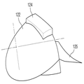
도 9는 도 6의 차량용 헤드 램프(120) 내부 구조를 입체적으로 나타내는 사시도이고, 도 10은 도 9에 도시된 램프 내부 구조의 측면도이며, 도 11은 도 9에 도시된 램프 내부 구조 중 광 반사 구성을 확대한 구성도이다.Fig. 9 is a perspective view showing the internal structure of the headlamp 120 for a vehicle in Fig. 6 in a stereoscopic manner, Fig. 10 is a side view of the lamp internal structure shown in Fig. 9, Fig.
도 9 내지 도 11에 도시된 바와 같이, 차량용 헤드 램프(120) 내 광원(121)의 위치는 렌즈(123)의 광축과 광원(121)의 수직축 간에 직교하는 교차점이 리플렉터(122)의 외부에 형성되는 지점에 배치될 수 있다.9 to 11, the position of the
리플렉터(122)의 반사판, 제1 추가 반사판(124) 및 제2 추가 반사판(125)은 미리 정해진 곡률로 구성되며, 각 반사판은 모두 상이한 곡률로 구비되거나, 리플렉터(122)의 반사판과 각 추가 반사판이 상이한 곡률로 구비될 수 있다.The
여기서, 리플렉터(122)의 반사판과 제1 추가 반사판(124)을 비교한다면, 제1 추가 반사판(124)은 리플렉터(122)의 반사판보다 상대적으로 작은 곡률로 구비될 수 있다.Here, if the reflector of the
제2 추가 반사판(125)이 곡면을 형성하는 구조로 된 것은 광의 반사를 위한 광학적 설계에 따른 것이나, 차량 전방에 조사되는 광 패턴 중 상향감을 보완하기 위해 추가되는 빔 패턴을 수평으로 퍼지는 패턴이 아니라 상향 일정 범위 내에 집중되는 빔 패턴 형성을 위한 것이다.The second additional reflecting
따라서, 제1 추가 반사판(124)으로부터 반사된 광의 광량이 한정적이라는 점을 감안해서, 한정적인 광량으로서 제1 추가 반사판(124)으로부터 반사된 광이 제2 추가 반사판(125)에 도달된다고 하더라도 제2 추가 반사판(125)의 곡률 구조를 통해 수용된 광을 모아 렌즈(123)의 중심부 중 상향 빔 발생 영역을 통과하도록 함에 따라, 차량 전방에 조사되는 광 패턴의 상향감을 더 향상시킬 수 있다.Therefore, even if the light reflected from the first
도 12는 도 11에 도시된 광 반사 구성의 측면도이다.12 is a side view of the light reflection structure shown in Fig.
도 12에 도시된 바와 같이 제2 추가 반사판(125)은 제1 추가 반사판(124)으로부터 반사된 광만을 수용할 수 있는 기울기로 기울어져 배치되는 것이 바람직하다.As shown in FIG. 12, the second
즉, 제2 추가 반사판(125)이 리플렉터(122)로부터 반사된 광을 수용하게 될 경우, 리플렉터(122)로부터 반사된 광을 반사시켜 굴절된 광은 렌즈(123)의 중심부가 아닌 렌즈(123)의 외측 영역에 도달되어 색수차를 유발할 수 있다. 따라서, 제2 추가 반사판(125)은 리플렉터(122)로부터 반사된 광은 도달되지 않도록 기울어져 배치되는 것이 바람직하다.That is, when the second
도 13은 도 9에 도시된 램프 내부 구조 중 광 반사 구성을 일체형 모듈로서 구비된 형상의 정면 사시도이고, 도 14는 도 13에 도시된 일체형 모듈 형상의 배면 사시도이다.FIG. 13 is a front perspective view of a light reflection structure of the lamp internal structure shown in FIG. 9 as an integrated module, and FIG. 14 is a rear perspective view of the integrated module shape shown in FIG.
도 13 및 도 14에 도시된 바와 같이, 리플렉터(122)의 반사면, 제1 추가 반사판(124) 및 제2 추가 반사판(125)이 일체형 모듈 형상으로서 구비될 수 있다. 이와 같이 일체형 모듈 형상으로 구비되어 차량용 헤드 램프(120)의 조립 공정을 진행할 때, 리플렉터(122), 제1 추가 반사판(124) 및 제2 추가 반사판(125)을 장착하는 효율을 높일 수 있다. As shown in Figs. 13 and 14, the reflecting surface of the
또한, 제1 추가 반사판(124) 및 제2 추가 반사판(125)의 기울기 설정 등이 미리 정해진 레벨에 맞도록 설정하여야 하는데, 개별 구성품으로서 조립할 경우 이러한 설정값에 맞게 조립을 실시하는 것이 용이하지 않으므로, 일체형 모듈 형상으로서 구비하는 것에 따른 이점이 있다.In addition, the inclination setting of the first
도 15는 도 13에 도시된 일체형 모듈 형상의 단면도이다.15 is a cross-sectional view of the integral module configuration shown in Fig.
도 15를 참조로, 리플렉터(122)의 반사면과 제1 추가 반사판(124)의 곡률이 상이하다는 것을 확인할 수 있으며, 제1 추가 반사판(124)의 곡률은 리플렉터(122)의 반사면에 대해 상대적으로 작은 곡률로 구비된다. 이를 통해, 제1 추가 반사판(124)으로 도달되는 광원(121)의 광을 더 퍼지게 하여 제2 추가 반사판(125)에 전달되도록 하는 역할을 하게 된다.15, it can be seen that the curvature of the first
도 16은 도 13 또는 도 14에 도시된 제1 추가 반사판의 형상을 더 구체적으로 나타내는 정면도이다.Fig. 16 is a front view showing the shape of the first additional reflector shown in Fig. 13 or Fig. 14 more specifically.
도 16에 도시된 바와 같이, 제1 추가 반사판(124)은 제1 추가 반사판(124)의 중심부로부터 좌우로 멀어질수록 리플렉터(122)의 반사면과의 단차가 커질 수 있다.As shown in FIG. 16, as the distance from the center of the first
즉, 제1 추가 반사판(124)은 리플렉터(122)의 반사면과 비교할 때, 도 15와 같이 측면 형상에서 확인되는 리플렉터 반사면과 상이한 곡률로 구비될 뿐만 아니라, 도 16과 같이 정면 형상에서 확인되는 리플렉터 반사면과도 상이한 곡률로 구비될 수 있다. 더군다나, 전술한 바와 같이 제1 추가 반사판(124)은 리플렉터(122)의 반사면에 대해 특정 단차를 갖는 형상으로 구비될 수 있다.That is, the first
도 17은 도 6의 차량용 헤드 램프(120)를 통해 상향감이 개선된 빔 패턴의 일례를 나타내는 예시도이고, 도 18은 도 17의 빔 패턴을 더 구체적인 그래픽으로 나타내는 예시도이다.FIG. 17 is an exemplary view showing an example of a beam pattern in which upward visibility is improved through the vehicle headlamp 120 of FIG. 6, and FIG. 18 is an exemplary diagram showing a beam pattern of FIG. 17 in more detail.
도 17 및 도 18에 도시된 바와 같이, 차량용 헤드 램프(120)를 통해 차량 전방에 조사하는 광 패턴이 기존 패턴(a)에서 본 발명 적용 패턴(b)으로 변경될 수 있다.17 and 18, the light pattern irradiated to the front of the vehicle through the vehicle headlamp 120 can be changed from the existing pattern a to the present invention application pattern b.
본 발명 적용 패턴(b)에서 확인되듯이, 하이 빔 패턴일 때 기존 패턴(a)에 비하여 명확하게 상향감이 보완된 것을 확인할 수 있다.As can be seen from the application pattern (b) of the present invention, it can be confirmed that the high-beam pattern is clearly enhanced as compared with the existing pattern (a).
이상과 첨부된 도면을 참조하여 본 발명의 실시 예를 설명하였지만, 본 발명이 속하는 기술분야에서 통상의 지식을 가진 자는 본 발명이 그 기술적 사상이나 필수적인 특징을 변경하지 않고서 다른 구체적인 형태로 실시될 수 있다는 것을 이해할 수 있을 것이다. 그러므로 이상에서 기술한 실시 예들은 모든 면에서 예시적인 것이며 한정적이 아닌 것으로 이해해야만 한다.While the present invention has been described in connection with what is presently considered to be practical exemplary embodiments, it is to be understood that the invention is not limited to the disclosed embodiments, but, on the contrary, It will be understood. It is therefore to be understood that the above-described embodiments are illustrative in all aspects and not restrictive.
또한, 본 발명은 차량용 헤드 램프에서 발생되는 색수차를 차단하면서 함께 차량 전방의 상향측 시야 확보를 더 개선할 수 있도록 전술한 광학 설계에 차량 전방의 상향감 개선용 광 패턴을 보완하는 추가 반사판 구성이 더 포함된 차량용 헤드 램프를 제공하기 위한 것임에 따라, 시판 또는 영업의 가능성이 충분할 뿐만 아니라 현실적으로 명백하게 실시할 수 있는 정도이므로 산업상 이용가능성이 있는 발명이다.Further, the present invention provides an additional reflector structure for supplementing the optical pattern for upward visibility improvement of the vehicle in the above-described optical design so as to further improve the securing of the upward visibility of the front of the vehicle while blocking the chromatic aberration generated in the vehicle headlamp The present invention is industrially applicable because it is intended to provide a headlamp for a vehicle including a vehicle headlamp which is more likely to be commercially available or operable and can be practically and practically carried out.
100, 110, 120: 차량용 헤드 램프
111, 121: 광원
112, 122: 리플렉터
113, 123: 렌즈
124: 제1 추가 반사판
125: 제2 추가 반사판100, 110, 120: head lamps for vehicles
111, 121: Light source
112, 122: Reflector
113, 123: lens
124: first additional reflector
125: second additional reflector
Claims (15)
상기 광원으로부터 출사된 광을 반사하는 리플렉터; 및
상기 반사된 광을 굴절시켜 외부로 조사하는 렌즈를 포함하되,
상기 반사된 광이 상기 렌즈의 중심부를 투과할 수 있도록, 상기 렌즈의 광축을 기준으로 상기 광원 및 상기 리플렉터가 상기 광이 투과되는 방향의 반대쪽 하방으로 기울어지게 배치되는 차량용 헤드 램프.Light source;
A reflector for reflecting the light emitted from the light source; And
And a lens for refracting and irradiating the reflected light to the outside,
Wherein the light source and the reflector are arranged to be inclined downwardly opposite to a direction in which the light is transmitted, with respect to an optical axis of the lens so that the reflected light can pass through the center portion of the lens.
상기 광원의 위치는 상기 렌즈의 광축과 상기 광원의 수직축 간에 직교하는 교차점이 상기 리플렉터의 외부에 형성되는 지점에 배치되는 차량용 헤드 램프.The method according to claim 1,
Wherein a position of the light source is disposed at a point where an intersection orthogonal to the optical axis of the lens and the vertical axis of the light source is formed outside the reflector.
상기 렌즈의 중심부는 상기 반사된 광이 상기 렌즈를 통과할 때, 색수차가 유발되는 상기 렌즈의 외측 영역을 제외한 렌즈 영역인 차량용 헤드 램프.The method according to claim 1,
Wherein a central portion of the lens is a lens region excluding an outer region of the lens where chromatic aberration is caused when the reflected light passes through the lens.
상기 광원 및 상기 리플렉터의 기울어진 각도는 상기 반사된 광이 상기 렌즈의 중심부로 향하는 비율과 대응되는 차량용 헤드 램프.The method according to claim 1,
Wherein the inclined angle of the light source and the reflector corresponds to the ratio of the reflected light to the center of the lens.
상기 광원으로부터 출사된 광은 하이 빔 패턴을 위한 것이거나, 로우 빔 패턴을 위한 것인 차량용 헤드 램프.The method according to claim 1,
Wherein the light emitted from the light source is for a high beam pattern or for a low beam pattern.
상기 리플렉터의 상측 전단부에 형성되는 제1 추가 반사판; 및
상기 제1 추가 반사판에 반사된 광을 수용하여 상기 렌즈의 중심부 중 상향 빔 발생 영역으로 통과되게 반사시키는 제2 추가 반사판을 더 포함하는 차량용 헤드 램프.The method according to claim 1,
A first additional reflection plate formed on an upper front end portion of the reflector; And
Further comprising a second additional reflector for receiving and reflecting the light reflected by the first additional reflector to pass through the upward beam generating area of the center of the lens.
상기 제2 추가 반사판은 상기 리플렉터의 반사판과 분리된 형상이며, 상기 렌즈의 광축을 기준으로 하방으로 경사져서 배치되는 차량용 헤드 램프.The method according to claim 6,
Wherein the second additional reflection plate is in a shape separated from a reflector of the reflector and is inclined downward with respect to an optical axis of the lens.
상기 제2 추가 반사판은 상기 리플렉터의 반사판으로부터 반사된 광이 집중되는 초점 이후로 분리 배치되는 차량용 헤드 램프.8. The method according to claim 6 or 7,
And the second additional reflection plate is separately disposed after the focal point in which the light reflected from the reflector of the reflector is concentrated.
상기 광원으로부터 출사된 광은 하이 빔 패턴을 위한 것인 차량용 헤드 램프.The method according to claim 6,
Wherein the light emitted from the light source is for a high beam pattern.
상기 리플렉터의 반사판, 상기 제1 추가 반사판 및 상기 제2 추가 반사판은 미리 정해진 곡률로 구비되는 차량용 헤드 램프.The method according to claim 6,
Wherein the reflector of the reflector, the first additional reflector, and the second additional reflector are provided with a predetermined curvature.
각 반사판은 모두 상이한 곡률로 구비되거나, 상기 리플렉터의 반사판과 각 추가 반사판이 상이한 곡률로 구비되는 차량용 헤드 램프.11. The method of claim 10,
Wherein each reflector is provided with a different curvature, or the reflector of the reflector and each additional reflector are provided with different curvatures.
상기 제1 추가 반사판은 상기 리플렉터의 반사판보다 작은 곡률로 구비되는 차량용 헤드 램프.12. The method of claim 11,
Wherein the first additional reflector is provided with a smaller curvature than the reflector of the reflector.
상기 제2 추가 반사판은 상기 제1 추가 반사판으로부터 반사된 광이 도달되는 기울기로 기울어져 배치되는 차량용 헤드 램프.The method according to claim 6,
And the second additional reflecting plate is inclinedly disposed at a slope at which light reflected from the first additional reflecting plate reaches.
상기 제2 추가 반사판은 상기 제1 추가 반사판보다 넓은 면적으로 구비되는 차량용 헤드 램프.The method according to claim 6,
Wherein the second additional reflector is provided in a larger area than the first additional reflector.
상기 제1 추가 반사판과 상기 리플렉터 반사판과의 단차는 상기 제1 추가 반사판의 중심부로부터 좌우로 멀어질수록 커지는 차량용 헤드 램프.The method according to claim 6,
Wherein the step difference between the first additional reflector and the reflector reflector increases as the distance from the center of the first additional reflector increases.
Priority Applications (1)
| Application Number | Priority Date | Filing Date | Title |
|---|---|---|---|
| KR1020150168878A KR20170062995A (en) | 2015-11-30 | 2015-11-30 | Vehicle head lamp |
Applications Claiming Priority (1)
| Application Number | Priority Date | Filing Date | Title |
|---|---|---|---|
| KR1020150168878A KR20170062995A (en) | 2015-11-30 | 2015-11-30 | Vehicle head lamp |
Publications (1)
| Publication Number | Publication Date |
|---|---|
| KR20170062995A true KR20170062995A (en) | 2017-06-08 |
Family
ID=59221358
Family Applications (1)
| Application Number | Title | Priority Date | Filing Date |
|---|---|---|---|
| KR1020150168878A Ceased KR20170062995A (en) | 2015-11-30 | 2015-11-30 | Vehicle head lamp |
Country Status (1)
| Country | Link |
|---|---|
| KR (1) | KR20170062995A (en) |
-
2015
- 2015-11-30 KR KR1020150168878A patent/KR20170062995A/en not_active Ceased
Similar Documents
| Publication | Publication Date | Title |
|---|---|---|
| JP6239265B2 (en) | Headlamps that output both low and high beams and have no moving parts | |
| US7178960B2 (en) | Vehicular illumination lamp | |
| JP6158549B2 (en) | Vehicle headlamp | |
| US20100309679A1 (en) | Vehicle headlight | |
| US9644810B2 (en) | Lamp unit | |
| JP6659456B2 (en) | Vehicle lighting | |
| KR102419832B1 (en) | Automotive Lighting Device | |
| JP2007179993A (en) | Vehicle headlamp | |
| KR102409832B1 (en) | Lamp for vehicle | |
| JP5713179B2 (en) | Projector headlamps for motorcycles | |
| KR102091488B1 (en) | lamp for vehicle | |
| KR101600564B1 (en) | Automotive lamp | |
| KR20150051672A (en) | Lamp for vehicle | |
| KR101461550B1 (en) | Lamp for vehicles | |
| KR20170070529A (en) | Lamp for vehicle | |
| KR20200058127A (en) | Lamp for vehicle | |
| KR20200058126A (en) | Lamp for vehicle | |
| KR20170062995A (en) | Vehicle head lamp | |
| KR20220132745A (en) | Automotive lamp | |
| KR101664036B1 (en) | Head light for vehicle | |
| KR101767990B1 (en) | A lamp for vehicles | |
| JP5023406B2 (en) | Vehicle headlamp unit | |
| JP5691514B2 (en) | Projector headlamps for motorcycles | |
| KR102924063B1 (en) | Lamp for vehicle | |
| KR20200034476A (en) | lamp for vehicle |
Legal Events
| Date | Code | Title | Description |
|---|---|---|---|
| A201 | Request for examination | ||
| PA0109 | Patent application |
Patent event code: PA01091R01D Comment text: Patent Application Patent event date: 20151130 |
|
| PA0201 | Request for examination | ||
| E902 | Notification of reason for refusal | ||
| PE0902 | Notice of grounds for rejection |
Comment text: Notification of reason for refusal Patent event date: 20161220 Patent event code: PE09021S01D |
|
| E601 | Decision to refuse application | ||
| PE0601 | Decision on rejection of patent |
Patent event date: 20170518 Comment text: Decision to Refuse Application Patent event code: PE06012S01D Patent event date: 20161220 Comment text: Notification of reason for refusal Patent event code: PE06011S01I |
|
| PG1501 | Laying open of application |