KR20170066638A - High-pressure connection device, high-pressure fuel pump, and method for producing a high-pressure connection device for a high-pressure fuel pump - Google Patents
High-pressure connection device, high-pressure fuel pump, and method for producing a high-pressure connection device for a high-pressure fuel pump Download PDFInfo
- Publication number
- KR20170066638A KR20170066638A KR1020177012801A KR20177012801A KR20170066638A KR 20170066638 A KR20170066638 A KR 20170066638A KR 1020177012801 A KR1020177012801 A KR 1020177012801A KR 20177012801 A KR20177012801 A KR 20177012801A KR 20170066638 A KR20170066638 A KR 20170066638A
- Authority
- KR
- South Korea
- Prior art keywords
- fuel
- pressure
- pretensioning
- fuel pump
- connecting device
- Prior art date
- Legal status (The legal status is an assumption and is not a legal conclusion. Google has not performed a legal analysis and makes no representation as to the accuracy of the status listed.)
- Granted
Links
Images






Classifications
-
- F—MECHANICAL ENGINEERING; LIGHTING; HEATING; WEAPONS; BLASTING
- F02—COMBUSTION ENGINES; HOT-GAS OR COMBUSTION-PRODUCT ENGINE PLANTS
- F02M—SUPPLYING COMBUSTION ENGINES IN GENERAL WITH COMBUSTIBLE MIXTURES OR CONSTITUENTS THEREOF
- F02M55/00—Fuel-injection apparatus characterised by their fuel conduits or their venting means; Arrangements of conduits between fuel tank and pump F02M37/00
- F02M55/004—Joints; Sealings
- F02M55/005—Joints; Sealings for high pressure conduits, e.g. connected to pump outlet or to injector inlet
-
- F—MECHANICAL ENGINEERING; LIGHTING; HEATING; WEAPONS; BLASTING
- F02—COMBUSTION ENGINES; HOT-GAS OR COMBUSTION-PRODUCT ENGINE PLANTS
- F02M—SUPPLYING COMBUSTION ENGINES IN GENERAL WITH COMBUSTIBLE MIXTURES OR CONSTITUENTS THEREOF
- F02M59/00—Pumps specially adapted for fuel-injection and not provided for in groups F02M39/00 -F02M57/00, e.g. rotary cylinder-block type of pumps
- F02M59/44—Details, components parts, or accessories not provided for in, or of interest apart from, the apparatus of groups F02M59/02 - F02M59/42; Pumps having transducers, e.g. to measure displacement of pump rack or piston
-
- F—MECHANICAL ENGINEERING; LIGHTING; HEATING; WEAPONS; BLASTING
- F02—COMBUSTION ENGINES; HOT-GAS OR COMBUSTION-PRODUCT ENGINE PLANTS
- F02M—SUPPLYING COMBUSTION ENGINES IN GENERAL WITH COMBUSTIBLE MIXTURES OR CONSTITUENTS THEREOF
- F02M2200/00—Details of fuel-injection apparatus, not otherwise provided for
- F02M2200/03—Fuel-injection apparatus having means for reducing or avoiding stress, e.g. the stress caused by mechanical force, by fluid pressure or by temperature variations
-
- F—MECHANICAL ENGINEERING; LIGHTING; HEATING; WEAPONS; BLASTING
- F02—COMBUSTION ENGINES; HOT-GAS OR COMBUSTION-PRODUCT ENGINE PLANTS
- F02M—SUPPLYING COMBUSTION ENGINES IN GENERAL WITH COMBUSTIBLE MIXTURES OR CONSTITUENTS THEREOF
- F02M2200/00—Details of fuel-injection apparatus, not otherwise provided for
- F02M2200/80—Fuel injection apparatus manufacture, repair or assembly
- F02M2200/8076—Fuel injection apparatus manufacture, repair or assembly involving threaded members
-
- F—MECHANICAL ENGINEERING; LIGHTING; HEATING; WEAPONS; BLASTING
- F02—COMBUSTION ENGINES; HOT-GAS OR COMBUSTION-PRODUCT ENGINE PLANTS
- F02M—SUPPLYING COMBUSTION ENGINES IN GENERAL WITH COMBUSTIBLE MIXTURES OR CONSTITUENTS THEREOF
- F02M2200/00—Details of fuel-injection apparatus, not otherwise provided for
- F02M2200/80—Fuel injection apparatus manufacture, repair or assembly
- F02M2200/8084—Fuel injection apparatus manufacture, repair or assembly involving welding or soldering
-
- F—MECHANICAL ENGINEERING; LIGHTING; HEATING; WEAPONS; BLASTING
- F02—COMBUSTION ENGINES; HOT-GAS OR COMBUSTION-PRODUCT ENGINE PLANTS
- F02M—SUPPLYING COMBUSTION ENGINES IN GENERAL WITH COMBUSTIBLE MIXTURES OR CONSTITUENTS THEREOF
- F02M39/00—Arrangements of fuel-injection apparatus with respect to engines; Pump drives adapted to such arrangements
- F02M39/02—Arrangements of fuel-injection apparatus to facilitate the driving of pumps; Arrangements of fuel-injection pumps; Pump drives
Landscapes
- Engineering & Computer Science (AREA)
- Chemical & Material Sciences (AREA)
- Combustion & Propulsion (AREA)
- Mechanical Engineering (AREA)
- General Engineering & Computer Science (AREA)
- Fuel-Injection Apparatus (AREA)
Abstract
본 발명은, 고압 연료 펌프(10)용 고압 연결 장치(50)로서, 다음 구성: - 상기 고압 연료 펌프(10)로부터 연료(14)를 배출하기 위한 출구 장치(18); - 상기 출구 장치(18)를 상기 출구 장치의 하류에 배열된 요소들에 연결하기 위한 연결 장치(22); - 상기 출구 장치(18)와 상기 연결 장치(22)를 연결하기 위한 용접 이음부(30); 및 - 상기 용접 이음부(30)에 상기 출구 장치(18)의 방향으로 프리텐셔닝(Fv)을 가하는 프리텐셔닝 장치(52)를 포함하는, 상기 고압 연결 장치(50)에 관한 것이다. 또한, 본 발명은 이러한 고압 연결 장치(50)를 구비하는 고압 연료 펌프(10) 및 이러한 고압 연결 장치(50)를 제조하는 방법에 관한 것이다.The present invention relates to a high pressure connection device (50) for a high pressure fuel pump (10) comprising: an outlet device (18) for discharging fuel (14) from the high pressure fuel pump (10); A connecting device (22) for connecting said outlet device (18) to elements arranged downstream of said outlet device; - a weld joint (30) for connecting said outlet device (18) and said connecting device (22); And a pretensioning device (52) for applying pre-tensioning (Fv) to the weld joint (30) in the direction of the outlet device (18). The present invention also relates to a high-pressure fuel pump (10) having such a high-pressure connecting device (50) and a method of manufacturing such a high-pressure connecting device (50).
Description
본 발명은 고압 연료 펌프를, 연료의 흐름 방향으로 고압 연료 펌프의 하류에 있는 연료 분사 시스템의 요소들에 연결할 수 있는 고압 연결 장치에 관한 것이다. 본 출원은 또한 이러한 고압 연결 장치를 제조하는 방법 및 이러한 고압 연결 장치를 구비하는 고압 연료 펌프에 관한 것이다.The present invention relates to a high pressure connection device capable of connecting a high pressure fuel pump to the elements of the fuel injection system downstream of the high pressure fuel pump in the direction of flow of the fuel. The present application also relates to a method for manufacturing such a high pressure connection device and to a high pressure fuel pump having such a high pressure connection device.
연료 분사 시스템은 일반적으로 예를 들어 디젤 또는 가솔린과 같은 연료를 내연 엔진의 연소 챔버로 분사하는데 사용된다. 연료 분사 시스템에서 연료는 가솔린이 연료로 사용될 때는 200 바(bar) 내지 300 바 범위의 고압으로 충전되고 디젤이 연료로 사용될 때는 2000 바 내지 3000 바 범위의 고압으로 충전(charged)된다. 본 명세서에서 압력으로 충전하는 것은 고압 연료 펌프에서 수행되는데, 이 고압 연료 펌프에서 펌프 피스톤은 병진 이동 방식으로 이동하며 상기 펌프 피스톤은 연료가 배치된 가압 챔버의 볼륨을 주기적으로 팽창시키고 감소시켜 연료에 고압을 발생시킨다. 이러한 방식으로 고압으로 충전된 연료는 이후에 고압 연료 펌프의 하류에 있는 연료 분사 시스템의 요소(element)들로 향하게 된다. 예를 들어, 내연 엔진의 연소 챔버로 연료를 분사하는 것은 종종 축압기, 즉 소위 레일(rail)에 의해 수행되는데, 이것이 대응하는 밸브에 의해 고압 연료 펌프로부터 연료를 초기에 레일에 도입하는 이유이다.Fuel injection systems are commonly used to inject fuel, such as, for example, diesel or gasoline, into the combustion chamber of an internal combustion engine. In the fuel injection system, the fuel is charged at a high pressure in the range of 200 bar to 300 bar when gasoline is used as fuel and at a high pressure in the range of 2000 bar to 3000 bar when the diesel is used as fuel. In this specification, filling with pressure is performed in a high-pressure fuel pump in which the pump piston moves in a translational manner and the pump piston periodically inflates and reduces the volume of the pressurized chamber in which the fuel is placed, High pressure is generated. The fuel charged in this manner at high pressure is then directed to the elements of the fuel injection system downstream of the high-pressure fuel pump. For example, injecting fuel into the combustion chamber of an internal combustion engine is often performed by an accumulator, or so-called rail, which is the reason for initially introducing fuel from the high-pressure fuel pump into the rail by the corresponding valve .
따라서, 연료의 흐름 방향으로 고압 연료 펌프의 하류에 있는 연료 분사 시스템의 요소들이 가압된 연료로 공급될 수 있도록 하기 위해, 고압 연료 펌프를 이들 하류 요소에 연결할 수 있는 연결 장치가 제공된다.Thus, in order to allow the elements of the fuel injection system downstream of the high-pressure fuel pump to be supplied to the pressurized fuel in the direction of flow of the fuel, a connecting device is provided which is capable of connecting the high-pressure fuel pump to these downstream elements.
고압 연료 펌프와 연결 장치를 연결하는 연결부는 연료에 나타나는 압력이 고압인 것으로 인해 그리고 이에 의해 힘이 발생하는 것으로 인해 기계적인 측면에서 높은 응력을 받는다. 연결부 또는 연결 장치의 구조 및 치수 레이아웃이 바람직하지 않은 경우에 이로 인해 각각 발생하는 맥동 인장 응력의 피크는 특히 연결 장치와 고압 연료 펌프 사이의 동적으로 응력을 받는 연결부를 파손시킬 수 있다. 그 결과, 이것은 연료의 누출 및 이와 관련된 안전 문제를 야기할 수 있어서, 유리하게는 회피되어야 한다.The connection between the high-pressure fuel pump and the connecting device is subjected to a high mechanical stress due to the high pressure in the fuel and the resulting force. If the structure and dimension layout of the connection or connection are undesirable, the peaks of the pulsating tensile stresses which respectively arise thereby can, in particular, break the dynamically stressed connection between the coupling device and the high-pressure fuel pump. As a result, this can lead to fuel leaks and associated safety problems, which should be advantageously avoided.
따라서, 본 발명의 목적은 작용하는 힘에 높은 저항력으로 대항할 수 있는 고압 연결 장치를 제안하는 것이다.It is therefore an object of the present invention to propose a high-pressure connection device capable of counteracting a high resistance to the acting force.
본 목적은 청구항 1의 특징을 갖는 고압 연결 장치에 의해 달성된다.This object is achieved by a high-pressure connecting device having the features of claim 1.
상기 고압 연결 장치를 갖는 고압 연료 펌프 및 이러한 고압 연결 장치를 제조하는 방법은 독립 청구항의 주제이다.The high pressure fuel pump with the high pressure connection device and the method of manufacturing such high pressure connection device are the subject of independent claims.
본 발명의 유리한 설계 실시예는 종속 청구항의 주제이다.Advantageous design embodiments of the present invention are subject of dependent claims.
고압 연료 펌프를, 연료의 흐름 방향으로 상기 고압 연료 펌프의 하류에 있는 연료 분사 시스템의 요소들에 연결하기 위한 고압 연결 장치는 상기 고압 연료 펌프 내에 압력으로 충전된 연료를 상기 고압 연료 펌프로부터 배출하는 출구 장치, 및 상기 출구 장치를 상기 연료의 흐름 방향으로 하류에 있는 상기 연료 분사 시스템의 요소들에 연결하기 위한 연결 장치를 포함한다. 상기 고압 연결 장치는 상기 출구 장치 및 상기 연결 장치를 고압 기밀(high-pressure-tight) 방식으로 연결하기 위한 용접 이음부(weld seam), 및 상기 용접 이음부에 상기 출구 장치의 방향으로 프리텐셔닝 힘(pretensioning force)을 가하기 위한 프리텐셔닝 장치를 더 포함한다.A high pressure connection device for connecting the high-pressure fuel pump to the elements of the fuel injection system downstream of the high-pressure fuel pump in the direction of flow of the fuel is configured to discharge fuel filled with pressure from the high- An outlet device, and a connecting device for connecting the outlet device to the elements of the fuel injection system downstream in the flow direction of the fuel. The high pressure connection device comprises a weld seam for connecting the outlet device and the connection device in a high-pressure-tight manner, and a pre- And a pretensioning device for applying a pretensioning force.
상기 출구 장치는 바람직하게는 상기 고압 연료 펌프의 하우징에 의해 형성되고, 상기 고압 연료 펌프의 환경을 상기 고압 연료 펌프의 가압 챔버에 연결하는 출구 구멍(outlet bore)을 구비한다.The outlet device is preferably formed by a housing of the high-pressure fuel pump and has an outlet bore that connects the environment of the high-pressure fuel pump to the pressure chamber of the high-pressure fuel pump.
상기 연료는 상기 고압 연료 펌프의 상기 가압 챔버로부터 상기 출구 구멍을 통해 상기 연결 장치로 흐르고 나서, 거기서부터 상기 연료 분사 시스템의 하류 측 요소들로 향하게 된다. 따라서, 상기 연료는 보통 상기 연결 장치의 길이방향 축과 평행하도록 배치된 흐름 방향으로 상기 출구 장치로부터 상기 연결 장치로 흐른다. 따라서, 상기 연결 장치의 길이방향 축과 상기 연료의 흐름 축은 통상 일치한다.The fuel flows from the pressurizing chamber of the high-pressure fuel pump through the outlet hole to the connecting device and from there to the downstream elements of the fuel injection system. Thus, the fuel usually flows from the outlet device to the connecting device in a flow direction arranged so as to be parallel to the longitudinal axis of the connecting device. Thus, the longitudinal axis of the connecting device and the flow axis of the fuel generally coincide.
따라서, 상기 출구 장치와 상기 연결 장치 사이를 단순히 연결하는 대신에, 상기 연결하는 용접 이음부에 프리텐셔닝 힘이 가해지고, 상기 프리텐셔닝 힘은 상기 용접 이음부에 작용하는 힘에 대항한다는 점에서 상기 고압 연결 장치에 안정된 연결이 제공된다. 여기서, 순수한 프리텐셔닝을 받는 연결부의 장점은 순수한 용접된 연결부의 장점과 결합되어 연결부를 안정화시키는 힘에 의해 훨씬 더 높은 압력에 대항할 수 있게 된다. 결국, 상기 고압 연료 펌프는 (가솔린 분야의 경우) 특히 300 바 내지 800 바 사이의 고압으로 연료를 충전하도록 구성된다. 디젤 분야에서는 훨씬 더 높은 최대 3000 바의 압력이 달성될 수 있다. 이러한 고압과 관련된 상기 고압 연결 장치는 순수한 나사 연결 또는 순수한 용접 연결만이 사용된 고압 연결 장치보다 훨씬 더 강력하다.Therefore, instead of simply connecting the outlet device and the connecting device, a pretensioning force is applied to the connecting welded joint, and the pretensioning force is opposed to the force acting on the welded joint A stable connection is provided to the high pressure connector. Here, the advantage of the connection subjected to pure pretensioning is to combine with the advantages of a purely welded connection, so that it can resist much higher pressure by the force of stabilizing the connection. As a result, the high-pressure fuel pump is configured to fill the fuel at high pressures (in the case of the gasoline field), especially between 300 bar and 800 bar. In the diesel field, a much higher pressure of up to 3000 bar can be achieved. The high pressure connection device associated with this high pressure is much more powerful than the high pressure connection device where only pure screw connection or pure welding connection is used.
따라서, 예를 들어, 레이저, 전자 빔, 커패시터 방전 또는 마찰 용접 등에 의한 용접 공정과, 용접 이음부를 포함하는 고압 연결부에 프리텐셔닝을 가하는 프리텐셔닝 장치의 결합이 선택된다. 이에 따라 용접 공정은 초기에 일어나고, 이후 전체 구조물이 보강(braced)된다. 이 때문에 힘과 응력이 용접 이음부로부터 고압 연결부 및 프리텐셔닝 장치의 덜 응력을 받는 영역을 걸쳐 주변 하우징으로 전달된다. 또한, 프리텐셔닝 힘과 적절한 설계 실시예를 결합하는 것에 의해 고압 연결 장치 그 자체의 응력을 또한 각각 설정하거나 제한할 수 있어서, 상기 고압 연결 장치 및 다른 모든 설치된 부품에서 동작의 무결성이 압력 요구조건이 더 증가된 경우에도 보장되게 유지된다.Thus, for example, a combination of a welding process with a laser, an electron beam, a capacitor discharge or friction welding, and a pretensioning device that applies pretensioning to a high-voltage connection including a welded joint is selected. Thus, the welding process occurs at an early stage, and then the entire structure is braced. For this reason, forces and stresses are transferred from the welded joint to the surrounding housing over the area under stress of the high tension connection and the pretensioning device. It is also possible to set or limit, respectively, the stresses of the high-pressure connector itself, by combining the pretensioning force with a suitable design embodiment so that the integrity of the operation in the high- Is maintained even if it is further increased.
비용 효과적인 용접된 연결은 유압적인-기계적인 요구조건이 더 증가하고 압력(가솔린의 경우 300 바 내지 800 바 범위, 및 디젤의 경우 1500 바 내지 3000 바 범위)이 증가하는 경우에도 이 새로운 솔루션을 통해 각각 구현되거나 유지될 수 있다. 이 경우 추가적인 프리텐셔닝 장치와 필요한 장치 공간만이 추가적으로 요구된다. 따라서, 보다 낮은 압력 레벨의 맥락에서 알려진 구성 요소(component)들이 약간 변형하면 더 사용될 수 있다. 추가적으로 용접 이음부에 추가적인 응력을 야기하지 않으면서 고압 연결부의 벽 두께를 두껍게 할 수 있어서, 이에 의해 외부 파이프 장치를 연결 장치 상에 또는 연결 장치에 각각 조이거나 고정시킬 때 전단력과 관련하여 안전성이 향상되는 장점을 제공한다.Cost-effective welded joints also increase the hydraulic-mechanical requirements and increase the pressure (ranging from 300 bar to 800 bar for gasoline and from 1500 bar to 3000 bar for diesel) Respectively. In this case, additional pretensioning devices and necessary equipment space are additionally required. Thus, known components in the context of a lower pressure level may be used further if slightly modified. In addition, the wall thickness of the high-pressure connections can be made thicker without causing additional stresses on the weld joints, thereby enhancing safety with respect to shear forces when the external pipe device is tightened or fastened to the connecting device or to the connecting device, respectively Provides advantages.
고압 연결 장치의 압력 상한은 재료 탄성, 수명에 걸쳐 최대 달성 가능한 프리텐셔닝 힘(FV) 및 연결 장치의 직경을 조합하여 유도된다. 특히, 나사산과-관련된 손실 등에 의해 최대 달성 가능한 프리텐셔닝 힘(FV)은 직경이 증가함에 따라 점점 더 작아지므로, 작은 직경을 사용하는 것이 최적이 된다. 직경이 작으면 축방향 힘이 작아짐과 함께 달성 가능한 프리텐셔닝 힘(FV)이 높아진다.The upper pressure limit of the high pressure connector is derived by combining material elasticity, the maximum attainable pretensioning force (F V ) over the lifetime and the diameter of the connecting device. In particular, the maximum achievable pretensioning force (F V ) due to thread-related losses or the like becomes smaller as the diameter increases, so that it is optimal to use a smaller diameter. If the diameter is smaller axial force is the higher the pretensioning force (F V) is achievable with smaller.
유리하게는, 압력 경감 밸브의 밸브 개구가 상기 연결 장치에서 연료 입구 볼륨으로 개방되는 방식으로 상기 압력 경감 밸브(pressure-relief valve)가 상기 출구 장치에 배치되고, 상기 연료 입구 볼륨은 상기 연료가 상기 출구 장치로부터 상기 연결 장치로 흐르는 것을 허용하도록 구성된다.Advantageously, the pressure relief valve is arranged in the outlet device in such a way that the valve opening of the pressure relief valve opens from the connecting device to the fuel inlet volume, To flow from the outlet device to the connecting device.
압력 경감 밸브는 상기 고압 연료 펌프의 하류에 있는 요소들을 보호하는 데 유리한다. 상기 압력 경감 밸브의 상기 밸브 개구가 상기 연결 장치의 상기 연료 입구 볼륨으로 개방될 수 있도록 하기 위해, 충분한 장치 공간이 제공되는 것이 유리하며, 이에 의해 이러한 압력 경감 밸브가 없는 배열에 비해 상기 연결 장치의 직경이 현저하게 확대된다. 이렇게 직경이 더 커지면 상기 출구 장치와 상기 연결 장치 사이의 접촉면이 더 커지는 것으로 인해 접촉 압력이 감소되기 때문에 이렇게 직경이 더 커지면 상기 출구 장치와 상기 연결 장치 사이의 연결부에 부정적인 영향을 줄 수 있다.The pressure relief valve is advantageous for protecting the elements downstream of the high-pressure fuel pump. It is advantageous that a sufficient device space is provided so that the valve opening of the pressure relief valve can be opened to the fuel inlet volume of the connecting device, The diameter is remarkably enlarged. This larger diameter may have a negative effect on the connection between the outlet device and the connecting device if the diameter is so increased because the contact pressure is reduced due to the greater contact surface between the outlet device and the connecting device.
직경이 더 커지면 현재까지 사용된 순수한 프리텐셔닝 연결뿐만 아니라 순수한 용접된 연결에 부정적인 영향을 미친다.Larger diameters have a negative impact on purely welded connections as well as pure pretensioning connections used to date.
순수한 프리텐셔닝 연결의 경우, 가장 자주 내부 물림 에지(biting edge)가 밀봉을 위해 제공되고, 연질-메탈 디스크가 공차를 균등하게 하기 위해 제공된다. 이 물림 에지의 직경은 이제 상기 압력 경감 밸브를 위한 장치 공간에 필요한 직경이 더 커지는 것으로 인해 증가된다. 따라서, 보강된 부품들 사이의 접촉 압력이 면이 더 커지는 것으로 인해 떨어진다. 그러나, 추가적으로, 가능한 최대 축방향 프리텐셔닝 힘(FV)이 또한 나사산의 마찰 손실이 더 커지는 것에 의해 떨어지게 된다.In the case of a pure pretensioning connection, the biting edge is most often provided for sealing, and a soft-metal disk is provided for equalizing the tolerances. The diameter of this biting edge is now increased due to the larger diameter required for the device space for the pressure relief valve. Thus, the contact pressure between the reinforced parts drops due to the larger surface area. However, additionally, the maximum possible axial pretensioning force (F V ) also falls due to the greater friction loss of the threads.
직경이 증가될 때, 진원(roundness)으로부터 가능한 편차 및 물린 에지의 직교성으로부터 편차는, 물림 에지가 중심으로부터 상당히 더 멀리 떨어지도록 위치되므로 각각 추가적으로 상당히 더 큰 영향을 미친다. 기본적으로 물림 에지에 의해 공차를 균등하게 하도록 의도된 연질-금속 디스크는 소성 변형에 의해 공차 편차를 균등하게 할 수 있도록 충분히 높은 프리텐셔닝 힘(FV)이 가해져야 한다. 그러나, 이 프리텐셔닝 힘(FV)은 전술한 이유로 인해 떨어지고, 이제 더 큰 면으로 전달되어야 한다.When the diameter is increased, the deviation from the roundness and the deviation from the orthogonality of the biting edge are each additionally considerably greater, since the biting edge is located farther away from the center. Basically, a soft-metal disk intended to equalize the tolerances by the engaging edges should be subjected to a pretensioning force (F V ) sufficiently high to allow the tolerance deviations to be equalized by plastic deformation. However, this pretensioning force F V has dropped for the reasons stated above and is now to be transmitted to the larger surface.
융합된 구역(fused zone)의 크기에 의해 용접된 연결부는 기밀성(tightness)을 잃지 않고 상당히 더 큰 공차를 균등하게 할 수 있다. 여기서, 특히, 자주 사용되는 마이크로 용접 이음부의 좁은 링크 길이는 압력 레벨 면에서 제한적인 효과를 가지고, 이에 의해 용접 이음부로부터 연결 장치 및 주변 하우징으로 응력을 안내하는 구조를 야기한다. 이에 따라 연결 장치의 달성 가능한 두께가 떨어지고, 압력이 상승하는 경우 재료에 과도하게 응력이 가해지는 지점에 도달하게 된다.The joint welded by the size of the fused zone can equalize the significantly larger tolerances without losing the tightness. Here, in particular, the narrow link length of frequently used micro weld joints has a limited effect in terms of pressure level, thereby causing a structure to guide the stress from the welded joint to the connecting device and the peripheral housing. This results in a decrease in the achievable thickness of the connecting device and reaches a point where excessive stress is applied to the material when the pressure rises.
프리텐셔닝 연결부 및 용접된 연결부의 장점들이 고압 연결 장치에서 통합되면, 압력 경감 밸브에 의해 연결 장치의 연료 입구 볼륨의 직경이 비교적 큰 경우 예를 들어 300 바 내지 800 바 범위 또는 그 이상의 높은 압력 레벨을 달성할 수 있다. 추가적인 장점은 이미 알려져 있고 매우 잘 관리된 가공 및 용접 공정을 갖는 이미 이용가능한 조립 라인을 계속 사용할 수 있다는 점에 있다.When the advantages of the pre-tensioning connection and the welded connection are integrated in the high-pressure connection, the pressure relief valve allows the fuel inlet volume of the connection to be relatively large, for example, in the range of 300 bar to 800 bar or higher, Can be achieved. An additional advantage lies in the ability to continue to use already known assembly lines with well-known machining and welding processes.
상기 프리텐셔닝 장치는 바람직하게는 상기 출구 장치를 향하는 프리텐셔닝 면을 구비하고, 상기 프리텐셔닝 면은 상기 용접 이음부에 프리텐셔닝을 가하기 위해 상기 연결 장치의 접촉면에서 지지된다. 따라서, 상기 프리텐셔닝 힘은 상기 연결 장치 그 자체에 의해 상기 용접 이음부에 유리하게 인가될 수 있다.The pretensioning device preferably has a pretensioning surface facing the outlet device and the pretensioning surface is supported at the contact surface of the connecting device to apply pretensioning to the welded joint. Thus, the pretensioning force can be advantageously applied to the welded joint by the connecting device itself.
하나의 유리한 설계 실시예에서, 상기 프리텐셔닝 면과 상기 접촉면의 접촉 영역은 상기 연료의 흐름 방향으로 상기 용접 이음부 위에 실질적으로 수직으로 있도록 배치된다. 이로 인해, 상기 용접 이음부의 임의의 리프팅 또는 파열이 효과적으로 상쇄되고 이에 요구되는 프리텐셔닝 힘이 감소되기 때문에 바람직하게는 가능한 한 효율적으로 상기 용접 이음부에서 응력이 해제(destressed)될 수 있다.In one advantageous design embodiment, the contact area of the pretensioning surface and the contact surface is arranged to be substantially perpendicular to the weld seam in the direction of flow of the fuel. This allows the stresses in the welded joint to be destressed, preferably as efficiently as possible, since any lifting or rupture of the welded joint is effectively canceled and the required pretensioning force is reduced.
상기 연결 장치 상의 접촉면은 바람직하게는 상기 프리텐셔닝 힘이 상기 연결 장치의 원주를 통해 상기 용접 이음부에 걸쳐 균일하게 가해지도록 둘러싸도록 제공된다.The contact surface on the connecting device is preferably provided so as to surround the pre-tensioning force uniformly across the welded joint through the circumference of the connecting device.
하나의 추가적인 바람직한 설계 실시예에서, 연료의 흐름 방향으로 접촉 영역은 흐름 방향에 실질적으로 수직이도록 배치되어, 상기 프리텐셔닝 힘이 바람직하게는 정밀하게 흐름 연료에 의해 작용하는 힘들에 대항할 수 있다.In one additional preferred design embodiment, the contact area in the direction of flow of the fuel is arranged to be substantially perpendicular to the flow direction so that the pretensioning force can preferably counteract forces acting by the flow fuel precisely .
그러나, 대안적인 설계 실시예에서, 접촉 영역은 또한 흐름 방향에 대해 각도(α), 특히 30° < α < 80°, 특히 α = 45° 각도로 배치될 수 있다. 이것은 더 작은 외부 직경을 갖는 연결 장치를 사용할 수 있다는 장점을 제공한다. 상기 프리텐셔닝 장치는 바람직하게는 상기 프리텐셔닝 장치가 최소 내부 직경을 가지도록 각 배열로 조립되도록 상기 프리텐셔닝 장치가 상기 연결 장치 위로 당겨지도록 구성된다. 상기 용접 이음부가 배치된 영역에서 상기 연결 장치가 작은 외부 직경을 갖는 경우 상기 접촉면과 상기 프리텐셔닝 면의 접촉 영역은 잠재적으로 더 이상 수립될 수 없다. 그러나, 각진 접촉 구역에 의해, 프리텐셔닝 힘이 상기 용접 이음부에 가해질 수는 있다.However, in an alternative design embodiment, the contact area may also be arranged at an angle?, In particular 30 ° <α <80 °, in particular α = 45 °, with respect to the flow direction. This provides the advantage that a connection device with a smaller outer diameter can be used. The pretensioning device is preferably configured such that the pretensioning device is pulled over the connecting device such that the pretensioning device is assembled into each array with a minimum inner diameter. If the connecting device has a small outer diameter in the region where the welded joint is located, the contact area of the contact surface and the pretensioning surface can not be potentially established anymore. However, the pre-tensioning force can be applied to the welded joint by the angled contact zone.
리세스(recess)가 바람직하게는 상기 출구 장치 상에 구성되고, 상기 프리텐셔닝 장치는 상기 리세스에 맞물리도록 구성된다. 이에 의해, 상기 프리텐셔닝 장치는 유리하게는 상기 출구 장치로 힘을 소산(dissipate)시킬 수 있다. 상기 출구 장치 상의 리세스는 바람직하게는 둘러싸이도록 배치되고, 상기 프리텐셔닝 장치는 상기 프리텐셔닝 장치의 원주 상에 또한 배치된 둘러싸는 벽을 구비하고, 상기 벽은 상기 리세스에 맞물린다. 이에 따라 상기 리세스와 상기 프리텐셔닝 장치 사이에 특히 신뢰성 있는 접촉이 보장된다.A recess is preferably configured on the outlet device, and the pretensioning device is configured to engage the recess. Thereby, the pretensioning device can advantageously dissipate the force to the outlet device. The recess on the outlet device is preferably arranged to be enclosed and the pretensioning device has an enclosing wall which is also arranged on the circumference of the pretensioning device and the wall is engaged with the recess. Thereby ensuring particularly reliable contact between the recess and the pretensioning device.
특히 유리하게는, 상기 리세스는 외부 리세스 나사산을 갖고, 상기 프리텐셔닝 장치는 상기 외부 리세스 나사산과 맞물리기 위한 내부 프리텐셔닝 장치 나사산을 구비한다. 이 때문에, 상기 프리텐셔닝 장치를 상기 리세스에 나사 결합시킴으로써 상기 프리텐셔닝 힘이 상기 용접 이음부 상에 특히 균일하고 견고히 유리하게 인가될 수 있다.Advantageously, said recess has an external recess thread, said pretensioning device having an internal pretensioning device thread for engaging said external recess thread. For this reason, by screwing the pretensioning device into the recess, the pretensioning force can be particularly advantageously applied uniformly and firmly on the welded joint.
상기 프리텐셔닝 장치는 예를 들어 너트로 형성된다. 그러나, 대안적으로 상기 프리텐셔닝 장치는 또한 플랜지-나사 조립체에 의해 형성될 수 있다. 너트로 구성되면 프리텐셔닝 힘이 상기 연결 장치의 전체 원주를 통해 상기 용접 이음부에 균일하게 가해질 수 있다는 장점을 제공한다. 플랜지-나사 조립체는 너트를 갖는 배열의 경우에서보다 더 많은 자유도와 더 많은 공간을 이용가능할 수 있다는 장점을 제공한다. 예를 들어, 플랜지-나사 조립체는 상기 출구 장치의 대응하는 구멍과 상호 작용하는 적어도 2개의 나사를 구비한다.The pretensioning device is formed of, for example, a nut. However, alternatively, the pretensioning device may also be formed by a flange-screw assembly. Nut provides the advantage that a pre-tensioning force can be applied uniformly to the welded joint through the entire circumference of the connecting device. The flange-screw assembly offers the advantage that more freedom and more space may be available than in the case of an arrangement with a nut. For example, the flange-screw assembly has at least two screws interacting with corresponding apertures in the outlet device.
특히 실질적으로 원형이도록 구성된 그루브(groove)가 상기 출구 장치에 유리하게 배치된다. 하나의 바람직한 실시예에서 상기 용접 이음부는 상기 그루브에 배치되고, 따라서 유리하게는 상기 출구 장치에 안착하도록 제공된다. 그러나, 대안적인 설계 실시예에서 상기 용접 이음부는 또한, 상기 연료의 흐름 축에 수직이도록, 즉 상기 연결 장치의 길이방향 축을 향하도록, 상기 그루브 옆에서 상기 연료의 흐름 축을 향하는 방향으로 배치될 수 있다. 상기 그루브는 상기 용접 이음부 옆에 배치될 때 유리하게는 상기 용접 이음부에 작용하는 힘을 소산시켜 상기 용접 이음부에서 응력을 해제할 수 있다.In particular, a groove configured to be substantially circular is advantageously disposed in the outlet device. In one preferred embodiment the welded joint is arranged in the groove and is therefore advantageously provided to seat on the outlet device. However, in an alternative design embodiment the welded joint can also be arranged in a direction perpendicular to the flow axis of the fuel, i.e. towards the longitudinal axis of the connecting device, towards the flow axis of the fuel next to the groove . The groove can advantageously dissipate the forces acting on the weld seam when it is placed next to the weld seam to release the stress in the weld seam.
상기 연결 장치의 돌출 영역은 상기 출구 장치와 접촉하는 상기 연결 장치의 제1 단부 상에 배치되는 것이 바람직하고, 여기서 상기 돌출 영역은 상기 용접 이음부가 배치되는 용접면을 갖는다. 상기 돌출 영역을 통해, 상기 프리텐셔닝 장치에 의해 상기 용접 이음부에 힘을 가할 수 있는 면이 유리하게 이용가능하다. 본 명세서에서, 상기 연결 장치가 상기 돌출 영역에서 상기 프리텐셔닝 장치와 접촉하는 접촉면은 바람직하게는 상기 용접 이음부가 위치되는 용접면과 반대쪽에 있도록 배치된다. 따라서, 상기 돌출 영역은 상기 프리텐셔닝 장치로부터 프리텐셔닝 힘을 상기 반대쪽 용접 이음부로 전달한다.The protruding region of the connecting device is preferably disposed on the first end of the connecting device in contact with the outlet device, wherein the protruding region has a welding surface on which the welded joint is disposed. Through this projecting area, a surface which can apply force to the welded joint by the pretensioning device is advantageously usable. In this specification, the contact surface at which the connecting device makes contact with the pretensioning device in the projecting area is preferably arranged so as to be opposite to the welding surface on which the welded joint is located. Thus, the protruding region transfers the pretensioning force from the pretensioning device to the opposite welded joint.
바람직한 설계 실시예에서, 상기 연결 장치를, 상기 연료의 흐름 방향으로 하류에 있는 상기 연료 분사 시스템의 요소들에 연결하기 위한 상기 연결 장치의 연결 영역은 상기 제1 단부의 반대쪽 상기 연결 장치의 제2 단부에 배치된다. 본 명세서에서 상기 제2 단부에서 상기 연결 장치는 유리하게는 상기 연결 장치의 하류에 있는 요소들을 유리하게는 상기 연결 장치에 쉽게 고정시킬 수 있는 외부 나사산을 구비한다. 상기 제1 단부에서 상기 연결 장치의 외부 직경은 바람직하게는 상기 제2 단부에서의 것보다 더 크다. 바람직하게는 상기 프리텐셔닝 장치의 최소 내부 직경은 상기 제2 단부의 외부 직경보다 더 크고, 상기 제1 단부의 외부 직경보다 더 작아서, 한편으로는 상기 프리텐셔닝 장치를 상기 연결 장치 위로 단순히 당길 수 있고, 다른 한편으로는 상기 연결 장치의 돌출 영역과 신뢰성 있는 접촉을 수립할 수 있다.In a preferred design embodiment, the connecting area of the connecting device for connecting the connecting device to the elements of the fuel injection system downstream in the flow direction of the fuel is connected to the second part of the connecting device on the opposite side of the first end, Respectively. Here, at the second end, the connecting device advantageously has an external thread which can advantageously fasten the elements downstream of the connecting device to the connecting device. The outer diameter of the connecting device at the first end is preferably larger than that at the second end. Preferably the minimum inner diameter of the pretensioning device is greater than the outer diameter of the second end and is smaller than the outer diameter of the first end so that the pretensioning device is simply pulled over the connecting device And on the other hand, establish reliable contact with the protruding region of the connecting device.
고압으로 연료를 충전하는 고압 연료 펌프는 전술한 고압 연결 장치를 구비한다.The high-pressure fuel pump for filling the fuel with high pressure is equipped with the above-described high-pressure connecting device.
고압 연료 펌프를 위한 고압 연결 장치를 제조하는 방법에서, 다음 단계들:In a method of manufacturing a high-pressure connector for a high-pressure fuel pump, the following steps:
- 상기 고압 연료 펌프로부터 연료를 배출하기 위한 출구 장치를 제공하는 단계;- providing an outlet device for discharging fuel from the high pressure fuel pump;
- 상기 출구 장치를, 상기 연료의 흐름 방향으로 하류에 있는 연료 분사 시스템의 요소들에 연결하기 위한 연결 장치를 제공하는 단계;- providing a connecting device for connecting said outlet device to the elements of the fuel injection system downstream in the flow direction of said fuel;
- 상기 출구 장치와 상기 연결 장치를 연결하기 위한 용접 이음부를 생성하는 단계; 및- creating a welded joint for connecting said outlet device and said connecting device; And
- 상기 출구 장치의 방향으로 프리텐셔닝 힘이 상기 용접 이음부에 작용하는 방식으로 프리텐셔닝 장치를 상기 연결 장치에 배치하는 단계가 수행된다.- placing the pretensioning device in the connecting device in such a manner that a pretensioning force acts on the welded joint in the direction of the outlet device.
본 명세서에서 상기 용접 이음부는, 예를 들어, (전자빔 또는 레이저 빔에 의해) 외부로부터 빔 용접 또는 내부 용접 방법으로서 커패시터 방전 용접 또는 마찰 용접 방법과 같은 여러 용접 방법에 의해 각각 생성될 수 있다.Herein, the weld joint can be produced by various welding methods such as, for example, an external beam welding (by an electron beam or a laser beam) or a capacitor discharge welding or friction welding method as an internal welding method.
상기 프리텐셔닝 장치로부터 상기 용접 이음부로 프리텐셔닝 힘을 확실히 전달하는 것을 보장할 수 있도록 하기 위해, 상기 연결 장치에 상기 프리텐셔닝 장치를 배치하기 전에 상기 용접 이음부가 응고되도록 놓아 두는 것이 바람직하다.In order to ensure that the pretensioning force is reliably transmitted from the pretensioning device to the welded joint, it is preferred that the welded joint is allowed to coagulate prior to placing the pretensioning device on the connecting device .
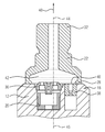
본 발명의 유리한 설계 실시예가 첨부 도면에 의해 아래에서 보다 상세히 설명된다.Advantageous design embodiments of the present invention are described in more detail below with reference to the accompanying drawings.
도 1은 고압 연료 펌프에서 압력으로 충전되는 연료를 배출하기 위한 출구 장치를 갖는 고압 연료 펌프의 사시도;
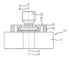
도 2는 출구 장치 상에 배치된 연결 장치를 구비하는 도 1의 고압 연료 펌프의 상세 사시도;
도 3은 도 2의 연결 장치를 갖는 고압 연료 펌프의 단면도;
도 4는 연결 장치, 출구 밸브 및 압력 경감 밸브를 갖는 고압 연료 펌프의 다른 단면도;
도 5는 제1 실시예에 따라 도 1에 도시된 고압 연료 펌프 상에 있는 고압 연결 장치의 단면도;
도 6은 도 5에 따른 고압 연결 장치의 개별 영역에서 응력 분포의 개략도;
도 7은 제2 실시예에 따라 도 1에 도시된 고압 연료 펌프 상에 있는 고압 연결 장치의 단면도;
도 8은 도 7에 따른 고압 연결 장치의 개별 영역에서 응력 분포의 개략도;
도 9는 제3 실시예에 따라 도 1에 도시된 고압 연료 펌프 상에 있는 고압 연결 장치의 단면도;
도 10은 도 9에 따른 고압 연결 장치의 개별 영역에서 응력 분포의 개략도;
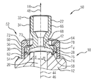
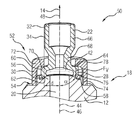
도 11은 제4 실시예에 따라 도 1에 따른 고압 연료 펌프 상에 있는 고압 연결 장치의 사시도; 및
도 12는 도 11의 고압 연결 장치의 다른 사시도.1 is a perspective view of a high-pressure fuel pump having an outlet device for discharging fuel to be filled with pressure in a high-pressure fuel pump;
Figure 2 is a detailed perspective view of the high-pressure fuel pump of Figure 1 with a connecting device disposed on the outlet device;
3 is a cross-sectional view of a high-pressure fuel pump with the coupling device of FIG. 2;
4 is another cross-sectional view of a high pressure fuel pump having a connecting device, an outlet valve and a pressure relief valve;
5 is a sectional view of the high pressure connection device on the high-pressure fuel pump shown in Fig. 1 according to the first embodiment; Fig.
Figure 6 is a schematic view of the stress distribution in the individual regions of the high pressure connector according to Figure 5;
7 is a cross-sectional view of the high pressure connection device on the high-pressure fuel pump shown in Fig. 1 according to the second embodiment; Fig.
Figure 8 is a schematic view of the stress distribution in the individual regions of the high pressure connector according to Figure 7;
9 is a cross-sectional view of the high pressure connection device on the high-pressure fuel pump shown in Fig. 1 according to the third embodiment; Fig.
10 is a schematic view of the stress distribution in the individual regions of the high pressure connector according to Fig. 9;
11 is a perspective view of a high pressure connection device on a high pressure fuel pump according to FIG. 1 according to a fourth embodiment; And
12 is another perspective view of the high pressure connector of FIG.
도 1은 예를 들어 연료 분사 시스템에 사용되는 것과 같은 고압 연료 펌프(10)의 사시도를 도시한다. 도 1의 사시도에서 볼 수 없는 가압 챔버(24)(도 3 참조)는 고압 연료 펌프(10)의 하우징(12) 내에 존재하며, 여기서 연료(14)는 상기 가압 챔버(24)에서 고압으로 충전된다.1 shows a perspective view of a high-
일단 연료(14)가 고압으로 충전되면, 상기 연료는 하우징(12)에 배치되고 출구 구멍(20)을 구비하는 출구 장치(18)를 통해 고압 연료 펌프(12)로부터 배출되고, 연료(14)의 흐름 방향(48)으로 고압 연료 펌프(10)의 하류에 있는 요소들로 전달된다.Once the
도 2는 도 1의 고압 연료 펌프(10)의 상세 사시도를 도시하고, 여기서 출구 장치(18)를 연료 분사 시스템의 하류 측 요소들에 연결하는 연결 장치(22)가 출구 장치(18) 상에 배치된다.Figure 2 shows a detailed perspective view of the high-
도 3은 도 2의 상세 사시도를 통한 단면도를 도시하고, 여기서 가압 챔버(24), 가압 챔버(24)로의 유입부(26), 및 하우징(12)의 출구 장치(18) 내의 출구 구멍(20)이 이제 고압 연료 펌프(10)의 하우징(12) 내에서 볼 수 있다. 또한, 제1 단부(28)에서 연결 장치(22)는 둘러싸는 용접 이음부(30)에 의해 출구 장치(18)에 연결되는 것을 알 수 있다. 제2 단부(32)에서 연결 장치(22)는 제2 단부를 연료 분사 시스템의 하류 측 요소들에 연결할 수 있는 영역을 갖는다. 예를 들어, 하류 측 요소들에 연결하기 위한 외부 나사산(34)이 여기에 제공될 수 있다.3 shows a cross-sectional view through a detailed perspective view of FIG. 2, wherein the
도 4는, 출구 밸브(36)가 출구 장치(18), 특히 출구 구멍(20)에 배치된, 연결 장치(22)를 갖는 고압 연료 펌프(10)의 다른 단면도를 도시한다. 출구 장치(18) 내에는 고압 연료 펌프(10)의 하류 측 요소들이 과도한 연료 압력이 가해져서 손상되는 것을 방지하는 압력 경감 밸브(38)가 더 제공된다. 압력 경감 밸브(38)는 연결 장치(22)의 연료 입구 볼륨(42)으로 개방되는 밸브 개구(40)를 갖는다. 출구 구멍(20)이 또한 이 연료 입구 볼륨(42)으로 개방된다. 연료 입구 볼륨(42)은 연결 장치(22)의 제1 단부(28)로부터 연결 장치(22)의 제2 단부(32) 쪽으로 테이퍼져서, 가압된 연료(14)를 연료 분사 시스템의 하류 측 요소들에 공급한다.4 shows another cross-sectional view of a high-
연료(14)를 안내하기 위한 연결 장치(22)는 연료(14)의 흐름 방향(48)을 따라 이어져 있는 흐름 축(46)과 일치하는 길이방향 축(44)을 갖는다.The connecting
출구 장치(18)와 연결 장치(22)는, 상호 연결될 때, 고압 연료 펌프(10)를 고압 연료 펌프(10)의 하류에 있는 연료 분사 시스템의 요소들에 연결할 수 있는 고압 연결 장치(54)를 형성한다.The
출구 장치(18)와 연결 장치(22)를 연결하기 위해, 이제 더 이상 도 3에 도시된 용접 이음부(30)만이 사용되는 것이 아니라, 용접 이음부(30)에 프리텐셔닝 힘(FV)을 가할 수 있도록 배치된 프리텐셔닝 장치(52)가 추가적으로 적용된다. 이제 용접 이음부(30)와 프리텐셔닝 장치(52)를 결합하는 것을 도 5 내지 도 12에 의해 아래에서 보다 상세히 설명한다. It is not necessary to use only the weld joint 30 shown in FIG. 3 but to connect the
아래에서 초기에 설명될 고압 연결 장치(50)의 요소들의 특징은 아래에서 설명된 모든 실시예에 공통적이다.The features of the elements of the high-
출구 장치(18)는 리세스(54)를 구비하고, 연료(14)의 흐름 축(46)과 평행하도록 배치된 연결 장치(22)의 벽(56)이 이 리세스에 맞물려 상기 리세스(54)에서 지지될 수 있다. 본 명세서에서 리세스(54)는 바람직하게는 적어도 5 mm의 깊이를 가져서, 출구 장치(18)에 연결 장치(22)를 확실히 지지하는 것을 보장할 수 있다.The
용접 이음부(30)를 부착할 때 조립 및 용접 절차에 유연성을 제공하기 위해, 즉 용접 이음부(30)를 부착하는데 더 많은 공간 자유도를 이용가능하게 하기 위해 출구 장치(18)에 그루브(58)가 추가적으로 배치된다. 이 그루브는 바람직하게는 출구 장치(18)의 표면 상에 둘러싸는 방식으로 배치된다.To provide flexibility in assembly and welding procedures when attaching the
연결 장치(22)는 돌출 영역(60)을 구비하고, 이 돌출 영역(60)은, 출구 장치(18)를 향하는 측면 상에, 용접 이음부(30)가 배치되는 용접 면(62)을 포함한다. 연결 장치(22)는, 돌출 영역(60)의 반대쪽에, 즉 출구 장치(18)와는 반대쪽을 향하도록 배치된 측면 상에, 접촉 면(64)을 구비하고, 이 접촉면(64)에 의해 상기 연결 장치(22)는 프리텐셔닝 장치(52)와 접촉한다. 돌출 영역(60)은 연결 장치(22)의 제1 단부(28)에 배치된다. 돌출 영역(60)의 반대쪽 연결 장치(22)의 제2 단부(32)에서, 연결 장치(22)는 고압 연결 장치(50)를 연료 분사 시스템의 하류 측 요소들에 연결할 수 있는 연결 영역(66)을 구비한다. 연결 장치(22)가 가장 작은 외부 직경을 갖는 목부(neck) 영역(68)이 연결 영역(66)과 돌출 영역(60) 사이에 제공된다. 연결 영역(66)은 선택적으로 외부 나사산(34)을 가질 수 있고, 또한 돌출 영역(60)보다 더 작은 외부 직경을 구비한다.The connecting
돌출 영역(60)의 외부 직경은 도 4에 도시된 바와 같이 고압 연료 펌프(12)의 출구 구멍(20)뿐만 아니라 압력 경감 밸브(38)의 밸브 개구가 개방되는 요구된 연료 입구 볼륨(42)에 의해 한정된다. 이 때문에, 16 mm의 돌출 영역(60)에 내부 직경이 생기고, 예를 들어, 이 돌출 영역은 돌출 영역(60)의 외부 직경을 한정한다.The outer diameter of the protruding
프리텐셔닝 장치(52)는 프리텐셔닝 힘(FV)을 용접 이음부(30)에 가하기 위해 접촉면(64)과 접촉하는 프리텐셔닝 면(70)을 구비한다. 프리텐셔닝 장치(52)의 내부 직경은 연결 영역(66)의 외부 직경보다 더 커서, 프리텐셔닝 장치는 연결 장치(22) 위로 당겨질 수 있도록 한다. 동시에 프리텐셔닝 장치(52)의 최소 내부 직경은 돌출 영역(60)의 외부 직경보다 더 작아서, 프리텐셔닝 장치(52)는 돌출 영역(60)에서 지지될 수 있도록 한다.The
프리텐셔닝 장치(52)에 의해, 예를 들어, 약 1.9 mm 내지 2.2 mm의 링크 길이와, 예를 들어 약 0.2 mm 내지 0.4 mm의 폭을 갖는 용접 이음부(30)에 약 4 kN 내지 8 kN의 프리텐셔닝 힘이 가해질 수 있다. The
도 5 및 도 6은 고압 연결 장치(50)의 제1 실시예의 단면도를 도시한다.5 and 6 show cross-sectional views of a first embodiment of a high-
본 명세서에서 프리텐셔닝 장치(52)는 너트(72)로 구성되며, 여기서 리세스(54)는 외부 리세스 나사산(74)을 구비하고, 너트(72)는 외부 리세스 나사산(74)과 맞물리는 내부 프리텐셔닝 장치 나사산(76)을 구비한다. 연결 장치(22)의 접촉 면(64)과 프리텐셔닝 장치(52)의 프리텐셔닝 면(70)은 연료(14)의 흐름 방향(48)에 수직이도록 배치된 접촉 영역(78)에서 접촉한다. 또한, 도 5 및 도 6에 도시된 실시예에서 접촉 영역(78)은 연료(14)의 흐름 방향(48)으로 용접 이음부(30) 위에 실질적으로 수직으로 있도록 배치되어, 흐름 축(46)으로부터 용접 이음부(30)가 이격된 간격과 대략 동일한, 흐름 축으로부터의 간격(d)을 갖는다. 이에 의해, 용접 이음부의 리프팅 또는 파열이 효과적으로 상쇄될 수 있기 때문에 가능한 한 효율적으로 용접 이음부(30)에서 응력이 해제된다. 이와 동시에, 용접 이음부(30)에서 응력이 해제되지 않는 경우 용접 이음부(30)가 안정화되기 위해 더 높은 프리텐셔닝 힘(FV)이 가해져야 하는 것에 비해, 용접 이음부가 안정화되는데 요구되는 프리텐셔닝 힘(FV)이 감소된다. 따라서, 연결 영역(66)에서 외부 나사산(34)과 맞물리는 평균 응력이 또한 낮아지기 때문에, 동작의 무결성이 높아진다. 도 5에 도시된 배열의 경우에, 흐름 방향(48)에 대해 출구 장치(18)와 용접 이음부의 접촉면이 이루는 거의 모든 가능한 용접 이음부 각도는 출구 장치(18)와 연결 장치(22)를 연결한 경우에도 0° 내지 90° 범위에서 가능하다.The
도 6은 도시된 개별 영역에 응력이 작용하는 도 5의 단면도의 일부를 도시하고, 여기서 착색 부분이 더 진할수록 응력이 더 낮다. 도 5/도 6에 따른 실시예에서 용접 이음부(30)는 그루브(58) 내에 이어져 있다.Fig. 6 shows a portion of the cross-sectional view of Fig. 5 where stress acts on the individual regions shown, where the stiffer the colored portion, the lower the stress. In the embodiment according to FIG. 5 / FIG. 6, the weld joint 30 extends into the
도 5 및 도 6에 도시된 제1 실시예에서, 종래에 외부로부터 용접된 용접 이음부(30)가 결합 너트로서 너트(72)를 갖는 것으로 도시되어 있다. 이 실시예의 경우, 저압 레벨의 고압 연료 펌프(10)를 제조하는 것으로부터 알려진 고압 연결 장치(50) 및 이와 관련된 공정의 알려진 배열을 임의의 큰 변경 없이 적절히 사용할 수 있다는 점에서 특히 유리하다. 그리하여, 압력이 증가하는 경우에도 불구하고, 장치 공간과 그에 따라 선택적으로 이용 가능한 구성 요소들을 연결 장치(22) 아래에 유지할 수 있는 가능성이 있게 된다. 출구 밸브(36) 외에도, 대부분의 경우 이 연결 장치(22) 아래에 또한 설치되는 압력 제한 밸브(38)가 예를 들어 인젝터 및 레일과 같은 고압 연료 펌프(10)의 하류에 있는 구성 요소들을 과도한 압력 피크로부터 어느 정도 보호하기 때문에, 상기 압력 제한 밸브(38)는 본 명세서에서 특히 중요해진다. 이때 초과 매체는 펌프의 고압 영역을 통해 제어된 방식으로 밖으로 운반된다.In the first embodiment shown in Figs. 5 and 6, a weld joint 30, which is conventionally externally welded, is shown having a
도 7 및 도 8은, 도 5 및 도 6의 고압 연결 장치(50)와 실질적으로 동일한 구성을 갖지만, 여기서 용접 이음부(30)는 그루브(58) 내에서 이어져 있지 않고 연료(14)의 흐름 축(46)을 향한 방향으로 그루브(58)로부터 이격되어 오프셋되어 있도록 배치되어 있다는 점에서 상이한 고압 연결 장치(50)의 제2 실시예의 단면도를 도시한다. 그루브(58)는 여기서 용접 이음부(30)에 작용하는 힘을 용접 이음부(30)로부터 멀어지는 방향으로 안내하여, 용접 이음부(30)에서 더욱 더 강하게 응력을 해제하는데 기여한다.7 and 8 have substantially the same configuration as the
이 실시예에서 작용하는 응력은 도 6과 유사한 방식으로 도 8에 개략적으로 도시되어 있다. The stresses acting in this embodiment are schematically shown in Fig. 8 in a manner similar to Fig.
도 9 및 도 10은 각각 고압 연결 장치(50)의 제3 실시예의 단면도를 도시하고, 여기서 접촉 영역(78)은 연료(14)의 흐름 방향(48)에 수직이도록 정렬되어 있지 않고, 30° 내지 80°의 범위, 본 예에서는 45°의 각도(α)로 정렬되어 있다. 그 밖의 고압 연결 장치(50)의 배열은 도 7에 도시된 배열에 대응한다.9 and 10 each show a cross-sectional view of a third embodiment of a
도 10은 도 6 및 도 8과 유사한 방식으로 제3 실시예에서 작용하는 응력을 개략적으로 도시한다.Fig. 10 schematically shows the stress acting in the third embodiment in a manner similar to Figs. 6 and 8. Fig.
도 9의 실시예에서 돌출 영역(60)은 이전의 실시예에서보다 더 작은 내부 직경 및 더 작은 외부 직경을 가져서, 이에 의해 용접 이음부(30)가 흐름 축(46)을 향한 방향으로 내측으로 이동하여서, 도 5에 따른 실시예에 도시된 바와 같이 용접 이음부 바로 위에 프리텐셔닝 힘(FV)이 더 이상 도입되지 않는다. 이것은 연결 장치(22) 위로 당겨지도록 의도된 프리텐셔닝 장치(52)가 외부 나사산(34)이 배치된 연결 영역(66)을 통과할 수 있도록 하기 위해 내부 직경이 최소화될 것을 요구하기 때문이다. 따라서, 도 9에 따른 실시예에서는, 경사진 용접 이음부(30) 및 이와 유사한 각도로 각각 구현되는 접촉면(64) 또는 프리텐셔닝 면(70)이 제공될 것이 제안된다. 이에 의해, 용접 이음부(30) 및 추가적인 관여 구성 요소들이 과도하게 응력을 받지 않는 타깃화된 방식으로 힘이 도입되고 분배될 수 있다. 여기서 용접 이음부(30)는 커패시터 방전 용접에 의해 발생되었다.In the embodiment of Figure 9, the protruding
도 11 및 도 12는 너트(72) 대신 플랜지-나사 조립체(80)가 프리텐셔닝 장치(52)로 사용된 제4 실시예의 사시도를 도시하며, 이 경우에, 프리텐셔닝 면(70)에 의해 플랜지(82)가 연결 장치(22)의 접촉 면(64)에서 지지되고, 나사를 고압 연료 펌프(10)의 하우징(12) 또는 출구 장치(18)에 각각 맞물리게 할 수 있는 나사 구멍(84)이 제공된다.Figures 11 and 12 show a perspective view of a fourth embodiment in which a flange-
따라서, 플랜지-나사 조립체(18)는 또한 너트(72) 대신에 프리텐셔닝 장치(52)로 사용될 수 있다. 플랜지-나사 조립체(80)와 달리, 너트(72)는 도입된 프리텐셔닝 힘(FV)을 모든 영역에 균일하게 도입한다는 장점을 제공한다. 이것은 플랜지(82)가 사용될 때 대부분 흔한 경우가 아니다. 그러나, 플랜지(82)는 장치 공간 면에서 상당히 더 유연한 방식으로 플랜지를 설계할 수 있다는 장점을 제공한다.Thus, the flange-
알려진 배열에서, (예를 들어, 전자빔 또는 레이저 빔에 의해) 용접하는 것에 의해 고압 연료 펌프(10)의 하우징(12)에 고정 연결된 고압 연결부는, 고압 연결부에서 발생하는 높은 펌프 압력에 의해 발생되는 힘에 의해 용접 이음부(30) 내에 및 옆에 기계적 측면에서 매우 높은 응력을 받는다.In a known arrangement, a high pressure connection fixedly connected to the
지금까지, 원형 용접 이음부(30)는 연결하려는 두 부분의 접촉 선을 따라 길이방향 축(44)의 방향으로 외부로부터 및 연결 장치(22)의 길이방향 축(44)에 대해 수직 방향 또는 각진 방향인 빔 방향에 의해 발생되었다. 따라서 용접할 때 침투 깊이가 최대화될 수 있어서, 이에 의해 내부 압력 응력으로부터 축방향으로 발생하는 힘을 최소화되게 한다. 돌출된 면이 일정함에도 불구하고, 압력이 비교적 높은 경우 용접 이음부(30)에 작용하는 하중 및 응력이 증가한다. 이 면은 고압 연결부를 내부에서 용접하는 방법(예를 들어, 커패시터 방전 용접)에 의해 더욱 최소화될 수 있다.The circular welded joint 30 is formed so as to extend along the contact lines of the two parts to be connected from the outside in the direction of the
응력에 맞춰지고 동작의 무결성을 제공하는 구조에 의해 그리고 돌출된 축방향 면을 최소화함으로써 전술한 바와 같은 고압 연결 장치(50)의 구조는 용접 이음부(30)에 작용하는 하중을 최소화하려고 시도한다.The structure of the high-
최대 탄성이 더 증가될 수 있도록 하기 위해, 예를 들어, 너트(72) 또는 플랜지-나사 조립체(80)와 같은 프리텐셔닝 장치(52)를 사용하는 것에 의해 용접 이음부(30)에 프리텐셔닝을 야기하는 고압 연결 장치(50)가 제안되며, 이에 의해 균일한 축방향 면 및 증가된 압력 레벨에서 밀봉과 물질적으로 일체적 연결을 하는데 간단한 용접 공정을 계속 사용할 수 있다.The
Claims (10)
- 상기 고압 연료 펌프(10)로부터 상기 고압 연료 펌프(10)의 압력으로 충전된 연료(14)를 배출하기 위한 출구 장치(18);
- 상기 출구 장치(18)를 상기 연료(14)의 흐름 방향(48)으로 하류에 있는 상기 연료 분사 시스템의 요소들에 연결하기 위한 연결 장치(22);
- 상기 출구 장치(18)와 상기 연결 장치(22)를 고압 기밀 방식으로 연결하기 위한 용접 이음부(30);
- 상기 용접 이음부(30)에 상기 출구 장치(18)의 방향으로 프리텐셔닝 힘(pretensioning force)(FV)을 가하기 위한 프리텐셔닝 장치(52)를 포함하는, 고압 연결 장치(50).A high pressure connection device (50) for connecting a high pressure fuel pump (10) in the flow direction (48) of the fuel (14) to elements of the fuel injection system downstream of the high pressure fuel pump (10)
An outlet device (18) for discharging the fuel (14) charged from the high-pressure fuel pump (10) to the pressure of the high-pressure fuel pump (10);
- a connecting device (22) for connecting the outlet device (18) to the elements of the fuel injection system downstream in the flow direction (48) of the fuel (14);
- a weld joint (30) for connecting the outlet device (18) and the connection device (22) in a high-pressure hermetic manner;
- a pre-tensioning device (52) for applying to the weld joint (30) a pretensioning force (F V ) in the direction of the outlet device (18) .
- 상기 고압 연료 펌프(10)로부터 연료(14)를 배출하기 위한 출구 장치(18)를 제공하는 단계;
- 상기 출구 장치(18)를 상기 연료(14)의 흐름 방향(48)으로 하류에 있는 연료 분사 시스템의 요소들에 연결하기 위한 연결 장치(22)를 제공하는 단계;
- 상기 출구 장치(18)와 상기 연결 장치(22)를 연결하기 위한 용접 이음부(30)를 생성하는 단계; 및
- 상기 출구 장치(18)의 방향으로 프리텐셔닝 힘(FV)이 상기 용접 이음부(30)에 작용하는 방식으로 상기 연결 장치(22)에 프리텐셔닝 장치(52)를 배치하는 단계를 포함하는, 고압 연료 펌프용 고압 연결 장치를 제조하는 방법.A method for manufacturing a high pressure connection device (50) for a high pressure fuel pump (10), the method comprising the steps of:
- providing an outlet device (18) for discharging fuel (14) from the high-pressure fuel pump (10);
- providing a connecting device (22) for connecting the outlet device (18) to the elements of the fuel injection system downstream in the flow direction (48) of the fuel (14);
- creating a weld joint (30) for connecting said outlet device (18) and said connecting device (22); And
- placing the pretensioning device (52) in the connecting device (22) in such a way that a pre-tensioning force (F V ) acts on the weld joint (30) in the direction of the outlet device A method for manufacturing a high pressure connector for a high pressure fuel pump, comprising:
Applications Claiming Priority (3)
| Application Number | Priority Date | Filing Date | Title |
|---|---|---|---|
| DE102015209263.1 | 2015-05-21 | ||
| DE102015209263.1A DE102015209263B3 (en) | 2015-05-21 | 2015-05-21 | High-pressure connection device, high-pressure fuel pump and method for producing a high-pressure connection device for a high-pressure fuel pump |
| PCT/EP2016/057442 WO2016184599A1 (en) | 2015-05-21 | 2016-04-05 | High-pressure connection device, high-pressure fuel pump, and method for producing a high-pressure connection device for a high-pressure fuel pump |
Publications (2)
| Publication Number | Publication Date |
|---|---|
| KR20170066638A true KR20170066638A (en) | 2017-06-14 |
| KR101950621B1 KR101950621B1 (en) | 2019-02-20 |
Family
ID=55794941
Family Applications (1)
| Application Number | Title | Priority Date | Filing Date |
|---|---|---|---|
| KR1020177012801A Expired - Fee Related KR101950621B1 (en) | 2015-05-21 | 2016-04-05 | High-pressure connection device, high-pressure fuel pump, and method for producing a high-pressure connection device for a high-pressure fuel pump |
Country Status (6)
| Country | Link |
|---|---|
| US (1) | US10480468B2 (en) |
| JP (1) | JP6430012B2 (en) |
| KR (1) | KR101950621B1 (en) |
| CN (1) | CN107667216B (en) |
| DE (1) | DE102015209263B3 (en) |
| WO (1) | WO2016184599A1 (en) |
Families Citing this family (3)
| Publication number | Priority date | Publication date | Assignee | Title |
|---|---|---|---|---|
| WO2016041973A1 (en) | 2014-09-16 | 2016-03-24 | Continental Automotive Gmbh | Arrangement, in particular for a fuel delivery system, and method for the production thereof |
| DE102017207197A1 (en) * | 2017-04-28 | 2018-10-31 | Robert Bosch Gmbh | High-pressure fuel pump |
| DE102017211434A1 (en) * | 2017-07-05 | 2019-01-10 | Robert Bosch Gmbh | Connecting piece for a high-pressure fuel pump and high-pressure fuel pump |
Citations (4)
| Publication number | Priority date | Publication date | Assignee | Title |
|---|---|---|---|---|
| DE102008013575B3 (en) * | 2008-03-11 | 2009-08-13 | Poppe & Potthoff Gmbh | Fuel rail assembly |
| EP2388470A1 (en) * | 2010-05-17 | 2011-11-23 | Magneti Marelli S.p.A. | Fuel pump for a direct injection system |
| KR101511962B1 (en) * | 2013-11-11 | 2015-04-14 | (주)모토닉 | High pressure fuel pump for direct injection type gasoline engine |
| JP2017508102A (en) * | 2014-09-16 | 2017-03-23 | コンチネンタル オートモーティヴ ゲゼルシャフト ミット ベシュレンクテル ハフツングContinental Automotive GmbH | In particular, a unit for a fuel pumping system and its manufacturing method |
Family Cites Families (16)
| Publication number | Priority date | Publication date | Assignee | Title |
|---|---|---|---|---|
| JPS63185987U (en) * | 1987-05-23 | 1988-11-29 | ||
| DE19627741A1 (en) * | 1996-07-10 | 1998-01-15 | Mannesmann Vdo Ag | Pressure maintenance device |
| JP3882964B2 (en) | 1996-11-30 | 2007-02-21 | 臼井国際産業株式会社 | Connection structure of branch connection in common rail |
| JP2001295735A (en) * | 2000-04-18 | 2001-10-26 | Toyota Motor Corp | Mounting structure for fastening parts |
| JP3861035B2 (en) | 2002-08-08 | 2006-12-20 | 三菱重工業株式会社 | Pipe member joining structure and combustor fuel nozzle mounting structure using the same |
| WO2005035969A1 (en) * | 2003-09-18 | 2005-04-21 | A. Kayser Automotive Systems Gmbh | Filter unit and valve for a fuel supply system |
| JP4069913B2 (en) | 2004-09-10 | 2008-04-02 | 株式会社デンソー | Joining member joining method and attachment stay joining method used in an accumulator fuel injection system |
| US7246601B2 (en) * | 2004-09-10 | 2007-07-24 | Denso Corporation | Common rail |
| DE102007021891A1 (en) * | 2007-05-10 | 2008-11-13 | Ejot Gmbh & Co. Kg | Method for producing a friction-welded connection and design of the friction-welded connection |
| JP5039507B2 (en) * | 2007-10-31 | 2012-10-03 | 日立オートモティブシステムズ株式会社 | High pressure fuel supply pump and method of manufacturing the same |
| JP5401360B2 (en) | 2010-02-26 | 2014-01-29 | 日立オートモティブシステムズ株式会社 | High pressure fuel supply pump |
| CN101857171A (en) | 2010-06-02 | 2010-10-13 | 唐宗才 | Track fixing device |
| ITBO20110183A1 (en) * | 2011-04-07 | 2012-10-08 | Magneti Marelli Spa | SILENCED FUEL PUMP FOR A DIRECT INJECTION SYSTEM |
| CN202484503U (en) | 2012-01-13 | 2012-10-10 | 董祥顺 | Structure for connecting and intercommunicating pipelines and radiator adopting structure |
| US9137140B2 (en) * | 2013-09-10 | 2015-09-15 | Cisco Technology, Inc. | Auto tunneling in software defined network for seamless roaming |
| CN203962245U (en) | 2014-07-02 | 2014-11-26 | 江门市大长江集团有限公司 | A kind of installation sealing structure of motor-vehicle fuel pump |
-
2015
- 2015-05-21 DE DE102015209263.1A patent/DE102015209263B3/en not_active Expired - Fee Related
-
2016
- 2016-04-05 CN CN201680029358.4A patent/CN107667216B/en not_active Expired - Fee Related
- 2016-04-05 WO PCT/EP2016/057442 patent/WO2016184599A1/en not_active Ceased
- 2016-04-05 JP JP2017528991A patent/JP6430012B2/en not_active Expired - Fee Related
- 2016-04-05 KR KR1020177012801A patent/KR101950621B1/en not_active Expired - Fee Related
- 2016-04-05 US US15/573,078 patent/US10480468B2/en active Active
Patent Citations (4)
| Publication number | Priority date | Publication date | Assignee | Title |
|---|---|---|---|---|
| DE102008013575B3 (en) * | 2008-03-11 | 2009-08-13 | Poppe & Potthoff Gmbh | Fuel rail assembly |
| EP2388470A1 (en) * | 2010-05-17 | 2011-11-23 | Magneti Marelli S.p.A. | Fuel pump for a direct injection system |
| KR101511962B1 (en) * | 2013-11-11 | 2015-04-14 | (주)모토닉 | High pressure fuel pump for direct injection type gasoline engine |
| JP2017508102A (en) * | 2014-09-16 | 2017-03-23 | コンチネンタル オートモーティヴ ゲゼルシャフト ミット ベシュレンクテル ハフツングContinental Automotive GmbH | In particular, a unit for a fuel pumping system and its manufacturing method |
Also Published As
| Publication number | Publication date |
|---|---|
| US20180112639A1 (en) | 2018-04-26 |
| DE102015209263B3 (en) | 2016-09-22 |
| CN107667216B (en) | 2020-01-21 |
| WO2016184599A1 (en) | 2016-11-24 |
| JP2017536502A (en) | 2017-12-07 |
| CN107667216A (en) | 2018-02-06 |
| KR101950621B1 (en) | 2019-02-20 |
| US10480468B2 (en) | 2019-11-19 |
| JP6430012B2 (en) | 2018-11-28 |
Similar Documents
| Publication | Publication Date | Title |
|---|---|---|
| JP5298126B2 (en) | Screw joint with pressurizable seal | |
| KR101194266B1 (en) | Screw connection | |
| EP2833037B1 (en) | Valve unit | |
| US9038600B2 (en) | Fuel feed device and method for producing a fuel feed device | |
| KR102179623B1 (en) | Fuel injection system comprising a fuel-guiding component, a fuel injection valve and a mounting | |
| KR101489133B1 (en) | Inlet connector | |
| KR101950621B1 (en) | High-pressure connection device, high-pressure fuel pump, and method for producing a high-pressure connection device for a high-pressure fuel pump | |
| KR20170131555A (en) | End seal structure of fuel rail for gasoline direct injection engine | |
| JP5769706B2 (en) | Pump assembly | |
| CN101421507B (en) | Device for securing high-pressure lines to a high pressure accumulator | |
| KR20010073160A (en) | Connection and housing for a fuel injection system with a high-pressure fuel accumulator | |
| KR20170031785A (en) | End-sealing structure for fuel rail for gasoline direct injection engine | |
| KR20160128395A (en) | High-pressure fuel pump | |
| KR20170024091A (en) | Terminal seal structure for direct-injection gasoline engine fuel rail | |
| KR101960201B1 (en) | Terminal sealing structure for fuel rail for gasoline direct-injection engine | |
| KR20130125323A (en) | Closure bolt for an injector | |
| US20040250854A1 (en) | Symmetrical valve configuration | |
| EP3249212A1 (en) | Common rail | |
| US20180106228A1 (en) | Gasket for fuel injector | |
| US6719221B2 (en) | Fuel injector | |
| CN106460753A (en) | Fuel feed system to a fuel injector, and fuel injector | |
| EP3194756B1 (en) | Fuel injector | |
| KR20170095886A (en) | Device of a fuel injection system and metal-to-metal sealing connection arrangement | |
| KR20090082311A (en) | Fuel supply system of internal combustion engine | |
| KR20170133926A (en) | Fluid connecting apparatus |
Legal Events
| Date | Code | Title | Description |
|---|---|---|---|
| A201 | Request for examination | ||
| PA0105 | International application |
St.27 status event code: A-0-1-A10-A15-nap-PA0105 |
|
| PA0201 | Request for examination |
St.27 status event code: A-1-2-D10-D11-exm-PA0201 |
|
| PG1501 | Laying open of application |
St.27 status event code: A-1-1-Q10-Q12-nap-PG1501 |
|
| E902 | Notification of reason for refusal | ||
| PE0902 | Notice of grounds for rejection |
St.27 status event code: A-1-2-D10-D21-exm-PE0902 |
|
| P11-X000 | Amendment of application requested |
St.27 status event code: A-2-2-P10-P11-nap-X000 |
|
| P13-X000 | Application amended |
St.27 status event code: A-2-2-P10-P13-nap-X000 |
|
| E701 | Decision to grant or registration of patent right | ||
| PE0701 | Decision of registration |
St.27 status event code: A-1-2-D10-D22-exm-PE0701 |
|
| GRNT | Written decision to grant | ||
| PR0701 | Registration of establishment |
St.27 status event code: A-2-4-F10-F11-exm-PR0701 |
|
| PR1002 | Payment of registration fee |
St.27 status event code: A-2-2-U10-U12-oth-PR1002 Fee payment year number: 1 |
|
| PG1601 | Publication of registration |
St.27 status event code: A-4-4-Q10-Q13-nap-PG1601 |
|
| FPAY | Annual fee payment |
Payment date: 20220203 Year of fee payment: 4 |
|
| PR1001 | Payment of annual fee |
St.27 status event code: A-4-4-U10-U11-oth-PR1001 Fee payment year number: 4 |
|
| PR1001 | Payment of annual fee |
St.27 status event code: A-4-4-U10-U11-oth-PR1001 Fee payment year number: 5 |
|
| PN2301 | Change of applicant |
St.27 status event code: A-5-5-R10-R11-asn-PN2301 |
|
| PN2301 | Change of applicant |
St.27 status event code: A-5-5-R10-R14-asn-PN2301 |
|
| PR1001 | Payment of annual fee |
St.27 status event code: A-4-4-U10-U11-oth-PR1001 Fee payment year number: 6 |
|
| PC1903 | Unpaid annual fee |
St.27 status event code: A-4-4-U10-U13-oth-PC1903 Not in force date: 20250215 Payment event data comment text: Termination Category : DEFAULT_OF_REGISTRATION_FEE |
|
| H13 | Ip right lapsed |
Free format text: ST27 STATUS EVENT CODE: N-4-6-H10-H13-OTH-PC1903 (AS PROVIDED BY THE NATIONAL OFFICE); TERMINATION CATEGORY : DEFAULT_OF_REGISTRATION_FEE Effective date: 20250215 |
|
| PC1903 | Unpaid annual fee |
St.27 status event code: N-4-6-H10-H13-oth-PC1903 Ip right cessation event data comment text: Termination Category : DEFAULT_OF_REGISTRATION_FEE Not in force date: 20250215 |