KR20170077012A - Oil separator - Google Patents
Oil separator Download PDFInfo
- Publication number
- KR20170077012A KR20170077012A KR1020160021486A KR20160021486A KR20170077012A KR 20170077012 A KR20170077012 A KR 20170077012A KR 1020160021486 A KR1020160021486 A KR 1020160021486A KR 20160021486 A KR20160021486 A KR 20160021486A KR 20170077012 A KR20170077012 A KR 20170077012A
- Authority
- KR
- South Korea
- Prior art keywords
- oil
- container
- refrigerant
- inlet
- pipe
- Prior art date
- Legal status (The legal status is an assumption and is not a legal conclusion. Google has not performed a legal analysis and makes no representation as to the accuracy of the status listed.)
- Granted
Links
Images


Classifications
-
- F—MECHANICAL ENGINEERING; LIGHTING; HEATING; WEAPONS; BLASTING
- F25—REFRIGERATION OR COOLING; COMBINED HEATING AND REFRIGERATION SYSTEMS; HEAT PUMP SYSTEMS; MANUFACTURE OR STORAGE OF ICE; LIQUEFACTION SOLIDIFICATION OF GASES
- F25B—REFRIGERATION MACHINES, PLANTS OR SYSTEMS; COMBINED HEATING AND REFRIGERATION SYSTEMS; HEAT PUMP SYSTEMS
- F25B43/00—Arrangements for separating or purifying gases or liquids; Arrangements for vaporising the residuum of liquid refrigerant, e.g. by heat
- F25B43/02—Arrangements for separating or purifying gases or liquids; Arrangements for vaporising the residuum of liquid refrigerant, e.g. by heat for separating lubricants from the refrigerant
-
- F25B41/003—
-
- F—MECHANICAL ENGINEERING; LIGHTING; HEATING; WEAPONS; BLASTING
- F25—REFRIGERATION OR COOLING; COMBINED HEATING AND REFRIGERATION SYSTEMS; HEAT PUMP SYSTEMS; MANUFACTURE OR STORAGE OF ICE; LIQUEFACTION SOLIDIFICATION OF GASES
- F25B—REFRIGERATION MACHINES, PLANTS OR SYSTEMS; COMBINED HEATING AND REFRIGERATION SYSTEMS; HEAT PUMP SYSTEMS
- F25B45/00—Arrangements for charging or discharging refrigerant
-
- F—MECHANICAL ENGINEERING; LIGHTING; HEATING; WEAPONS; BLASTING
- F25—REFRIGERATION OR COOLING; COMBINED HEATING AND REFRIGERATION SYSTEMS; HEAT PUMP SYSTEMS; MANUFACTURE OR STORAGE OF ICE; LIQUEFACTION SOLIDIFICATION OF GASES
- F25B—REFRIGERATION MACHINES, PLANTS OR SYSTEMS; COMBINED HEATING AND REFRIGERATION SYSTEMS; HEAT PUMP SYSTEMS
- F25B2500/00—Problems to be solved
- F25B2500/01—Geometry problems, e.g. for reducing size
Landscapes
- Engineering & Computer Science (AREA)
- Physics & Mathematics (AREA)
- Mechanical Engineering (AREA)
- Thermal Sciences (AREA)
- General Engineering & Computer Science (AREA)
- Chemical & Material Sciences (AREA)
- Analytical Chemistry (AREA)
- Power Engineering (AREA)
- Compressor (AREA)
- Applications Or Details Of Rotary Compressors (AREA)
Abstract
종래에 비해 기름 분리 효율이 높은 기름 분리기에 관한 것으로서, 기름 분리기는, 원통 형상의 내면을 구비한 용기와, 상기 용기의 외측에서 상기 용기의 내부로 관통하고, 상기 기름 함유 냉매가 상기 용기로 인입되는 인입구를 구비하며, 상기 기름 함유 냉매가 상기 용기의 내면을 따라 회전하면서 아래쪽으로 흐르게 할 수 있도록 형성된 인입관, 및 상기 용기의 상단에 상기 용기의 중심축과 동축 상에 설치되고, 상기 용기의 상단에서 상기 용기의 하단을 향해 돌출되며, 상기 인입구보다 아래에 위치하며 기름이 제거된 냉매가 배출되는 배출구를 구비하는 냉매 배출관;을 포함하며, 상기 인입관의 인입구에서 나오는 상기 기름 함유 냉매는 상기 냉매 배출관에 의해 분기되지 않고 상기 냉매 배출관의 외주면과 상기 용기의 내면을 따라 일 방향으로 흐르는 한 개의 흐름을 형성할 수 있다. An oil separator having an oil separation efficiency higher than that of the prior art, wherein the oil separator comprises: a container having a cylindrical inner surface; and an oil passage pipe extending from the outside of the container to the inside of the container, And an inlet pipe formed to allow the oil-containing refrigerant to flow downwardly while rotating along the inner surface of the container, and an inlet pipe provided coaxially with the center axis of the container at an upper end of the container, And a refrigerant discharge pipe protruding from the upper end toward the lower end of the vessel and having an outlet through which the refrigerant removed from the oil is discharged, the oil-containing refrigerant coming out from the inlet of the inlet tube, The refrigerant is discharged from the refrigerant discharge pipe in the one direction along the inner peripheral surface of the refrigerant discharge pipe and the inner surface of the container without branching by the refrigerant discharge pipe. To form a single stream flowing.
Description
본 발명은 냉매 회로의 압축기로부터 토출되는 냉매로부터 기름을 분리할 수 있는 기름 분리기에 관한 것이다.The present invention relates to an oil separator capable of separating oil from a refrigerant discharged from a compressor of a refrigerant circuit.
냉매 회로에 사용되는 기름 분리기의 일 예는 원통 형상의 용기와, 용기의 측벽을 관통하도록 설치되며 기름을 함유한 냉매가 용기의 내주면을 따라 선회하도록 인입하는 인입관과, 용기의 상측 벽을 관통하도록 설치되며 기름이 분리된 후의 냉매를 배출하는 냉매 배출관을 구비한다. An example of an oil separator used in a refrigerant circuit includes a cylindrical container, an inlet pipe penetrating the side wall of the container, the inlet pipe being provided to allow the refrigerant containing oil to circulate along the inner circumferential surface of the container, And a refrigerant discharge pipe for discharging the refrigerant after the oil is separated.
이와 같은 기름 분리기에 관한 특허문헌 1에는, 기름의 분리 효율을 향상시키기 위해, 인입관의 바깥지름 d와 용기의 바깥지름 D가 0.40≤d/D≤0.44를 만족시키도록 구성된 것이 개시되어 있다.
그러나 본원 발명자는, 상술한 구성으로는 실제로 기름의 분리 효율을 향상시킨다는 과제를 충분히 해결하지 못한다는 것을 발견하였다.However, the inventors of the present invention have found that the above-described constitution can not sufficiently solve the problem of improving oil separation efficiency.
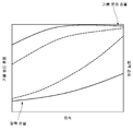
그 원인을 밝혀내기 위해서 면밀하게 검토한 결과, 도 1에 도시하는 바와 같이, 인입관으로부터 인입된 냉매의 대부분은 용기의 내주면을 따라 선회하고 있으나, 일부의 냉매가 선회 방향과 반대 방향으로 흐르고 있는 것을 알아냈다. 즉, 인입관에 의해 용기로 인입되는 냉매가 배출관에 의해 분기되어 기름의 분리 효율이 떨어지는 것을 알 수 있었다.As a result of careful examination to ascertain the cause, most of the refrigerant drawn in from the inlet pipe turns around the inner circumferential surface of the container as shown in Fig. 1, but a part of the refrigerant flows in the direction opposite to the swirling direction I found out. That is, it has been found that the refrigerant introduced into the vessel by the inlet pipe is diverted by the outlet pipe and the efficiency of oil separation is lowered.
본 발명은 상기와 같은 문제점을 감안하여 창안한 것으로서, 종래 기술에 의한 기름 분리기보다 기름의 분리 효율이 높은 기름 분리기에 관련된다.SUMMARY OF THE INVENTION The present invention has been made in view of the above problems, and it relates to an oil separator having a higher oil separation efficiency than an oil separator according to the prior art.
본 발명의 일 측면에 따르는 기름 분리기는, 기름 함유 냉매로부터 기름을 분리하는 것이며, 원통 형상의 내면을 구비한 용기와, 상기 용기의 외측에서 상기 용기의 내부로 관통하고, 상기 기름 함유 냉매가 상기 용기로 인입되는 인입구를 구비하며, 상기 기름 함유 냉매가 상기 용기의 내면을 따라 회전하면서 아래쪽으로 흐르게 할 수 있도록 형성된 인입관, 및 상기 용기의 상단에 상기 용기의 중심축과 동축 상에 설치되고, 상기 용기의 상단에서 상기 용기의 하단을 향해 돌출되며, 상기 인입구보다 아래에 위치하며 기름이 제거된 냉매가 배출되는 배출구를 구비하는 냉매 배출관;을 포함하며, 상기 인입관의 인입구에서 나오는 상기 기름 함유 냉매는 상기 냉매 배출관에 의해 분기되지 않고 상기 냉매 배출관의 외주면과 상기 용기의 내면을 따라 일 방향으로 흐르는 한 개의 흐름을 형성할 수 있다. An oil separator according to one aspect of the present invention separates oil from an oil-containing refrigerant and includes a container having a cylindrical inner surface, and an oil passage extending from the outside of the container to the inside of the container, An inlet pipe formed in the upper end of the vessel, the inlet pipe being provided with an inlet port for introducing the oil-containing refrigerant into the vessel and allowing the oil-containing refrigerant to flow downward while rotating along the inner surface of the vessel; And a refrigerant discharge pipe projecting from the upper end of the vessel toward the lower end of the vessel and having an outlet through which the refrigerant removed from the oil is discharged and located below the inlet, The refrigerant is not branched by the refrigerant discharge pipe but flows along the outer peripheral surface of the refrigerant discharge pipe and the inner surface of the container To form a single stream flowing in a direction.
이때, 상기 인입관의 관축을 포함하고, 상기 중심축에 직교하는 상기 기름 분리기의 단면에 있어서, 상기 인입관의 선단부는 상기 중심축에 평행한 제1가상 평면상에 위치하며, 상기 제1가상 평면과 상기 제1가상 평면과 평행하며 상기 냉매 배출관의 외주면에 접하는 제2가상 평면 사이의 이간 거리는 상기 인입관의 안지름의 적어도 0.32배일 수 있다. At this time, in the cross section of the oil separator including the tube of the intake pipe and perpendicular to the central axis, the leading end of the intake pipe is located on the first virtual plane parallel to the central axis, Plane and a second imaginary plane parallel to the first imaginary plane and in contact with the outer circumferential surface of the refrigerant discharge pipe may be at least 0.32 times the inner diameter of the inlet pipe.
이와 같이 구성된 기름 분리기라면, 제1가상 평면과 제2가상 평면 사이의 이간 거리가 인입관의 안지름의 0.32배 이상이기 때문에, 종래와 같이 냉매의 일부가 선회 방향과 반대 방향으로 흐르는 것을 방지할 수 있으므로 종래 기술에 의한 기름 분리기보다 분리 효율을 향상시킬 수 있다. 구체적인 실험 데이터에 대해서는 후술한다. Since the distance between the first imaginary plane and the second imaginary plane is 0.32 times or more of the inner diameter of the intake pipe, it is possible to prevent a part of the refrigerant from flowing in the direction opposite to the turning direction Therefore, the separation efficiency can be improved as compared with the conventional oil separator. Specific experimental data will be described later.
인입구로부터 인입되는 냉매를 보다 확실하게 용기의 내주면을 따라 선회시키기 위해서는, 상기 제1가상 평면이, 상기 관축과 직교하는 면에 대해 경사져 있으며, 상기 인입구가 상기 냉매 배출관을 향하도록 형성되어 있는 것이 바람직하다.It is preferable that the first imaginary plane is inclined with respect to a plane orthogonal to the tube axis and the inlet port is formed so as to face the refrigerant discharge pipe so as to more reliably rotate the refrigerant introduced from the inlet along the inner circumferential surface of the container Do.
여기서, 종래 기술에 의한 기름 분리기는, 기름이 분리되기 전에 기름 함유 냉매가 냉매 배출관으로 배출되어 버리는 것을 방지하기 위해, 냉매 배출관이 충분한 길이로 용기의 아래쪽으로 연장되는 것이 바람직하다.Here, it is preferable that the oil separator according to the related art is extended to the lower side of the container with a sufficient length so as to prevent the oil-containing refrigerant from being discharged to the refrigerant discharge pipe before the oil is separated.
그러나, 기름 분리기를 소형화하는 경우, 상술한 종래 기술에 의한 기름 분리기의 구성으로는, 냉매와 기름을 충분히 분리할 수 없다는 문제가 생긴다.However, when the size of the oil separator is reduced, there is a problem that the oil separator according to the above-described prior art can not sufficiently separate the refrigerant and the oil.
이 문제에 대해 본 발명자가 면밀하게 검토한 결과, 이하와 같은 것이 원인이라는 것을 발견했다.As a result of careful examination by the inventor of this problem, it has been found that the following is the cause.
즉, 기름 분리기의 소형화를 도모하기 위해 작은 사이즈의 용기를 이용하면, 냉매 배출관의 배출구로부터 용기의 내주면까지의 거리가 가까워지기 때문에, 종래 기술과 같이 냉매 배출관을 용기의 하 방향으로 연장한 구성으로는, 냉매가 용기의 내주면을 선회하는 사이에, 그 선회방향이 서서히 하 방향으로 변화해버려, 기름 함유 냉매가 냉매 배출관의 배출구 근방에 도달한 시점에서는 원심력이 저하되어 분리된 기름이 용기의 내주면으로부터 이탈하여 냉매 배출구에 흘러 들어가버리기 때문이다.That is, if a small-sized container is used to reduce the size of the oil separator, the distance from the outlet of the refrigerant discharge pipe to the inner circumferential surface of the container becomes close to each other. When the oil-containing refrigerant reaches the vicinity of the discharge port of the refrigerant discharge pipe, the centrifugal force is lowered and the oil separated from the inner peripheral surface of the container And flows into the refrigerant discharge port.
그래서, 본 발명의 일 실시예에 따른 기름 분리기는, 기름 함유 냉매로부터 기름을 분리하는 것이며, 원통 형상의 내면을 구비한 용기와, 상기 용기의 외측에서 상기 용기의 내부로 관통하고, 상기 기름 함유 냉매가 상기 용기로 인입되는 인입구를 구비하며, 상기 기름 함유 냉매가 상기 용기의 내면을 따라 회전하면서 아래쪽으로 흐르게 할 수 있도록 형성된 인입관, 및 상기 용기의 상단에 상기 용기의 중심축과 동축 상에 설치되고, 상기 용기의 상단에서 상기 용기의 하단을 향해 돌출되며, 상기 인입구보다 아래에 위치하며 기름이 제거된 냉매가 배출되는 배출구를 구비하는 냉매 배출관;을 포함하며, 상기 배출구로부터 상기 인입구의 중심까지의 높이가, 상기 인입관의 안지름의 3.0배 이상이고 4.5배 이하로 하는 것이 바람직하다.Therefore, an oil separator according to an embodiment of the present invention separates oil from oil-containing refrigerant, and includes a container having a cylindrical inner surface, and an oil passage pipe extending from the outside of the container to the inside of the container, An inlet pipe having an inlet through which the refrigerant is drawn into the container and which allows the oil-containing refrigerant to flow downward while rotating along the inner surface of the container; And a refrigerant discharge pipe protruding from the upper end of the container toward the lower end of the container and located below the inlet and discharging the refrigerant from which the oil has been removed, Is preferably 3.0 times or more and 4.5 times or less the inner diameter of the inlet pipe.
상술한 구성이라면, 배출구로부터 인입구의 중심까지의 높이가, 인입관의 안지름의 3.0배 이상이기 때문에, 인입관으로부터 인입된 기름 함유 냉매는, 용기의 내주면을 따라 선회하여 배출구의 높이에 도달하기까지는 기름이 분리된다. 게다가, 배출구로부터 인입구의 중심까지의 높이가 인입관의 안지름의 4.5배 이하이기 때문에, 배출구의 높이에 도달한 기름은 내주면을 선회하는 유속이 유지되고 있으므로 내주면으로부터 기름이 이탈하여 배출구로 흘러들어가 버리는 것을 방지할 수 있다.Since the height from the discharge port to the center of the inlet port is 3.0 times or more the inner diameter of the inlet pipe, the oil-containing refrigerant drawn from the inlet pipe must be circulated along the inner circumferential surface of the container until reaching the height of the discharge port Oil is separated. In addition, since the height from the discharge port to the center of the inlet port is 4.5 times or less the inner diameter of the inlet pipe, the oil that reaches the height of the discharge port maintains the flow rate of circling the inner circumferential surface, Can be prevented.
또한, 기름 분리 효율을 향상시키기 위한 구성으로서는, 상기 냉매 배출관이 상기 용기의 중심축과 동축상에 마련되어 있으며, 상기 냉매 배출관의 외주면과 상기 용기의 내주면과의 이간 거리가, 상기 냉매 배출관의 안지름의 1.0배 이상이고 2.0배 이하인 구성을 들 수 있다.In order to improve the oil separation efficiency, it is preferable that the refrigerant discharge pipe is provided coaxially with the central axis of the container, and the distance between the outer peripheral surface of the refrigerant discharge pipe and the inner peripheral surface of the container is smaller than the inner diameter of the refrigerant discharge pipe 1.0 times or more and 2.0 times or less.
이들의 구성에 관한 구체적인 실험 데이터는, 후술한다.Concrete experimental data on the construction of these will be described later.
압축기의 사이즈에 따라 토출되는 기름 함유 냉매의 양이 어느 정도 증감한 경우라도, 분리 효율을 줄이지 않기 위해서는, 상기 인입관의 안지름이, 상기 용기의 안지름의 0.16배 이상이고 0.44배 이하인 것이 바람직하다. It is preferable that the inner diameter of the inlet pipe is 0.16 times or more and 0.44 times or less of the inner diameter of the container so as not to reduce the separation efficiency even when the amount of the oil-containing refrigerant discharged increases or decreases according to the size of the compressor.
이때, 인입관의 안지름이 용기의 안지름의 0.16배보다 작으면 압력 손실이 커져 분리 효율이 줄어들게 되며, 인입관의 안지름이 용기의 안지름의 0.44배보다 크면 인입관이 용기의 중심에 가까워져서 기름 함유 냉매의 선회가 일어나기 어려워지며, 분리 효율이 줄어들게 된다.If the inner diameter of the inlet pipe is smaller than 0.16 times the inner diameter of the container, the pressure loss is increased to reduce the separation efficiency. If the inner diameter of the inlet pipe is larger than 0.44 times the inner diameter of the container, The rotation of the refrigerant is less likely to occur and the separation efficiency is reduced.
상기 인입관의 안지름이 9.5mm 이상이고 22.4mm 이하이며, 상기 용기의 중심축을 포함하고 상기 인입관의 관축과 직교하는 단면에 있어서, 상기 관축으로부터 상기 관축에 대해 상기 중심축과 반대쪽의 상기 용기의 내주면까지의 이간 거리가, 10.6mm 이상이고 13.2mm 이하인 것이 바람직하다.Wherein the inner diameter of the inlet pipe is 9.5 mm or more and 22.4 mm or less and includes a central axis of the container and is perpendicular to the tube axis of the inlet pipe, It is preferable that the spacing distance to the inner peripheral surface is not less than 10.6 mm and not more than 13.2 mm.
인입관의 관축과 용기의 내주면과의 이간 거리가 상기 범위 내라면, 기름 함유 냉매를 확실하게 선회시킬 수 있다.If the distance between the tube axis of the inlet pipe and the inner circumferential surface of the vessel is within the above range, the oil-containing refrigerant can be reliably pivoted.
상기 용기는 원통 형상의 본체부와 상기 본체부의 상단에 마련되며 상 방향으로 지름이 축소되는 상측 테이퍼부를 포함하며, 상기 본체부의 상단으로부터 상기 인입관의 관축까지의 높이는 상기 상측 테이퍼부의 높이보다 작은 것이 바람직하다.Wherein the container has a cylindrical main body and an upper tapered portion provided at an upper end of the main body and having a diameter reduced in an upward direction and a height from an upper end of the main body to a tube axis of the inlet pipe is smaller than a height of the upper tapered portion desirable.
이와 같은 구성이라면, 인입관의 상방에서 기름이 체류하기 어려워져서, 분리 효율을 더 향상시킬 수 있다.With this configuration, it is difficult for the oil to stay above the inlet pipe, so that the separation efficiency can be further improved.
상기 용기는 원통 형상의 본체부와, 상기 본체부의 하단에 마련되어 하측 방향으로 지름이 서서히 축소되며, 분리된 기름을 수용하는 하측 테이퍼부를 포함하며, 상기 냉매 배출관의 배출구가, 상기 하측 테이퍼부보다 위쪽에 마련되어 있는 것이 바람직하다. And a lower tapered portion provided at a lower end of the main body portion and gradually reduced in diameter in the downward direction and accommodating the separated oil, wherein the outlet of the refrigerant discharge pipe is located above the lower tapered portion As shown in Fig.
이와 같은 구성이라면, 하측 테이퍼부에 기름이 흘러들어가 수용되어 있던 기름이 비산(飛散)할 지라도, 배출구가 하측 테이퍼부보다 위쪽에 마련되어 있기 때문에, 비산된 기름이 배출구로 흘러들어가는 것이 어려워질 수 있다.With such a configuration, even if the oil flows into the lower tapered portion and the stored oil is scattered, since the discharge port is provided above the lower tapered portion, it is difficult for the scattered oil to flow into the discharge port .
상기 인입관은, 상기 인입구가 형성되며 상기 용기의 측벽을 관통하는 선단부와, 상기 선단부의 상류측에 마련되며, 상기 선단부로부터 만곡되어 상 방향으로 연장되는 후단부를 갖는 것이 바람직하다.It is preferable that the inlet pipe has a front end portion formed with the inlet port and passing through the side wall of the container and a rear end portion provided on the upstream side of the front end portion and curved upward from the front end portion and extending upward.
이와 같은 구성이라면, 후단부가 선단부로부터 만곡되어 상 방향으로 연장되어 있기 때문에, 인입관 내의 내주면에 따라 흐르는 기름은, 후단부의 만곡된 부분에서 원심력에 의해 하측으로 기울어져 흐르게 된다. With this configuration, since the rear end portion is curved from the front end portion and extends upward, oil flowing along the inner circumferential surface of the inlet pipe is tilted downward due to the centrifugal force at the curved portion of the rear end portion.
이로 인해, 기름이 인입구로부터 용기 내의 상 방향을 향해서 인입되는 것을 방지할 수 있고, 인입관의 상측에 기름이 체류하는 것을 어렵게 할 수 있다.As a result, it is possible to prevent the oil from being drawn in from the inlet toward the upward direction in the vessel, making it difficult for the oil to stay above the inlet tube.
분리된 기름의 비산을 방지하기 위해서는, 상기 용기 내부의 하부에 설치되어 상기 용기 내부를 상하로 구획하며, 상기 기름 함유 냉매에서 분리된 기름을 통과시키는 적어도 한 개의 기름 통과구멍이 형성된 기름 비산 방지 플레이트를 더 구비하는 것이 바람직하다.In order to prevent scattering of the separated oil, it is preferable to provide an oil dissipation prevention plate having at least one oil passage hole formed at a lower portion of the container to divide the inside of the container vertically and to allow oil separated from the oil- As shown in Fig.
상기 기름 비산 방지 플레이트는 외주면이 상기 용기의 내주면에 대응하는 원판 형상으로 형성되며, 상기 적어도 한 개의 기름 통과구가 상기 외주면에 형성되어 있는 것이 바람직하다.It is preferable that the oil splash prevention plate has a circular plate shape having an outer peripheral surface corresponding to an inner peripheral surface of the container, and the at least one oil passage hole is formed in the outer peripheral surface.
이와 같은 것이라면, 분리된 기름을 용기의 내주면을 따라 기름 통과구를 통해 아래로 흐르게 할 수 있고, 기름의 비산을 더 확실하게 방지할 수 있다. In such a case, the separated oil can flow downward through the oil passage along the inner circumferential surface of the container, and oil scattering can be more reliably prevented.
도 1은 종래 기술에 의한 기름 분리기에서 기름 함유 냉매의 흐름을 시뮬레이션한 도면이다.
도 2는 본 발명의 일 실시예에 의한 냉매 회로를 모식적으로 나타내는 회로도이다.
도 3은 본 발명의 일 실시예에 의한 기름 분리기를 모식적으로 나타내는 도면이다.
도 4는 본 발명의 일 실시예에 의한 기름 분리기를 나타내는 단면도이다.
도 5는 본 발명의 일 실시예에 의한 기름 분리기를 나타내는 단면도이다.
도 6은 본 발명의 일 실시예에 의한 기름 분리기의 효과를 나타내는 실험 데이터이다.
도 7은 본 발명의 일 실시예에 의한 기름 분리기의 기름 함유 냉매의 흐름을 시뮬레이션한 결과를 나타낸 도면이다.
도 8은 본 발명의 일 실시예에 의한 기름 분리기의 효과를 나타내는 실험 데이터이다.
도 9는 본 발명의 일 실시예에 의한 기름 분리기의 효과를 나타내는 실험 데이터이다.
도 10은 본 발명의 일 실시예에 의한 기름 분리기의 효과를 나타내는 실험 데이터이다.
도 11은 본 발명의 다른 실시예에 의한 기름 분리기를 모식적으로 나타내는 도면이다.
도 12는 본 발명의 다른 실시예에 의한 기름 분리기를 모식적으로 나타내는 도면이다.
도 13은 도 12의 기름 분리기를 선 A-A'를 따라 절단한 단면도이다.
도 14는 본 발명의 다른 실시예에 의한 기름 분리기를 모식적으로 나타내는 단면도이다.1 is a graph simulating the flow of oil-containing refrigerant in an oil separator according to the prior art.
2 is a circuit diagram schematically showing a refrigerant circuit according to an embodiment of the present invention.
3 is a view schematically showing an oil separator according to an embodiment of the present invention.
4 is a cross-sectional view illustrating an oil separator according to an embodiment of the present invention.
5 is a cross-sectional view illustrating an oil separator according to an embodiment of the present invention.
6 is experimental data showing the effect of the oil separator according to an embodiment of the present invention.
7 is a graph showing a result of simulating the flow of oil-containing refrigerant in the oil separator according to an embodiment of the present invention.
8 is experimental data showing the effect of the oil separator according to an embodiment of the present invention.
9 is experimental data showing the effect of the oil separator according to an embodiment of the present invention.
10 is experimental data showing the effect of the oil separator according to an embodiment of the present invention.
11 is a view schematically showing an oil separator according to another embodiment of the present invention.
12 is a view schematically showing an oil separator according to another embodiment of the present invention.
13 is a cross-sectional view of the oil separator of Fig. 12 cut along the line A-A '.
14 is a sectional view schematically showing an oil separator according to another embodiment of the present invention.
이하, 첨부된 도면을 참조하여 본 발명에 의한 기름 분리기의 실시예들에 대해 상세하게 설명한다.Hereinafter, embodiments of the oil separator according to the present invention will be described in detail with reference to the accompanying drawings.
이하에서 설명되는 실시 예는 본 발명의 이해를 돕기 위하여 예시적으로 나타낸 것이며, 본 발명은 여기서 설명되는 실시 예들과 다르게 다양하게 변형되어 실시될 수 있음이 이해되어야 할 것이다. 다만, 이하에서 본 발명을 설명함에 있어서, 관련된 공지 기능 혹은 구성요소에 대한 구체적인 설명이 본 발명의 요지를 불필요하게 흐릴 수 있다고 판단되는 경우 그 상세한 설명 및 구체적인 도시를 생략한다. 또한, 첨부된 도면은 발명의 이해를 돕기 위하여 실제 축척대로 도시된 것이 아니라 일부 구성요소의 치수가 과장되게 도시될 수 있다.It is to be understood that the embodiments described below are provided for illustrative purposes only, and that the present invention may be embodied with various modifications and alterations of the embodiments described herein. In the following description, well-known functions or components are not described in detail to avoid obscuring the subject matter of the present invention. In addition, the attached drawings are not drawn to scale in order to facilitate understanding of the invention, but the dimensions of some of the components may be exaggerated.
도 2는 본 발명의 일 실시예에 의한 냉매 회로를 모식적으로 나타내는 회로도이다.2 is a circuit diagram schematically showing a refrigerant circuit according to an embodiment of the present invention.
도 2에 도시된 바와 같이, 본 발명의 일 실시예에 따르는 기름 분리기(100)는 압축기(C), 어큐뮬레이터(A) 등과 함께 공기 조화장치의 냉매 회로(200)를 구성할 수 있다. 이러한 기름 분리기(100)는 압축기(C)의 하류 측에 배치되고, 압축기(C)로부터 토출된 기름을 포함한 냉매(이하, 기름 함유 냉매라고도 한다)로부터 기름을 분리한다.2, the
더욱 상세하게, 기름 분리기는 원심력을 이용하여 기름 함유 냉매로부터 기름을 원심 분리시키고, 기름을 분리시킨 후의 냉매(이하, 분리 후 냉매라고도 한다)를 예를 들면 미도시의 열교환기로 배출함과 동시에, 분리시킨 기름을 다시 압축기(C)로 되돌리도록 구성되어 있다.More specifically, the oil separator centrifips the oil from the oil-containing refrigerant by centrifugal force, discharges the refrigerant after separation of the oil (hereinafter, also referred to as refrigerant after separation) into a heat exchanger, for example, And the separated oil is returned to the compressor (C) again.
또한, 상기 냉매 회로(200)는 기름 분리기(100)와 압축기(C)를 연결하며 분리된 기름을 압축기(C)로 되돌리기 위한 되돌림 배관(B)과, 이 되돌림 배관(B)에 마련된 모세 배관(T)을 구비한다. 분리된 기름의 거의 전부는 모세 배관(T)을 흘러 압축기(C)로 되돌아가도록 구성되어 있다.The
구체적으로 설명하면, 상기 기름 분리기(100)는, 도 3 내지 도 5에 도시된 바와 같이, 기름 함유 냉매로부터 기름을 분리시키기 위한 분리 공간(S)을 갖는 용기(10)와, 기름 함유 냉매를 용기(10)의 내부로 유입시키는 인입관(20)과, 분리 후 냉매를 용기(10)로부터 배출하는 냉매 배출관(30)과, 분리시킨 기름을 용기(10)로부터 배출하는 기름 배출관(40)을 포함할 수 있다.3 to 5, the
이하, 도 3 내지 도 5를 참조하여 본 발명의 일 실시예에 의한 기름 분리기(100)에 대해 상세하게 설명한다.Hereinafter, the
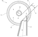
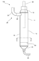
도 3은 본 발명의 일 실시예에 의한 기름 분리기를 모식적으로 나타내는 도면이다. 도 4는 본 발명의 일 실시예에 의한 기름 분리기를 나타내는 단면도이다. 도 5는 본 발명의 일 실시예에 의한 기름 분리기를 나타내는 단면도이다.3 is a view schematically showing an oil separator according to an embodiment of the present invention. 4 is a cross-sectional view illustrating an oil separator according to an embodiment of the present invention. 5 is a cross-sectional view illustrating an oil separator according to an embodiment of the present invention.
도 3에 도시된 바와 같이, 용기(10)는 상단 및 하단이 개구된 대략 원통 형상으로 형성되며, 동일한 단면 형상의 본체부(11)와, 본체부(11)의 상단에 마련되어 상측 방향을 향해 서서히 지름이 감소하는 상측 테이퍼부(12)와, 본체부(11)의 하단에 마련되어 하측 방향을 향해 서서히 지름이 감소하는 하측 테이퍼부(13)를 포함한다. 하측 테이퍼부(13)는 용기(10)에서 분리된 기름을 수용한다. 3, the
용기(10)는, 도 4 및 도 5에 도시된 바와 같이, 용기(10)의 중심축(O1)에 직교하는 단면이 원 형상을 이루는 내주면(14)을 갖는다. 내주면(14)에 의해 용기의 분리 공간(S)이 형성된다. 기름 함유 냉매는 용기(10)의 내주면(14)을 따라 선회하면서 위쪽에서 아래쪽으로 흐르게 된다.4 and 5, the
도 3 및 도 4에 도시된 바와 같이, 인입관(20)은 기름 함유 냉매가 용기(10)의 내주면(14)을 따라 선회하도록 상기 용기(10) 내부로 인입시키는 것이며, 용기(10)의 측벽(15)을 관통하도록 설치된다. 본 실시예에 따르는 인입관(20)은 상측 테이퍼부(12)의 아래쪽, 더욱 상세하게는 본체부(11)의 상단부를 관통하여 용기(10)의 내부로 돌출되며, 인입관(20)의 관축(O2)이 용기(10)의 중심축(O1)에 대해 직교하도록 설치된다.3 and 4, the
구체적으로, 인입관(20)은 기름 함유 냉매를 용기(10) 내부에 인입시키는 인입구(21)를 가지며, 단면이 원형상인 원통관으로 형성된다. 인입관(20)은 인입구(21)가 형성되며, 용기(10)의 측벽(15)을 관통하여 선단이 용기의 내부에 위치하는 선단부(22)와 상기 선단부(22)의 상류측으로 연속으로 마련된 후단부를 포함한다. 후단부(23)는 선단부(22)로부터 높이 방향으로 만곡되어 상 방향으로 연장되도록 형성된다.Specifically, the
더욱 상세히 설명하면, 인입관(20)은 기름 함유 냉매가 인입구(21)로부터 내주면(14)의 접선방향으로 토출되도록 인입관(20)의 선단부(22)의 관축(O2)과 용기(10)의 중심축(O1)이 교차하지 않도록 설치된다. 즉, 선단부의 관축(O2)은 용기의 중심축(O1)에서 이격되도록 설치된다. 여기서, 선단부(22)의 관축(O2)이 상기 용기의 중심축(O1)과 직교하고, 선단부(22)의 관축(O2)과 상기 후단부(23)의 직선 부분의 관축(O3)이 이루는 각도 θ가 대략 90도가 되도록 하고 있다. 또한, 인입관(20)의 선단부(22)와 후단부(23) 사이의 각도 θ는 0도보다 크고 180도보다 작은 범위에서 적절하게 변경할 수 있다. More specifically, the
본 실시예에 있어서는, 도 4를 참조하면, 인입관(20)의 관축(O2)을 포함하며 용기(10)의 중심축(O1)에 직교하는 단면에서, 상기 관축(O2)을 사이에 둔 인입관(20)의 선단(20a)이 용기(10)의 중심축(O1)에 평행한 제1가상 평면(X1)상에 위치한다. 4, in the cross section perpendicular to the center axis O1 of the
더욱 구체적으로는, 상기 인입구(21)는 용기(10)의 중심축(O1)과 평행인 제1 가상 평면(X1)상에 형성되어 있으며, 냉매 배출관(30)의 외주면(31)을 마주하도록 인입관(20)의 관축(O2)에 직교하는 가상의 평면(X3)에 대해 경사지게 개구되어 있다.More specifically, the
냉매 배출관(30)은 기름이 제거된 분리 후 냉매가 아래에서 위쪽으로 흐르는 것이며, 도 4 및 도 5에 도시된 바와 같이, 용기(10)의 상단에 형성된 개구(미도시)에 안정되게 삽입되며, 용기(10)의 중심축(O1)과 동축상으로 설치된다.The
구체적으로, 냉매 배출관(30)은 바깥지름이 용기(10)의 안지름보다 작은 등단면 형상의 원통관으로 형성되며, 상기 용기(10) 내부에 위치하며 분리 후 냉매가 인입되는 배출구(32)를 구비한다. 즉, 냉매 배출관(30)은 용기(10)의 상단에 용기의 중심축(O1)과 동축 상에 설치되고, 용기(10)의 상단에서 용기(10)의 하단을 향해 돌출되며, 인입구(21)보다 아래에 위치하며 기름이 제거된 냉매가 배출되는 배출구(32)를 구비한다. Specifically, the
냉매 배출관(30)의 배출구(32)는 용기(10)의 상단으로부터 일정 거리의 위치에 마련되어 있다. 본 실시예에서는 배출구(32)보다 아래의 용기(1)의 내부 체적이 0.6L 이하가 되도록 배출구가 위치한다.The
또한, 본 실시예에서는, 배출구(32)가 상술한 하측 테이퍼부(13)보다 위쪽, 즉 본체부(11)의 하단보다 위쪽에 위치하도록 마련되어 있다. 따라서, 하측 테이퍼부(13)에 수용된 기름이 비산된 경우에도, 비산된 기름이 배출구(32) 내에 흘러들어가지 않게 된다.In the present embodiment, the
기름 배출관(40)은 용기(10)의 하측 테이퍼부(13)에 고인 기름을 용기(10)로부터 외부로 배출하는 것이며, 도 3에 도시된 바와 같이, 하측 테이퍼부(13)에 마련된다.The
구체적으로 기름 배출관(40)은 용기(10)의 하단에 형성된 하단 개구(미도시)에 안정적으로 삽입되며, 등단면 형상의 원통관으로 형성된다.Specifically, the
본 발명의 일 실시예에 따르는 기름 분리기(100)는 상기 인입관(20)의 인입구(21)에서 나오는 기름 함유 냉매가 냉매 배출관(30)에 의해 2개의 냉매 흐름으로 분기되지 않고 도 7에 도시된 바와 같이 냉매 배출관(30)의 외주면(31)과 용기(10)의 내주면(14)을 따라 일 방향으로 흐르는 한 개의 냉매 흐름을 형성하도록 형성된다. 일 예로서, 도 4에 도시된 도면에서, 용기(10)의 중심축(O1)에 인접한 인입구(21)의 일단(21a)에서 연장되며 관축(O2)과 평행한 가상의 직선(21b)이 상기 냉매 배출관(30)의 외주면(31)과 간섭되면서도 상기 중심축(O1)을 넘지 않도록 인입관(20)을 설치할 수 있다. The
도 3에 도시된 바와 같이, 본 실시예에 의한 기름 분리기(100)는 제1가상 평면(X1)과, 제1가상 평면(X1)에 평행하게 냉매 배출관(30)의 외주면(31)에 접하는 제2가상 평면(X2) 사이의 이간 거리(L1)가 상기 인입관(20)의 안지름(D1)의 0.32배 이상이 되도록 구성되어 있다.3, the
더 상세하게는, 상기 이간 거리(L1)는 상기 인입관(20)에서 인입구측 단부의 안지름(D1)의 0.32배 이상이다.More specifically, the separation distance L1 is 0.32 times or more of the inside diameter D1 of the inlet side end portion in the
여기서, 제1가상 평면(X1)과 제2가상 평면(X2) 사이의 이간 거리(L1)와 기름 분리 효율과의 관계를 나타내는 실험 데이터의 그래프를 도 6에 도시하고, 기름 함유 냉매의 흐름을 시뮬레이션한 결과를 도 7에 도시한다. 6 shows a graph of experimental data showing the relationship between the separation distance L1 between the first virtual plane X1 and the second virtual plane X2 and the oil separation efficiency, The result of the simulation is shown in Fig.
또한, 도 6에 도시된 실험 데이터는, 기름 분리기(100)에 도입되는 기름 유량(냉매 유량에 기름 윤활율을 곱한 것)이 많은 상태를 가정한 것이며, 실험 조건은, 냉매 유량이 1000kg/h, 기름 윤활율이 1.4%, 인입관(20)의 안지름(D1)이 17.05mm이다. 또, 도 7에 도시된 도면은 상기 이간 거리(L1)를 인입관(20)의 안지름(D1)의 0.32배로 한 조건으로 수행한 컴퓨터 시뮬레이션 결과를 나타낸다.The experimental data shown in Fig. 6 assumes that the oil flow rate (the refrigerant flow rate multiplied by the oil lubrication rate) introduced into the
도 6에 도시된 실험 데이터의 그래프에서 알 수 있는 바와 같이, 상기 이간 거리(L1)를 서서히 증가시키면, 인입관(20)의 안지름(D1)의 약 0.32배가 되기까지 기름 분리 효율이 향상되고, 0.32배 이상에서는 기름 분리 효율이 거의 변동하지 않는 경향을 볼 수 있다.As can be seen from the graph of the experimental data shown in FIG. 6, when the separation distance L1 is gradually increased, the oil separation efficiency is improved to about 0.32 times the inner diameter D1 of the
이와 같은 경향은, 상기 이간 거리(L1)가 인입관(20)의 안지름(D1)의 0.32배 이상이 되면, 도 7에 도시된 바와 같이, 인입관(20)으로 인입된 기름 함유 냉매의 거의 전부가 냉매 배출관(30)에 대해 좌측 또는 우측의 한쪽으로만 흘러 동일 방향으로 선회하기 때문에 발생한다. 도 7의 경우에는 인입관(20)으로 인입된 기름 함유 냉매의 거의 전부는 냉매 배출관(30)의 우측으로만 흘러 반시계방향으로 선회한다.This tendency is such that when the separation distance L1 becomes 0.32 times or more of the inner diameter D1 of the
또한, 본 실시예의 기름 분리기(100)는 배출구(32)로부터 인입구(21)의 중심까지의 높이, 즉 배출구(32)로부터 인입관(20)의 관축(O2)까지의 높이(L2)가, 인입관(20)의 안지름(D1)의 3.0배 이상이고 4.6배 이하가 되도록 구성될 수 있다. 더욱 구체적으로는, 배출구(32)로부터 인입관(20)의 관축(O2)까지의 높이(L2)는 인입관(20)의 안지름(D1)의 3.0배 이상이고 4.0배 이하로 할 수 있다.The
여기서, 상기 높이(L2)와 기름 분리 효율과의 관계를 나타내는 실험 데이터그래프를 도 8에 도시한다. 또한, 실험 조건은, 상술한 기름 분리기(100)의 실험 조건과 동일하다.Here, FIG. 8 shows a graph of experimental data showing the relationship between the height L2 and the oil separation efficiency. The experimental conditions are the same as the experimental conditions of the
도 8에 도시된 실험 데이터 그래프에서 알 수 있는 바와 같이, 기름 분리기(100)의 기름 분리 효율은, 상기 높이(L2)가 증가함에 따라 상승한다. 그러나 상기 높이(L2)가 인입관(20)의 안지름(D1)의 3.0배 이상이 되면 기름 분리 효율은 거의 변동이 없고, 상기 높기(L2)가 안지름(D1)의 4.0배 이상이 되면 기름 분리 효율이 서서히 저하되는 경향을 볼 수 있다.As can be seen from the experimental data graph shown in FIG. 8, the oil separation efficiency of the
이러한 경향은 상기 높이(L2)가 인입관(20)의 안지름(D1)의 3.0배보다 작으면, 기름 함유 냉매로부터 기름이 분리되기 전에 냉매 배출관(30)으로 냉매와 함께 기름이 배출되기 때문에 발생한다. 또한, 상기 높이(L2)가 인입관(20)의 안지름(D1)의 4.0배보다 크면, 인입관(20)으로 인입된 냉매가 용기(10)의 내주면(14)을 따라 선회하는 동안에, 냉매의 선회 방향이 서서히 아래 방향으로 바뀌게 되고, 기름 함유 냉매가 냉매 배출관(30)의 배출구(32) 근처에 도달한 시점에서는 원심력이 저하되어 있어, 분리된 기름이 용기(10)의 내주면(14)에서 이탈되어 배출구(32)로 흘러들어가 버리기 때문에 발생한다.If the height L2 is smaller than 3.0 times the inner diameter D1 of the
또한, 본 실시예에서는, 배출구(32)로부터 인입관(20)의 관축(O2)까지의 높이(L2)는 인입관(20)을 흐르는 냉매 유량, 냉매 배출관(30)의 외주면(31)과 용기(10)의 내주면(14) 사이의 이간 거리(L3), 및 인입관(20)의 안지름(D1)을 파라미터로 하여 설정할 수도 있다.In the present embodiment, the height L2 from the
구체적으로, 인입관(20)으로 유입되는 냉매가 6 m/s 이상이며, 상기 이간 거리(L3)가 냉매 배출관(30)의 안지름(D2)의 1.0배 이상이고 2.0배 이하인 경우에, 상기 높이(L2)는 상술한 바와 같이 인입관(20)의 안지름(D1)의 3.0배 이상이고 4.0배 이하가 되도록 설정될 수 있다. 이와 같이 구성하면, 기름 분리기(100)를 소형화하면서도, 기름 분리 효율을 향상시킬 수 있다.Specifically, when the refrigerant flowing into the
여기서, 냉매 배출관(30)의 외주면(31)과 용기(10)의 내주면(14) 사이의 이간 거리(L3)와 기름 분리 효율과의 관계를 도 9에 도시한다. 이때, 실험 조건은 상술한 기름 분리기(100)의 실험 조건과 동일하다.9 shows the relationship between the separation distance L3 between the outer
도 9에 도시된 실험 데이터의 그래프에서 알 수 있는 바와 같이, 기름 분리 효율은, 상기 이간 거리(L3)가 냉매 배출관(30)의 안지름(D2)의 1.0배 이상이 되면 크게 상승하는 경향을 볼 수 있다.As can be seen from the graph of the experimental data shown in FIG. 9, the oil separation efficiency tends to increase significantly when the separation distance L3 is 1.0 times or more the inner diameter D2 of the
이러한 경향은, 상기 이간 거리(L3)가 배출관(30)의 안지름(D2)의 1.0배보다도 짧으면, 분리된 기름이 냉매 배출관(30)의 배출구(32)로 흘러들어가 버리기 때문에 발생한다. This tendency is caused because the separated oil flows into the
또한, 본 발명의 일 실시예에 의한 기름 분리기(100)는, 인입관(20)의 안지름(D1)을 용기(10)의 안지름(D3)의 0.16배 이상이고 0.44배 이하로 할 수 있다. 여기서는, 용기(10)의 안지름(D3)은 예를 들면 50.8mm이다.The
더욱 구체적으로 설명하면, 인입관(20)의 안지름(D1)은 9.5mm 이상이고 22.4mm 이하로 할 수 있다. 또한, 용기(10)의 중심축(O1)을 포함하고 인입관(20)의 관축(O2)과 직교하는 단면에서, 상기 관축(O2)으로부터 상기 관축(O2)에 대해 중심축(O1)과 반대쪽의 내주면(14)까지의 이간 거리(L4)는 10.6mm 이상이고 13.2mm 이하가 되도록 할 수 있다. More specifically, the inner diameter D1 of the
이와 같이 인입관(20)을 형성하면, 인입관(20)으로부터 용기(10)로 인입되는 기름 함유 냉매가 확실하게 용기(10)의 내주면(14)을 따라 선회하도록 할 수 있으며, 기름 분리 효율을 향상시킬 수 있다.By forming the
게다가, 본 실시예에서는, 인입관(20)의 위쪽에 기름이 체류하는 것을 방지하기 위해, 본체부(11)의 상단, 즉 상측 테이퍼부(12)의 하단으로부터 인입관(20)의 관축(O2)까지의 높이(L5)가 상측 테이퍼부(12)의 높이(L6)보다 작도록 형성할 수 있다.In order to prevent the oil from staying above the
여기서, 본 실시예의 기름 분리기(100)와 종래 기술에 의한 기름 분리기를 비교한 실험 데이터 그래프를 도 10에 도시한다.Here, FIG. 10 shows a graph of an experimental data comparing the
도 10의 실험 데이터 그래프에서 알 수 있는 바와 같이, 본 실시예에 따른 기름 분리기(100)에 따르면, 인입관(20)으로 인입된 기름 함유 냉매의 일부가 종래 기술에 의한 기름 분리기와 같이 선회 방향과 반대 방향으로 흐르는 것을 방지할 수 있기 때문에 종래 기술에 의한 기름 분리기에 비해 압력 손실을 감소시킬 수 있다. 참고로, 도 10에서 점선은 종래 기술에 의한 기름 분리기의 압력 손실과 기름 분리 효율을 나타내고, 실선은 본 발명의 일 실시예에 의한 기름 분리기(100)의 압력 손실과 기름 분리 효율을 나타낸다. 10, according to the
따라서, 기름 분리기(100)로 인입되는 기름 함유 냉매의 유속을 빠르게 한 경우라도 압력 손실을 억제할 수 있으며, 빠른 유속에 따른 큰 원심력을 이용하여 기름을 효율적으로 분리시킬 수 있고, 나아가 기름 분리기(100)를 소형화하는 것이 가능해진다.Accordingly, even when the flow rate of the oil-containing refrigerant flowing into the
또한, 기름 분리기(100)를 소형화하여, 특히 본 실시예와 같이 냉매 배출관(30)의 배출구(32) 아래의 용기(10)의 체적을 0.6L 이하로 한 경우에, 기름 분리기(100)에는 분리된 기름을 담아 두는 공간이 작아진다. 이로 인해, 분리된 기름 양이 많은 경우는, 기름 배출관(40)뿐 아니라 냉매 배출관(30)으로 기름이 흘러들어가 버리게 되는 문제가 발생할 수 있다.When the volume of the
그래서, 종래 기술에 의한 소형 기름 분리기를 사용하는 경우에는, 냉매 회로에 모세 배관에 병렬로 마련된 바이패스관과, 이 바이패스관에 마련된 전자(電磁) 밸브를 설치하여, 예를 들면 압축기의 기동시 등과 같이 기름 함유 냉매에 포함되는 기름 양이 많을 때에, 상기 전자 밸브를 열어 기름 분리기에 의해 분리된 기름이 확실하게 압축기로 되돌려 질 수 있도록 하고 있다.Therefore, in the case of using the conventional small oil separator, a bypass pipe provided in parallel with the capillary piping and an electromagnetic valve provided in the bypass pipe are provided in the refrigerant circuit, for example, When the amount of oil contained in the oil-containing refrigerant is large, such as when the oil is contained in the oil-containing refrigerant, the electromagnetic valve is opened to reliably return the oil separated by the oil separator to the compressor.
이에 비해, 본 실시예에 따르는 냉매 회로(200)는 종래 기술에 의한 냉매 회로보다 지름이 큰 모세 배관을 이용함으로써, 분리된 기름을 확실하게 압축기(C)로 되돌릴 수 있도록 구성되어 있다. 따라서, 본 발명에 의한 냉매 회로(200)는 전자 밸브가 필요하지 않기 때문에 비용을 절감할 수 있다.On the other hand, the
또한, 본 발명에 따르는 기름 분리기(100)는 상술한 실시예에 한정되는 것이 아니다.Further, the
예를 들면, 상술한 실시예에서는, 인입관이 등단면 형상의 원통관이었으나, 다른 실시예에 의한 기름 분리기(100)는, 도 11에 도시된 바와 같이, 인입관(20)은 인입구(21)를 향해 서서히 지름이 줄어드는 축경부를 갖도록 형성할 수 있다.11, in the
이 경우, 제1가상 평면(X1)과 제2가상 평면(X2) 사이의 이간 거리(L1)는 인입관(20)의 선단부의 내경(D1)의 0.32배 이상으로 할 수 있다.In this case, the distance L1 between the first imaginary plane X1 and the second imaginary plane X2 may be 0.32 times or more of the inner diameter D1 of the leading end portion of the
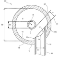
또, 다른 실시예로서, 기름 분리기(100)는, 도 12에 도시된 바와 같이, 용기(10) 내부의 하부에 마련되어 분리 공간(S)을 상하로 칸막이하여 구획하는 기름 비산 방지 플레이트(50)를 더 포함할 수 있다.12, the
이 기름 비산 방지 플레이트(50)는 하측 테이퍼부(13)보다 상측에 예를 들면 용접 등으로 고정되어 있으며, 분리된 기름을 위쪽에서 아래쪽으로 통과시키는 적어도 한 개의 기름 통과구(51)가 형성된 판형상으로 형성될 수 있다.The oil
더욱 구체적으로, 도 13을 참조하면, 기름 비산 방지 플레이트(50)는 외주면이 용기(10)의 내주면(14)에 대응하는 원판 형상을 이루며, 그 외주면에는 적어도 한 개의 기름 통과구(51)를 형성할 수 있다. 예를 들면, 기름 비산 방지 플레이트(50)의 원주 방향으로 등 간격으로 복수의 기름 통과구(51)를 형성할 수 있다. 도 13의 경우에는, 기름 비산 방지 플레이트(50)에 4개의 기름 통과구(51)를 형성하였으나, 기름 통과구(51)의 개수는 적절하게 변경할 수 있다.13, the oil
상술한 실시예에 따르는 기름 분리기(100)에서는, 인입관(20)의 인입구(21)가 제1가상 평면(X1)상에 형성되어 있으나, 인입구(21)의 형상은 이에 한정되지 않는다. 도 14에 도시된 바와 같이, 다른 실시예에 의한 기름 분리기(100)의 인입구(21)는 인입관(20)의 선단에서 인입관(20)의 안쪽으로 만곡된 형상으로 형성하고, 제1가상 평면(X1)상에 형성하지 않을 수 있다.The
또, 상술한 실시예에 따르는 기름 분리기의 인입관은 그 관축이 용기의 중심축과 직교하도록 설치되어 있으나, 상기 관축이 상기 중심축과 직교하는 방향에 대해 하향 또는 상향으로 경사지게 설치될 수도 있다.The inlet pipe of the oil separator according to the above-described embodiment is installed such that its tube axis is orthogonal to the center axis of the vessel, but the tube axis may be inclined downward or upward with respect to a direction orthogonal to the center axis.
또한, 상술한 실시예에 따르는 기름 분리기의 기름 배출관은 용기의 바닥을 관통하도록 설치되어 있으나, 기름 배출관은 용기의 하부에 마련되어 있으면 좋으며, 용기의 측벽의 하부를 관통하도록 설치할 수도 있다.Further, the oil discharge pipe of the oil separator according to the above-described embodiment is installed to penetrate the bottom of the container, but the oil discharge pipe may be provided at the lower part of the container, or may be installed to penetrate the lower part of the side wall of the container.
게다가, 상술한 실시예에 따르는 기름 분리기의 용기는 원통 형상으로 형성되어 있으나, 용기의 형상은 이에 한정되지 않는다. 용기는 중심축에 직교하게 절단한 단면이 원형상의 내주면을 갖고 있으면 되며, 외형은 다양한 형상으로 형성될 수 있다. 예를 들면, 용기의 외형은 사각기둥 형상이나 다각 기둥 형상으로 형성할 수도 있다. In addition, although the container of the oil separator according to the above-described embodiment is formed in a cylindrical shape, the shape of the container is not limited thereto. It is sufficient that the container has a circular inner circumferential surface whose cross section cut perpendicularly to the central axis has a circular shape, and the outer shape can be formed in various shapes. For example, the outer shape of the container may be formed into a rectangular columnar shape or a polygonal columnar shape.
이상에서 본 발명은 예시적인 방법으로 설명되었다. 여기서 사용된 용어들은 설명을 위한 것이며, 한정의 의미로 이해되어서는 안 될 것이다. 상기 내용에 따라 본 발명은 다양하게 수정 및 변형을 할 수 있다. 따라서 따로 부가 언급하지 않는 한 본 발명은 청구범위의 범주 내에서 자유로이 실시될 수 있을 것이다.The present invention has been described above by way of example. The terms used herein are for the purpose of description and should not be construed as limiting. The present invention can be variously modified and modified in accordance with the above description. Therefore, unless otherwise indicated, the present invention may be practiced freely within the scope of the claims.
10; 용기
11; 본체부
12; 상측 테이퍼부
13; 하측 테이퍼부
14; 내주면
20; 인입관
21; 인입구
22; 선단부
23; 후단부
30; 냉매 배출관
31; 외주면
32; 배출구
50; 기름 비산 방지 플레이트
51; 기름 통과구
100; 기름 분리기
200; 냉매 회로
X1; 제1가상 평면
X2; 제2가상 평면10;
12; An upper tapered
14; Inner
21;
23; A
31; An outer
50; Oil scattering
100;
X1; A first virtual plane X2; The second virtual plane
Claims (17)
원통 형상의 내주면을 구비한 용기;
상기 용기의 외측에서 상기 용기의 내부로 관통하고, 상기 기름 함유 냉매가 상기 용기로 인입되는 인입구를 구비하며, 상기 기름 함유 냉매가 상기 용기의 내주면을 따라 회전하면서 아래쪽으로 흐르게 할 수 있도록 형성된 인입관; 및
상기 용기의 상단에 상기 용기의 중심축과 동축 상에 설치되고, 상기 용기의 상단에서 상기 용기의 하단을 향해 돌출되며, 상기 인입구보다 아래에 위치하며 기름이 제거된 냉매가 배출되는 배출구를 구비하는 냉매 배출관;을 포함하며,
상기 인입관의 인입구에서 나오는 상기 기름 함유 냉매는 상기 냉매 배출관에 의해 분기되지 않고 상기 냉매 배출관의 외주면과 상기 용기의 내주면을 따라 일 방향으로 흐르는 한 개의 흐름을 형성하는, 기름 분리기.An oil separator for separating oil from oil-containing refrigerant,
A container having a cylindrical inner peripheral surface;
And an inlet port through which the oil-containing refrigerant flows into the container from the outside of the container to the inside of the container, the oil-containing refrigerant flowing downward along the inner circumferential surface of the container, ; And
And a discharge port provided coaxially with the center axis of the vessel at the upper end of the vessel and protruding from the upper end of the vessel toward the lower end of the vessel and located below the inlet and discharging the oil from which the oil has been removed A refrigerant outlet pipe,
Wherein the oil-containing refrigerant exiting the inlet of the inlet pipe forms a flow that flows in one direction along the outer circumferential surface of the refrigerant outlet pipe and the inner circumferential surface of the container without branching by the refrigerant outlet pipe.
상기 인입관의 관축을 포함하고, 상기 중심축에 직교하는 상기 기름 분리기의 단면에 있어서,
상기 인입관의 선단부는 상기 중심축에 평행한 제1가상 평면상에 위치하며,
상기 제1가상 평면과 상기 제1가상 평면과 평행하며 상기 배출관의 외주면에 접하는 제2가상 평면 사이의 이간 거리는 상기 인입관의 안지름의 적어도 0.32배인, 기름 분리기.The method according to claim 1,
A cross section of the oil separator including the tube of the inlet pipe and perpendicular to the central axis,
The leading end of the drawing tube is located on a first imaginary plane parallel to the central axis,
Wherein the distance between the first imaginary plane and a second imaginary plane parallel to the first imaginary plane and tangent to the outer circumferential surface of the outlet tube is at least 0.32 times the inner diameter of the inlet tube.
상기 제1가상 평면은 상기 인입관의 관축과 직교하는 면에 대해 경사지며,
상기 인입구가 상기 냉매 배출관을 향하도록 형성된, 기름 분리기.3. The method of claim 2,
Wherein the first virtual plane is inclined with respect to a plane orthogonal to the tube axis of the drawing tube,
And the inlet port is formed to face the refrigerant discharge pipe.
상기 냉매 배출관의 외주면과 상기 용기의 내주면 사이의 간격은 상기 냉매 배출관의 안지름의 1.0배 이상이고 2.0배 이하인, 기름 분리기.3. The method of claim 2,
Wherein an interval between the outer circumferential surface of the refrigerant discharge pipe and the inner circumferential surface of the container is at least 1.0 times and not more than 2.0 times the inner diameter of the refrigerant discharge pipe.
상기 인입관의 안지름은 상기 용기의 안지름의 0.16배 이상이고 0.44배 이하인, 기름 분리기.3. The method of claim 2,
Wherein the inner diameter of the inlet pipe is 0.16 times or more and 0.44 times or less of the inner diameter of the container.
상기 인입관의 안지름은 9.5mm 이상이고, 22.4mm 이하이며,
상기 용기의 중심축을 포함하고 상기 인입관의 관축과 직교하는 단면에 있어서, 상기 인입관의 관축으로부터 상기 관축에 대해 상기 중심축과 반대쪽의 상기 용기의 내주면까지의 이간 거리가 10.6mm 이상이고 13.2mm 이하인, 기름 분리기.3. The method of claim 2,
The inner diameter of the inlet pipe is 9.5 mm or more, 22.4 mm or less,
Wherein a distance between the tube axis of the drawing tube and the inner circumferential surface of the container opposite to the central axis with respect to the tube axis is 10.6 mm or more and 13.2 mm Oil separator.
상기 배출구로부터 상기 인입구의 중심까지의 높이는 상기 인입관의 안지름의 3.0배 이상이고 4.5배 이하인, 기름 분리기.The method according to claim 1,
Wherein the height from the outlet to the center of the inlet is 3.0 times or more and 4.5 times or less the inside diameter of the inlet pipe.
상기 냉매 배출관의 외주면과 상기 용기의 내주면 사이의 간격은 상기 냉매 배출관의 안지름의 1.0배 이상이고 2.0배 이하인, 기름 분리기.8. The method of claim 7,
Wherein an interval between the outer circumferential surface of the refrigerant discharge pipe and the inner circumferential surface of the container is at least 1.0 times and not more than 2.0 times the inner diameter of the refrigerant discharge pipe.
상기 인입관의 안지름은 상기 용기의 안지름의 0.16배 이상이고 0.44배 이하인, 기름 분리기.8. The method of claim 7,
Wherein the inner diameter of the inlet pipe is 0.16 times or more and 0.44 times or less of the inner diameter of the container.
상기 인입관의 안지름은 9.5mm 이상이고, 22.4mm 이하이며,
상기 용기의 중심축을 포함하고 상기 인입관의 관축과 직교하는 단면에 있어서, 상기 인입관의 관축으로부터 상기 관축에 대해 상기 중심축과 반대쪽의 상기 용기의 내주면까지의 이간 거리가 10.6mm 이상이고 13.2mm 이하인, 기름 분리기.8. The method of claim 7,
The inner diameter of the inlet pipe is 9.5 mm or more, 22.4 mm or less,
Wherein a distance between the tube axis of the drawing tube and the inner circumferential surface of the container opposite to the central axis with respect to the tube axis is 10.6 mm or more and 13.2 mm Oil separator.
상기 용기는 원통 형상의 본체부와 상기 본체부의 상단에 마련되며 상 방향으로 지름이 축소되는 상측 테이퍼부를 포함하며,
상기 본체부의 상단으로부터 상기 인입관의 관축까지의 높이는 상기 상측 테이퍼부의 높이보다 낮은, 기름 분리부.The method according to claim 1,
Wherein the container includes a cylindrical main body portion and an upper tapered portion provided at an upper end of the main body portion and having a diameter reduced in an upward direction,
And the height from the upper end of the main body portion to the tube axis of the drawing tube is lower than the height of the upper tapered portion.
상기 용기는 원통 형상의 본체부와 상기 본체부의 하단에 마련되어 하측 방향으로 지름이 서서히 축소되며, 분리된 기름을 수용하는 하측 테이퍼부를 포함하며,
상기 냉매 배출관의 배출구가, 상기 하측 테이퍼부보다 위쪽에 마련된, 기름 분리기. The method according to claim 1,
Wherein the container includes a cylindrical main body portion and a lower tapered portion provided at a lower end of the main body portion and having a diameter gradually reduced in a downward direction and accommodating separated oil,
And an outlet of the refrigerant discharge pipe is provided above the lower tapered portion.
상기 인입관은
상기 인입구가 형성되며 상기 용기의 측벽을 관통하는 선단부; 및
상기 선단부의 상류측에 마련되며, 상기 선단부로부터 만곡되어 상측으로 연장되는 후단부;를 포함하는, 기름 분리기.The method according to claim 1,
The inlet pipe
A front end portion formed with the inlet port and penetrating through the side wall of the container; And
And a rear end portion provided on an upstream side of the front end portion and curved from the front end portion and extending upward.
상기 용기 내부의 하부에 설치되며, 상기 용기 내부를 상하로 구획하며, 상기 기름 함유 냉매에서 분리된 기름을 통과시키는 적어도 한 개의 기름 통과구가 형성된 기름 비산 방지 플레이트를 더 포함하는, 기름 분리기.The method according to claim 1,
Further comprising an oil scattering prevention plate provided at a lower portion of the inside of the container and partitioning the inside of the container into upper and lower portions and having at least one oil passage through which oil separated from the oil-containing refrigerant is formed.
상기 기름 비산 방지 플레이트는 외주면이 상기 용기의 내주면에 대응하는 원판 형상으로 형성되며,
상기 적어도 한 개의 기름 통과구는 상기 외주면에 형성된, 기름 분리기.15. The method of claim 14,
Wherein the oil splash prevention plate is formed in a disk shape having an outer peripheral surface corresponding to an inner peripheral surface of the container,
And the at least one oil passage hole is formed in the outer circumferential surface.
A refrigerant circuit comprising the oil separator according to any one of claims 1 to 15.
Priority Applications (4)
| Application Number | Priority Date | Filing Date | Title |
|---|---|---|---|
| CN201680075815.3A CN108474599B (en) | 2015-12-25 | 2016-07-21 | Oil separator |
| PCT/KR2016/007956 WO2017111239A1 (en) | 2015-12-25 | 2016-07-21 | Oil separator |
| EP16879107.7A EP3341663A4 (en) | 2015-12-25 | 2016-07-21 | Oil separator |
| US15/218,753 US10655899B2 (en) | 2015-12-25 | 2016-07-25 | Oil separator |
Applications Claiming Priority (2)
| Application Number | Priority Date | Filing Date | Title |
|---|---|---|---|
| JPJP-P-2015-254229 | 2015-12-25 | ||
| JP2015254229 | 2015-12-25 |
Publications (2)
| Publication Number | Publication Date |
|---|---|
| KR20170077012A true KR20170077012A (en) | 2017-07-05 |
| KR102404245B1 KR102404245B1 (en) | 2022-06-02 |
Family
ID=59271971
Family Applications (1)
| Application Number | Title | Priority Date | Filing Date |
|---|---|---|---|
| KR1020160021486A Active KR102404245B1 (en) | 2015-12-25 | 2016-02-23 | Oil separator |
Country Status (4)
| Country | Link |
|---|---|
| EP (1) | EP3341663A4 (en) |
| JP (1) | JP6797675B2 (en) |
| KR (1) | KR102404245B1 (en) |
| CN (1) | CN108474599B (en) |
Families Citing this family (3)
| Publication number | Priority date | Publication date | Assignee | Title |
|---|---|---|---|---|
| JP2019049375A (en) * | 2017-09-08 | 2019-03-28 | ダイキン工業株式会社 | Oil separator and refrigerating device comprising the same |
| JP7358833B2 (en) * | 2019-08-13 | 2023-10-11 | 富士電機株式会社 | oil separation equipment |
| JP7440445B2 (en) * | 2021-03-23 | 2024-02-28 | トヨタ自動車株式会社 | Reserve tank |
Citations (6)
| Publication number | Priority date | Publication date | Assignee | Title |
|---|---|---|---|---|
| JPH05312418A (en) * | 1992-05-14 | 1993-11-22 | Hitachi Ltd | Oil separator |
| US20020134102A1 (en) * | 2000-08-21 | 2002-09-26 | Osamu Morimoto | Oil separator and outdoor unit with the oil separator |
| US20060196221A1 (en) * | 2005-03-02 | 2006-09-07 | Westermeyer Gary W | Multiple outlet vertical oil separator |
| JP2011202876A (en) | 2010-03-25 | 2011-10-13 | Hitachi Appliances Inc | Centrifugal oil separator and outdoor unit of air conditioning device |
| KR20110119553A (en) * | 2010-04-26 | 2011-11-02 | 니찌레이 고오교오 가부시끼가이샤 | Refrigeration apparatus with gas-liquid separator and gas-liquid separator |
| JP2015215148A (en) * | 2014-05-13 | 2015-12-03 | ダイキン工業株式会社 | Oil separation device |
Family Cites Families (8)
| Publication number | Priority date | Publication date | Assignee | Title |
|---|---|---|---|---|
| US5113671A (en) * | 1990-11-26 | 1992-05-19 | Ac&R Components Components, Inc. | Oil separator |
| JP2830615B2 (en) * | 1992-03-09 | 1998-12-02 | ダイキン工業株式会社 | Centrifugal oil separator |
| JP4015535B2 (en) * | 2002-11-19 | 2007-11-28 | 三菱電機株式会社 | Centrifugal oil separator and refrigerant device |
| KR100745419B1 (en) * | 2005-06-10 | 2007-08-02 | 삼성전자주식회사 | Oil separator of air conditioner |
| JP4966574B2 (en) * | 2006-03-30 | 2012-07-04 | 三洋電機株式会社 | Oil separator for refrigerant cycle |
| US20080314068A1 (en) * | 2007-06-21 | 2008-12-25 | Seok Hoon Jang | Outdoor unit of air conditioner |
| JP2013148308A (en) * | 2012-01-23 | 2013-08-01 | Hitachi Appliances Inc | Oil separator |
| JP6131621B2 (en) * | 2013-02-05 | 2017-05-24 | ダイキン工業株式会社 | Oil separator |
-
2016
- 2016-02-23 KR KR1020160021486A patent/KR102404245B1/en active Active
- 2016-07-21 CN CN201680075815.3A patent/CN108474599B/en not_active Expired - Fee Related
- 2016-07-21 EP EP16879107.7A patent/EP3341663A4/en not_active Ceased
- 2016-12-26 JP JP2016252049A patent/JP6797675B2/en not_active Expired - Fee Related
Patent Citations (6)
| Publication number | Priority date | Publication date | Assignee | Title |
|---|---|---|---|---|
| JPH05312418A (en) * | 1992-05-14 | 1993-11-22 | Hitachi Ltd | Oil separator |
| US20020134102A1 (en) * | 2000-08-21 | 2002-09-26 | Osamu Morimoto | Oil separator and outdoor unit with the oil separator |
| US20060196221A1 (en) * | 2005-03-02 | 2006-09-07 | Westermeyer Gary W | Multiple outlet vertical oil separator |
| JP2011202876A (en) | 2010-03-25 | 2011-10-13 | Hitachi Appliances Inc | Centrifugal oil separator and outdoor unit of air conditioning device |
| KR20110119553A (en) * | 2010-04-26 | 2011-11-02 | 니찌레이 고오교오 가부시끼가이샤 | Refrigeration apparatus with gas-liquid separator and gas-liquid separator |
| JP2015215148A (en) * | 2014-05-13 | 2015-12-03 | ダイキン工業株式会社 | Oil separation device |
Also Published As
| Publication number | Publication date |
|---|---|
| KR102404245B1 (en) | 2022-06-02 |
| EP3341663A4 (en) | 2018-07-11 |
| CN108474599A (en) | 2018-08-31 |
| JP2017120173A (en) | 2017-07-06 |
| JP6797675B2 (en) | 2020-12-09 |
| CN108474599B (en) | 2021-01-05 |
| EP3341663A1 (en) | 2018-07-04 |
Similar Documents
| Publication | Publication Date | Title |
|---|---|---|
| JP4967685B2 (en) | Bubble separator | |
| CN105492843B (en) | Separator and the compressor for having the separator | |
| JP4622868B2 (en) | Bubble separator | |
| KR20170077012A (en) | Oil separator | |
| RU2015102727A (en) | CENTRIFUGAL CYCLONE SEPARATOR | |
| US10207278B2 (en) | Centrifugal fluid/particulate separator | |
| US10060661B2 (en) | Accumulator and refrigeration apparatus including the same | |
| JP4626586B2 (en) | Gas-liquid separator | |
| KR100619785B1 (en) | Oil separator | |
| US10655899B2 (en) | Oil separator | |
| US20180038618A1 (en) | Lubricant separator | |
| US7484627B2 (en) | EIP pack for separating oil from water | |
| JP4626587B2 (en) | Gas-liquid separator | |
| EP2741029A2 (en) | Oil separator | |
| JP2005069654A (en) | Oil separator | |
| US20140223954A1 (en) | Cryogenic refrigerator system and oil separator | |
| JP5803639B2 (en) | Water separator | |
| JP4699801B2 (en) | Gas-liquid separator | |
| JP6296322B2 (en) | Oil separator | |
| JPWO2021131048A5 (en) | ||
| JP2008038714A (en) | Gas liquid separator | |
| KR101890366B1 (en) | Oil separator | |
| JP5034357B2 (en) | Gas-liquid separator | |
| JP2007120398A (en) | Air bubble separator | |
| RU2018102535A (en) | BODY OUTLET FOR CONTROL OF PUMP PERFORMANCE CHARACTERISTICS |
Legal Events
| Date | Code | Title | Description |
|---|---|---|---|
| PA0109 | Patent application |
Patent event code: PA01091R01D Comment text: Patent Application Patent event date: 20160223 |
|
| PG1501 | Laying open of application | ||
| A201 | Request for examination | ||
| PA0201 | Request for examination |
Patent event code: PA02012R01D Patent event date: 20210203 Comment text: Request for Examination of Application Patent event code: PA02011R01I Patent event date: 20160223 Comment text: Patent Application |
|
| E701 | Decision to grant or registration of patent right | ||
| PE0701 | Decision of registration |
Patent event code: PE07011S01D Comment text: Decision to Grant Registration Patent event date: 20220520 |
|
| GRNT | Written decision to grant | ||
| PR0701 | Registration of establishment |
Comment text: Registration of Establishment Patent event date: 20220526 Patent event code: PR07011E01D |
|
| PR1002 | Payment of registration fee |
Payment date: 20220527 End annual number: 3 Start annual number: 1 |
|
| PG1601 | Publication of registration | ||
| PR1001 | Payment of annual fee |
Payment date: 20250429 Start annual number: 4 End annual number: 4 |