KR20170077110A - Container comprising a single-piece head section - Google Patents
Container comprising a single-piece head section Download PDFInfo
- Publication number
- KR20170077110A KR20170077110A KR1020177007092A KR20177007092A KR20170077110A KR 20170077110 A KR20170077110 A KR 20170077110A KR 1020177007092 A KR1020177007092 A KR 1020177007092A KR 20177007092 A KR20177007092 A KR 20177007092A KR 20170077110 A KR20170077110 A KR 20170077110A
- Authority
- KR
- South Korea
- Prior art keywords
- section
- sleeve section
- head section
- container
- sleeve
- Prior art date
- Legal status (The legal status is an assumption and is not a legal conclusion. Google has not performed a legal analysis and makes no representation as to the accuracy of the status listed.)
- Granted
Links
Images


Classifications
-
- B—PERFORMING OPERATIONS; TRANSPORTING
- B65—CONVEYING; PACKING; STORING; HANDLING THIN OR FILAMENTARY MATERIAL
- B65D—CONTAINERS FOR STORAGE OR TRANSPORT OF ARTICLES OR MATERIALS, e.g. BAGS, BARRELS, BOTTLES, BOXES, CANS, CARTONS, CRATES, DRUMS, JARS, TANKS, HOPPERS, FORWARDING CONTAINERS; ACCESSORIES, CLOSURES, OR FITTINGS THEREFOR; PACKAGING ELEMENTS; PACKAGES
- B65D1/00—Rigid or semi-rigid containers having bodies formed in one piece, e.g. by casting metallic material, by moulding plastics, by blowing vitreous material, by throwing ceramic material, by moulding pulped fibrous material or by deep-drawing operations performed on sheet material
- B65D1/02—Bottles or similar containers with necks or like restricted apertures, designed for pouring contents
- B65D1/0223—Bottles or similar containers with necks or like restricted apertures, designed for pouring contents characterised by shape
- B65D1/023—Neck construction
- B65D1/0238—Integral frangible closures
-
- B—PERFORMING OPERATIONS; TRANSPORTING
- B65—CONVEYING; PACKING; STORING; HANDLING THIN OR FILAMENTARY MATERIAL
- B65D—CONTAINERS FOR STORAGE OR TRANSPORT OF ARTICLES OR MATERIALS, e.g. BAGS, BARRELS, BOTTLES, BOXES, CANS, CARTONS, CRATES, DRUMS, JARS, TANKS, HOPPERS, FORWARDING CONTAINERS; ACCESSORIES, CLOSURES, OR FITTINGS THEREFOR; PACKAGING ELEMENTS; PACKAGES
- B65D1/00—Rigid or semi-rigid containers having bodies formed in one piece, e.g. by casting metallic material, by moulding plastics, by blowing vitreous material, by throwing ceramic material, by moulding pulped fibrous material or by deep-drawing operations performed on sheet material
- B65D1/02—Bottles or similar containers with necks or like restricted apertures, designed for pouring contents
- B65D1/0223—Bottles or similar containers with necks or like restricted apertures, designed for pouring contents characterised by shape
- B65D1/023—Neck construction
- B65D1/0246—Closure retaining means, e.g. beads, screw-threads
-
- B—PERFORMING OPERATIONS; TRANSPORTING
- B65—CONVEYING; PACKING; STORING; HANDLING THIN OR FILAMENTARY MATERIAL
- B65D—CONTAINERS FOR STORAGE OR TRANSPORT OF ARTICLES OR MATERIALS, e.g. BAGS, BARRELS, BOTTLES, BOXES, CANS, CARTONS, CRATES, DRUMS, JARS, TANKS, HOPPERS, FORWARDING CONTAINERS; ACCESSORIES, CLOSURES, OR FITTINGS THEREFOR; PACKAGING ELEMENTS; PACKAGES
- B65D1/00—Rigid or semi-rigid containers having bodies formed in one piece, e.g. by casting metallic material, by moulding plastics, by blowing vitreous material, by throwing ceramic material, by moulding pulped fibrous material or by deep-drawing operations performed on sheet material
- B65D1/02—Bottles or similar containers with necks or like restricted apertures, designed for pouring contents
- B65D1/0223—Bottles or similar containers with necks or like restricted apertures, designed for pouring contents characterised by shape
- B65D1/0261—Bottom construction
- B65D1/0276—Bottom construction having a continuous contact surface, e.g. Champagne-type bottom
-
- B—PERFORMING OPERATIONS; TRANSPORTING
- B65—CONVEYING; PACKING; STORING; HANDLING THIN OR FILAMENTARY MATERIAL
- B65D—CONTAINERS FOR STORAGE OR TRANSPORT OF ARTICLES OR MATERIALS, e.g. BAGS, BARRELS, BOTTLES, BOXES, CANS, CARTONS, CRATES, DRUMS, JARS, TANKS, HOPPERS, FORWARDING CONTAINERS; ACCESSORIES, CLOSURES, OR FITTINGS THEREFOR; PACKAGING ELEMENTS; PACKAGES
- B65D17/00—Rigid or semi-rigid containers specially constructed to be opened by cutting or piercing, or by tearing of frangible members or portions
- B65D17/06—Integral, or permanently secured, end or side closures
-
- B—PERFORMING OPERATIONS; TRANSPORTING
- B65—CONVEYING; PACKING; STORING; HANDLING THIN OR FILAMENTARY MATERIAL
- B65D—CONTAINERS FOR STORAGE OR TRANSPORT OF ARTICLES OR MATERIALS, e.g. BAGS, BARRELS, BOTTLES, BOXES, CANS, CARTONS, CRATES, DRUMS, JARS, TANKS, HOPPERS, FORWARDING CONTAINERS; ACCESSORIES, CLOSURES, OR FITTINGS THEREFOR; PACKAGING ELEMENTS; PACKAGES
- B65D49/00—Arrangements or devices for preventing refilling of containers
- B65D49/12—Arrangements or devices for preventing refilling of containers by destroying, in the act of opening the container, an integral portion thereof
Landscapes
- Engineering & Computer Science (AREA)
- Mechanical Engineering (AREA)
- Ceramic Engineering (AREA)
- Closures For Containers (AREA)
- Containers Having Bodies Formed In One Piece (AREA)
- Blow-Moulding Or Thermoforming Of Plastics Or The Like (AREA)
Abstract
본 발명은 블로우 필 씰 방법을 사용하여 제조되는 특히 플라스틱 재료로 이루어지고, 유체를 수용하기 위한 용기 본체(1)뿐만 아니라, 상기 용기 본체(1)에 연결되고 그 자유 단부에 상기 유체를 위한 분배 개구(13)를 가지는 목부 섹션(5)을 포함하며, 상기 분배 개구는 분리 영역(15, 19)을 통하여 헤드 섹션(17)으로 밀봉되며, 상기 헤드 섹션이 가동성 슬리브 섹션(35)을 작동시키고 분리 영역(15, 19)을 푸는 것에 의해 상기 목부 섹션(5)으로부터 제거될 수 있어서 분배 개구(13)가 노출되는 용기에 관한 것이다. 본 발명은 슬리브 섹션(35)이 제거 가능한 헤드 섹션(17)의 일부인 가이드 경로(23)와 적어도 부분적으로 접촉하도록 미작동 상태로부터, 분리 영역(15, 19)이 풀려진 작동 상태로 가이드되는 것을 특징으로 한다.The present invention relates to a container body (1) made of a particularly plastic material, which is manufactured using a blow-fill seal method, and which is connected to the container body (1) Wherein the dispensing opening is sealed to the head section (17) through an isolation area (15, 19) and the head section operates the movable sleeve section (35) And can be removed from the neck section (5) by loosening the separation areas (15, 19) so that the dispensing opening (13) is exposed. The present invention provides that the sleeve section 35 is guided from an unactuated state such that it at least partially contacts the guide path 23 which is part of the removable head section 17, .
Description
본 발명은, 블로우 필 씰(blow-fill-seal) 방법을 사용하여 제조되는. 특히 플라스틱 재료로 이루어지고, 유체를 수용하기 위한 용기 본체뿐만 아니라, 용기 본체에 연결되고 그 자유 단부에 유체를 위한 분배 개구를 가지는 목부 섹션을 포함하며, 분배 개구는 분리 영역을 통하여 헤드 섹션으로 밀봉되며, 헤드 섹션이 가동성 슬리브 섹션을 작동시키고 분리 영역을 푸는 것에 의해 목부 섹션으로부터 제거될 수 있어서 분배 개구가 노출되는 용기에 관한 것이다. DETAILED DESCRIPTION OF THE INVENTION The present invention relates to a blow-fill-seal method, which is manufactured using a blow-fill-seal method. In particular a container body for receiving fluids, as well as a neck section connected to the container body and having a dispensing opening for the fluid at its free end, the dispensing opening being sealed And wherein the head section can be removed from the neck section by actuating the movable sleeve section and releasing the separation region so that the dispensing opening is exposed.
EP 2 269 558 A1에 개시되고 또한 "bottelpack®System"이라는 명칭으로 산업계에 또한 공지된 것과 같은 블로우 필 씰 방법(BFS 방법)을 사용하여 제조된 플라스틱 용기들은 식료품과 음료뿐만 아니라 약제, 진단재, 경장영약(enteral nutrition), 및 수세 및 투석 용액(flushing and dialysis solutions) 등과 같은 의약 제품을 포장하는 큰 장점과 함께 의료 분야에서 사용된다. 블로우 성형 방법으로 용기 목부 섹션 및 목부 섹션의 접근 개구를 단일편으로서 밀봉하는 헤드 섹션의 실시예는 용기 내용물이 오직 용기 재료를 형성하는 중합체를 접촉하는 장점을 가지며, 중합체는 전형적으로 LDPE, HDPE, 또는 PP와 같은 플라스틱이다. 그러므로, 용기 내용물의 낮은 세균수/살균은 이러한 방식으로 제조되고 충전된 용기에서 보장될 수 있다.Plastic containers manufactured using the blow-fill seal method (BFS method), such as those disclosed in EP 2 269 558 A1 and also known in the industry under the name "bottelpack®System ", include food, beverages, Enteral nutrition, and medical products such as flushing and dialysis solutions. ≪ Desc / Clms Page number 2 > The embodiment of the head section sealing the access opening of the neck section and the neck section as a single piece in the blow molding process has the advantage that the contents of the container only contact the polymer forming the container material and the polymer typically has LDPE, HDPE, Or plastics such as PP. Therefore, the low bacterial count / sterilization of the container contents can be guaranteed in a container that is manufactured and filled in this way.
헤드 섹션을 복수 섹션에 형성하는 분리 영역은 이러한 용기들에서, 헤드 섹션이 추출 과정을 위하여 목부 섹션으로부터 풀릴 수 있는 사전 결정된 한계 지점으로서 구성된다. 사용자가 분리 영역을 확실하고 편리하게 푸는 것을 가능하게 하기 위하여, US 4 176 755는 상기된 형태의 용기를 이미 개시하였으며, 이는 개구 또는 떼어냄 보조 기구(tearing aid)로서 슬리브 섹션의 형태를 하는 작동 요소를 가지며, 작동 요소는 사용자가 작동시킬 수 있으며, 그 준비 위치에서 목부 섹션과 그 외부 링의 특성에서 헤드 섹션의 적어도 부분들을 둘러싸며, 작동 요소는 사용자가 작동시킬 수 있고, 작동 상태에서 사전 결정된 한계 지점을 떼어내어 개방하는 것에 의해 분리 영역을 푼다.The separation area forming the head section in a plurality of sections is configured in such containers as a predetermined limit point at which the head section can be released from the neck section for the extraction process. In order to enable the user to reliably and conveniently loosen the separating area, US 4 176 755 has already disclosed a container of the type described above, which is an opening or release tearing aid, in the form of a sleeve section Wherein the actuating element is actuable by a user and surrounds at least parts of the head section in the neck section and the characteristics of the outer ring in its preparation position, the actuating element being actuable by the user, The separation area is loosened by removing the determined limit point and opening it.
이러한 종래 기술에 기초하여, 본 발명은 특히 양호한 성능 특성이라는 면에서 이러한 형태의 용기를 더욱 개선하는 문제를 다룬다. Based on this prior art, the present invention addresses the problem of further improving this type of vessel, especially in terms of good performance characteristics.
본 발명에 따라서, 이러한 문제는 그 전체에 있어서 청구항 제1항의 특징을 가지는 용기에 의해 해결된다.According to the invention, this problem is solved in its entirety by means of a container having the features of claim 1.
따라서, 본 발명의 본질적인 고유 특징은, 슬리브 섹션이 제거 가능한 헤드 섹션의 일부인 가이드 경로와 적어도 부분적으로 접촉하도록 미작동 상태로부터, 분리 영역이 풀려진 작동 상태로 가이드된다는 사실에 있다. 그 결과, 슬리브 섹션은 상기된 종래 기술과 비교하여 더욱 균일한 부하가 풀리는 동안 분리 영역에 인가되도록 헤드 섹션에 동축으로 정렬된다. 그러므로, 신뢰 가능한 떼어내어 개방하는 과정은 상응하여 넓은 분리 영역들을 갖는 비교적 큰 지름의 접근 개구들에 대해서도 접근 개구의 전체 원주에 걸쳐서 보장된다. The essential inherent characteristic of the present invention therefore lies in the fact that the sleeve section is guided from an unactuated state to an operative state in which the separation area is released, so that the sleeve section at least partially contacts a guide path which is part of the removable head section. As a result, the sleeve section is coaxially aligned with the head section to be applied to the separation region during a more uniform load release compared to the prior art described above. Therefore, the reliable removal opening process is ensured over the entire circumference of the access opening, even for relatively large diameter access openings with correspondingly large separation areas.
유익한 형태에서, 슬리브 섹션을 작동시키기 위하여, 목부 섹션에 배열된 수나사, 및 상기 수나사와 결합될 수 있는, 상기 슬리브 섹션 상의 암나사의 준비가 만들어질 수 있으며, 슬리브 섹션을 돌려서 조이는 것에 의해, 분리 영역은 풀릴 수 있고, 분개 개구는 노출된다. 돌려서 조여지는 과정에 의해, 본 발명에 따른 용기가 조작하는데 특히 편리하고 사용자의 수고가 없도록 특히 편리한 방식으로 비교적 강한 작동력을 발생시키는 것이 가능하다. In an advantageous form, in order to actuate the sleeve section, a preparation of the male thread on the sleeve section, which can be combined with the male screw arranged in the neck section, and the male screw, can be made and by rotating the sleeve section, And the entry aperture is exposed. By the tightening process, it is possible to generate a relatively strong operating force in a particularly convenient manner so that the container according to the present invention is particularly convenient for operation and user-friendly.
특히 유익하게, 상기 배열은 슬리브 섹션이 돌려져 조여질 때, 헤드 섹션과 접촉하는 슬리브 섹션의 접촉 어깨부가 분리 영역을 풀기 위하여 헤드 섹션을 동반하도록 분리 영역이 풀릴 수 있도록 만들어질 수 있다.Particularly advantageously, the arrangement can be such that when the sleeve section is turned and tightened, the contact shoulder portion of the sleeve section in contact with the head section can be made releasable so as to accompany the head section to release the separation section.
특히 유익한 예시적인 실시예들에서, 슬리브 섹션은 그 자유 단부면에 가요성 접촉 핑거들을 가지며, 가요성 접촉 핑거들은 슬리브 섹션이 돌려져 조여짐에 따라서 헤드 섹션 상의 돌기와 언더핸드 그립(underhand grip)으로 결합한다. 그러므로, 슬리브 섹션은 부분적으로 돌려져 조여지는 것에 의해, 슬리브 섹션이 적소에서 클릭하는 접촉 핑거들에 의해 헤드 섹션에 고정되지만 이에 대해 여전히 비틀릴 수 있는 준비 위치로 보내질 수 있다. 슬리브 섹션을 더욱 돌려서 조이는 것에 의해 추출 과정을 수행한 후에, 이어지는 슬리브 섹션을 돌려서 여는 동안, 접촉 핑거들은 분리 영역으로부터 분리된 헤드 섹션을 동반하고, 헤드 섹션은 슬리브 섹션이 제거된 후에 슬리브 섹션에 분리 불가능하게 고정된다.In particularly advantageous exemplary embodiments, the sleeve section has flexible contact fingers on its free end surface, and the flexible contact fingers are engaged with the protrusions on the head section and the underhand grip as the sleeve section is turned and tightened do. Therefore, the sleeve section can be partially turned and tightened to be sent to a ready position where the sleeve section is fixed to the head section by the contact fingers that click in place, but still can be twisted. The contact fingers are accompanied by a head section separated from the separation area and the head section is separated into a sleeve section after the sleeve section is removed, It is fixed to impossible.
슬리브 섹션을 돌려서 조이는 것에 의해서뿐만 아니라 이를 돌려서 여는 것에 의해 추출 과정을 수행하는 선택을 사용자에게 주기 위하여, 풀리지 않은 분리 영역과 함께 슬리브 섹션을 돌려서 여는 것에 의해, 헤드 섹션의 돌기와 언더핸드 그립으로 결합된 접촉 핑거들은 헤드 섹션을 동반하고 분리 영역을 푼다. By turning the sleeve section together with the unfrozen separation area to give the user the choice of performing the extraction process by spinning and unscrewing the sleeve section as well as by rotating it, The contact fingers accompany the head section and untie the separation area.
특정 장점과 함께, 슬리브 섹션의 작동 움직임을 위한 가이드 경로는 링 칼라의 외측에 형성될 수 있으며, 링 칼라는 헤드 섹션을 둘러싸고 분리 영역과 환상 그루브 사이에서 연장하며, 환상 그루브는 접촉 핑거들을 수용하기 위하여 헤드 섹션 상에 공간을 형성한다. 그러므로, 환상 그루브의 칸막이 벽은 접촉 핑거들을 지지하기 위한 광범위한 돌출부(ledge)로서 이용 가능하다. 링 칼라의 외경은 그 수나사의 영역에서 목부 섹션의 내경에 대응할 수 있으며, 링 칼라는 축 방향 연장부를 가질 수 있으며, 축 방향 연장부의 길이는 그 가장 작은 지름 크기 위에서 측정되었을 때 환상 그루브의 축 방향 길이에 대응한다. With a particular advantage, a guide path for the actuating movement of the sleeve section can be formed on the outside of the ring collar, the ring collar surrounding the head section and extending between the separation area and the annular groove, Thereby forming a space on the head section. Therefore, the partition wall of the annular groove is available as a wide ledge for supporting the contact fingers. The outer diameter of the ring collar may correspond to the inner diameter of the neck section in the region of the male thread and the ring collar may have an axial extension and the length of the axial extension may be in the axial direction of the annular groove when measured over its smallest diameter dimension Corresponds to the length.
특히 유익한 예시적인 실시예들에서, 헤드 섹션의 돌기와 언드핸드 그립으로 결합된 슬리브 섹션의 접촉 핑거들에 의해, 슬리브 섹션의 배분 가능한 접촉 표면은 가이드 경로와 완전히 접촉하고, 슬리브 섹션의 접촉 어깨부는 가이드 경로의 상단부에서 링 칼라의 단부를 중첩한다. 그러므로, 슬리브 섹션의 접촉 표면은, 작동 또는 떼어내는 힘이 접촉 어깨부를 통하여 전달될 때, 작동력의 영향 하에서 헤드 섹션의 분리 조인트 영역의 반경 방향 일탈을 방지하여 특히 확실한 떼어내는 과정을 보장하는 카운터 베어링(counter-bearing)이 형성되도록 헤드 섹션의 링 칼라를 완전히 에워싼다. In particularly advantageous exemplary embodiments, the contact fingers of the sleeve section coupled with the protrusion of the head section and the hand section of the hand section allow the distributable contact surface of the sleeve section to be in full contact with the guide path and the contact shoulder section of the sleeve section The end of the ring collar is superposed on the upper end of the path. The contact surface of the sleeve section is therefore advantageously provided with a counter-bearing which, when actuated or releasing force is transmitted through the contact shoulder, to prevent radial deviations of the parting joint region of the head section under the influence of operating forces, and completely surrounds the ring collar of the head section so that counter-bearing is formed.
분리 또는 떼어내는 힘의 특히 신뢰 가능한 전달을 위하여, 분리 영역을 향해 안쪽으로 돌출하고 분리 영역에 연결되는 보강 리브가 링 칼라의 내부 원주측에 제공될 수 있다. 단면에서, 적어도 슬리브 섹션이 작동되지 않을 때, 이러한 보강 리브는 쐐기 형상을 형성할 수 있으며, 목부 섹션의 방향으로 쐐기 형상의 가장 긴 십자형 다리(cross leg)는 분리 영역에서 종료하고, 보강 리브를 폐쇄하는 다른 경계 라인으로부터 평행하게 이격 배열된다. A reinforcing rib projecting inward toward the separation area and connected to the separation area can be provided on the inner circumferential side of the ring collar for particularly reliable delivery of the separating or separating force. In cross-section, when at least the sleeve section is not actuated, such a reinforcing rib may form a wedge shape and the longest cross leg wedge-shaped in the direction of the neck section terminates in the separation area, Are spaced apart in parallel from the other boundary lines that are closed.
목부 섹션의 개방 가장자리 상의 대응하는 보강을 위하여, 목부 섹션의 분배 개구는 환상 융기부(annular bulge)에 의해 경계가 정해지며, 환상 융기부는 미작동 슬리브 섹션을 향하여 분리 영역 위로 돌출하고 그 가장 큰 단면 치수를 갖는 분리 영역에 접한다.For a corresponding reinforcement on the open edge of the neck section, the dispensing opening of the neck section is delimited by an annular bulge, the annular ridge projecting over the separation area towards the non-actuated sleeve section, And is in contact with a separation area having a dimension.
슬리브 섹션의 외형이 접촉 핑거들의 런 아웃(run-out)을 향한 사면을 구비하도록 배열이 또한 만들어질 수 있으며, 사면은 접촉 핑거들의 경사 위치에 맞추어진다. 그러므로, 목부 섹션이 준비 위치에 도달하기 전에 단지 부분적으로 돌려져 조여지는 시작 위치에서, 슬리브 섹션의 사면은 접촉 핑거들로부터 헤드 섹션의 상부면으로의 연속적인 천이부를 형성하며, 헤드 섹션의 상부면은 본질적으로 평활하고, 그러므로 시각적으로 및 촉각적으로 흥미롭다. An arrangement may also be made such that the profile of the sleeve section has a slope towards the run-out of the contact fingers, and the slope is aligned with the tilted position of the contact fingers. Therefore, at the starting position where the neck section is only partially turned and tightened before reaching the preparation position, the slope of the sleeve section forms a continuous transition from the contact fingers to the upper surface of the head section, It is intrinsically smooth and therefore visually and tactically interesting.
본 발명은 도면에 예시된 예시적인 실시예들을 참조하여 다음에 상세하게 설명된다.
도 1은 개방 작동 요소가 준비 위치에 있는, 본 발명의 용기의 예시적인 실시예의 실제 실시예의 자연적인 크기를 개략적으로 도시한 사시도;
도 2는 작동 요소가 생략된 도 1에 대응하는 도면;
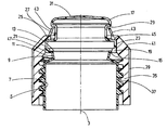
도 3은 작동 요소가 부분적으로 돌려져 조여진 시작 위치에 있는, 용기의 목부 섹션 및 헤드 섹션 영역의 확대 종단면도;
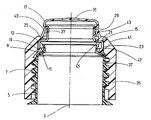
도 4는 작동 요소가 준비 위치에서 도시된 도 3에 대응하는 종단면도;
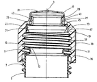
도 5는 작동 요소가 용기의 개방 후에 돌려져 조여진 위치에 도시된 도 3 및 도 4에 대응하는 단면도; 및
도 6은 개방된 용기로부터 부분적으로 열리는 위치에 있는 작동 요소가 도시된 대응하는 단면도.The present invention is described in detail below with reference to exemplary embodiments illustrated in the drawings.
Figure 1 is a perspective view schematically illustrating the natural size of an actual embodiment of an exemplary embodiment of the container of the present invention in which the open working element is in a ready position;
Fig. 2 is a view corresponding to Fig. 1 in which the actuating element is omitted;
3 is an enlarged longitudinal section of the neck section and head section area of the container, in which the actuating element is partly turned and tightened in the starting position;
Fig. 4 is a longitudinal section view corresponding to Fig. 3 in which the actuating element is shown in the ready position;
Fig. 5 is a cross-sectional view corresponding to Figs. 3 and 4 shown in a position where the actuating element is turned and twisted after opening of the container; Fig. And
6 is a corresponding cross-sectional view in which the operating element is shown in a partially open position from an open container;
도 1 및 도 2로부터 알 수 있는 바와 같이, 이러한 본 발명의 용기의 이러한 예시적인 실시예는 플라스틱 병의 형태를 하는 주 용기 섹션(1)을 가지며, 주 용기 섹션은 중앙의 주 축선(3)과 관련하여, 둥근 모서리 영역들을 구비한 정사각형 단면을 가지며, 유체를 수용하기 위한 150㎖ 충전 체적으로 디자인된다. 도 2에 가장 명확하게 도시된 바와 같이, 축선(3)에 동축인 목부 섹션(5)은 주 섹션(1)의 상부면에 몰딩되며, 이러한 목부 섹션의 지름은 대략 주 섹션(1)의 폭의 절반에 대응하고, 목부 섹션의 외측은 그 길이의 약 절반에서 수나사(7)를 구비한다. 도 3 내지 도 5에서 가장 명확히 도시된 바와 같이, 상부 영역에서, 목부 섹션(5)은 수나사(7)의 최상측 권선으로부터 짧은 축 방향 거리에 있는, 반경 방향으로 안쪽으로 진행하고 축선(3)을 향해 위로 경사진 환상 표면(9), 및 위를 향해 진행하고 축선(3)으로부터 바깥쪽으로 분기하는 단부면(11) 내로의 상단부에 있는 천이부들을 가지며, 단부면(11)의 단부 가장자리는 목부 섹션(5)의 접근 개구(13)를 에워싼다. 그러므로, 약간 바깥쪽으로 돌출하는 가장자리 융기부(15)는 접근 개구(13)의 가장자리에 형성된다. 접근 개구(13)을 위한 밀봉 섹션으로서, 헤드 섹션(17)은 목부 섹션(5)의 일체 부분으로서 상기 접근 개구(13)의 가장자리에 몰딩되고, 가장자리 융기부(15)와, 헤드 섹션(17)의 전방을 향한 단부에 위치된 보강 리브(19)는 사전 결정된 한계 지점을 형성하고, 사전 결정된 한계 지점에서, 헤드 섹션(17)은 추출 과정 동안 접근 개구(13)를 노출시키기 위하여 목부 섹션(5)으로부터 분리될 수 있다. 보강 리브(19)는 링 칼라(21)의 단부 상에서 쐐기 형상의 반경 방향으로 안쪽으로 연장하는 돌기로서 존재하며, 링 칼라의 외측은 외부 원통형 표면(23)을 형성하고, 단차 표면(25)이 외부 원통형 표면의 상단에 형성되며, 단차 표면은 상기 외부 원통형 표면(23)의 반경 방향 길이의 경계를 정하고 헤드 섹션(17)의 인접한 환상 그루브(27) 내로 반경 방향으로 안쪽으로 연장한다. 환상 그루브(27)의 상단부는 플랜지 형상 반경 방향으로 바깥을 향한 연장 돌기(29)에 의해 범위가 정해지며, 연장 돌기는 헤드 섹션(17)의 상단부 표면(31)으로 천이한다.As can be seen from Figures 1 and 2, this exemplary embodiment of this inventive container has a main container section 1 in the form of a plastic bottle, the main container section having a central,
분리 영역(15, 19)에 형성된 사전 결정된 한계 지점에서 헤드 섹션(17)을 풀기 위한 떼어냄 보조 기구로서, 슬리브 섹션(35)은 목부 섹션(5)의 수나사(7) 상으로 돌려져 조여질 수 있으며, 상기 슬리브 섹션(35)은 외측에서 원형의 원통형 길이 방향 섹션과 길이 방향 살(riffle)(39)에 있는 암나사(37)을 가진다. 경사 표면(41)은 살(39)을 가지는 원주 섹션에 인접하고, 경사 표면(41)은 상부 자유 단부면을 향하여 목부 섹션(35)의 외경을 감소시킨다. 경사 표면(41)으로부터 시작하여, 접촉 핑거(43)들이 링은 상부 단부면으로 연장하고, 접촉 핑거(43)들은 축선(3)을 향해 경사진다. 경사 표면(41)과 접촉 핑거(43)들 사이의 영역에서, 목부 섹션(43)은 반경 방향 평면에 놓인 환상 표면의 형태를 하는 내측 접촉 어깨부(45)를 형성한다.The
도 3은 슬리브 섹션이 단지 부분적으로 돌려져 조여진 시작 위치에 있는 슬리브 섹션(35)을 도시하며, 여기에서, 접촉 어깨부(45)는 링 칼라(21) 상의 단차 표면(25)으로부터 일정 거리에 위치되고, 접촉 핑거(43)들은 헤드 섹션(17)의 상단부 표면(31)으로 연장한다. 도 4는 더욱 돌려져 조여진 후에, 접촉 핑거(43)들이 돌기(29) 밑에서 헤드 섹션(17)의 환상 그루브(27) 내로 스냅 끼워맞춤된 준비 위치에 슬리브 섹션(35)이 있는 상태를 도시한다. 슬리브 섹션(35)은, 슬리브 섹션(35) 상의 경사 표면(41)의 영역에 위치된 원형의 원통형 표면(47)이 링 칼라(21)의 외부 원통형 표면(23)과 완전 접촉하도록 충분히 멀리 아래로 움직였다. 그러므로, 외부 원통형 표면(23)은 슬리브 섹션(35)을 위한 가이드 경로를 형성하고, 상기 슬리브 섹션(35)은 돌려져 조여짐에 따라서 상기 가이드 경로 상에서 그 축 방향 움직임으로 가이드된다. 도 4에 도시된 준비 위치로부터, 슬리브 섹션(35)의 접촉 표면(47)이 링 칼라(21)의 외부 원통형 표면(23)에 의해 형성된 가이드 벽에서 슬라이딩하는 도 5에 도시된 개방 위치로 슬리브 섹션이 더욱 돌려져 조여짐에 따라서, 링 칼라(21)의 단차 표면(25)을 중첩하는 슬리브 섹션(35)의 접촉 어깨부(45)는 헤드 섹션(17)을 동반하여서, 사전 결정된 한계 지점은 분리 영역(15, 17)들에서 떼어지고, 접근 개구(13)는 노출된다(이러한 상태가 예시된 도 5 참조).3 shows a
도 6은 개방 또는 떼어냄 과정 후에 도 5에 도시된 위치로부터 상기 슬리브 섹션(35)이 부분적으로 돌려져 열리는 위치에 있는 슬리브 섹션(35)을 도시한다. 이러한 축 방향 움직임 동안, 헤드 섹션(17)은 돌기(29) 상의 접촉 핑거(43)들의 언더핸드 그립에 의해 동반되어서, 슬리브 섹션(35)이 완전히 돌려져 열릴 때, 헤드 섹션(17)은 슬리브 섹션(35)과 함께 제거되고, 그러므로 제거된 슬리브 섹션(35)에 분리 불가능하게 고정된다. 병의 이어지는 폐쇄가 필요하면, 그러므로 헤드 섹션(17)은 슬리브 섹션(35)과 함께 다시 돌려져 조여지는데 사용자의 어떠한 간섭없이 이용될 수 있다. 슬리브 섹션(35)의 내부 접촉 표면(47)이 가이드 경로를 형성하는 링 칼라(21)의 외부 원통형 표면(23)과 완전히 접촉하기 때문에, 카운터 베어링은 링 칼라(21)를 위해 형성될 수 있으며, 접근 개구(13)는, 스크루 연결을 조이고 목부 섹션(5)의 환상 표면(9)에 보강 리브(19)를 접촉시키는 것에 의해 풀릴 수 있다(도 5 참조).Fig. 6 shows the
접촉 핑거(43)들이 충분히 강성인 것으로서 구성되면, 개방 과정은 또한 준비 위치(도 4)로부터 슬리브 섹션(35)을 돌려서 여는 것에 의해 수행될 수 있으며, 상향 진행하는 축 방향 움직임 동안, 돌기(29)를 구비한 언더핸드 그립에 있는 접촉 핑거(43)들은 상향 진행 전단 움직임을 위해 헤드 섹션(17)을 동반한다.If the
Claims (13)
상기 슬리브 섹션(35)은 제거 가능한 헤드 섹션(17)의 일부인 가이드 경로(23)와 적어도 부분적으로 접촉하도록 미작동 상태로부터, 상기 분리 영역(15, 19)이 풀려진 작동 상태로 가이드되는 것을 특징으로 하는 용기.(1) for receiving fluids, as well as a dispensing opening (13) for the fluid at its free end, which is connected to the container body (1) and which is made of a particularly plastic material manufactured using a blow- Wherein the dispensing opening is sealed to a head section (17) through an isolation area (15, 19), the head section actuating a movable sleeve section (35) (13) by being released from the neck section (5) by unscrewing the dispensing opening (15, 19)
Characterized in that the sleeve section (35) is guided from an unactuated state to at least partial contact with a guide path (23) which is part of the removable head section (17) As a container.
Applications Claiming Priority (5)
| Application Number | Priority Date | Filing Date | Title |
|---|---|---|---|
| DE102014016192.7A DE102014016192A1 (en) | 2014-10-31 | 2014-10-31 | container |
| DE102014016192.7 | 2014-10-31 | ||
| CN201420720014.6U CN204568328U (en) | 2014-11-26 | 2014-11-26 | Container |
| CN201420720014.6 | 2014-11-26 | ||
| PCT/EP2015/001823 WO2016066238A1 (en) | 2014-10-31 | 2015-09-10 | Container comprising a single-piece head section |
Publications (2)
| Publication Number | Publication Date |
|---|---|
| KR20170077110A true KR20170077110A (en) | 2017-07-05 |
| KR102383818B1 KR102383818B1 (en) | 2022-04-08 |
Family
ID=54106296
Family Applications (1)
| Application Number | Title | Priority Date | Filing Date |
|---|---|---|---|
| KR1020177007092A Active KR102383818B1 (en) | 2014-10-31 | 2015-09-10 | Container comprising a single-piece head section |
Country Status (14)
| Country | Link |
|---|---|
| US (1) | US10336495B2 (en) |
| EP (1) | EP3212517B1 (en) |
| JP (1) | JP6557335B2 (en) |
| KR (1) | KR102383818B1 (en) |
| AU (1) | AU2015341110B2 (en) |
| BR (1) | BR112017007514B1 (en) |
| CA (1) | CA2964285C (en) |
| ES (1) | ES2700374T3 (en) |
| MX (1) | MX380262B (en) |
| PL (1) | PL3212517T3 (en) |
| PT (1) | PT3212517T (en) |
| RU (1) | RU2692820C2 (en) |
| SG (1) | SG11201702172QA (en) |
| WO (1) | WO2016066238A1 (en) |
Families Citing this family (1)
| Publication number | Priority date | Publication date | Assignee | Title |
|---|---|---|---|---|
| USD963608S1 (en) * | 2021-01-17 | 2022-09-13 | Shenzhen Aiyinhu Technology Co., Ltd. | Gaming headset |
Citations (3)
| Publication number | Priority date | Publication date | Assignee | Title |
|---|---|---|---|---|
| US4478342A (en) * | 1983-07-14 | 1984-10-23 | Baxter Travenol Laboratories, Inc. | Sterilizable container with inner closure and collapse-resistant cover |
| US4662529A (en) * | 1985-02-28 | 1987-05-05 | Schering Chemicals Limited | Bottle with frangible neck and cap |
| EP0228662A2 (en) * | 1986-01-08 | 1987-07-15 | Abbott Laboratories | Expandable ring closure device |
Family Cites Families (7)
| Publication number | Priority date | Publication date | Assignee | Title |
|---|---|---|---|---|
| US4176755A (en) * | 1979-01-26 | 1979-12-04 | Baxter Travenol Laboratories, Inc. | Resealable pour bottle with severing ring |
| US4467930A (en) * | 1982-04-06 | 1984-08-28 | Baxter Travenol Laboratories, Inc. | Overmolded closure seal |
| US4485064A (en) * | 1982-04-06 | 1984-11-27 | Baxter Travenol Laboratories, Inc. | Antibacterial seal |
| US4494663A (en) * | 1984-01-05 | 1985-01-22 | Abbott Laboratories | Sterile solution container |
| US4721215A (en) * | 1986-01-08 | 1988-01-26 | Abbott Laboratories | Expandable ring closure device |
| CA2722551C (en) | 2008-04-25 | 2015-10-20 | Nippon Zoki Pharmaceutical Co., Ltd. | Plastic ampule |
| JP2012106773A (en) * | 2010-11-18 | 2012-06-07 | Q P Corp | Cap structure of bottle |
-
2015
- 2015-09-10 BR BR112017007514-8A patent/BR112017007514B1/en active IP Right Grant
- 2015-09-10 PT PT15763200T patent/PT3212517T/en unknown
- 2015-09-10 EP EP15763200.1A patent/EP3212517B1/en active Active
- 2015-09-10 PL PL15763200T patent/PL3212517T3/en unknown
- 2015-09-10 WO PCT/EP2015/001823 patent/WO2016066238A1/en not_active Ceased
- 2015-09-10 KR KR1020177007092A patent/KR102383818B1/en active Active
- 2015-09-10 JP JP2017522508A patent/JP6557335B2/en active Active
- 2015-09-10 AU AU2015341110A patent/AU2015341110B2/en active Active
- 2015-09-10 US US15/510,722 patent/US10336495B2/en active Active
- 2015-09-10 ES ES15763200T patent/ES2700374T3/en active Active
- 2015-09-10 RU RU2017117620A patent/RU2692820C2/en active
- 2015-09-10 SG SG11201702172QA patent/SG11201702172QA/en unknown
- 2015-09-10 CA CA2964285A patent/CA2964285C/en active Active
- 2015-09-10 MX MX2017005327A patent/MX380262B/en unknown
Patent Citations (4)
| Publication number | Priority date | Publication date | Assignee | Title |
|---|---|---|---|---|
| US4478342A (en) * | 1983-07-14 | 1984-10-23 | Baxter Travenol Laboratories, Inc. | Sterilizable container with inner closure and collapse-resistant cover |
| US4662529A (en) * | 1985-02-28 | 1987-05-05 | Schering Chemicals Limited | Bottle with frangible neck and cap |
| EP0228662A2 (en) * | 1986-01-08 | 1987-07-15 | Abbott Laboratories | Expandable ring closure device |
| JPS62168866A (en) * | 1986-01-08 | 1987-07-25 | アボツト ラボラトリ−ズ | Expansible ring cover device |
Also Published As
| Publication number | Publication date |
|---|---|
| JP6557335B2 (en) | 2019-08-07 |
| MX380262B (en) | 2025-03-12 |
| EP3212517A1 (en) | 2017-09-06 |
| RU2692820C2 (en) | 2019-06-28 |
| PT3212517T (en) | 2018-10-18 |
| CA2964285A1 (en) | 2016-05-06 |
| JP2017533152A (en) | 2017-11-09 |
| US10336495B2 (en) | 2019-07-02 |
| AU2015341110B2 (en) | 2019-08-15 |
| EP3212517B1 (en) | 2018-09-05 |
| BR112017007514A2 (en) | 2017-12-19 |
| RU2017117620A (en) | 2018-11-30 |
| SG11201702172QA (en) | 2017-04-27 |
| WO2016066238A1 (en) | 2016-05-06 |
| CA2964285C (en) | 2022-11-29 |
| AU2015341110A1 (en) | 2017-05-25 |
| KR102383818B1 (en) | 2022-04-08 |
| ES2700374T3 (en) | 2019-02-15 |
| PL3212517T3 (en) | 2019-03-29 |
| MX2017005327A (en) | 2017-08-15 |
| BR112017007514B1 (en) | 2021-10-19 |
| RU2017117620A3 (en) | 2019-01-16 |
| US20170275043A1 (en) | 2017-09-28 |
Similar Documents
| Publication | Publication Date | Title |
|---|---|---|
| KR101744846B1 (en) | Eco-friendly multi-purpose cap | |
| US20150321798A1 (en) | Container sealing device | |
| EP3543165A1 (en) | Connection structure between refill container pouring spout and package container pouring unit | |
| CN110869288B (en) | Plastic cap and method for producing same | |
| US2969161A (en) | Bung for beer barrels and the like | |
| CN114867663A (en) | Child-resistant closure and spout combination | |
| US11377271B2 (en) | Plastic closure part with severable membrane | |
| US10961025B2 (en) | Pouring spout of container | |
| JP5049823B2 (en) | cap | |
| US11299331B2 (en) | Container | |
| KR20170077110A (en) | Container comprising a single-piece head section | |
| US20210300645A1 (en) | One-piece closure for a container | |
| EP2476627A1 (en) | Nozzle arrangement fixed on a container | |
| CN106794917B (en) | Container with one-piece head | |
| CN204568328U (en) | Container | |
| HK1238617A1 (en) | Container comprising a single-piece head section | |
| JP6363036B2 (en) | Stopper cap | |
| WO2019145871A1 (en) | A capsule with a security ring | |
| US20250206507A1 (en) | Cap for a container | |
| US20190100359A1 (en) | Apparatus and method for injection moulding a cap with a tamperproof ring | |
| HK1238617B (en) | Container comprising a single-piece head section | |
| US20180186519A1 (en) | Caps and adapters for containers | |
| JP2023114600A (en) | Cap having virgin seal function and attachable to container mouth by screwing-in | |
| JP2009001333A (en) | Recycle encouraging liquid container with stopper cap opening/closing function and stopper cap | |
| JP5011165B2 (en) | cap |
Legal Events
| Date | Code | Title | Description |
|---|---|---|---|
| PA0105 | International application |
St.27 status event code: A-0-1-A10-A15-nap-PA0105 |
|
| PG1501 | Laying open of application |
St.27 status event code: A-1-1-Q10-Q12-nap-PG1501 |
|
| A201 | Request for examination | ||
| P11-X000 | Amendment of application requested |
St.27 status event code: A-2-2-P10-P11-nap-X000 |
|
| P13-X000 | Application amended |
St.27 status event code: A-2-2-P10-P13-nap-X000 |
|
| PA0201 | Request for examination |
St.27 status event code: A-1-2-D10-D11-exm-PA0201 |
|
| E902 | Notification of reason for refusal | ||
| PE0902 | Notice of grounds for rejection |
St.27 status event code: A-1-2-D10-D21-exm-PE0902 |
|
| E13-X000 | Pre-grant limitation requested |
St.27 status event code: A-2-3-E10-E13-lim-X000 |
|
| P11-X000 | Amendment of application requested |
St.27 status event code: A-2-2-P10-P11-nap-X000 |
|
| P13-X000 | Application amended |
St.27 status event code: A-2-2-P10-P13-nap-X000 |
|
| E701 | Decision to grant or registration of patent right | ||
| PE0701 | Decision of registration |
St.27 status event code: A-1-2-D10-D22-exm-PE0701 |
|
| GRNT | Written decision to grant | ||
| PR0701 | Registration of establishment |
St.27 status event code: A-2-4-F10-F11-exm-PR0701 |
|
| PR1002 | Payment of registration fee |
St.27 status event code: A-2-2-U10-U12-oth-PR1002 Fee payment year number: 1 |
|
| PG1601 | Publication of registration |
St.27 status event code: A-4-4-Q10-Q13-nap-PG1601 |
|
| PR1001 | Payment of annual fee |
St.27 status event code: A-4-4-U10-U11-oth-PR1001 Fee payment year number: 4 |
|
| PR1001 | Payment of annual fee |
St.27 status event code: A-4-4-U10-U11-oth-PR1001 Fee payment year number: 5 |
|
| U11 | Full renewal or maintenance fee paid |
Free format text: ST27 STATUS EVENT CODE: A-4-4-U10-U11-OTH-PR1001 (AS PROVIDED BY THE NATIONAL OFFICE) Year of fee payment: 5 |