KR20170077126A - Industrial running vehicle - Google Patents
Industrial running vehicle Download PDFInfo
- Publication number
- KR20170077126A KR20170077126A KR1020177010696A KR20177010696A KR20170077126A KR 20170077126 A KR20170077126 A KR 20170077126A KR 1020177010696 A KR1020177010696 A KR 1020177010696A KR 20177010696 A KR20177010696 A KR 20177010696A KR 20170077126 A KR20170077126 A KR 20170077126A
- Authority
- KR
- South Korea
- Prior art keywords
- display
- screen
- camera image
- display screen
- liquid crystal
- Prior art date
- Legal status (The legal status is an assumption and is not a legal conclusion. Google has not performed a legal analysis and makes no representation as to the accuracy of the status listed.)
- Granted
Links
Images















Classifications
-
- B—PERFORMING OPERATIONS; TRANSPORTING
- B60—VEHICLES IN GENERAL
- B60K—ARRANGEMENT OR MOUNTING OF PROPULSION UNITS OR OF TRANSMISSIONS IN VEHICLES; ARRANGEMENT OR MOUNTING OF PLURAL DIVERSE PRIME-MOVERS IN VEHICLES; AUXILIARY DRIVES FOR VEHICLES; INSTRUMENTATION OR DASHBOARDS FOR VEHICLES; ARRANGEMENTS IN CONNECTION WITH COOLING, AIR INTAKE, GAS EXHAUST OR FUEL SUPPLY OF PROPULSION UNITS IN VEHICLES
- B60K35/00—Instruments specially adapted for vehicles; Arrangement of instruments in or on vehicles
-
- B—PERFORMING OPERATIONS; TRANSPORTING
- B60—VEHICLES IN GENERAL
- B60K—ARRANGEMENT OR MOUNTING OF PROPULSION UNITS OR OF TRANSMISSIONS IN VEHICLES; ARRANGEMENT OR MOUNTING OF PLURAL DIVERSE PRIME-MOVERS IN VEHICLES; AUXILIARY DRIVES FOR VEHICLES; INSTRUMENTATION OR DASHBOARDS FOR VEHICLES; ARRANGEMENTS IN CONNECTION WITH COOLING, AIR INTAKE, GAS EXHAUST OR FUEL SUPPLY OF PROPULSION UNITS IN VEHICLES
- B60K35/00—Instruments specially adapted for vehicles; Arrangement of instruments in or on vehicles
- B60K35/80—Arrangements for controlling instruments
- B60K35/81—Arrangements for controlling instruments for controlling displays
-
- B—PERFORMING OPERATIONS; TRANSPORTING
- B60—VEHICLES IN GENERAL
- B60K—ARRANGEMENT OR MOUNTING OF PROPULSION UNITS OR OF TRANSMISSIONS IN VEHICLES; ARRANGEMENT OR MOUNTING OF PLURAL DIVERSE PRIME-MOVERS IN VEHICLES; AUXILIARY DRIVES FOR VEHICLES; INSTRUMENTATION OR DASHBOARDS FOR VEHICLES; ARRANGEMENTS IN CONNECTION WITH COOLING, AIR INTAKE, GAS EXHAUST OR FUEL SUPPLY OF PROPULSION UNITS IN VEHICLES
- B60K35/00—Instruments specially adapted for vehicles; Arrangement of instruments in or on vehicles
- B60K35/10—Input arrangements, i.e. from user to vehicle, associated with vehicle functions or specially adapted therefor
-
- B—PERFORMING OPERATIONS; TRANSPORTING
- B60—VEHICLES IN GENERAL
- B60K—ARRANGEMENT OR MOUNTING OF PROPULSION UNITS OR OF TRANSMISSIONS IN VEHICLES; ARRANGEMENT OR MOUNTING OF PLURAL DIVERSE PRIME-MOVERS IN VEHICLES; AUXILIARY DRIVES FOR VEHICLES; INSTRUMENTATION OR DASHBOARDS FOR VEHICLES; ARRANGEMENTS IN CONNECTION WITH COOLING, AIR INTAKE, GAS EXHAUST OR FUEL SUPPLY OF PROPULSION UNITS IN VEHICLES
- B60K35/00—Instruments specially adapted for vehicles; Arrangement of instruments in or on vehicles
- B60K35/20—Output arrangements, i.e. from vehicle to user, associated with vehicle functions or specially adapted therefor
- B60K35/21—Output arrangements, i.e. from vehicle to user, associated with vehicle functions or specially adapted therefor using visual output, e.g. blinking lights or matrix displays
- B60K35/22—Display screens
-
- B—PERFORMING OPERATIONS; TRANSPORTING
- B60—VEHICLES IN GENERAL
- B60K—ARRANGEMENT OR MOUNTING OF PROPULSION UNITS OR OF TRANSMISSIONS IN VEHICLES; ARRANGEMENT OR MOUNTING OF PLURAL DIVERSE PRIME-MOVERS IN VEHICLES; AUXILIARY DRIVES FOR VEHICLES; INSTRUMENTATION OR DASHBOARDS FOR VEHICLES; ARRANGEMENTS IN CONNECTION WITH COOLING, AIR INTAKE, GAS EXHAUST OR FUEL SUPPLY OF PROPULSION UNITS IN VEHICLES
- B60K35/00—Instruments specially adapted for vehicles; Arrangement of instruments in or on vehicles
- B60K35/20—Output arrangements, i.e. from vehicle to user, associated with vehicle functions or specially adapted therefor
- B60K35/28—Output arrangements, i.e. from vehicle to user, associated with vehicle functions or specially adapted therefor characterised by the type of the output information, e.g. video entertainment or vehicle dynamics information; characterised by the purpose of the output information, e.g. for attracting the attention of the driver
-
- B—PERFORMING OPERATIONS; TRANSPORTING
- B60—VEHICLES IN GENERAL
- B60K—ARRANGEMENT OR MOUNTING OF PROPULSION UNITS OR OF TRANSMISSIONS IN VEHICLES; ARRANGEMENT OR MOUNTING OF PLURAL DIVERSE PRIME-MOVERS IN VEHICLES; AUXILIARY DRIVES FOR VEHICLES; INSTRUMENTATION OR DASHBOARDS FOR VEHICLES; ARRANGEMENTS IN CONNECTION WITH COOLING, AIR INTAKE, GAS EXHAUST OR FUEL SUPPLY OF PROPULSION UNITS IN VEHICLES
- B60K35/00—Instruments specially adapted for vehicles; Arrangement of instruments in or on vehicles
- B60K35/20—Output arrangements, i.e. from vehicle to user, associated with vehicle functions or specially adapted therefor
- B60K35/29—Instruments characterised by the way in which information is handled, e.g. showing information on plural displays or prioritising information according to driving conditions
-
- B60K37/06—
-
- G—PHYSICS
- G09—EDUCATION; CRYPTOGRAPHY; DISPLAY; ADVERTISING; SEALS
- G09G—ARRANGEMENTS OR CIRCUITS FOR CONTROL OF INDICATING DEVICES USING STATIC MEANS TO PRESENT VARIABLE INFORMATION
- G09G5/00—Control arrangements or circuits for visual indicators common to cathode-ray tube indicators and other visual indicators
-
- G—PHYSICS
- G09—EDUCATION; CRYPTOGRAPHY; DISPLAY; ADVERTISING; SEALS
- G09G—ARRANGEMENTS OR CIRCUITS FOR CONTROL OF INDICATING DEVICES USING STATIC MEANS TO PRESENT VARIABLE INFORMATION
- G09G5/00—Control arrangements or circuits for visual indicators common to cathode-ray tube indicators and other visual indicators
- G09G5/36—Control arrangements or circuits for visual indicators common to cathode-ray tube indicators and other visual indicators characterised by the display of a graphic pattern, e.g. using an all-points-addressable [APA] memory
-
- G—PHYSICS
- G09—EDUCATION; CRYPTOGRAPHY; DISPLAY; ADVERTISING; SEALS
- G09G—ARRANGEMENTS OR CIRCUITS FOR CONTROL OF INDICATING DEVICES USING STATIC MEANS TO PRESENT VARIABLE INFORMATION
- G09G5/00—Control arrangements or circuits for visual indicators common to cathode-ray tube indicators and other visual indicators
- G09G5/36—Control arrangements or circuits for visual indicators common to cathode-ray tube indicators and other visual indicators characterised by the display of a graphic pattern, e.g. using an all-points-addressable [APA] memory
- G09G5/37—Details of the operation on graphic patterns
- G09G5/377—Details of the operation on graphic patterns for mixing or overlaying two or more graphic patterns
-
- B60K2350/2013—
-
- B60K2350/352—
-
- B—PERFORMING OPERATIONS; TRANSPORTING
- B60—VEHICLES IN GENERAL
- B60Y—INDEXING SCHEME RELATING TO ASPECTS CROSS-CUTTING VEHICLE TECHNOLOGY
- B60Y2200/00—Type of vehicle
- B60Y2200/20—Off-Road Vehicles
- B60Y2200/22—Agricultural vehicles
Landscapes
- Engineering & Computer Science (AREA)
- Chemical & Material Sciences (AREA)
- Combustion & Propulsion (AREA)
- Transportation (AREA)
- Mechanical Engineering (AREA)
- Physics & Mathematics (AREA)
- Computer Hardware Design (AREA)
- General Physics & Mathematics (AREA)
- Theoretical Computer Science (AREA)
- Harvester Elements (AREA)
- Combines (AREA)
- Control Of Indicators Other Than Cathode Ray Tubes (AREA)
Abstract
과제는, 기본 정보의 결여에 의해서 작업에 지장을 초래하는 불편을 해소하는 것이다. 해결 수단은, 액정 표시부(14)와, 상기 액정 표시부(14)의 표시를 제어하는 표시 제어부(24)를 구비하는 콤바인(1)으로서, 표시 제어부(24)는, 액정 표시부(14)의 표시 화면을, 인위적인 화면 전환 조작에 따라서, 통상 표시 화면(14(A))로부터, 카메라 화상(d)을 표시하는 카메라 화상 표시 화면(14(C))으로의 전환에 있어서, 통상 표시 화면(14(A))의 표시 정보를, 중요도가 높은 기본 정보군(a)과, 상기 기본 정보군(a)보다 중요도가 낮은 부속 정보군(b)으로 나누어서 표시함과 함께, 카메라 화상 표시 화면(14(C))으로의 전환시에, 기본 정보군(a)의 표시를 유지하면서, 부속 정보군(b) 대신에 카메라 화상(d)을 표시시키는 것이다.The task is to eliminate inconveniences that cause work troubles due to lack of basic information. The solving means is a combine 1 having a liquid crystal display section 14 and a display control section 24 for controlling the display of the liquid crystal display section 14. The display control section 24 controls the display of the liquid crystal display section 14, In the switching from the normal display screen 14 (A) to the camera image display screen 14 (C) for displaying the camera image d in accordance with the artificial screen switching operation, (A) is divided into a basic information group (a) having high importance and a subsidiary information group (b) having lower importance than the basic information group (a) (D) in place of the accessory information group (b), while maintaining the display of the basic information group (a).

Description
본 발명은, 액정 표시부를 구비하는 콤바인 등의 작업용 주행차에 관한 것이다. BACKGROUND OF THE
액정 표시부를 구비하는 작업용 주행차가 알려져 있다. 예를 들면, 특허문헌 1에 나타나는 작업용 주행차는, 복수 종류의 화면에 대응한 복수의 터치 조작 버튼을 터치 패널식의 액정 표시부에 표시시킴과 함께, 터치 조작 버튼의 터치 조작에 따라서 대응하는 화면을 액정 표시부에 표시시키도록 구성되어 있다. 이러한 액정 표시부를 구비하는 작업용 주행차에서는, 액정 표시부를 이용하여 각종 상태 표시나 설정 조작을 행할 수 있으므로, 개별의 표시부(미터(meter) 등)나 설정 도구를 마련하는 경우에 비해, 부품 수를 삭감 가능할 뿐만 아니라, 상태 확인이나 설정 조작이 용이하게 된다고 하는 이점이 있다. A traveling vehicle for work having a liquid crystal display part is known. For example, the working vehicle shown in
그러나, 이러한 작업용 주행차에서는, 액정 표시부의 화면을 전환하면, 중요도가 높은 정보를 확인할 수 없게 되고, 작업에 지장을 초래할 우려가 있었다. 예를 들면, 액정 표시부의 표시 화면을, 인위적인 화면 전환 조작에 따라서, 통상 표시 화면으로부터, 카메라 화상을 표시하는 카메라 화상 표시 화면으로 전환하면, 엔진 회전, 엔진 부하, 차속(車速) 등의 기본 정보를 확인할 수 없게 될 우려가 있었다. However, in such a traveling vehicle for work, if the screen of the liquid crystal display part is switched, information with high importance can not be confirmed, and there is a fear that the operation will be hindered. For example, when the display screen of the liquid crystal display section is switched from a normal display screen to a camera image display screen for displaying a camera image in accordance with an artificial screen switching operation, basic information such as engine rotation, engine load, vehicle speed There is a possibility that it can not be confirmed.
본 발명은, 상기와 같은 실정에 비추어서 이들의 과제를 해결하는 것을 목적으로 하여 창작된 것으로서, 액정 표시부와, 상기 액정 표시부의 표시를 제어하는 표시 제어부를 구비하는 작업용 주행차로서, 상기 표시 제어부는 상기 액정 표시부의 표시 화면을 인위적인 화면 전환 조작에 따라서 통상 표시 화면으로부터 카메라 화상을 표시하는 카메라 화상 표시 화면으로의 전환에 있어서, 상기 통상 표시 화면의 표시 정보를 중요도가 높은 기본 정보군과 상기 기본 정보군보다 중요도가 낮은 부속 정보군으로 나누어서 표시함과 함께, 상기 카메라 화상 표시 화면으로의 전환시에 기본 정보군의 표시를 유지하면서 부속 정보군 대신에 카메라 화상을 표시시키는 것을 특징으로 한다. The present invention is directed to a working vehicle comprising a liquid crystal display section and a display control section for controlling display of the liquid crystal display section, the display control section being created for the purpose of solving these problems in view of the above- In switching from a normal display screen to a camera image display screen for displaying a camera image in accordance with an artificial screen switching operation, the display information of the normal display screen is divided into a basic information group having high importance and a basic information group And displays the camera image instead of the accessory information group while maintaining the display of the basic information group at the time of switching to the camera image display screen.
또한, 청구항 2의 발명은, 청구항 1에 기재된 작업용 주행차로서, 상기 표시 제어부는 상기 액정 표시부의 표시 화면을 인위적인 화면 전환 조작에 따라서 기본 정보군을 확대 표시하는 기본 정보군 확대 표시 화면으로 전환 가능한 것을 특징으로 한다. According to a second aspect of the present invention, there is provided a running vehicle according to the first aspect, wherein the display control section switches the display screen of the liquid crystal display section to a basic information group enlarged display screen for enlarging and displaying the basic information group according to an artificial screen switching operation .
또한, 청구항 3의 발명은, 청구항 1 또는 2에 기재된 작업용 주행차로서, 상기 표시 제어부는 상기 액정 표시부의 표시 화면을 인위적인 화면 전환 조작에 따라서 상기 카메라 화상 표시 화면으로부터 다른 카메라 화상을 표시하는 제2의 카메라 화상 표시 화면으로 전환 가능하고 상기 제2의 카메라 화상 표시 화면에서는 기본 정보군의 표시를 유지하면서 카메라 화상을 다른 카메라 화상으로 전환하는 것을 특징으로 한다. According to a third aspect of the present invention, there is provided a running vehicle according to the first or second aspect, wherein the display control section controls the display screen of the liquid crystal display section to display a second camera image from the camera image display screen in accordance with an artificial screen switching operation And the second camera image display screen switches the camera image to another camera image while maintaining the display of the basic information group.
또한, 청구항 4의 발명은, 청구항 1 ~ 3의 어느 한 항에 기재된 작업용 주행차로서, 상기 표시 제어부는 상기 액정 표시부의 표시 화면을 인위적인 화면 전환 조작에 따라서 상기 카메라 화상 표시 화면으로부터 카메라 화상을 확대 표시하는 카메라 화상 확대 표시 화면으로 전환 가능하고, 상기 카메라 화상 확대 표시 화면에서는 기본 정보군의 표시 영역을 축소 또는 생략하여 카메라 화상을 확대 표시시키는 것을 특징으로 한다. According to a fourth aspect of the present invention, there is provided a running vehicle according to any one of the first to third aspects, wherein the display control section enlarges the display image of the liquid crystal display section from the camera image display screen in accordance with an artificial screen switching operation And the camera image enlargement display screen is displayed by enlarging or reducing the camera image by reducing or omitting the display area of the basic information group on the camera image enlargement display screen.
또한, 청구항 5의 발명은, 청구항 1 ~ 4의 어느 한 항에 기재된 작업용 주행차로서, 상기 표시 제어부는 키 스위치가 ON 조작되었을 때, 이전회의 작업에서 마지막에 표시된 표시 화면을 상기 액정 표시부에 표시시키는 것을 특징으로 한다. According to a fifth aspect of the invention, there is provided a running vehicle according to any one of the first to fourth aspects, wherein when the key switch is turned on, the display control unit displays the last displayed display screen in the previous meeting on the liquid crystal display unit .
또한, 청구항 6의 발명은, 청구항 1 ~ 5의 어느 한 항에 기재된 작업용 주행차로서, 상기 액정 표시부가 터치 패널식이며, 상기 표시 제어부는 상기 액정 표시부의 터치 조작에 따라서 상기 액정 표시부의 표시 화면을 전환하는 것을 특징으로 한다. According to a sixth aspect of the invention, there is provided a working vehicle according to any one of the first to fifth aspects, wherein the liquid crystal display part is of a touch panel type, and the display control part controls the display screen of the liquid crystal display part in accordance with a touch operation of the liquid crystal display part .
청구항 1의 발명에 의하면, 카메라 화상 표시 화면으로의 전환시에, 기본 정보군의 표시를 유지하면서 부속 정보군 대신에 카메라 화상을 표시시키므로, 카메라 화상 표시 화면으로의 전환 후에도, 기본 정보를 용이하게 확인할 수 있고, 그 결과 기본 정보의 결여에 의해서 작업에 지장을 초래하는 불편을 해소할 수 있다. According to the invention of
또한, 청구항 2의 발명에 의하면, 필요에 따라서 기본 정보군을 확대 표시할 수 있으므로, 예를 들면 부속 정보를 필요로 하지 않는 비작업 주행시에 기본 정보의 시인성을 향상시킬 수 있다. According to the invention of
또한, 청구항 3의 발명에 의하면, 카메라 화상 표시 화면에 있어서, 기본 정보군의 표시를 유지하면서 카메라 화상을 다른 카메라 화상으로 전환할 수 있으므로, 예를 들면, 기체(機體) 후방을 촬영하는 안전 확인용의 백 카메라 화상과, 오거(auger) 배출구에 장착된 배출 위치 조정용의 오거 카메라 화상을 필요에 따라서 전환 표시하는 것이 가능하게 된다. According to the invention of
또한, 청구항 4의 발명에 의하면, 필요에 따라서 카메라 화상을 확대 표시할 수 있으므로, 예를 들면 백 카메라 화상을 확대시켜서 안전 확인을 용이하게 하거나, 오거 카메라 화상을 확대시켜서 배출 위치 조정의 정밀도를 높일 수 있다. According to the invention of
또한, 청구항 5의 발명에 의하면, 키 스위치가 ON 조작되었을 때, 이전회의 작업에서 마지막에 표시한 표시 화면을 액정 표시부에 표시시키므로, 키 스위치의 ON 조작 후 일일이 원하는 표시 화면으로 전환하는 수고가 불필요해진다. According to the fifth aspect of the present invention, when the key switch is turned on, the display screen displayed last in the previous meeting operation is displayed on the liquid crystal display unit, so that it is unnecessary to switch to a desired display screen after the ON operation of the key switch It becomes.
또한, 청구항 6의 발명에 의하면, 액정 표시부의 터치 조작에 따라서 액정 표시부의 표시 화면을 전환하므로, 물리적 조작 버튼의 개수를 삭감할 수 있다. According to the invention of
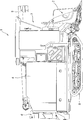
도 1은 콤바인의 좌측면도이다.
도 2는 콤바인의 우측면도이다.
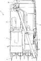
도 3은 콤바인의 평면도이다.
도 4는 콤바인의 정면도이다.
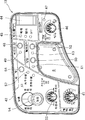
도 5는 조종부의 평면도이다.
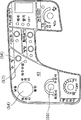
도 6은 조종부의 사이드 패널을 나타내는 평면도이다.
도 7은 설정 조작 패널의 평면도이다.
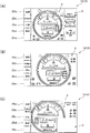
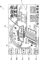
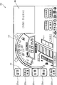
도 8은 액정 표시부의 표시 화면을 나타내는 설명도이며, (A)는 통상 표시 화면의 설명도, (B)는 심플 표시 화면의 설명도, (C)는 카메라 화상 표시 화면의 설명도이다.
도 9는 통상 작업 모드에 있어서의 화면 천이를 나타내는 설명도이다.
도 10은 메인테넌스 모드에 있어서의 화면 천이를 나타내는 설명도이다.
도 11은 메인테넌스 모드에 있어서의 유저용 메인테넌스 화면의 천이를 나타내는 설명도이다.
도 12는 메인테넌스 모드에 있어서의 딜러용 메인테넌스 화면의 천이를 나타내는 설명도이다.
도 13은 표시 제어부의 입출력을 나타내는 블럭도이다.
도 14는 표시 제어부의 모드 이행을 나타내는 플로우차트이다.
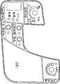
도 15는 조종부의 평면도이다.
도 16은 수지 시트의 평면도이다.
도 17은 수지 시트의 제2 패턴을 나타내는 평면도이다.
도 18은 수지 시트의 제3 패턴을 나타내는 평면도이다.
도 19는 수지 시트의 제4 패턴을 나타내는 평면도이다.
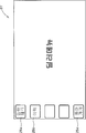
도 20은 상세 표시 화면의 설명도이다.
도 21은 심플 표시 화면의 설명도이다.
도 22는 카메라 화상 표시 화면의 설명도이다.
도 23은 카메라 화상 확대 표시 화면의 설명도이다.
도 24는 설정 화면의 설명도이다.
도 25는 버튼 조작이나 플릭(flick) 조작(스와이프 조작)에 의한 화면 천이를 나타내는 설명도이다.
도 26은 확대 조작(탭 조작)에 의한 화면 천이를 나타내는 설명도이다.
도 27은 이상 표시 화면(경보 항목)의 설명도이다.
도 28은 이상 표시 화면(엔진 정지 항목)의 설명도이다.
도 29는 설정 화면과 딜러 메뉴 초기 화면과의 사이의 전환을 나타내는 설명도이다.
도 30은 딜러 메뉴 초기 화면의 설명도이다.
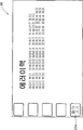
도 31은 에러 이력 표시 화면의 설명도이다.
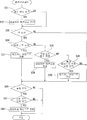
도 32는 초기 표시 제어를 나타내는 플로우차트이다.
도 33은 화면 표시 전환 제어를 나타내는 플로우차트이다.
도 34는 이상 통지 제어를 나타내는 플로우차트이다.
도 35는 에러 이력 표시 제어를 나타내는 플로우차트이다. 1 is a left side view of the combine.
2 is a right side view of the combine.
3 is a plan view of the combine.
4 is a front view of the combine.
5 is a plan view of the steering unit.
6 is a plan view showing the side panel of the control section.
7 is a plan view of the setting operation panel.
Fig. 8 is an explanatory view showing a display screen of the liquid crystal display part, Fig. 8A is an explanatory diagram of a normal display screen, Fig. 8B is an explanatory diagram of a simple display screen, and Fig.
Fig. 9 is an explanatory view showing a screen transition in the normal operation mode. Fig.
Fig. 10 is an explanatory diagram showing a screen transition in the maintenance mode. Fig.
Fig. 11 is an explanatory diagram showing the transition of the maintenance main screen for the user in the maintenance mode. Fig.
Fig. 12 is an explanatory view showing the transition of the dealer maintenance screen in the maintenance mode. Fig.
13 is a block diagram showing the input / output of the display control unit.
14 is a flowchart showing the mode transition of the display control section.
15 is a plan view of the control portion.
16 is a plan view of the resin sheet.
17 is a plan view showing a second pattern of the resin sheet.
18 is a plan view showing a third pattern of the resin sheet.
19 is a plan view showing a fourth pattern of the resin sheet.
20 is an explanatory diagram of a detailed display screen;
21 is an explanatory diagram of a simple display screen.
22 is an explanatory diagram of a camera image display screen.
23 is an explanatory diagram of a camera image enlargement display screen.
24 is an explanatory diagram of a setting screen.
Fig. 25 is an explanatory view showing a screen transition by a button operation or a flick operation (swipe operation).
Fig. 26 is an explanatory view showing a screen transition by an enlargement operation (tap operation).
27 is an explanatory diagram of an abnormal display screen (alarm item).
28 is an explanatory diagram of an abnormality display screen (engine stop item).
FIG. 29 is an explanatory view showing switching between a setting screen and a dealer menu initial screen. FIG.
30 is an explanatory diagram of the dealer menu initial screen.
31 is an explanatory diagram of an error history display screen.
32 is a flowchart showing initial display control.
Fig. 33 is a flowchart showing screen display switching control.
34 is a flowchart showing abnormality notification control.
35 is a flowchart showing error history display control.
이하, 본 발명의 실시형태에 대해서, 도면에 기초하여 설명한다. 도 1 ~ 도 4에 있어서, 1은 작업용 주행차인 콤바인으로서, 상기 콤바인(1)은, 줄기를 예취(刈取)하는 전처리부(前處理部)(2)와, 줄기로부터 곡물을 탈곡하여 선별하는 탈곡부(3)와, 선별한 곡물을 저장하는 곡물 탱크(4)와, 곡물 탱크(4) 내의 곡물을 기외(機外)로 반출하는 오거(auger)(5)와, 탈곡 완료된 짚을 후처리하는 후처리부(後處理部)(6)와, 오퍼레이터가 승차하는 조종부(7)와, 크롤러(crawler)식의 주행부(8)를 구비하여 구성되어 있다. Hereinafter, embodiments of the present invention will be described with reference to the drawings. 1 to 4,
도 5에 나타내는 바와 같이, 조종부(7)에는, 오퍼레이터가 앉는 운전석(9)이 마련됨과 함께, 그 근방에는, 멀티 스티어링 레버(38), 주 변속 레버(62), 부 변속 레버(63), 설정 조작 패널(13), 액정 표시부(14) 등이 배치되어 있다. 5, a
멀티 스티어링 레버(38)는, 운전석(9)의 전방 우측에 배치되는 조이스틱형의 조작 레버이며, 그 전후 방향의 조작에 기초하여 전처리부(2)를 승강시키는 전처리 승강 조작 도구와, 그 좌우 방향의 조작에 기초하여 기체의 방향을 변화시키는 조향 조작 도구로 겸용되고 있고, 주로 오퍼레이터의 오른손으로 조작된다. The
주 변속 레버(62) 및 부 변속 레버(63)는, 운전석(9)의 좌측방에 배치되어 있다. 한쪽의 주 변속 레버(62)는, 주행 속도를 무단 변속하는 무단 변속 조작 도구와, 전후진을 전환하는 전후진 전환 조작 도구를 겸하고 있고, 주로 오퍼레이터의 왼손으로 조작된다. 또한, 다른쪽의 부 변속 레버(63)는, 주 변속 레버(62)에 의한 변속 레인지를 단계적으로 전환하는 유단 변속 조작 도구이며, 주로 오퍼레이터의 왼손으로 조작된다. The main
도 5 ~ 도 7에 나타내는 바와 같이, 설정 조작 패널(13)은, 운전석(9)의 전방 좌측에 배치되어 있고, 여기에 각종 설정 조작 도구가 집중적으로 배치되어 있다. 그리고, 이들의 설정 조작 도구는, 주로 오퍼레이터의 왼손으로 조작된다. 또한, 설정 조작 패널(13)에 마련되는 설정 조작 도구 및 그 배치에 대해서는 후술한다. As shown in Figs. 5 to 7, the setting
액정 표시부(14)는, 액정 패널(14a)에 터치 패널(14b)을 적층시킨 터치 패널식의 액정 디스플레이이며, 운전석(9)의 전방 좌우 중앙부에 배치되어 있다. 구체적으로 설명하면, 본 실시형태의 액정 표시부(14)는, 오퍼레이터의 오른손으로 조작되는 멀티 스티어링 레버(38)의 좌측방에 배치되어 있고, 주로 오퍼레이터의 왼손으로 터치 조작된다. The liquid
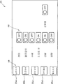
액정 표시부(14)는, 마이크로컴퓨터 등을 이용하여 구성되는 표시 제어부(24)(도 13 참조)에 접속되고, 상기 표시 제어부(24)에 의해 표시 제어된다. 도 8에 나타내는 바와 같이, 표시 제어부(24)는, 액정 표시부(14)의 표시 내용을 전환 조작 가능한 복수의 터치 조작 버튼(25a ~ 25e)을 액정 표시부(14)에 표시시키는 것에 있어서, 액정 표시부(14)의 좌우 단부 중, 멀티 스티어링 레버(38)와는 반대측의 단부, 즉, 좌측의 단부에 복수의 터치 조작 버튼(25a ~ 25e)을 세로 배열 형상으로 표시시킨다. 이와 같이 하면, 주행 중에 오른손으로 멀티 스티어링 레버(38)를 조작하면서, 왼손으로 액정 표시부(14)의 터치 조작 버튼(25a ~ 25e)을 터치 조작 가능할 뿐만 아니라, 이 때, 터치 조작하는 손이 액정 표시부(14)의 표시 화면을 가리는 것을 회피하여, 액정 표시부(14)의 시인성도 향상시킬 수 있다. The liquid
또한, 본 실시형태에서는, 액정 표시부(14)의 인접 위치에, 복수의 터치 조작 버튼(25a ~ 25e)과 병렬 형상으로 인접하는 복수의 물리적 조작 버튼(26a ~ 26e)을 배치하고 있다. 구체적으로는, 액정 표시부(14)의 좌측의 인접 위치에, 복수의 물리적 조작 버튼(26a ~ 26e)을 세로 배열 형상으로 배치하고 있다. 그리고, 표시 제어부(24)는, 물리적 조작 버튼(26a ~ 26e)이 조작되었을 때, 상기 조작된 물리적 조작 버튼(26a ~ 26e)에 인접하는 터치 조작 버튼(25a ~ 25e)이 터치 조작되었을 경우와 마찬가지로 액정 표시부(14)의 표시 내용을 전환한다. 이와 같이 하면, 액정 표시부(14)의 터치 기능에 문제가 생기고 있는 상황이나, 오염이나 장갑에 의해서 터치 조작이 불가능한 상황에 있어서도, 표시 내용의 전환 조작이 허용되고, 필요한 정보를 취득하는 것이 가능하게 된다. In the present embodiment, a plurality of
또한, 본 실시형태에서는, 상술한 바와 같이, 액정 표시부(14)의 좌우 측방 중, 멀티 스티어링 레버(38)와는 반대측의 측방인 좌측방에 복수의 설정 조작 도구(설정 조작 패널(13))를 집중 배치하고 있다. 이와 같이 하면, 주행 중에 오른손으로 멀티 스티어링 레버(38)를 조작하면서, 왼손으로 설정 조작 패널(13)에 마련되는 복수의 설정 조작 도구를 조작 가능할 뿐만 아니라, 이 때, 설정 조작 도구를 조작하는 손이 액정 표시부(14)의 표시 화면을 가리는 것을 회피하여, 액정 표시부(14)의 시인성도 향상시킬 수 있다. In the present embodiment, as described above, a plurality of setting operation tools (setting operation panel 13) are provided on the left side of the left and right sides of the liquid
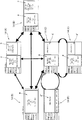
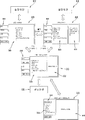
표시 제어부(24)는, 액정 표시부(14)의 표시 모드로서, 통상 작업시에 사용되는 통상 작업 모드(통상 작업 화면)와, 메인테넌스시에 사용되는 메인테넌스 모드(메인테넌스 화면)를 출현시킨다. 우선, 통상 작업 모드에 있어서 표시 가능한 화면 및 그 천이에 대해서, 도 8 및 도 9를 참조하여 설명한다. The
표시 제어부(24)는, 통상 작업 모드에 있어서, 액정 표시부(14)의 표시 화면을, 터치 조작 버튼(25a ~ 25e) 또는 물리적 조작 버튼(26a ~ 26e)에 의한 화면 전환 조작(이하, 적절하며 인위적인 화면 전환 조작이라고 한다.)에 따라서, 디폴트 표시 화면인 통상 표시 화면(A)으로부터, 각종 설정 정보를 표시하는 설정 정보 표시 화면(B)과, 카메라 화상을 표시하는 카메라 화상 표시 화면(C)과, 후술하는 심플 표시 화면(D)으로 전환한다. The
또한, 터치 조작 버튼(25a ~ 25e)에는, 전환 가능한 화면의 명칭을 표시하고, 그 터치 조작 또는 인접하는 물리적 조작 버튼(26a ~ 26e)의 조작에 따라서, 대응하는 화면으로의 전환을 실행함과 함께, 표시 중의 화면에 대응하는 터치 조작 버튼(25a ~ 25e)의 표시색을 변화시키고, 현재의 표시 화면을 인식 가능하게 하고 있다. The
통상 표시 화면(A)의 표시 정보에는, 중요도가 높은 기본 정보군(a)과, 상기 기본 정보군(a)보다 중요도가 낮은 부속 정보군(b)이 포함되어 있고, 본 실시형태에서는, 기본 정보군(a)과 부속 정보군(b)을 액정 표시부(14)의 좌우의 표시 영역으로 나누어서 표시한다. 예를 들면, 본 실시형태의 기본 정보군(a)에는, 방향·작업등 정보, 엔진 회전 정보, 엔진 부하율 정보, 차속(車速) 정보, 연료 정보, 탱크 미탈곡벼(unhulled rice)량 정보 등이 포함되고, 부속 정보군(b)에는, 선별 부하 정보, 당기(唐箕) 풍량 정보, 기체의 기울기 정보, 채프시이브(chaff sieve) 개도(開度) 정보 등이 포함되어 있다. The display information of the normal display screen A includes the basic information group a having a high degree of importance and the auxiliary information group b having a lower importance level than the basic information group a, The information group (a) and the subsidiary information group (b) are divided into the left and right display regions of the liquid
표시 제어부(24)는, 통상 표시 화면(A)으로부터 설정 정보 표시 화면(B) 또는 카메라 화상 표시 화면(C)으로의 전환시에, 기본 정보군(a)의 표시를 유지하면서, 부속 정보군(b) 대신에 각종 설정 정보(c) 또는 카메라 화상(d)을 표시시킨다. 이와 같이 하면, 설정 정보 표시 화면(B) 또는 카메라 화상 표시 화면(C)으로의 전환 후에도, 기본 정보를 용이하게 확인할 수 있고, 그 결과, 기본 정보의 결여에 의해서 작업에 지장을 초래하는 불편을 해소할 수 있다. 게다가, 기본 정보군(a)의 표시 위치나 표시 형태는, 표시 화면이 전환되어도 크게 변하지 않기(대략 동일) 때문에, 기본 정보를 용이하게 확인할 수 있다. 덧붙여서, 각종 설정 정보(c)에는, 선별 자동 설정 정보, 탈곡 깊이 설정 정보, 브레이크/스핀 설정 정보, 예취 높이 설정 정보, 방향 자동 설정 정보, 좌우 수평 설정 정보 등이 포함되어 있다. The
또한, 표시 제어부(24)는, 액정 표시부(14)의 표시 화면을, 인위적인 화면 전환 조작에 따라서, 카메라 화상 표시 화면(C)으로부터, 다른 카메라 화상을 표시하는 제2의 카메라 화상 표시 화면(E)으로 전환 가능하다. 그리고, 제2의 카메라 화상 표시 화면(E)에서도, 기본 정보군(a)의 표시를 유지하면서, 카메라 화상을 다른 카메라 화상으로 전환한다. 이와 같이 하면, 예를 들면, 기체 후방을 촬영하는 안전 확인용의 백 카메라 화상과, 오거 배출구에 장착된 배출 위치 조정용의 오거 카메라 화상을 필요에 따라서 전환 표시하는 것이 가능해진다. 또한, 이러한 카메라 화상의 전환에는, 표시 제어부(24)에 복수의 카메라 화상을 입력하여 전환 표시하는 경우와, 외부의 전환 조작 도구로 전환된 카메라 화상을 입력하여 표시하는 경우가 포함되는 것으로 한다. The
또한, 표시 제어부(24)는, 액정 표시부(14)의 표시 화면을, 인위적인 화면 전환 조작에 따라서, 카메라 화상 표시 화면(C)으로부터, 카메라 화상을 확대 표시하는 카메라 화상 확대 표시 화면(F)으로 전환 가능하다. 그리고, 카메라 화상 확대 표시 화면(F)에서는, 기본 정보군(a)의 표시 영역을 축소 또는 생략하여 카메라 화상을 확대 표시시킨다. 이와 같이 하면, 필요에 따라서, 카메라 화상을 확대 표시할 수 있으므로, 예를 들면, 백 카메라 화상을 확대시켜서 안전 확인을 용이하게 하거나, 오거 카메라 화상을 확대시켜서 배출 위치 조정의 정밀도를 높일 수 있다. 덧붙여서, 카메라 화상 표시 화면(C)에서는, 터치 조작 버튼(25b)의 설명문이 「카메라 확대」가 되고, 이 버튼을 터치 조작하는 것으로써, 카메라 화상 확대 표시 화면(F)으로 전환된다. 또한, 카메라 화상 확대 표시 화면(F)에서는, 터치 조작 버튼(25b)의 설명문이 「카메라 축소」가 되고, 이 버튼을 터치 조작하는 것으로써, 카메라 화상 표시 화면(C)으로 돌아올 수 있다. The
또한, 표시 제어부(24)는, 액정 표시부(14)의 표시 화면을, 인위적인 화면 전환 조작에 따라서, 기본 정보군(a)을 확대 표시하는 심플 표시 화면(D)(기본 정보군 확대 표시 화면)으로 전환 가능하다. 이와 같이 하면, 필요에 따라서, 기본 정보군(a)을 확대 표시할 수 있으므로, 예를 들면, 부속 정보(b)를 필요로 하지 않는 비작업 주행시에, 기본 정보의 시인성을 향상시킬 수 있다. The
다음에, 메인테넌스 모드에 있어서 표시 가능한 화면 및 그 천이에 대해서, 도 10 ~ 도 12를 참조하여 설명한다. Next, a screen that can be displayed in the maintenance mode and its transition will be described with reference to Figs. 10 to 12. Fig.
표시 제어부(24)는, 액정 표시부(14)의 표시 화면을, 인위적인 화면 전환 조작에 따라서, 통상 작업시에 필요한 정보를 표시하는 통상 표시 모드(통상 표시 화면(A ~ F))와, 메인테넌스에 필요한 정보를 표시하는 메인테넌스 모드(메인테넌스 화면(G ~ Q))로 전환 가능하게 하는 것에 있어서, 통상 작업 모드와 메인테넌스 모드의 어느 한 쪽을 선택하는 초기 화면(R)을 표시함과 함께, 이 초기 화면(R)에서 통상 작업 모드가 선택된 후는, 메인테넌스 모드로의 이행을 규제한다. 이와 같이 하면, 초기 화면(R)에서 통상 작업 모드가 선택된 후는, 메인테넌스 모드로의 이행이 규제되므로, 작업 중에 부주의하게 통상 작업 모드로부터 메인테넌스 모드로 전환되어서 작업에 지장을 초래할 우려가 없다. The
또한, 표시 제어부(24)는, 엔진 정지 상태에서 키 스위치가 ON 되었을 경우에만 초기 화면(R)을 표시시킨다. 이와 같이 하면, 통상 작업 모드를 선택한 후는, 엔진의 정지 조작을 행하지 않는 한, 통상 작업 모드로부터 메인테넌스 모드로의 이행을 금지할 수 있다. The
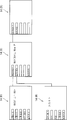
또한, 표시 제어부(24)는, 초기 화면(R)에서 메인테넌스 모드가 선택되었을 경우, 유저용 메인테넌스 화면(H ~ L)과 딜러용 메인테넌스 화면(M ~ Q)의 어느 한 쪽을 선택하는 메인테넌스 메뉴 톱 화면(G)(메인테넌스 선택 화면)을 표시시킨다. 이와 같이 하면, 메인테넌스 모드의 화면 계층을 깊게 하고, 유저의 오조작으로 딜러용 메인테넌스 화면(M ~ Q)으로 이행될 가능성을 저감할 수 있다. 이하, 초기 화면(R) 및 메인테넌스 모드의 각 화면(G ~ Q)에 대해서 설명한다. When the maintenance mode is selected on the initial screen R, the
도 10에 나타내는 바와 같이, 표시 제어부(24)는, 액정 표시부(14)의 초기 화면(R)에 있어서, 터치 조작 버튼(25a)의 설명문에 「메인테넌스」를 표시시킴과 함께, 터치 조작 버튼(25b)의 설명문에 「통상 작업」을 표시시킨다. 그리고, 터치 조작 버튼(25a)이 터치 조작되었을 경우는, 메인테넌스 메뉴 톱 화면(G)을 표시시키는 한편, 터치 조작 버튼(25b)이 터치 조작되었을 경우는, 통상 작업 모드의 디폴트 화면인 상술한 통상 표시 화면(A)을 표시시킨다. 10, the
표시 제어부(24)는, 메인테넌스 메뉴 톱 화면(G)에 있어서, 터치 조작 버튼(25a)의 설명문에 「메인테넌스」를 표시시키고, 터치 조작 버튼(25b)의 설명문에 「딜러 메뉴」를 표시시키고, 터치 조작 버튼(25e)의 설명문에 「돌아가기」를 표시시킨다. 그리고, 터치 조작 버튼(25a)이 터치 조작되었을 경우는, 유저용 메인테넌스 화면의 톱 화면인 메인테넌스 메뉴 화면(H)을 표시시키고, 터치 조작 버튼(25b)이 터치 조작되었을 경우는, 딜러용 메인테넌스 화면의 톱 화면인 딜러 메뉴 화면(M)을 표시시키고, 터치 조작 버튼(25e)이 터치 조작되었을 경우는, 초기 화면(R)을 표시시킨다. The
도 11에 나타내는 바와 같이, 표시 제어부(24)는, 메인테넌스 메뉴 화면(H)에 있어서, 터치 조작 버튼(25a)의 설명문에 「교환 시기」를 표시시키고, 터치 조작 버튼(25b)의 설명문에 「조정 치수」를 표시시키고, 터치 조작 버튼(25c)의 설명문에 「설정 가이드」를 표시시키고, 터치 조작 버튼(25d)의 설명문에 「DPF 재생」을 표시시키고, 터치 조작 버튼(25e)의 설명문에 「돌아가기」를 표시시킨다. 그리고, 터치 조작 버튼(25a)이 터치 조작되었을 경우는, 교환 시기 표시 화면(I)을 표시시키고, 터치 조작 버튼(25b)이 터치 조작되었을 경우는, 조정 치수 표시 화면(J)을 표시시키고, 터치 조작 버튼(25c)이 터치 조작되었을 경우는, 설정 가이드 표시 화면(K)을 표시시키고, 터치 조작 버튼(25d)이 터치 조작되었을 경우는, DPF 재생 순서 표시 화면(L)을 표시시키고, 터치 조작 버튼(25e)이 터치 조작되었을 경우는, 메인테넌스 메뉴 톱 화면(G)을 표시시킨다. 11, the
교환 시기 표시 화면(I)은, 엔진 오일, 작동유, T/M 오일, 엔진 오일 필터, HST 오일 필터, 연료 필터, 에어클리너 엘리먼트 등의 교환 시기를 나타내는 화면이며, 터치 조작 버튼(25a)의 설명문에 「이전 페이지」를 표시시키고, 터치 조작 버튼(25b)의 설명문에 「다음 페이지」를 표시시키고, 터치 조작 버튼(25d)의 설명문에 「처음으로 돌아가기」를 표시시키고, 터치 조작 버튼(25e)의 설명문에 「돌아가기」를 표시시킨다. 그리고, 터치 조작 버튼(25a)이 터치 조작되었을 경우는, 교환 시기 표시 화면(I)을 구성하는 복수의 화면 중, 현재의 표시 화면의 이전 페이지에 상당하는 화면을 표시시키고, 터치 조작 버튼(25b)이 터치 조작되었을 경우는, 교환 시기 표시 화면(I)을 구성하는 복수의 화면 중, 현재의 표시 화면의 다음 페이지에 상당하는 화면을 표시시키고, 터치 조작 버튼(25d)이 터치 조작되었을 경우는, 교환 시기 표시 화면(I)을 구성하는 복수의 화면 중, 처음의 페이지에 상당하는 화면(교환 시기 표시 화면(I))을 표시시키고, 터치 조작 버튼(25e)이 터치 조작되었을 경우는, 메인테넌스 메뉴 화면(H)을 표시시킨다. The replacement timing display screen I is a screen showing the replacement timing of engine oil, operating oil, T / M oil, engine oil filter, HST oil filter, fuel filter, air cleaner element, Quot; next page " is displayed on the comment of the
조정 치수 표시 화면(J)은, 주행 벨트, 작업기 입력(탈곡 구동), 전처리 입력(전처리 구동), 2번 구동, 1번 구동 등의 조정 치수를 나타내는 화면이며, 터치 조작 버튼(25a)의 설명문에 「이전 페이지」를 표시시키고, 터치 조작 버튼(25b)의 설명문에 「다음 페이지」를 표시시키고, 터치 조작 버튼(25d)의 설명문에 「처음으로 돌아가기」를 표시시키고, 터치 조작 버튼(25e)의 설명문에 「돌아가기」를 표시시킨다. 그리고, 터치 조작 버튼(25a)이 터치 조작되었을 경우는, 조정 치수 표시 화면(J)을 구성하는 복수의 화면 중, 현재의 표시 화면의 이전 페이지에 상당하는 화면을 표시시키고, 터치 조작 버튼(25b)이 터치 조작되었을 경우는, 조정 치수 표시 화면(J)을 구성하는 복수의 화면 중, 현재의 표시 화면의 다음 페이지에 상당하는 화면을 표시시키고, 터치 조작 버튼(25d)이 터치 조작되었을 경우는, 조정 치수 표시 화면(J)을 구성하는 복수의 화면 중, 처음의 페이지에 상당하는 화면(조정 치수 표시 화면(J))을 표시시키고, 터치 조작 버튼(25e)이 터치 조작되었을 경우는, 메인테넌스 메뉴 화면(H)을 표시시킨다. The adjustment dimension display screen J is a screen showing adjustment dimensions such as a traveling belt, a work machine input (threshing drive), a preprocessing input (preprocessing drive), a second drive, a first drive, Quot; next page " is displayed on the comment of the
설정 가이드 표시 화면(K)은, 벼 수확시의 선별 설정의 기준, 벼 수확시의 송진(送塵) 설정의 기준, 보리 수확시의 선별 설정의 기준, 보리 수확시의 송진 설정의 기준 등 작물 마다의 설정의 기준을 나타내는 화면이며, 터치 조작 버튼(25e)의 설명문에 「돌아가기」를 표시시킨다. 그리고, 터치 조작 버튼(25e)이 터치 조작되었을 경우는, 메인테넌스 메뉴 화면(H)을 표시시킨다. The setting guide display screen (K) can be used to set the criteria of the sorting setting at the time of rice harvesting, the standard of the setting of the dusting at the time of rice harvest, the standard of the sorting setting at the time of harvesting of barley, Quot; return " in the explanation text of the
DPF 재생 순서 표시 화면(L)은, 디젤 파티큘레이트 필터(DPF)의 재생 순서를 나타내는 화면이며, 터치 조작 버튼(25e)의 설명문에 「돌아가기」를 표시시킨다. 그리고, 터치 조작 버튼(25e)이 터치 조작되었을 경우는, 메인테넌스 메뉴 화면(H)을 표시시킨다. The DPF regeneration order display screen L is a screen showing the regeneration order of the diesel particulate filter (DPF), and displays " return " in the explanatory text of the
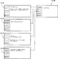
도 12에 나타내는 바와 같이, 표시 제어부(24)는, 딜러 메뉴 화면(M)에 있어서, 터치 조작 버튼(25a)의 설명문에 「입력 체크」를 표시시키고, 터치 조작 버튼(25b)의 설명문에 「이력」을 표시시키고, 터치 조작 버튼(25c)의 설명문에 「백업」을 표시시키고, 터치 조작 버튼(25d)의 설명문에 「고장 진단」을 표시시키고, 터치 조작 버튼(25e)의 설명문에 「돌아가기」를 표시시킨다. 그리고, 터치 조작 버튼(25a)이 터치 조작되었을 경우는, 입력 체크 화면(N)을 표시시키고, 터치 조작 버튼(25b)이 터치 조작되었을 경우는, 에러 이력 표시 화면(O)을 표시시키고, 터치 조작 버튼(25c)이 터치 조작되었을 경우는, 백업 화면(P)을 표시시키고, 터치 조작 버튼(25d)이 터치 조작되었을 경우는, 고장 진단 화면(Q)을 표시시키고, 터치 조작 버튼(25e)이 터치 조작되었을 경우는, 메인테넌스 메뉴 톱 화면(G)을 표시시킨다. 12, the
입력 체크 화면(N)은, 센서 등의 신호 입력을 체크하기 위한 화면이며, 체크하고 싶은 부품의 조작에 따라서, 표시 제어부(24)에 정상적인 신호가 입력되었을 경우, 그것을 부저음으로 통지한다. 이 화면(N)에서는, 터치 조작 버튼(25e)의 설명문에 「돌아가기」를 표시시키고, 그 터치 조작에 따라서 딜러 메뉴 화면(M)을 표시시킨다. The input check screen N is a screen for checking a signal input of a sensor or the like. When a normal signal is input to the
에러 이력 표시 화면(O)은, 에러 이력을 표시하는 화면이며, 터치 조작 버튼(25a)의 설명문에 「이전 페이지」를 표시시키고, 터치 조작 버튼(25b)의 설명문에 「다음 페이지」를 표시시키고, 터치 조작 버튼(25d)의 설명문에 「처음으로 돌아가기」를 표시시키고, 터치 조작 버튼(25e)의 설명문에 「돌아가기」를 표시시킨다. 그리고, 터치 조작 버튼(25a)이 터치 조작되었을 경우는, 에러 이력 표시 화면(O)을 구성하는 복수의 화면 중, 현재의 표시 화면의 이전 페이지에 상당하는 화면을 표시시키고, 터치 조작 버튼(25b)이 터치 조작되었을 경우는, 에러 이력 표시 화면(O)을 구성하는 복수의 화면 중, 현재의 표시 화면의 다음 페이지에 상당하는 화면을 표시시키고, 터치 조작 버튼(25d)이 터치 조작되었을 경우는, 에러 이력 표시 화면(O)을 구성하는 복수의 화면 중, 처음의 페이지에 상당하는 화면(에러 이력 표시 화면(O))을 표시시키고, 터치 조작 버튼(25e)이 터치 조작되었을 경우는, 딜러 메뉴 화면(M)을 표시시킨다. The error history display screen O is a screen for displaying an error history and displays a "previous page" in the comment of the
백업 화면(P)은, 각종의 데이터나 소프트웨어를 백업하기 위한 화면이며, 이 화면(P)에서는, 터치 조작 버튼(25e)의 설명문에 「돌아가기」를 표시시키고, 그 터치 조작에 따라서 딜러 메뉴 화면(M)을 표시시킨다. The backup screen P is a screen for backing up various kinds of data and software. In this screen P, " return " is displayed in the explanation text of the
고장 진단 화면(Q)은, 전장(電裝) 부품의 트러블의 유무에 대해서 체크를 행하기 위한 화면이며, 터치 조작 버튼(25a)의 설명문에 「자동 체크」를 표시시키고, 터치 조작 버튼(25b)의 설명문에 「수동 체크」를 표시시키고, 터치 조작 버튼(25e)의 설명문에 「돌아가기」를 표시시킨다. 그리고, 터치 조작 버튼(25a)이 터치 조작되었을 경우는, 자동 체크 모드를 실행하고, 터치 조작 버튼(25b)이 터치 조작되었을 경우는, 수동 체크 모드를 실행하고, 터치 조작 버튼(25e)이 터치 조작되었을 경우는, 딜러 메뉴 화면(M)을 표시시킨다. The trouble diagnosis screen Q is a screen for checking the presence or absence of troubles of electrical components and displays "AUTOMATIC CHECK" in the explanation text of the
다음에, 표시 제어부(24)의 입출력 및 표시 제어의 제어 순서에 대해서, 도 13 및 도 14를 참조하여 설명한다. Next, the control procedure of the input / output and display control of the
도 13에 나타내는 바와 같이, 표시 제어부(24)는, 액정 표시부(14)의 터치 패널 조작 신호, 물리적 조작 버튼(26a ~ 26e)의 조작 신호, 카메라 화상, 센서 정보, 설정 정보 등을 입력하고, 이들의 입력 신호에 기초하여 액정 표시부(14)의 표시 제어를 행한다. 13, the
도 14에 나타내는 바와 같이, 표시 제어에서는, 우선, 엔진이 정지 상태인지 아닌지를 판단함과 함께(S1), 키 스위치의 ON 조작의 유무를 판단하고(S2), 여기서 양 판단의 결과가 모두 YES인 경우는, 액정 표시부(14)에 초기 화면(R)을 표시시킨다(S3). 초기 화면(R)의 표시 후는, 모드 선택 조작을 판단하고(S4), 여기서, 메인테넌스 모드가 선택되었을 경우는, 메인테넌스 모드를 실행한다(S5). 메인테넌스 모드의 실행 중은, 초기 화면(R)으로의 돌아가기 조작이 가능하고, 상기 돌아가기 조작의 판단(S6)에 기초하여 초기 화면(R)을 재표시시킨다. 한편, 초기 화면(R)에서 통상 표시 모드가 선택되었을 경우는, 통상 표시 모드를 실행한다(S7). 그리고, 통상 표시 모드를 선택한 후는, 초기 화면(R)으로의 이행이 제한된다. 즉, 엔진 정지 상태에서 키 스위치가 ON 되었을 경우에만 초기 화면(R)을 표시시키므로, 통상 작업 모드를 선택한 후나, 엔진 시동에 따라서 통상 작업 모드로 이행한 후는, 엔진의 정지 조작을 행하지 않는 한, 통상 작업 모드로부터 메인테넌스 모드로의 이행이 금지된다. As shown in Fig. 14, in the display control, first, it is judged whether or not the engine is in the stop state (S1), the presence or absence of the ON operation of the key switch is judged (S2) , An initial screen R is displayed on the liquid crystal display unit 14 (S3). After the initial screen R is displayed, the mode selection operation is determined (S4). If the maintenance mode is selected, the maintenance mode is executed (S5). During execution of the maintenance mode, an operation to return to the initial screen R is possible, and the initial screen R is redisplayed based on the judgment (S6) of the return operation. On the other hand, when the normal display mode is selected in the initial screen R, the normal display mode is executed (S7). After the normal display mode is selected, the transition to the initial screen R is restricted. That is, since the initial screen R is displayed only when the key switch is turned on in the engine stop state, after the normal operation mode is selected, or after shifting to the normal operation mode according to the engine start, , The transition from the normal operation mode to the maintenance mode is prohibited.
다음에, 조종부(7)에 배치되는 조작 도구의 상세에 대해서, 도 7 및 도 15 ~ 도 19를 참조하여 설명한다. Next, details of the operating tool disposed in the
조종부(7)에 배치되는 조작 도구는, 마이크로컴퓨터 등으로 구성하는 전자 제어 장치(ECU)(Electronic Control Unit)를 통하여 기체 각 부의 작동을 제어한다. 혹은, 기계적으로 연계하여 기체 각 부의 작동을 제어한다. 또한, 전자 제어 장치(ECU)는, 기체에 복수 마련하고, 각 유닛은 컨트롤 에리어 네트워크(CAN)로 상호 통신 가능하게 연결하고 있다. 그리고, 구체적으로는, 도 15에 나타내는 바와 같이, 운전석(9)의 전방 우측쪽에 기체의 선회나 전처리부(2)의 승강을 행하는 조작 도구인 멀티 스티어링 레버(38)를 마련하고, 멀티 스티어링 레버(38)의 후방에, 멀티 스티어링 레버(38)를 조작할 때에 사용하는 암 레스트(39)를 마련하고 있다. The manipulation tool disposed in the
멀티 스티어링 레버(38)는, 전후·좌우로 요동(搖動) 가능하게 지지되고, 기초부에 마련되는 조향 포텐셔미터와 리프트 승강 포텐셔미터에 의해서, 멀티 스티어링 레버(38)의 조작 각도가 ECU에 입력된다. 또한, ECU는, 멀티 스티어링 레버(38)의 좌우 방향의 경도(傾倒)를 검출하면, 솔레노이드 밸브에 의해서 유압 실린더를 작동시키고, 미션 케이스의 사이드 클러치를 끊고, 방향의 미조정을 행한다. 혹은, 한층 더한 경도 조작을 검출하면, 멀티 스티어링 레버(38)의 조작 각도에 따라서, 주행부(8)의 선회 방향 내측이 되는 구동력을 컨트롤하여 선회력을 변경한다. 그리고, 멀티 스티어링 레버(38)의 전후 방향의 경도를 검출하면, 유압 리프트 실린더를 작동시켜서, 전처리부(2)를 멀티 스티어링 레버(38)의 조작 각도에 비례한 승강 속도로 승강시킨다. The steering angle of the
운전석(9)의 전방 좌측쪽에는, 설정 조작 패널(13)이 마련된다. 설정 조작 패널(13)은, 스위치 케이스(42)에 제1의 조작 도구군을 마련하여 구성되어 있다. 그리고, 제1의 조작 도구군은, 각 기능마다 나누어 구획된 수지 시트(43)의 복수의 영역에, 조작 도구와 필요에 따라서 LED(Light Emitting Diode) 램프를 배치한다. 또한, 수지 시트(43)는 스위치 케이스(42)에 붙여, 조작 도구의 명칭이나 모양을 인쇄하고 있다. 이하, 제1의 조작 도구군의 각각의 조작 도구에 대해서 설명한다. On the front left side of the driver's
먼저, 스위치 케이스(42)의 우측쪽의 전부(前部)에, 예취 클러치와 탈곡 클러치를 단속(斷續)하는 조작 도구인 파워 클러치 스위치(44)와, 그 전환 상태를 표시하는 LED 램프(45)를 마련한다. 그리고, 파워 클러치 스위치(44)는, 모멘터리형의 시소 스위치로 구성하고, 스위치(44)의 전부(前部)측을 누를 때마다 탈곡 클러치 ON, 예취 클러치 ON으로 전환되고, 후부측을 누를 때마다 예취 클러치 OFF, 탈곡 클러치 OFF로 전환된다. 또한, 상기 파워 클러치 스위치(44)를 조작하면, ECU는 클러치 모터를 작동시켜서, 벨트 텐션 클러치 방식의 탈곡 클러치, 및 예취 클러치를 단속한다. First, a
또한, 스위치 케이스(42)의 우측쪽의 후부에, 엔진 회전수를 설정하는 조작 도구인 엔진 회전 자동 다이얼(46)과 자동 제어 상태를 표시하는 LED 램프(47)를 마련한다. 그리고, 엔진 회전 자동 다이얼(46)은, 모멘터리형의 스위치와 볼륨(가변 저항기)을 작동시키고, 다이얼(46)을 누를 때마다 스위치가 온이 되고, 엔진 회전 자동 제어가 ON·OFF 된다. 또한, 다이얼(46)에 의해서 볼륨을 회전 조작하면, 회전 각도에 대응한 엔진 회전수로 설정된다. 또한, 엔진 회전 자동 다이얼(46)의 신호에 기초하여 엔진 ECU는, 상술한 엔진 회전 자동 제어를 행하거나, 혹은 엔진 회전 자동 다이얼(46)로 설정한 엔진 회전수가 되도록 엔진을 제어한다. An engine rotation
또한, 스위치 케이스(42)의 중앙측쪽의 전부(前部)에, 리프트 셧 스위치(48)와 그 상태를 표시하는 LED 램프(49)를 마련한다. 또한, 스위치 케이스(42)의 중앙측쪽의 후부에, 방향 자동 스위치(50)와 탈곡 깊이 자동 제어를 ON OFF 하는 조작 도구인 탈곡 깊이 자동 스위치(52), 및 그것들의 상태를 표시하는 LED 램프(51, 53)를 좌우에 병설한다. 그리고, 이들의 스위치(48, 50, 52)는 어느 것도 텍타일 스위치로 구성하고, 스위치 케이스(42)의 표면에 마련하는 수지 시트(43)의 하방에 마련되어, 스위치(48, 50, 52)로의 먼지의 침입을 방지하고 있다. A lift shut
또한, 리프트 셧 스위치(48)는, 예취 탈곡 작업시에 전처리부(2)가 리프트 포텐셔미터에 의해서 소정의 높이까지 상승된 것을 검출했을 때에, ECU를 통하여 예취 클러치를 끊어서, 예취부(B)의 구동을 자동적으로 정지시키는 제어를, 유효, 혹은 무효로 하는 전환 스위치이며, 상기 리프트 셧 스위치(48)를 ON으로 하면, 1행정의 곡간(穀桿)의 예취를 마치고 다음 행정의 예취를 행하기 위해서 전처리부(2)를 상승시키고, 그 후에 기체의 선회나 이동 주행을 행할 때에, 전처리부(2)의 구동이 자동적으로 정지되기 때문에, 전처리부(2)의 구동 진동이나 소음의 발생이 방지된다. The lift shut
또한, 방향 자동 스위치(50)는, 방향 자동 제어를 ON OFF 하는 스위치이며, 상기 방향 자동 제어는, 예취 작물의 조간(條間)에 대해서 중앙의 디바이더의 통과 위치를 방향 센서로 감지하고, 디바이더가 곡간 조열(條列)에 너무 가까워지면, ECU가 사이드 클러치를 단속시켜서, 중앙의 디바이더가 조간의 중앙을 통과하도록 기체의 진행 방향을 제어한다. 또한, 탈곡 깊이 자동 스위치(52)는, 탈곡 깊이 자동 제어를 ON OFF 하는 스위치이며, 상기 탈곡 깊이 자동 제어는, 곡간의 반송 중도에 마련한 센서로 곡간의 장단을 검출하고, 탈곡부(3)에 공급하는 곡간의 탈곡 깊이가 적정하게 되도록, ECU가 탈곡 깊이 반송 장치를 모터로 상하 작동시켜서 제어한다. The direction
그리고, 스위치 케이스(42)의 좌측쪽의 전부(前部)에, 기체를 경사시키는 조작 도구인 수평 수동 레버(54)와 수평 다이얼(55)과 수평 자동 스위치(56)와 수평 자동 제어 상태를 표시하는 LED 램프(57)를 마련한다. 이 중, 수평 수동 레버(54)는, 전후 및 좌우 조작이 자유로운 크로스 레버 스위치로 구성하고, 수평 수동 레버(54)를 왼쪽 또는 오른쪽으로 조작하면, ECU는 기체를 좌경사 또는 우경사시키고, 수평 수동 레버(54)를 전 또는 후로 조작하면, ECU는 기체를 전경사 또는 후경사시킨다. A horizontal
또한, 수평 자동 스위치(56)는, 텍타일 스위치로 구성하고, 수평 자동 스위치(56)를 누를 때마다 좌우 수평 자동 제어를 ON OFF 하고, 또한, 전후 수평 자동 제어를 ON OFF 한다. 또한, 수평 다이얼(55)은, 모멘터리형의 스위치와 볼륨을 작동시키고, 다이얼(55)을 누르면 스위치가 온이 되고, 기체(3)의 전후 경사를 기준으로 하는 기체 프레임과 주행부(8)의 트랙 프레임이 평행이 되는 위치로 되돌린다(전후 수평 리셋). 또한, 수평 다이얼(55)에 의해서 볼륨을 회전시키면, 그 볼륨의 회전 각도가, 좌우 수평 자동 제어시의 목표 경사 각도로 설정된다. 덧붙여서 수평 다이얼(55)의 중앙 조작 위치는, 기체를 절대 수평으로 제어하는 위치가 된다. The horizontal
또한, 스위치 케이스(42)의 좌측쪽의 후부에, 전처리부(2)의 하강 위치를 설정하는 조작 도구인 예취 높이 다이얼(61)을 마련한다. 예취 높이 다이얼(61)은 볼륨을 작동시키고, 그 회전 각도가 전처리부(2)의 하강 위치의 설정치가 된다. 또한, 예취 높이 다이얼(61)을 최저보다 더 돌리면, 전처리부(2)의 하강 위치의 설정이 해제된다. 그리고, 전처리부(2)의 하강 위치의 설정이 해제되면, ECU는, 멀티 스티어링 레버(38)의 전후 이동 조작에 의해서 유압 리프트 실린더를 작동시켜서, 전처리부(2)를 자유롭게 승강시킨다. A cut-off
그러나, 전처리부(2)의 하강 위치의 설정이 행해지고 있을 때는, ECU가 예취 높이 다이얼(61)로 설정되는 설정치와 예취부(B)의 승강 위치를 검출하는 리프트 포텐셔미터와의 값을 비교하고, 양 자의 값이 일치했을 때에, 유압 리프트 실린더(5)의 하강 작동을 정지시키고, 전처리부(2)의 하강을 정지시킨다. 또한, 그 상태에서 예취 높이 다이얼(61)을 조작하여 설정치를 변경하면, ECU는 설정치에 추종시켜서 전처리부(2)의 승강을 행한다. However, when the lowering position of the
기체의 주행 변속을 행하는 조작 도구로서는, 주 변속 레버(62)와 부 변속 레버(63)가 마련된다. 이 중, 주 변속 레버(62)는, 중립(정지)의 가로 홈(64a)과 전진측의 세로 홈(64b)과 후진측의 세로 홈(64c)을 구비하는 가이드 홈(64)에 삽입 통과시켜, 상단에 그립(62a)을 구비하는 전후·좌우 회동 가능한 조작 레버로서, 주 변속 레버(62)의 전후 이동 조작에 의해서 주행용의 정유압식 무단 변속 장치(HST)의 서보 밸브를 전환하고, 전후진의 전환과 무단 변속을 행한다. The main
또한, 주 변속 레버(62)는, 운전석(31)으로부터 일어나서 조작했을 경우에도, 용이하게 조작할 수 있도록, 그 전후 회동 조작 영역(전진측과 후진측에 걸친 가이드 홈(64)의 영역)을 가능한 한 기체 전방측에 설정하는 것으로서, 덧붙여서 실시형태에서는 중립의 가로 홈(64a)이 운전석(9)의 좌석면 선단보다 전방에 위치하도록 배치한다. The main
또한, 부 변속 레버(63)는, 주 변속 레버(62)의 전진측 가이드 홈(64b)의 기체 안쪽 측에 전후 회동 가능하게 병설하고, 부 변속 레버(63)를 그 그립(63a)을 잡아서 가이드 홈(65a)을 따라서 전후 이동 조작하면, 미션 케이스에 마련한 톱니바퀴식 부 변속 장치를, 예를 들면, 중립, 저속, 표준(중속), 주행(고속)으로 기계적으로 전환한다. 또한, 부 변속 레버(63)의 저속 전환 위치에서 좌측으로 조작하여 가로 홈(65b)의 좌단으로 조작하면, 미션 케이스에 마련하는 선회력 전환 장치를 기계적으로 스핀 턴으로 전환한다. 또한, 부 변속 레버(63)의 후방에, 콤비네이션 스위치(66)를 마련한다. 상기 콤비네이션 스위치(66)는, 라이팅 스위치와 플래셔 스위치와 혼 스위치를 구비한다. The auxiliary
주 변속 레버(62)의 후방에는, 제2의 조작 도구군이 마련된다. 제2의 조작 도구군은, 선회 모드 설정 다이얼(67)과 당기 풍량 설정 다이얼(68)과 선별 다이얼(69)과 DPF 스위치(70)로 구성하고, 각 조작 도구는 조작 박스에 장착한 커버(71)의 전후 방향으로 정렬시킨 각각의 개구부로부터, 조작부를 돌출시켜서 마련한다. 그리고, 이 중, 선회 모드 설정 다이얼(67)은, 볼륨을 회전 조작하고, 그 볼륨의 회전 각도에 의해서 ECU는, 브레이크 턴 모드, 감속 턴 모드, 혹은 풀 모드 턴 모드로 전환함과 함께, 풀 모드 턴에 있어서의 선회력의 조정압을 설정한다. On the rear side of the main
즉, 미션 케이스(37)에 마련하는 선회력 전환 장치는, ECU의 제어에 기초하여, 사이드 클러치가 끊긴 선회 내측이 되는 주행부(8)를 제동시키는 브레이크 턴과, 사이드 클러치가 끊긴 선회 내측이 되는 주행부(8)를 감속하여 외측의 주행부(8)와 동일 방향으로 구동하는 감속 턴과, 감속 턴 및 브레이크 턴을 연속하여 행하는 풀 모드 턴과, 사이드 클러치가 끊긴 선회 내측이 되는 주행부(8)를 역회전시키는 스핀 턴으로 전환 가능하게 이루어진다. That is, the rotary force conversion apparatus provided in the transmission case 37, on the basis of the control of the ECU, the side with the brake turned to clutch the
따라서, 선회 모드 설정 다이얼(67)을 브레이크 턴측, 또는 감속 턴측으로 최대한 회전시키면, ECU는 선회력 전환 장치를 브레이크 턴, 또는 감속 턴으로 전환하는 모드가 되고, 그 이외의 회전 각도에서는, 선회력 전환 장치를 풀 모드 턴으로 전환하는 모드가 된다. 또한, 부 변속 레버(63)가 저속 전환 위치에서 좌측으로 조작되면, ECU는 이것을 스위치에 의해서 검출하고, 스핀 턴으로 전환하는 모드가 된다. 또한, 상기 각 선회 모드에 있어서, 실제로 선회력 전환 장치가 전환되는 타이밍은, 멀티 스티어링 레버(38)의 좌우 방향의 경도 각도에 의해서 결정된다. Therefore, when the turning
또한, 당기 풍량 설정 다이얼(68)은 볼륨을 작동시키고, 그 볼륨의 회전 각도에 의해서 탈곡부(3)의 당기 팬의 풍량이 설정된다. 그리고, 당기 팬의 풍량이 설정되면, ECU는 벨트 무단 변속 장치의 분할 풀리의 개도(開度)를 모터에 의해서 변경하고, 설정된 풍량이 얻어지도록 제어한다. 또한, 선별 다이얼(69)은, 모멘터리형의 스위치와 볼륨을 작동시키고, 다이얼(69)을 누를 때마다 스위치가 온이 되고, 선별 자동 제어가 ON·OFF 됨과 함께, 자동 제어 상태를 표시하는 LED 램프(72)가 점등, 또는 소등된다. 또한, 다이얼(69)에 의해서 볼륨을 회전 조작하면, 선별 자동 제어에 있어서의 벼와 보리 등의 재료 조건이 설정된다. 또한, DPF 스위치(70)는, 모멘터리형의 스위치에 의해서 구성하고, DPF 스위치(70)를 온 하면, 상술한 DPF 재생이 행해진다. Further, the current air
이상, 조종부(7)에 마련하는 조작 도구에 대해서 설명했지만, 다음에 예취 탈곡 작업 중에 있어서의 오퍼레이터의 동향에 대해서 고찰하면, 오퍼레이터는 운전석(9)에 앉은 상태에서 기체 각 부의 조작을 행하는 경우도 물론 있다. 그러나, 이랑 가의 예취시의 전처리부(2)의 승강 조작, 회전 예취시의 기체의 전후진 조작, 조(條) 맞춤 혹은 조(條) 예취 및 횡(橫) 예취시의 기체의 방향 수정 조작 등에 있어서, 이들의 조작을 신속, 그리고 정확하게 행하기 위해서, 오퍼레이터는 운전석(9)으로부터 일어서는 경우가 많다. In the following, a description will be given of the operation of the operator during the cutting and treading operation. When the operator performs the operation of each part of the body while sitting on the driver's
또한, 논밭의 단단하고 무른 정도에 따른 주행부(8)의 침하, 혹은 기체의 경사에 기초하는 예취 높이에의 대응, 또한, 예취 재료의 도복(倒伏), 혹은 높이가 긴 잡초를 동시에 예취할 때의 대응 등에 있어서, 오퍼레이터는 운전석(9)으로부터 일어서서, 기체 전방의 논밭 상태, 혹은 예취 재료 상태를 확인하면서, 조작 도구를 조작하여 신속, 그리고 적정하게 대응하는 것이 요구된다. In addition, it is also possible to cope with the settlement height of the running
즉, 예취 탈곡 작업시에는, 기체의 경사 조작(수평 수동 레버(54)), 혹은 예취 높이 설정치의 변경(예취 높이 다이얼(55))에 의한 예취 높이의 조절, 탈곡 깊이 자동 제어의 ON OFF 조작(탈곡 깊이 자동 스위치(52))에 의한 탈곡 깊이의 조절, 이랑 가의 베어 올리기 조작에 수반하는 예취부(3)의 계속적인 구동 조작(리프트 셧 스위치(48)), 조 예취 및 횡(橫) 예취에 수반하는 방향 자동 제어의 ON OFF 조작(방향 자동 스위치(50)), 엔진 부하의 증감에 의한 엔진 회전수의 조절(엔진 회전 자동 다이얼(47)), 벼 배출 등을 위한 논밭 내 이동 주행시의 예취 탈곡 클러치의 단속 조작(파워 클러치 스위치(44)) 등이 요구된다. That is, at the time of the cutting and shearing operation, adjustment of the cutting height by the inclination of the base (horizontal manual lever 54) or the change of the cutting height setting value (cutting height dial 55) (Lift shut switch 48) of the
따라서, 오퍼레이터가 운전석(9)으로부터 일어서서, 기체 전방의 논밭 상태, 내지 예취 재료 상태를 보면서, 혹은 다소 눈을 뗀 사이에, 조작 도구를 신속, 그리고 적정하게 조작하여 대응하기 위해서는, 이들의 조작 도구가 오퍼레이터의 전방에 있고, 즉석에서 손이 닿는 위치에 있는 것이 바람직하다. 여기서, 본 발명은, 관계하는 인간 공학적인 견지에서, 조작 도구의 배치 개소를 결정한다. 또한, 조작 도구의 기능에 따라서, 그 조작 빈도에는 자연스럽게 높고 낮음의 차이가 발생한다. 여기서, 본 발명은, 콤바인을 취급하는 경우에, 제일 장시간 작업이 되는 예취 탈곡 작업 중을 타겟으로, 이 예취 탈곡 작업 중의 조작 도구의 조작 빈도에 기초하여, 그 배치 개소를 최종적으로 결정한다. Therefore, in order for the operator to stand up from the driver's
구체적으로는, 조작 도구의 조작 빈도에 기초하여, 제1의 조작 도구군과 제2 조작 도구군으로 나눈다. 그리고, 운전석(9)의 측방 전부(前部)에, 예취 탈곡 작업 중에 사용하는 조작 빈도가 높은 제1의 조작 도구군을 배치한다. 이것에 의해, 오퍼레이터가 운전석(9)으로부터 일어서서 전방을 주시하면서 예취 탈곡 작업을 행하고 있을 때, 제1의 조작 도구군은 오퍼레이터의 전방에 위치하여, 오른손으로 멀티 스티어링 레버(38)를 잡아서 기체의 방향 수정 등을 행하고 있을 때라도, 제1의 조작 도구군의 조작 도구에 왼손을 뻗어서, 이것을 조작할 수 있어, 신속한 대응이 가능해진다. Specifically, the first manipulation tool group and the second manipulation tool group are divided based on the operation frequency of the manipulation tool. A first operating tool group having a high frequency of operation to be used during the cutting operation is arranged on the front side of the driver's
또한, 제1의 조작 도구군의 후방에는, 기체의 주행 변속을 행하는 조작 도구(주 변속 레버(62), 부 변속 레버(63))를 배치한다. 이것에 의해, 오퍼레이터가 운전석(9)으로부터 일어선 상태라도, 기체의 전후진 조작, 혹은 논밭 내 이동 속도(중속, 또는 고속)로 변속할 수 있다. 그리고, 기체의 주행 변속을 행하는 조작 도구의 후방에는, 조작 빈도가 낮은 제2의 조작 도구군을 배치한다. 그런데, 상기 제2의 조작 도구군은, 예취 탈곡 작업 개시시, 또는 종료 후에 한번, 조작하면 충분하고, 예취 탈곡 작업 중에는 거의 조작하는 것이 드문 조작 도구(선회 모드 설정 다이얼(67), 당기 풍량 설정 다이얼(68), 선별 다이얼(69), DPF 스위치(70))이기 때문에, 오퍼레이터가 운전석(9)에 앉은 상태로 침착하게 조작할 수 있으면 충분하다. Further, an operation tool (main
또한, 제2의 조작 도구군을 제1의 조작 도구군에 더하면, 제1의 조작 도구군의 조작 도구 수가 증가하여 제1의 조작 도구군의 설치 스페이스를 넓게 취하지 않으면 안되고, 후방에 마련하는 기체의 주행 변속을 행하는 조작 도구(주 변속 레버(62), 부 변속 레버(63))의 배치 위치에 지장을 초래할 우려가 있다. 그러나, 제2의 조작 도구군으로 나누어서, 제1의 조작 도구군의 조작 도구 수를 필요 최소한으로 제한하게 하는 것에 의해서, 이것을 해소할 수 있다. 또한, 제1의 조작 도구군의 조작 도구 수가 적고, 양 자를 더한 것과 같이 조작 도구가 혼재하지 않기 때문에, 필요한 조작 도구를 실수없이 선정할 수 있고, 신속한 대응에 의해서 예취 탈곡 정밀도를 향상시킬 수 있다. When the second group of manipulation tools is added to the first group of manipulation tools, the number of manipulation tools of the first manipulation tool group must be increased and the installation space of the first manipulation tool group must be increased. (The main
그리고, 본 발명은, 제1의 조작 도구군 중의 각각의 조작 도구의 배치에 대해서도 고려한다. 즉, 제1의 조작 도구군의 조작 도구 중에도 자연스럽게 조작 빈도에 높고 낮음의 차이가 발생한다. 예를 들면, 예취 작업 전후, 혹은 논밭 내 이동 주행의 전후에는, 예취 클러치와 탈곡 클러치의 단속 조작을 필요로 한다. 또한, 예취 클러치와 탈곡 클러치의 단속 조작을 행하면, 그것에 맞추어서 엔진 회전수를 예취 탈곡 작업에 필요한 고회전으로 변경하거나, 또는 이동 주행에 적절한 회전수로 변경하거나, 혹은 일시적으로 기체를 정지하는 대기 상태에서는, 아이들링 상태로 변경하는 등의 조작이 필요하고, 이들의 조작은, 다른 조작에 비하여 조작 빈도가 높다. The present invention also considers the arrangement of the respective operation tools in the first group of operation tools. That is, even in the operating tool of the first operating tool group, there is a difference in the frequency of operation naturally high and low. For example, intermittent operation of the cutting clutch and the threshing clutch is required before and after the cutting operation or before or after the traveling in the field. In addition, when the intermittent operation of the cut-off clutch and the thresh-up clutch is performed, the engine speed is changed to a high speed necessary for the shearing-treading work, or the speed is changed to a suitable speed for traveling, , An idling state, and the like. These operations are more frequently performed than the other operations.
따라서, 제1의 조작 도구군 중에서도 조작 빈도가 높은 예취 클러치와 탈곡 클러치를 단속하는 조작 도구(파워 클러치 스위치(44))와, 엔진 회전수를 설정하는 조작 도구(엔진 회전 자동 다이얼(46))를, 제1의 조작 도구군을 마련하는 스위치 케이스(42)의 가장 오른쪽에 배치한다. 그러므로, 이들의 조작 도구는 운전석(31)에 가장 가깝게 되고, 운전석(31)으로부터 일어선 오퍼레이터가 왼손으로 재빠르게 조작할 수 있다. 또한, 이들의 조작 도구의 조작 타이밍은 대략 전후이기 때문에, 한쪽의 조작 도구를 조작한 후, 다른쪽의 조작 도구에의 이행을 극히 단시간에 행할 수 있고, 조작 빈도가 높다고 해도 오퍼레이터의 피로를 경감하여, 작업 능률을 향상시킬 수 있다. Therefore, an operation tool (power clutch switch 44) for interrupting the cut-off clutch and the descending clutch having a high operation frequency among the first operating tool group, an operation tool (engine rotation automatic dial 46) Is disposed on the rightmost side of the
또한, 예취 탈곡 작업 중에 전처리부(2)나 탈곡부(3)에 막힘 등이 발생했을 때에는, 예취 클러치와 탈곡 클러치를 단속하는 조작 도구(파워 클러치 스위치(44))를 조작하여, 재빨리 예취부(B)와 탈곡부(C)를 정지시킬 수 있고, 그것에 의해 심각한 막힘의 발생을 방지할 수 있다. 또한, 엔진 회전수를 설정하는 조작 도구(엔진 회전 자동 다이얼(46))를 액정 표시부(14)에 가장 가까운 측에 마련하기 때문에, 액정 표시부(14)에 표시되는 엔진 회전수를 시야에 넣으면서 적정한 엔진 회전수로 재빠르게 설정할 수 있음과 함께, 동일하게 액정 표시부(14)에 표시되는 엔진 부하율에 기초하여 엔진 회전수를 증감하여, 여유를 가진 엔진 부하 상태에서 예취 탈곡 작업을 능률적으로 행할 수 있다. When clogging or the like occurs in the
또한, 예취 클러치와 탈곡 클러치를 단속하는 조작 도구(파워 클러치 스위치(44))와 엔진 회전수를 설정하는 조작 도구(엔진 회전 자동 다이얼(46))를 제외한 제1의 조작 도구군의 조작 빈도는, 상세하게 검토하면 상호의 조작 도구 사이에서 차이가 있는데, 그 차이는 별로 크지 않다. 따라서, 여기에서는 조작 도구의 기능에 기초한 관련성(모음)을 제1로 고려함과 함께, 제2로 주위의 설치 환경, 조작성 등을 종합적으로 판단하여, 조작 도구의 배치를 결정한다. The operating frequency of the first operating tool group excluding the operating tool (power clutch switch 44) for interrupting the cutting clutch and the threshing clutch and the operating tool for setting the engine speed (engine rotating automatic dial 46) , There is a difference between mutual manipulation tools when examined in detail, but the difference is not so great. Therefore, in this case, the relevance (vowel) based on the function of the operation tool is considered first, and the arrangement environment of the operation tool is determined by comprehensively determining the surrounding environment, operability, and the like.
즉, 제1의 관점으로부터 기체의 경사 제어에 관한 수평 수동 레버(54)와 수평 다이얼(55)과 수평 자동 스위치(56), 및 수평 자동 제어 상태를 표시하는 LED 램프(57)는, 동일 영역에 모아서 배치한다. 또한, 자동 제어의 ON OFF 만을 행하는 스위치는, 동일 영역, 또는 근접하여 모아서 배치한다. 또한, 제2의 관점으로부터 제1의 조작 도구군은, 기체의 주행 변속을 행하는 조작 도구(주 변속 레버(62), 부 변속 레버(63))의, 특히 그립에 따라서 오퍼레이터가 보았을 때, 그림자가 걸쳐지기 쉽다. 여기서, 그림자가 걸쳐져도 조작 도구의 조작성을 해치지 않는 배치로 한다. That is, from the first viewpoint, the horizontal
그리고, 구체적으로는, 리프트 셧 스위치(48)와 그 상태를 표시하는 LED 램프(49), 및 방향 자동 스위치(50)와 탈곡 깊이 자동 스위치(52), 및 그것들의 상태를 표시하는 LED 램프(51, 53)는, 자동 제어의 ON OFF 만을 실시하는 스위치이기 때문에, 모아서 배치한다. 또한, 이들의 자동 제어를 ON OFF 하는 스위치(48, 50, 52)는, 손가락의 터치 조작으로 자동 제어의 ON OFF 조작을 행하는 것이기 때문에, 조작 공간을 별로 필요로 하지 않는다. More specifically, a lift shut
또한, 이들의 스위치(48, 50, 52)는, 어느 쪽도 텍타일 스위치로 구성하고, 스위치 케이스(42)의 표면에 마련하는 수지 시트(43)로부터의 스위치의 돌출량이 적고, 주행 변속을 행하는 주 변속 레버(62)가 최대 전진측으로 조작되고, 오퍼레이터가 보아 그 그립(62a)의 그림자측으로 되어도, 상기 작은 평면적인 조작 공간과 그립과 스위치의 간격을 넓게 취할 수 있는 상하 방향의 조작 공간이 서로 어울려서, 조작에 지장을 초래하지 않기 때문에, 주 변속 레버(62) 전방의 스위치 케이스(42)의 중앙측쪽에 마련한다. 또한, 주 변속 레버(62)가 최대 전진측으로 조작되고, 오퍼레이터가 보아 그 그립(62a)의 그림자측이 되는 바로 밑(直下)에는, 빈 공간(S)을 마련하고, 이 빈 공간(S)을 물품 수납 등으로 할 수도 있다. Both of these
또한, 수평 수동 레버(54)는, 크로스 레버 스위치로 구성하고, 레버(54)의 스위치 케이스(42)로부터의 돌출량은 많고, 또한, 레버 조작을 위한 넓은 조작 공간을 필요로 하기 때문에, 기체(3)의 주행 변속을 행하는 조작 도구(주 변속 레버(62), 부 변속 레버(63))로부터 가장 떨어진 스위치 케이스(42)의 좌측쪽의 전부(前部)에 마련한다. 또한, 수평 자동 스위치(56)는, 자동 제어를 ON OFF 하는 스위치로 조작 공간을 별로 필요로 하지 않기 때문에, 수평 수동 레버(54)와 동일 영역에 마련하지만, 리프트 셧 스위치(48)와 나란하게, 주 변속 레버(62) 전방이 되는 수평 수동 레버(54)의 우측에 마련한다. 또한, 수평 자동 스위치(56)에 부수하는 수평 자동 제어 상태를 표시하는 LED 램프(57)도 수평 자동 스위치(56)에 근접하여 마련한다. 남는 수평 다이얼(55)은 수평 수동 레버(54)의 후방에 마련한다. Since the horizontal
그리고, 마지막으로 남은 예취 높이 다이얼(61)은, 스위치 케이스(42)의 좌측쪽의 후부에 마련한다. 또한, 수평 다이얼(55)과 예취 높이 다이얼(61)은, 다이얼을 잡아서 회전 조작하기 위해 넓은 조작 공간을 필요로 하고, 또한, 다소 스위치 케이스(42)로부터 돌출하기 때문에, 주행 변속을 행하는 조작 도구의 그림자측으로부터 떨어뜨려서 이들의 조작성을 확보한다. 또한, 이들 다이얼(55, 61)은, 부 변속 레버(63)의 전방측에 마련하게 되는데, 부 변속 레버(63)를 최대로 전방측으로 경도(傾倒)시킨 변속단은 주행(고속)이 되기 때문에, 예취 탈곡 작업 중에 부 변속 레버(63)가, 상기 주행단으로 변속되는 일은 적고, 이들의 다이얼(55, 61)을 부 변속 레버(63)의 전방측에 마련해도 큰 지장은 없다. The last cut-off
또한, 제1의 조작 도구군의 조작 도구의 배치는 상술한 바와 같지만, 콤바인(1)의 사양이나 형식에 따라서 제1의 조작 도구군의 조작 도구의 종류나, 조작 도구의 수를 변경하는 경우가 있다. 즉, 도 17에 나타내는 예는, 기체의 경사 제어를 좌우 경사 제어만 행하고, 전후 경사 제어를 행하지 않는 것이고, 수평 수동 레버(54)의 전후 방향 조작에 의해서, 기체의 좌우를 동시에 높임 또는 낮춤 조작할 수 있도록 한다. 또한, 수평 자동 스위치(56)는 좌우 수평 제어의 ON OFF 만을 행하도록 하고, LED 램프(57)의 수도 줄인다. 또한, 수평 다이얼(55)은 볼륨을 회전시키는 것만으로 하고, 스위치를 없앤다. The arrangement of the operating tools of the first operating tool group is as described above. However, when the type of operating tool of the first operating tool group or the number of operating tools is changed in accordance with the specifications and format of the
또한, 도 18에 나타내는 예는, 기체의 경사 제어에 관한 제어를 없애고, 수평 수동 레버(54), 수평 다이얼(55), 수평 자동 스위치(56), 수평 자동 제어 상태를 표시하는 LED 램프(57)를 모두 제거한 것이다. 또한, 도 19에 나타내는 예는, 범용형 콤바인에 있어서의 제1의 조작 도구군의 배치를 나타내고, 이 경우, 기체의 경사 제어는 좌우 경사 제어만 행하고, 전후 경사 제어를 행하지 않는다. 또한, 수평 수동 레버(54)의 전후 방향 조작에 의해서, 기체의 좌우를 동시에 높임 또는 낮춤 조작할 수 있도록 한다. The example shown in Fig. 18 eliminates the control related to the inclination control of the base and includes a horizontal
또한, 수평 자동 스위치(56)는, 좌우 수평 제어, 또는 대지(對地) 평형 제어로 전환할 수 있도록 한다. 또한, 대지 평형 제어는 전처리부(2)를 구성하는 헤더부의 하부에 슬라이드 센서를 마련하고, 상기 슬라이드 센서에 의해서 헤더부의 좌우가 지면(논둑)에 평행이 되도록 좌우 경사 제어한다. 또한, 수평 다이얼(55) 대신에, 릴 회전 다이얼(73)과 자동 제어의 ON OFF 상태를 표시하는 LED 램프(74)를 마련한다. 릴 회전 다이얼(73)은, 모멘터리형의 스위치와 볼륨을 작동시키고, 다이얼(73)을 누를 때마다 스위치가 온이 되고, 릴 회전 자동 제어가 ON·OFF 된다. 또한, 다이얼(73)에 의해서 볼륨을 회전시키면, 회전 각도에 대응한 릴 회전수가 설정된다. Further, the horizontal
또한, 릴 회전 자동 제어는, 헤더부에 마련된 래이킹 릴(raking reel)의 회전수를 차속(車速)에 동조하도록 자동 제어하는 것이며, 래이킹 릴의 회전수는 릴 회전 다이얼(73)로 조정할 수도 있다. 또한, 방향 자동 제어와 탈곡 깊이 자동 제어는 행하지 않기 때문에, 방향 자동 스위치(50)와 탈곡 깊이 자동 스위치(52)를 없애는 대신에, 대지(對地) 예취 높이 자동 스위치(75)와 자동 제어의 ON OFF 상태를 표시하는 LED 램프(76)를 마련한다. 또한, 대지 예취 높이 자동 제어는 슬라이드 센서의 검출치에 기초하여 헤더부를 자동적으로 승강하고, 재료의 예취 높이를 제어하는 것이다. The reel rotation automatic control is for automatically controlling the rotation speed of the rake reel provided in the header portion to be synchronized with the vehicle speed and the rotation number of the rake reel is adjusted by the
상술한 것과 같이 구성된 본 실시형태에 의하면, 액정 표시부(14)와, 상기 액정 표시부(14)의 표시를 제어하는 표시 제어부(24)를 구비하는 콤바인(1)으로서, 표시 제어부(24)는, 액정 표시부(14)의 표시 화면을, 인위적인 화면 전환 조작에 따라서, 통상 표시 화면(A)으로부터, 카메라 화상을 표시하는 카메라 화상 표시 화면(C)으로 전환함에 있어서, 통상 표시 화면(A)의 표시 정보를, 중요도가 높은 기본 정보군(a)과, 상기 기본 정보군(a)보다 중요도가 낮은 부속 정보군(b)으로 나누어서 표시함과 함께, 카메라 화상 표시 화면(C)으로의 전환시에, 기본 정보군(a)의 표시를 유지하면서, 부속 정보군(b) 대신에 카메라 화상(d)을 표시시키므로, 카메라 화상 표시 화면(C)으로의 전환 후에도, 기본 정보(a)를 용이하게 확인할 수 있고, 그 결과, 기본 정보(a)의 결여에 의해서 작업에 지장을 초래하는 불편을 해소할 수 있다. According to the present embodiment configured as described above, the
또한, 표시 제어부(24)는, 액정 표시부(14)의 표시 화면을, 인위적인 화면 전환 조작에 따라서, 기본 정보군(a)을 확대 표시하는 심플 표시 화면(D)으로 전환 가능하므로, 예를 들면, 부속 정보(b)를 필요로 하지 않는 비작업 주행시에, 기본 정보(a)의 시인성을 향상시킬 수 있다. The
또한, 표시 제어부(24)는, 액정 표시부(14)의 표시 화면을, 인위적인 화면 전환 조작에 따라서, 카메라 화상 표시 화면(C)으로부터, 다른 카메라 화상을 표시하는 제2의 카메라 화상 표시 화면(E)으로 전환 가능하고, 제2의 카메라 화상 표시 화면(E)에서는, 기본 정보군(a)의 표시를 유지하면서, 카메라 화상을 다른 카메라 화상으로 전환하므로, 예를 들면, 기체 후방을 촬영하는 안전 확인용의 백 카메라 화상과, 오거 배출구에 장착된 배출 위치 조정용의 오거 카메라 화상을 필요에 따라서 전환 표시하는 것이 가능해진다. The
또한, 표시 제어부(24)는, 액정 표시부(14)의 표시 화면을, 인위적인 화면 전환 조작에 따라서, 카메라 화상 표시 화면(C)으로부터, 카메라 화상을 확대 표시하는 카메라 화상 확대 표시 화면(F)으로 전환 가능하고, 카메라 화상 확대 표시 화면(F)에서는, 기본 정보군(a)의 표시 영역을 축소 또는 생략하여 카메라 화상을 확대 표시시키므로, 예를 들면, 백 카메라 화상을 확대시켜서 안전 확인을 용이하게 하거나 오거 카메라 화상을 확대시켜서 배출 위치 조정의 정밀도를 높일 수 있다. The
다음에, 본 발명의 제2 실시형태에 대해서, 도 20 ~ 도 35를 참조하여 설명한다. 단, 상기 실시형태와 공통의 구성에 대해서는, 상기 실시형태와 동일한 부호를 이용하는 것으로, 상기 실시형태의 설명을 원용한다. Next, a second embodiment of the present invention will be described with reference to Figs. 20 to 35. Fig. It should be noted, however, that the same reference numerals as those of the above-described embodiment are used for common configurations with the above-described embodiments, and the description of the above-described embodiments is used.
제2 실시형태의 표시 제어부(24)는, 상기 실시형태와 마찬가지로, 터치 조작 버튼(25a ~ 25e) 또는 물리적 조작 버튼(26a ~ 26e)에 의한 화면 전환 조작(이하, 적절하고 인위적인 화면 전환 조작이라고 한다.)에 따라서 액정 표시부(14)의 표시 화면을 전환한다. 제2 실시형태에 있어서 전환 가능한 표시 화면에는, 작업시에 필요한 정보를 표시하는 복수 종류의 작업 화면(통상 표시 화면)과, 카메라 화상을 확대 표시하는 카메라 화상 확대 표시 화면(DD)(도 23 참조)과, 설정시에 표시되는 설정 화면(EE)(도 24 참조)이 준비되어 있고, 복수 종류의 작업 화면에는, 상세 표시 화면(AA)(도 20 참조), 심플 표시 화면(BB)(도 21 참조) 및 카메라 화상 표시 화면(CC)(도 22 참조)이 포함되어 있다. The
또한, 대응하는 터치 조작 버튼(25a ~ 25e)에는, 각각 「통상(상세)」, 「심플」, 「카메라(또는 카메라 축소)」, 「카메라 확대」, 「설정」 등의 버튼 명칭이 동적으로 부가되고, 그 터치 조작 또는 인접하는 물리적 조작 버튼(26a ~ 26e)의 조작에 따라서, 대응하는 화면으로의 전환을 실행함과 함께, 표시 중의 화면에 대응하는 터치 조작 버튼(25a ~ 25e)의 표시색을 변화시켜서 현재의 표시 화면을 인식 가능하게 하고 있다. Button names such as "normal (detailed)", "simple", "camera (or camera shrink)", "camera zoom", and "setting" are dynamically assigned to the corresponding
도 20 및 도 25에 나타내는 바와 같이, 상세 표시 화면(AA)에는, 터치 조작 버튼(25a ~ 25e)을 표시하는 터치 조작 버튼 표시 영역(aa)과, 기체에 관한 정보 중, 중요도가 높은 기본 정보군을 표시하는 기본 정보 표시 영역(bb)과, 기체에 관한 정보 중, 기본 정보군(bb)보다 중요도가 낮은 부속 정보군을 표시하는 부속 정보 표시 영역(cc)이 포함되어 있고, 터치 조작 버튼 표시 영역(aa)은, 상세 표시 화면(AA)의 좌단부에 확보되고, 기본 정보 표시 영역(bb)은, 터치 조작 버튼 표시 영역(aa)을 제외한 상세 표시 화면(AA)의 좌반부에 확보되고, 부속 정보 표시 영역(cc)은, 터치 조작 버튼 표시 영역(aa)을 제외한 상세 표시 화면(AA)의 우반부에 확보되어 있다. 덧붙여서, 본 실시형태의 기본 정보군에는, 방향 지시기 정보, 작업등 정보, 엔진 회전 정보, 차속 정보, 연료 정보, 엔진 부하율 정보, 탱크 미탈곡벼량 정보 등이 포함되고, 부속 정보군에는, 기체의 기울기 정보, 채프시이브 개도 정보, 당기 풍량 정보 등이 포함되어 있다. As shown in Figs. 20 and 25, the detailed display screen AA is provided with a touch operation button display area aa for displaying the
도 21 및 도 25에 나타내는 바와 같이, 심플 표시 화면(BB)에는, 터치 조작 버튼 표시 영역(aa)과, 기본 정보 표시 영역(bb)이 포함되어 있고, 터치 조작 버튼 표시 영역(aa)은, 심플 표시 화면(BB)의 좌단부에 확보되고, 기본 정보 표시 영역(bb)은, 터치 조작 버튼 표시 영역(aa)을 제외한 심플 표시 화면(BB)의 전체면에 확보되어 있다. 즉, 심플 표시 화면(BB)에서는, 상세 표시 화면(AA)의 부속 정보 표시 영역(cc)이 생략되고, 기본 정보 표시 영역(bb)이 확대 표시된다. As shown in Figs. 21 and 25, the simple display screen BB includes a touch operation button display area aa and a basic information display area bb, and the touch operation button display area aa, Is secured at the left end of the simple display screen BB and the basic information display area bb is secured on the entire surface of the simple display screen BB excluding the touch operation button display area aa. That is, in the simple display screen BB, the accessory information display area cc of the detailed display screen AA is omitted, and the basic information display area bb is enlarged.
도 22 및 도 25에 나타내는 바와 같이, 카메라 화상 표시 화면(CC)에는, 터치 조작 버튼 표시 영역(aa)과, 기본 정보 표시 영역(bb)과, 카메라 화상을 표시하는 카메라 화상 표시 영역(dd)이 포함되어 있고, 터치 조작 버튼 표시 영역(aa)은, 카메라 화상 표시 화면(CC)의 좌단부에 확보되고, 기본 정보 표시 영역(bb)은, 터치 조작 버튼 표시 영역(aa)을 제외한 카메라 화상 표시 화면(CC)의 좌반부에 확보되고, 카메라 화상 표시 영역(dd)은, 터치 조작 버튼 표시 영역(aa)을 제외한 카메라 화상 표시 화면(AA)의 우반부 상부에 확보되어 있다. 덧붙여서, 카메라 화상 표시 화면(CC)에 있어서의 카메라 화상 표시 영역(dd)의 점유율은 50% 미만이며, 카메라 화상보다 기본 정보의 표시를 우선한 화면 구성이 되고 있다. 또한, 카메라 화상 표시 화면(CC)에서는, 「카메라 전환」이라고 하는 버튼 명칭의 터치 조작 버튼(25e)이 표시되고, 그 터치 조작에 따라서 표시하는 카메라 화상의 전환을 한다. 예를 들면, 기체 후방을 촬영하는 안전 확인용의 백 카메라 화상과, 오거 배출구에 장착된 배출 위치 조정용의 오거 카메라 화상을 필요에 따라서 전환 표시하는 것이 가능해진다. As shown in Figs. 22 and 25, the camera image display screen CC has a touch operation button display area aa, a basic information display area bb, a camera image display area dd for displaying a camera image, And the touch operation button display region aa is secured at the left end portion of the camera image display screen CC and the basic information display region bb is provided at the left end portion of the camera image display screen CC except for the touch operation button display region aa And the camera image display area dd is secured in the upper half of the right half of the camera image display screen AA excluding the touch operation button display area aa. Incidentally, the occupancy rate of the camera image display area dd in the camera image display screen CC is less than 50%, and the screen image has priority over display of basic information rather than camera images. In the camera image display screen CC, a
도 23 및 도 25에 나타내는 바와 같이, 카메라 화상 확대 표시 화면(DD)에는, 터치 조작 버튼 표시 영역(aa)과, 기본 정보 표시 영역(bb)과, 카메라 화상을 확대 표시하는 카메라 화상 확대 표시 영역(ee)이 포함되어 있고, 터치 조작 버튼 표시 영역(aa)은, 카메라 화상 확대 표시 화면(DD)의 좌단부에 축소 상태(제1 터치 조작 버튼(25a)과 제5 터치 조작 버튼(25e)만 표시)로 확보되고, 기본 정보 표시 영역(bb)은, 터치 조작 버튼 표시 영역(aa)을 제외한 카메라 화상 확대 표시 화면(DD)의 좌단부에 축소 상태로 확보되고, 카메라 화상 확대 표시 영역(ee)은, 축소된 터치 조작 버튼 표시 영역(aa) 및 기본 정보 표시 영역(bb)을 제외한 카메라 화상 확대 표시 화면(DD)의 넓은 범위로 확보되어 있다. 덧붙여서, 카메라 화상 확대 표시 화면(DD)에 있어서의 카메라 화상 확대 표시 영역(ee)의 점유율은 50% 이상이며, 기본 정보보다 카메라 화상의 표시를 우선한 화면 구성이 되어 있다. As shown in Figs. 23 and 25, the camera image enlargement display screen DD has a touch operation button display area aa, a basic information display area bb, and a camera image enlargement display area (the first
도 24에 나타내는 바와 같이, 설정 화면(EE)에는, 터치 조작 버튼 표시 영역(aa)과, 복수의 자동 제어 설정 버튼이 표시되는 자동 제어 설정 버튼 표시 영역(ff)이 포함되어 있고, 예를 들면, 본 실시형태의 자동 제어 설정 버튼 표시 영역(ff)에는, 엔진 회전 자동 제어, 탈곡 깊이 자동 제어, 기체 수평 자동 제어, 리프트 셧 제어, 선별 자동 제어, 방향 자동 제어, 당기 회전 자동 제어 등의 자동 제어 설정 버튼이 표시된다. 24, the setting screen EE includes a touch operation button display area aa and an automatic control setting button display area ff in which a plurality of automatic control setting buttons are displayed. For example, , The automatic control setting button display area ff of the present embodiment is automatically set to the automatic engine speed control, the throttle depth automatic control, the gas horizontal automatic control, the lift shut control, the sorting automatic control, The control setting button is displayed.
설정 화면(EE)의 터치 조작 버튼 표시 영역(aa)에 표시되는 터치 조작 버튼(25a ~ 25e)에는, 버튼 명칭으로서 각각 「교환 시기」, 「조정 치수」, 「급유·급수」, 「DPF 재생」, 「돌아가기」가 부가되어 있다. 그리고, 터치 조작 버튼(25a)이 터치 조작되었을 경우는, 교환 시기 표시 화면(도시하지 않음)을 표시시키고, 터치 조작 버튼(25b)이 터치 조작되었을 경우는, 조정 치수 표시 화면(도시하지 않음)을 표시시키고, 터치 조작 버튼(25c)이 터치 조작되었을 경우는, 급유·급수 표시 화면(도시하지 않음)을 표시시키고, 터치 조작 버튼(25d)이 터치 조작되었을 경우는, DPF 재생 표시 화면(도시하지 않음)을 표시시키고, 터치 조작 버튼(25e)이 터치 조작되었을 경우는, 설정 화면(EE)으로의 이행 조작을 행한 표시 화면(AA ~ CC)으로 돌아간다. The
덧붙여서, 교환 시기 표시 화면은, 엔진 오일, 작동유, T/M 오일, 엔진 오일 필터, HST 오일 필터, 연료 필터, 에어클리너 엘리먼트 등의 교환 시기를 표시하는 화면이며, 조정 치수 표시 화면은, 주행 벨트, 작업기 입력(탈곡 구동), 전처리 입력(전처리 구동), 2번 구동, 1번 구동 등의 조정 치수를 표시하는 화면이며, 급유·급수 표시 화면은, 급수나 급유를 필요로 하는 각 부의 급유량이나 급수량을 표시하는 화면이며, DPF 재생 표시 화면은, 디젤 파티큘레이트 필터(DPF)의 퇴적량이나 DPF 수동 재생 버튼을 표시하는 화면이다. Incidentally, the replacement timing display screen is a screen for displaying the replacement timing of engine oil, operating oil, T / M oil, engine oil filter, HST oil filter, fuel filter, air cleaner element, , Pre-processing input (preprocessing drive), No. 2 drive, No. 1 drive, etc. The lubrication / water supply display screen is a screen for displaying the oil supply amount of each part requiring water supply or lubrication And the water supply amount. The DPF regeneration display screen is a screen for displaying the accumulation amount of the diesel particulate filter (DPF) and the DPF manual regeneration button.
다음에, 액정 표시부(14)의 화면 전환 조작에 대해서, 도 25 및 도 26을 참조하여 설명한다. 또한, 액정 표시부(14)의 터치 조작에는, 화면에 손가락을 단시간 접촉시키는 탭 조작, 화면에 접촉한 손가락을 미끄러뜨리는 스와이프 조작, 화면에 접촉한 손가락을 미끄러뜨리고 또한 화면으로부터 이격하는 플릭(flick) 조작 등이 포함된다. 본 실시형태의 표시 제어부(24)는, 이들의 조작을 식별하는데, 스와이프 조작과 플릭 조작은 동종의 조작으로서 취급한다. Next, the screen switching operation of the liquid
액정 표시부(14)의 화면 전환 조작에는, 터치 조작 버튼(25a ~ 25e)의 탭 조작에 의한 것과, 물리적 조작 버튼(26a ~ 26e)의 누름 조작에 의한 것과, 화면의 플릭 조작 유효 영역에 있어서의 플릭 조작(또는 스와이프 조작)에 의한 것과, 화면의 확대 조작 유효 영역에 있어서의 탭 조작에 의한 것이 포함된다. The screen switching operation of the liquid
터치 조작 버튼(25a ~ 25e)을 탭 조작하면, 상기 탭 조작한 터치 조작 버튼(25a ~ 25e)에 대응하는 표시 화면으로 완전히 전환된다. 다시 말하면, 표시시키고 싶은 화면에 대응하는 버튼 명칭이 부여된 터치 조작 버튼(25a ~ 25e)을 찾고, 상기 터치 조작 버튼(25a ~ 25e)을 탭 조작하는 것으로써 원하는 표시 화면으로 전환된다. When the
물리적 조작 버튼(26a ~ 26e)을 누름 조작하면, 인접하는 터치 조작 버튼(25a ~ 25e)에 대응하는 표시 화면으로 전환된다. 다시 말하면, 표시시키고 싶은 화면에 대응하는 버튼 명칭이 부여된 터치 조작 버튼(25a ~ 25e)을 찾고, 상기 터치 조작 버튼(25a ~ 25e)에 인접하는 물리적 조작 버튼(26a ~ 26e)을 누름 조작하는 것으로써 원하는 표시 화면으로 전환된다. When the
도 25에 나타내는 바와 같이, 본 실시형태에서는, 상세 표시 화면(AA), 심플 표시 화면(BB) 및 카메라 화상 표시 화면(CC)의 화면 영역을 플릭 조작 유효 영역으로 하고, 상기 영역에 있어서의 플릭 조작에 따라서 표시 화면을 전환한다. 예를 들면, 상세 표시 화면(AA)에서는, 왼쪽 플릭 조작에 따라서 심플 표시 화면(BB)으로 전환하는 한편, 오른쪽 플릭 조작에 따라서 카메라 화상 표시 화면(CC)으로 전환한다. 또한, 심플 표시 화면(BB)에서는, 왼쪽 플릭 조작에 따라서 카메라 화상 표시 화면(CC)으로 전환하는 한편, 오른쪽 플릭 조작에 따라서 상세 표시 화면(AA)으로 전환한다. 또한, 카메라 화상 표시 화면(CC)에서는, 왼쪽 플릭 조작에 따라서 상세 표시 화면(AA)으로 전환하는 한편, 오른쪽 플릭 조작에 따라서 심플 표시 화면(BB)으로 전환한다. As shown in Fig. 25, in the present embodiment, the screen area of the detailed display screen AA, the simple display screen BB and the camera image display screen CC is set as a flick operation effective area, The display screen is switched according to the operation. For example, the detailed display screen AA switches to the simple display screen BB according to the left flick operation and switches to the camera image display screen CC according to the right flick operation. Further, in the simple display screen BB, switching to the camera image display screen CC is performed in accordance with the left flick operation, while switching to the detailed display screen AA is performed in accordance with the right flick operation. The camera image display screen CC switches to the detailed display screen AA according to the left flick operation and switches to the simple display screen BB according to the right flick operation.
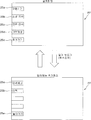
도 26에 나타내는 바와 같이, 본 실시형태에서는, 상세 표시 화면(AA)의 기본 정보 표시 영역(bb)과, 카메라 화상 표시 화면(CC)의 기본 정보 표시 영역(bb) 및 카메라 화상 표시 영역(dd)을 확대 조작 유효 영역으로 하고 있고, 예를 들면, 상세 표시 화면(AA)의 기본 정보 표시 영역(bb)을 탭 조작하면, 기본 정보군이 확대 표시되는 심플 표시 화면(BB)으로 전환되고, 심플 표시 화면(BB)(확대 돌아가기 조작 유효 영역)을 재차 탭 조작하면, 상세 표시 화면(AA)으로 돌아간다. 또한, 카메라 화상 표시 화면(CC)의 기본 정보 표시 영역(bb)을 탭 조작하면, 기본 정보군이 확대 표시되는 심플 표시 화면(BB)으로 전환되고, 심플 표시 화면(BB)을 재차 탭 조작하면, 카메라 화상 표시 화면(CC)으로 돌아간다. 또한, 카메라 화상 표시 화면(CC)의 카메라 화상 표시 영역(dd)을 탭 조작하면, 카메라 화상이 확대 표시되는 카메라 화상 확대 표시 화면(DD)으로 전환되고, 카메라 화상 확대 표시 화면(DD)(확대 돌아가기 조작 유효 영역)을 재차 탭 조작하면, 카메라 화상 표시 화면(CC)으로 돌아간다. 26, in this embodiment, the basic information display area bb of the detailed display screen AA, the basic information display area bb of the camera image display screen CC, and the camera image display area dd For example, when the basic information display area bb of the detailed display screen AA is tapped, the basic information group is switched to the simple display screen BB that is enlarged and displayed, When the simple display screen BB (enlarged return operation effective area) is tapped again, the screen returns to the detailed display screen AA. When the basic information display area bb of the camera image display screen CC is tapped, the basic information group is switched to the simple display screen BB to be enlarged. When the simple display screen BB is tapped again , And returns to the camera image display screen (CC). When the camera image display area dd of the camera image display screen CC is tapped, the camera image is switched to the camera image enlargement display screen DD to be enlarged and displayed, and the camera image enlargement display screen DD Return operation area) is tapped again, the screen returns to the camera image display screen (CC).
다음에, 액정 표시부(14)의 표시 동작(초기 표시, 이상 표시, 딜러 메뉴 표시 및 에러 이력 표시)에 대해서, 도 27 ~ 도 31을 참조하여 설명한다. Next, display operations (initial display, abnormal display, dealer menu display, and error history display) of the liquid
액정 표시부(14)는, 작업 화면인 상세 표시 화면(AA), 심플 표시 화면(BB) 및 카메라 화상 표시 화면(CC)을 전환 조작 가능한 상태로 표시하는 것에 있어서, 키 스위치(SW)가 ON 조작되었을 때, 이전회의 작업시에 마지막에 표시한 작업 화면을 초기 화면으로서 표시시킨다. 예를 들면, 카메라 화상 표시 화면(CC)을 표시시킨 상태에서 키 스위치(SW)를 OFF 조작했을 경우, 다음회의 키 스위치(SW)가 ON 조작되었을 때, 카메라 화상 표시 화면(CC)이 초기 화면으로서 표시된다. 또한, 본 실시형태에서는, 카메라 화상 확대 표시 화면(DD)을 표시시킨 상태에서 키 스위치(SW)를 OFF 조작했을 경우, 다음회의 키 스위치(SW)가 ON 조작되었을 때, 카메라 화상 표시 화면(CC)이 초기 화면으로서 표시되는데, 카메라 화상 확대 표시 화면(DD)이 초기 화면으로서 표시되도록 해도 좋다. The liquid
또한, 액정 표시부(14)에 설정 화면(EE)이 표시된 상태에서 키 스위치(SW)가 OFF 조작되었을 경우는, 다음회의 키 스위치(SW)가 ON 조작되었을 때, 설정 화면(EE)이 아니라, 이전회의 작업시에 마지막에 표시한 작업 화면을 초기 화면으로서 표시시킨다. 예를 들면, 상세 표시 화면(AA)으로부터 설정 화면(EE)으로 이행하고, 설정 화면(EE)의 표시 상태에서 키 스위치(SW)가 OFF 조작되었을 경우는, 다음회의 키 스위치(SW)가 ON 조작되었을 때, 상세 표시 화면(AA)이 초기 화면으로서 표시된다. When the key switch SW is turned off in the state that the setting screen EE is displayed on the liquid
도 27 및 도 28에 나타내는 바와 같이, 액정 표시부(14)는, 기체의 이상 상태를 표시하는 이상 통지를 행한다. 통지하는 이상 항목에는, 이상의 발생에 따라서 경보가 행해지는 경보 항목과, 이상의 발생에 따라서 엔진이 정지되는 엔진 정지 항목이 포함되어 있다. 예를 들면, 경보 항목으로서는, 엔진 과부하 경보, 엔진 오일 부족 경보, 배터리 전압 이상 경보, 선별 과부하 경보, 1번 나선, 2번 나선 과부하 경보, 에어크리너 이상 경보, DPF 경보, 엔진 냉각수온 이상 경보, 노터(knotter) 끈 떨어짐 경보, 그레인 탱크 풀(full) 경보 등이 있고, 엔진 정지 항목으로서는, 전처리부 막힘, 1번 나선, 2번 나선 막힘, 배출 짚 막힘, 결속기 막힘, 그레인 탱크 오버플로우, 엔진 정지 스위치 조작 등이 있다. 27 and 28, the liquid
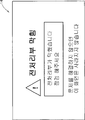
도 27에 나타내는 바와 같이, 경보 항목에 관한 이상 통지는, 표시 중의 화면 상과 중첩되는 팝업 윈도우에 의해 표시된다. 예를 들면, 도 27에 나타내는 경보 항목에 관한 이상 통지는, 배터리 전압 이상 경보이며, 이상 내용을 나타내는 「배터리 충전 부족입니다.」라고 하는 메세지와 이상에 대한 대처 방법을 나타내는 「알터네이터의 벨트를 점검해 주세요.」라고 하는 메세지가 포함되어 있다. 덧붙여서, 경보 항목에 관한 이상 통지 화면의 배경은, 「황색」 등의 주의를 환기할 수 있는 색을 선택하는 것이 바람직하다. As shown in Fig. 27, the abnormality notification relating to the alarm item is displayed by a pop-up window overlapping with the displayed screen. For example, the abnormality notification relating to the alarm item shown in Fig. 27 is an alarm of battery voltage abnormality, and a message " Battery is insufficient to charge " Please give me a message. " Incidentally, it is preferable to select a color that is capable of drawing attention such as " yellow " in the background of the abnormality notification screen concerning the alarm item.
도 20 ~ 도 23, 도 27에 나타내는 바와 같이, 경보 항목에 관한 이상 통지는, 인위 조작에 대응한 확대 표시와 축소 표시와의 표시 전환이 가능하게 되어 있다. 즉, 이상 경보의 표시 당초는, 도 27에 나타내는 확대 표시에서 이상 상태에 대한 주의를 환기하지만, 경보 항목에 관한 이상 상태는, 발생해도 작업의 계속이 가능하기 때문에, 그대로 작업을 계속하는 경우는, 이상 통지를 축소 표시로 하는 것으로, 작업 화면의 표시를 우선시킬 수 있다. 본 실시형태에서는, 도 27에 나타내는 이상 표시 영역을 탭 조작하면, 도 20 ~ 도 23에 나타내는 바와 같이, 이상 표시가 화면 하부에 축소 표시된다. 축소 표시에서는, 이상에 대한 대처 방법은 표시되지 않고, 이상 내용만이 표시된다. 또한, 축소 표시된 이상 표시 영역을 탭 조작하면, 도 27에 나타내는 확대된 이상 표시로 전환된다. 덧붙여서, 이상 표시를 축소 표시하면, 주의 환기 효과가 저하되므로, 축소된 이상 표시의 배경은, 「황색」보다 주의 환기 효과가 높은 「적색」 등을 선택하는 것이 바람직하다. As shown in Figs. 20 to 23 and Fig. 27, the abnormality related to the alarm item can be switched between the enlarged display and the reduced display corresponding to the artificial operation. In other words, although the alarm at the beginning of the display of the abnormal alarm warns the operator of the abnormal state in the enlarged display shown in Fig. 27, since the abnormal state relating to the alarm item can be continued even if the alarm condition occurs, , It is possible to prioritize the display of the work screen by making the abnormality notification a reduced display. In the present embodiment, when the abnormal display area shown in Fig. 27 is tapped, the abnormal display is displayed at the lower part of the screen as shown in Fig. 20 to Fig. In the reduced display, the countermeasure against the abnormality is not displayed but only the abnormality is displayed. Further, when the reduced display area is tapped, the expanded abnormal display shown in Fig. 27 is switched. Incidentally, when the abnormality display is reduced and displayed, the effect of ventilation of the state is lowered. Therefore, it is preferable to select "red" or the like with a higher ventilation effect than "yellow" as the background of the reduced abnormality display.
도 28에 나타내는 바와 같이, 엔진 정지 항목에 관한 이상 표시는, 표시 중의 화면을 전환하여 전체화면으로 표시된다. 예를 들면, 도 28에 나타내는 엔진 정지 항목에 관한 이상 통지는, 전처리부 막힘이며, 이상 내용을 나타내는 「전처리부 막힘」이라고 하는 메세지와, 이상에 대한 대처 방법을 나타내는 「전처리부가 막혔으므로 검사해 주세요」라고 하는 메세지와, 「문제를 해결하지 않으면 이 화면은 사라지지 않습니다」라고 하는 메세지가 포함되어 있다. 덧붙여서, 엔진 정지 항목에 관한 이상 통지 화면의 배경은, 「황색」(경보 항목에 관한 확대 이상 표시의 배경색)보다 주의 환기 효과가 높은 「적색」을 선택하는 것이 바람직하다. As shown in Fig. 28, the abnormal display relating to the engine stop item is displayed as a full screen by switching the screen during display. For example, the abnormality notification relating to the engine stop item shown in Fig. 28 is a message indicating that the preprocessing section is clogged, and the message " pre-processing section clogging " "And" this screen does not disappear unless the problem is solved "is included. Incidentally, it is preferable that the background of the abnormality notification screen related to the engine stop item is "red" which has a higher ventilation effect than "yellow" (the background color of the enlargement / anomaly display related to the alarm item).
엔진 정지 항목에 관한 이상 표시는, 인위 조작에 대응한 표시 전환이 불가능해져 있고, 이상 원인이 해소될 때까지 표시가 계속된다. 한편, 경보 항목에 관한 이상 표시는, 인위 조작에 대응한 축소 표시로의 전환이 가능하고, 이 상태에서 작업을 계속하는 것이 가능하지만, 경보 항목에 관한 이상 표시(확대 표시 및 축소 표시를 포함함)도, 이상 원인이 해소될 때까지 표시가 계속되므로, 이상에 대한 확실한 대응을 촉진할 수 있다. In the abnormal display of the engine stop item, the display switching is not possible in response to the artificial operation, and the display continues until the cause of the abnormality is resolved. On the other hand, the abnormal display regarding the alarm item can be switched to the reduced display corresponding to the artificial operation, and the operation can be continued in this state. However, the abnormal display (including the enlarged display and the reduced display) ), The display continues until the cause of the problem is solved, so that it is possible to promote a reliable response to the abnormality.
복수의 이상 항목이 발생하고 있는 상황에서는, 이들의 이상 통지를 동시에 실행하는 것이 불가능하기 때문에, 미리 우선 순위를 정하고 있다. 예를 들면, 경보 항목보다 엔진 정지 항목의 이상을 우선함과 함께, 엔진 정지 항목에 포함되는 복수의 이상 종별에 대해서 우선 순위를 정하고, 또한, 경보 항목에 포함되는 복수의 이상 종별에 대해서도 우선 순위를 정하고 있다. 그리고, 복수의 이상 항목이 발생했을 경우는, 미리 정해진 우선 순위에 따라, 우선 순위가 높은 이상 항목으로부터 이상 표시를 행한다. In a situation where a plurality of anomalous items occur, it is impossible to simultaneously execute these anomalous notifications, so that priority is given in advance. For example, the abnormality of the engine stop item is given priority over the alarm item, the priority order is set for the plurality of abnormal types included in the engine stop item, and also, for the plurality of abnormal types included in the alarm item, . When a plurality of anomalous items occur, anomalous display is performed from an item having a higher priority in accordance with a predetermined priority order.
도 29에 나타내는 바와 같이, 액정 표시부(14)에서는, 주로 딜러의 서비스 맨이 이용하는 딜러 메뉴 화면(FF)을 표시시킬 수 있다. 딜러 메뉴 화면(FF)으로의 이행은, 예를 들면, 설정 화면(EE)에 있어서, 미리 결정된 1 또는 복수의 터치 조작 버튼(25a ~ 25e)을 길게 누르는 조작을 하는 것으로써 행해진다. As shown in Fig. 29, the liquid
도 30에 나타내는 바와 같이, 딜러 메뉴 화면(FF)에서는, 터치 조작 버튼(25a, 25b, 25e)의 버튼 명칭으로서 각각 「입력 체크」, 「이력」, 「돌아가기」가 부가되어 있다. 터치 조작 버튼(25a)을 탭 조작하면, 도시하지 않는 입력 체크 화면이 표시되고, 터치 조작 버튼(25b)을 탭 조작하면, 도 19에 나타내는 에러 이력 화면(GG)이 표시되고, 터치 조작 버튼(25e)를 탭 조작하면, 설정 화면(EE)으로 돌아간다. 덧붙여서, 입력 체크 화면은, 센서 등의 신호 입력을 체크하기 위한 화면이며, 예를 들면, 체크하고 싶은 부품의 조작에 따라서, 표시 제어부(24)에 정상적인 신호가 입력되었을 경우, 그것을 부저음으로 통지한다. 본 실시형태에서는, 입력 체크 화면을 특수 모드로서 취급한다. 특수 모드는, 일단 이행하면, 이전의 화면으로 돌아오는 것이 규제되는 제어 상태를 의미하고, 엔진이 정지할 때까지 그 화면 표시가 유지된다. As shown in Fig. 30, in the dealer menu screen FF, "input check", "history" and "return" are added as button names of the
도 31에 나타내는 바와 같이, 에러 이력 화면(GG)에서는, 에러 이력 번호(예를 들면, 에러 이력 01), 에러 발생 시간(예를 들면, 아워 미터(hour meter) 8888.8) 및 에러 내용(예를 들면, 전처리 막힘(엔진 정지))으로 특정되는 복수의 에러 이력이, 시계열로 상하 방향으로 나열되어 표시된다. 에러 이력 화면(GG)에 표시되는 에러 이력에는, 전장 부품계 에러 이력으로서 기억된 전장 부품의 이상에 관한 에러 정보와, 기체 상태계 에러 이력으로서 기억된 기체 상태의 이상에 관한 에러 정보가 포함되어 있고, 전장 부품계 에러 이력 및 기체 상태계 에러 이력이 시계열로 일원적(一元的)으로 표시된다. 이러한 에러 이력 표시에 의하면, 전장 부품계 에러의 발생 원인을 그 이전의 기체 상태계 에러 이력에 기초하여 구명하는 것이 가능하게 된다. 예를 들면, 전처리 막힘이 2회 발생한 후에, 전처리 리프트 포텐셔 에러가 발생하고 있는 경우, 전처리 막힘에 기인하는 전처리 리프트 포텐셔의 이상으로 생각되므로, 단순하게 전처리 리프트 포텐셔를 교환할 뿐만 아니라, 그 주변의 파손의 유무의 확인이 필요한 것을 이해할 수 있다. 31, in the error history screen GG, an error history number (for example, an error history 01), an error occurrence time (for example, an hour meter 8888.8) , A plurality of error histories, which are specified by the pre-processing clogging (engine stop), are displayed in a time-sequential order in the vertical direction. The error history displayed on the error history screen GG includes error information on abnormality of the electrical component stored as the electrical component system error history and error information on the abnormality of the gaseous state stored as the gaseous state error history And the history of the electrical part system error history and the gaseous state error history are displayed in a time series in a one-dimensional manner. According to such an error history display, it is possible to determine the cause of the electric component part system error based on the previous gas state system error history. For example, if a pretreatment lift potentiometer error occurs after two pretreatment clogs, it is considered to be an abnormality of the pretreatment lift potentiometer due to the clogging of the pretreatment, so that not only the pretreatment lift potentiometer is simply replaced, It can be understood that it is necessary to check whether or not the periphery thereof is damaged.
도 31에는, 기체 상태계 에러 이력으로서 표시되는 기체 상태계 에러의 항목으로서, 에러의 발생에 따라서 엔진이 정지되는 상술한 엔진 정지 에러 항목의 막힘, 전처리 막힘을 예시하고 있는데, 그 외의 엔진 정지 에러 항목이 포함되는 것은 말할 필요도 없다. 또한, 기체 상태계 에러 이력으로서 표시되는 기체 상태계 에러의 항목으로서, 에러의 발생에 따라서 경보를 하는 상술한 경보 에러 항목을 포함하도록 해도 좋다. 이와 같이 하면, 예를 들면, 전동 벨트가 파손되어 교환하는 경우에, 에러 이력으로서 선별이나 나선의 과부하 경보 이력이 남아 있으면, 오퍼레이터의 기계의 사용 방법에 원인이 있다고 추정하는 것이 가능하게 된다. 31 shows the clogging of the engine stop error items and the clogging of the pre-processing closure, in which the engine is stopped in response to the occurrence of an error, as an item of the gaseous system error indicated as the gaseous state error history, Needless to say, items are included. The gaseous state error indicated as the gaseous state error history may also include the above-mentioned alarm error item for generating an alarm in response to the occurrence of an error. This makes it possible to estimate that there is a cause for the use of the machine by the operator when, for example, the transmission belt is broken and replaced, and the selection history or the spiral overload warning history remains as the error history.
에러 이력 화면(GG)에서는, 에러의 종별에 따라서 에러 이력의 표시색을 상이하게 하는 것이 바람직하다. 예를 들면, 전장 부품계 에러 이력을 「황색」, 기체 상태계 에러 이력을 「적색」으로 표시시킨다. 이와 같이 하면, 표시색에 기초하여 에러의 종별을 식별할 수 있으므로, 에러의 원인 구명이 용이하게 된다. In the error history screen GG, it is preferable to make the display color of the error history different according to the type of error. For example, the electric component part error history is indicated as "yellow" and the gas state error history is indicated as "red". In this manner, the type of error can be identified based on the display color, thereby facilitating the search for the cause of the error.
다음에, 상기와 같은 액정 표시부(14)의 화면 전환 조작 및 표시 동작을 실현하는 표시 제어부(24)의 제어 순서에 대해서, 도 32 ~ 도 35를 참조하여 설명한다. Next, the control procedure of the
표시 제어부(24)는, 하드웨어와 소프트웨어와의 협동에 의해 실현되는 기능적인 구성으로서, 초기 표시 제어 수단, 확대 표시 수단, 이상 통지 수단 및 에러 이력 표시 수단을 구비하고 있고, 이하, 초기 표시 제어 수단을 실현하는 초기 표시 제어와, 확대 표시 수단을 실현하는 화면 표시 전환 제어와, 이상 통지 수단을 실현하는 이상 통지 제어와, 에러 이력 표시 수단을 실현하는 에러 이력 표시 제어의 구체적인 제어 순서를 설명한다. The
도 32에 나타내는 바와 같이, 초기 표시 제어에서는, 우선, 엔진이 정지 상태인지 아닌지를 판단함과 함께(S11), 키 스위치(SW)의 ON 조작을 판단하고(S12), 여기서 양 판단의 결과가 모두 YES인 경우는, 기억 화면의 유무를 판단한다(S13). 이 판단 결과가 없음인 경우는, 작업 화면인 상세 표시 화면(A), 심플 표시 화면(B) 및 카메라 화상 표시 화면(C) 중, 미리 정해진 디폴트 작업 화면(예를 들면, 상세 표시 화면)을 액정 표시부(14)에 표시시키는 한편(S14), 기억 화면이 있다고 판단했을 경우는, 기억하고 있는 작업 화면을 액정 표시부(14)에 표시시킨다(S15). 계속하여, 화면 표시 전환 제어(S16), 이상 통지 제어(S17), 에러 이력 표시 제어(S18) 등의 서브루틴을 실행한 후, 현재의 표시 화면이 작업 화면인지 그 이외의 화면인지를 판단한다(S19). 여기서 작업 화면이라고 판단했을 경우는, 현재 표시하고 있는 작업 화면의 종별을 기억(기억 화면의 리라이트(rewrite))하는 한편(S20), 작업 화면 이외라고 판단했을 경우는, 그대로 상위 루틴으로 복귀한다. 이것에 의해, 키 스위치(SW)가 ON 조작되었을 때, 이전회의 작업시에 마지막으로 표시한 작업 화면을 초기 화면으로서 표시시키는 것이 가능하게 된다. As shown in Fig. 32, in the initial display control, first, it is judged whether the engine is in the stop state or not (S11), the ON operation of the key switch SW is judged (S12) If all are YES, the presence or absence of a storage screen is determined (S13). If the determination result is NO, a predetermined default operation screen (for example, a detailed display screen) among the detailed display screen A, the simple display screen B, and the camera image display screen C, (S14). If it is determined that there is a storage screen, the stored operation screen is displayed on the liquid crystal display unit 14 (S15). Subsequently, after executing the subroutine such as the screen display switching control (S16), the abnormality notification control (S17), and the error history display control (S18), it is determined whether the current display screen is a work screen or other screen (S19). If it is determined that the work screen is the work screen, the type of the work screen currently displayed is rewritten (S205), and if it is determined that the work screen is not the work screen, . Thus, when the key switch SW is turned ON, it is possible to display the work screen finally displayed at the previous meeting work as an initial screen.
도 33에 나타내는 바와 같이, 화면 표시 전환 제어에서는, 물리적 조작 버튼(26a ~ 26e)의 조작 및 액정 표시부(14)의 터치 조작(탭 조작 및 플릭 조작)을 판단한다(S31, S33, S40). 물리적 조작 버튼(26a ~ 26e)이 조작되었다고 판단했을 경우는, 조작된 물리적 조작 버튼(26a ~ 26e)에 대응하는 화면을 액정 표시부(14)에 표시시킨다(S32). 또한, 액정 표시부(14)가 탭 조작되었다고 판단했을 경우는, 탭 조작 위치가 터치 조작 버튼(25a ~ 25e)인지 아닌지(S34), 확대 조작 유효 영역인지 아닌지(S35), 확대 돌아가기 조작 유효 영역(S36)인지 아닌지를 판단한다. 여기서, 탭 조작 위치가 터치 조작 버튼(25a ~ 25e)이라고 판단했을 경우는, 탭 조작된 터치 조작 버튼(25a ~ 25e)에 대응하는 화면을 액정 표시부(14)에 표시시키고(S37), 탭 조작 위치가 확대 조작 유효 영역이라고 판단했을 경우는, 탭 조작된 확대 조작 유효 영역에 대응하는 화면을 액정 표시부(14)에 표시시키고(S38), 탭 조작 위치가 확대 돌아가기 조작 유효 영역이라고 판단했을 경우는, 탭 조작된 확대 돌아가기 조작 유효 영역에 대응하는 화면을 액정 표시부(14)에 표시시킨다(S39). 또한, 액정 표시부(14)가 플릭 조작되었다고 판단했을 경우는, 플릭 조작 위치가 플릭 조작 유효 영역인지 아닌지를 판단하고(S41), 이 판단 결과가 YES의 경우는, 플릭 조작된 플릭 조작 유효 영역 및 플릭 조작 방향에 대응하는 화면을 액정 표시부(14)에 표시시킨다(S42). As shown in Fig. 33, in the screen display switching control, the operation of the
도 34에 나타내는 바와 같이, 이상 통지 제어에서는, 우선, 이상 상태가 발생했는지 아닌지를 판단하고(S51), 이 판단 결과가 NO인 경우는, 이상 표시를 클리어함과 함께(S52), 이상 표시의 확대·축소를 전환하기 위한 플래그 F에 초기치인 「0」(확대 표시)을 세트한다(S53). 한편, 이상 상태가 발생하고 있다고 판단했을 경우는, 우선 순위 처리를 실행한다(S54). 이 우선 순위 처리는, 복수의 이상 상태가 발생하고 있는 상황에 있어서, 미리 정해진 우선 순위에 따라, 우선적으로 이상 표시를 행하는 이상 항목을 추출하는 처리이다. 다음에, 추출한 이상 항목이 「엔진 정지 항목」, 「경보 항목」의 어느 하나에 속하는지를 판단하고(S55), 이 판단 결과가 「엔진 정지 항목」인 경우는, 상기 이상 항목에 관한 이상 표시를 액정 표시부(14)에 전체화면 표시한다(S56). 한편, 「경보 항목」에 관한 이상 항목이라고 판단했을 경우는, 플래그 F를 참조하고(S57), 여기서 플래그 F가 「0」이라고 판단했을 경우는, 상기 이상 항목에 관한 이상 표시를 액정 표시부(14)에 팝업 윈도우로서 확대 표시시킨다(S58). 그 후, 확대 표시 영역의 탭 조작을 판단함과 함께 (S59), 상기 판단 결과가 YES의 경우는, 플래그 F에 「1」을 세트한다(S60). 또한, 스텝 S57의 판단 결과가 「1」인 경우는, 상기 이상 항목에 관한 이상 표시를 액정 표시부(14)에 축소 표시시킨다(S61). 그 후, 축소 표시 영역의 탭 조작을 판단함과 함께(S62), 상기 판단 결과가 YES의 경우는, 플래그 F에 「0」을 세트한다(S63). As shown in Fig. 34, in the abnormality notification control, first, it is judged whether or not an abnormal state has occurred (S51). If the judgment result is NO, the abnormality display is cleared (S52) Quot; 0 " (enlarged display) which is the initial value is set to the flag F for switching the enlargement / reduction (S53). On the other hand, when it is judged that an abnormal state is occurring, priority order processing is executed (S54). This priority process is a process for extracting an abnormal item to which abnormality display is preferentially performed according to a predetermined priority in a situation where a plurality of abnormal conditions are occurring. Next, it is judged whether or not the extracted abnormal item belongs to "engine stop item" or "alarm item" (S55). If the judgment result is "engine stop item" And displays it on the liquid
도 35에 나타내는 바와 같이, 에러 이력 표시 제어에서는, 우선, 서브루틴인 전장 부품계 에러 이력 기억 처리(S71)와 기체 상태계 에러 이력 기억 처리(S72)를 실행한다. 전장 부품계 에러 이력 기억 처리는, 전장 부품의 에러가 발생했을 경우에, 그 에러 종별을 발생 시간 정보(아워 미터값)와 함께 에러 이력 데이타베이스에 기억하는 처리이며, 기체 상태계 에러 이력 기억 처리는, 기체 상태의 에러가 발생했을 경우에, 그 에러 종별을 발생 시간 정보와 함께 에러 이력 데이타베이스에 기억하는 처리이다. 다음에, 에러 이력 표시 화면의 표시 조작을 판단하고(S73), 상기 판단 결과가 YES인 경우는, 에러 이력 데이타베이스에 기억된 전장 부품계 에러 이력 및 기체 상태계 에러 이력을 액정 표시부(14)에 시계열로 일원(一元) 표시시킨다(S74). 이 때, 전장 부품계 에러 이력과 기체 상태계 에러 이력은 다른 색으로 표시된다. As shown in Fig. 35, in the error history display control, first, the electrical component part system error history storage process S71 and the gas state system error history storage process S72, which are subroutines, are executed. The electrical component part system error history storage processing is processing for storing the error type in the error history database together with the generation time information (hour meter value) when an error of the electrical component occurs, and the gas state system error history storage processing Is a process in which, when a gaseous error occurs, the error type is stored in the error history database together with the occurrence time information. Next, the display operation of the error history display screen is determined (S73). If the result of the determination is YES, the electric component system error history and the gaseous state error history stored in the error history database are displayed on the liquid
상술한 것과 같이 구성된 제2 실시형태에 의하면, 표시 제어부(24)는, 작업시에 필요한 정보를 표시하는 복수 종류의 작업 화면(AA ~ CC)을 전환 조작 가능한 상태로 액정 표시부(14)에 표시하는 것에 있어서, 키 스위치(SW)가 ON 조작되었을 때, 이전회의 작업시에 마지막으로 표시한 작업 화면(AA ~ CC)을 액정 표시부(14)에 표시시키므로, 키 스위치(SW)의 ON 조작 후, 일일이 원하는 작업 화면(AA ~ CC)으로 전환하는 수고가 불필요해진다. According to the second embodiment configured as described above, the
또한, 복수 종류의 작업 화면(AA ~ CC)에는, 심플 표시 화면(BB)(제1 작업 화면)과, 상세 표시 화면(AA)(제2 작업 화면)과, 카메라 화상 표시 화면(CC)(제3 작업 화면)이 포함되고, 심플 표시 화면(BB)은, 중요도가 높은 기본 정보를 표시하고, 상세 표시 화면(AA)은, 기본 정보와 상기 기본 정보보다 중요도가 낮은 부속 정보를 표시하고, 카메라 화상 표시 화면(CC)은, 기본 정보와 기체에 설치된 카메라의 화상을 표시하므로, 어느 작업 화면(AA ~ CC)을 선택해도, 중요도가 높은 기본 정보의 표시를 유지하고, 기본 정보의 결여에 의해서 작업에 지장을 초래하는 것을 방지할 수 있다. A plurality of kinds of work screens AA to CC are provided with a simple display screen BB (first operation screen), a detailed display screen AA (second operation screen), a camera image display screen CC The simple display screen BB displays basic information with high importance and the detailed display screen AA displays basic information and accessory information having lower importance than the basic information, Since the camera image display screen (CC) displays the basic information and the image of the camera installed in the base, it is possible to maintain the display of the basic information with high importance even if any work screen (AA to CC) It is possible to prevent the work from being hindered.
또한, 본 실시형태의 표시 제어부(24)는, 각 작업 화면(AA ~ CC)으로부터 설정 화면(EE)으로의 이행, 및, 설정 화면(EE)으로부터 각 작업 화면(AA ~ CC)으로의 이행을 허용하고, 액정 표시부(14)에 설정 화면(EE)이 표시된 상태에서 키 스위치(SW)가 OFF 조작되었을 경우, 다음회의 키 스위치(SW)가 ON 조작되었을 때, 설정 화면(EE)이 아니라, 이전회의 작업시에 마지막으로 표시한 작업 화면(AA ~ CC)을 액정 표시부(14)에 표시시키므로, 키 스위치(SW)의 ON 조작 후, 일일이 설정 화면(EE)으로부터 원하는 작업 화면(AA ~ CC)으로 전환하는 수고가 불필요해진다. The
이하에, 우선권 주장의 기초로 한 출원의 원서에 최초로 첨부한 특허 청구의 범위에 기재한 발명을 부기한다. Hereinafter, the invention described in the scope of claims appended hereto to the application of the application based on the priority claim shall be added.
[일본 특허출원 2014-220085][Japanese Patent Application 2014-220085]
<청구항 1><Claim 1>
주행 장치를 하부에 구비한 기체에 예취부와 탈곡부를 마련하고, 기체에 탑재한 엔진의 동력에 의해서 이것들을 구동함과 함께, 기체 각 부의 작동을 조종부에 마련한 조작 도구에 의해서 제어하여 예취 탈곡 작업을 행하는 콤바인에 있어서, 상기 조종부에 마련한 운전석의 전방으로부터 1측방에 걸쳐서 조작 박스를 세워 설치하고, 상기 조작 박스의 전부(前部)측에 액정 모니터를 중앙으로 하여, 그 좌우측에 기체의 선회나 예취부의 승강을 행하는 조작 도구와 예취 탈곡 작업 중에 사용하는 조작 도구군을 배분하여 마련함과 함께, 상기 조작 도구군의 후방이 되는 조작 박스의 측부측에 기체의 주행 변속을 행하는 조작 도구를 마련하고, 또한, 상기 조작 도구군 중, 조작 빈도가 높은 조작 도구를 가장 운전석에 가까운 액정 모니터 측에 배치하는 것을 특징으로 하는 콤바인. And a control unit for controlling the operation of the gas angle unit by an operation tool provided on the control unit so as to control the machining operation of the machining center, The operation box is provided with a control box extending from one side of the driver's seat to one side of the driver's seat provided on the control unit. A liquid crystal monitor is disposed at the front side of the control box, An operating tool for performing an up-and-down movement of the turning or preloading portion and an operating tool group for use during the cutting and draining operation are distributed and provided, and an operation tool for performing a running shift of the vehicle on the side of the operation box behind the operating tool group Further, it is also possible to arrange, on the liquid crystal monitor side closest to the driver's seat, an operation tool having a high operation frequency Combine according to claim.
<청구항 2><Claim 2>
상기 가장 운전석에 가까운 액정 모니터 측에 배치하는 조작 도구를, 예취 클러치와 탈곡 클러치를 단속하는 조작 도구와, 엔진 회전수를 설정하는 조작 도구로 구성한 것을 특징으로 하는 청구항 1에 기재된 콤바인. The combine according to
<청구항 3><Claim 3>
상기 조작 도구군 중, 자동 제어를 ON OFF 하는 스위치로 구성하는 조작 도구를, 기체의 주행 변속을 행하는 조작 도구의 전부(前部)측에 배치하고, 다이얼이나 레버 스위치로 구성하는 조작 도구는, 가장 운전석에서 먼 측에 배치하는 것을 특징으로 하는 청구항 2에 기재된 콤바인. An operating tool constituted by a dial or a lever switch is disposed on the front side of an operating tool for performing a shift operation of the vehicle, The combine according to
[일본 특허출원 2014-220086][Japanese Patent Application 2014-220086]
<청구항 1><Claim 1>
주행 장치를 하부에 구비한 기체에 예취부와 탈곡부를 마련하고, 기체에 탑재한 엔진의 동력에 의해서 이것들을 구동함과 함께, 기체 각 부의 작동을 조종부에 마련한 조작 도구에 의해서 제어하여 예취 탈곡 작업을 행하는 콤바인에 있어서, 상기 조작 도구를 운전석의 전방으로부터 1측방에 걸쳐서 세워 설치한 조작 박스에 배치함에 있어서, 상기 조작 박스의 전부(前部)측에는, 기체의 선회나 예취부의 승강을 행하는 조작 도구를 마련하는 한편, 조작 박스의 측부측에는, 예취 탈곡 작업 중의 조작 빈도가 높은 제1의 조작 도구군과, 기체의 주행 변속을 행하는 조작 도구와 예취 탈곡 작업 중의 조작 빈도가 낮은 제2 조작 도구군을 전후 방향으로 하여, 그 순서로 배치하는 것을 특징으로 하는 콤바인. And a control unit for controlling the operation of the gas angle unit by an operation tool provided on the control unit so as to control the machining operation of the machining center, A combination combiner for performing an operation in which, when disposing the operating tool in an operation box installed upright from one side of the driver's seat to one side, the front portion of the operation box is provided with a guide A first operating tool group having a high operating frequency during the cutting operation and a second operating tool having a low operating frequency during the pre-scraping operation, And the groups are arranged in the forward and backward directions in that order.
<청구항 2><Claim 2>
상기 제1의 조작 도구군은, 예취 클러치와 탈곡 클러치를 단속하는 조작 도구와, 엔진 회전수를 설정하는 조작 도구와, 탈곡 깊이 자동 제어를 ON OFF 하는 조작 도구와, 기체를 경사시키는 조작 도구와, 예취부의 하강 위치를 설정하는 조작 도구로 구성하는 것을 특징으로 하는 청구항 1에 기재된 콤바인. The first operating tool group includes an operating tool for interrupting the cutting clutch and the descending clutch, an operating tool for setting the engine speed, an operating tool for turning on and off automatic threshing depth control, an operating tool for tilting the gas, And an operating tool for setting a descent position of the preliminary mounting portion.
<청구항 3><Claim 3>
상기 제1의 조작 도구군은, 조작 박스의 측부측의 전부(前部)에 마련한 스위치 케이스에 일괄하여 설치하고, 상기 예취 클러치와 탈곡 클러치를 단속하는 조작 도구와, 엔진 회전수를 설정하는 조작 도구는, 스위치 케이스의 가장 운전석에 가까운 우측쪽에 배치하는 것을 특징으로 하는 청구항 2에 기재된 콤바인. Wherein the first operating tool group is provided collectively in a switch case provided at a front portion on a side of a side of the operation box and includes an operation tool for interrupting the cutting clutch and the descending clutch, The combine according to
[일본 특허출원 2014-220190][Japanese Patent Application 2014-220190]
<청구항 1><Claim 1>
오퍼레이터의 한쪽의 손으로 조작되고, 상기 조작에 따라서 기체의 방향을 변화시키는 조향 조작 도구와,A steering operation tool operated by one hand of the operator and changing the direction of the gas in accordance with the operation;
상기 조향 조작 도구의 측방에 배치되고, 오퍼레이터의 다른쪽의 손으로 조작 가능한 터치 패널식의 액정 표시부와,A touch panel type liquid crystal display part disposed on the side of the steering operation tool and operable by the other hand of the operator,
상기 액정 표시부의 표시를 제어하는 표시 제어부를 구비하고, And a display control unit for controlling the display of the liquid crystal display unit,
상기 표시 제어부는, 상기 액정 표시부의 표시 내용을 전환 조작 가능한 복수의 터치 조작 버튼을 상기 액정 표시부에 표시시킴에 있어서, 상기 액정 표시부의 좌우 단부 중, 상기 조향 조작 도구와는 반대측의 단부에 상기 복수의 터치 조작 버튼을 세로 배열 형상으로 표시시키는 것을 특징으로 하는 작업용 주행차. Wherein the display control unit displays on the liquid crystal display unit a plurality of touch operation buttons capable of switching display contents of the liquid crystal display unit, And the touch operation buttons of the operation button are displayed in a vertical arrangement.
<청구항 2><Claim 2>
상기 액정 표시부의 인접 위치에, 상기 복수의 터치 조작 버튼과 병렬 형상으로 인접하는 복수의 물리적 조작 버튼을 배치하고,A plurality of physical operation buttons adjacent to each other in parallel with the plurality of touch operation buttons are disposed at a position adjacent to the liquid crystal display,
상기 표시 제어부는, 상기 물리적 조작 버튼이 조작되었을 때, 상기 조작된 물리적 조작 버튼에 인접하는 터치 조작 버튼이 터치 조작되었을 경우와 마찬가지로 상기 액정 표시부의 표시 내용을 전환하는 것을 특징으로 하는 청구항 1에 기재된 작업용 주행차. The display control unit switches the display contents of the liquid crystal display unit in the same manner as when the touch operation button adjacent to the operated physical operation button is touched when the physical operation button is operated Working vehicle.
<청구항 3><Claim 3>
상기 액정 표시부의 좌우 측방 중, 상기 조향 조작 도구와는 반대측의 측방에 복수의 설정 조작 도구를 집중 배치한 것을 특징으로 하는 청구항 1 또는 2에 기재된 작업용 주행차. A driving carriage according to any one of
[일본 특허출원 2014-220191][Japanese Patent Application 2014-220191]
<청구항 1><Claim 1>
액정 표시부와, 상기 액정 표시부의 표시를 제어하는 표시 제어부를 구비하는 작업용 주행차로서,A running vehicle for working comprising a liquid crystal display section and a display control section for controlling display of the liquid crystal display section,
상기 표시 제어부는, 상기 액정 표시부의 표시 화면을, 인위적인 화면 전환 조작에 따라서, 디폴트 표시 화면인 통상 표시 화면으로부터, 각종 설정 정보를 표시하는 설정 정보 표시 화면, 및/또는, 카메라 화상을 표시하는 카메라 화상 표시 화면으로의 전환에 있어서,The display control section may display the display screen of the liquid crystal display section on the basis of an artificial screen switching operation from a normal display screen as a default display screen to a setting information display screen for displaying various setting information and / In switching to the image display screen,
상기 통상 표시 화면의 표시 정보를, 중요도가 높은 기본 정보군과, 상기 기본 정보군보다 중요도가 낮은 부속 정보군으로 나누어서 표시함과 함께, 상기 설정 정보 표시 화면 또는 상기 카메라 화상 표시 화면으로의 전환시에, 기본 정보군의 표시를 유지하면서, 부속 정보군 대신에 각종 설정 정보 또는 카메라 화상을 표시시키는 것을 특징으로 하는 작업용 주행차. The display information of the normal display screen is divided into basic information groups of high importance and subsidiary information groups of lower importance than the basic information group and displayed on the setting information display screen or the camera image display screen And displays various setting information or a camera image instead of the associated information group while maintaining the display of the basic information group.
<청구항 2><Claim 2>
상기 표시 제어부는, 상기 액정 표시부의 표시 화면을, 인위적인 화면 전환 조작에 따라서, 상기 카메라 화상 표시 화면으로부터, 다른 카메라 화상을 표시하는 제2의 카메라 화상 표시 화면으로 전환 가능하고,The display control section is capable of switching the display screen of the liquid crystal display section from the camera image display screen to a second camera image display screen displaying another camera image in accordance with an artificial screen switching operation,
상기 제2의 카메라 화상 표시 화면에서는, 기본 정보군의 표시를 유지하면서, 카메라 화상을 다른 카메라 화상으로 전환하는 것을 특징으로 하는 청구항 1에 기재된 작업용 주행차. The traveling carriage according to
<청구항 3><Claim 3>
상기 표시 제어부는, 상기 액정 표시부의 표시 화면을, 인위적인 화면 전환 조작에 따라서, 상기 카메라 화상 표시 화면으로부터, 카메라 화상을 확대 표시하는 카메라 화상 확대 표시 화면으로 전환 가능하고,The display control section can switch the display screen of the liquid crystal display section from the camera image display screen to a camera image enlargement display screen for enlarging and displaying the camera image in accordance with an artificial screen switching operation,
상기 카메라 화상 확대 표시 화면에서는, 기본 정보군의 표시 영역을 축소 또는 생략하여 카메라 화상을 확대 표시시키는 것을 특징으로 하는 청구항 1 또는 2에 기재된 작업용 주행차. The running vehicle for working according to
<청구항 4><Claim 4>
상기 표시 제어부는, 상기 액정 표시부의 표시 화면을, 인위적인 화면 전환 조작에 따라서, 기본 정보군을 확대 표시하는 기본 정보군 확대 표시 화면으로 전환 가능한 것을 특징으로 하는 청구항 1 내지 3의 어느 한 항에 기재된 작업용 주행차. The display control apparatus according to any one of
[일본 특허출원 2014-220192][Japanese Patent Application 2014-220192]
<청구항 1><Claim 1>
액정 표시부와, 상기 액정 표시부의 표시를 제어하는 표시 제어부를 구비하는 작업용 주행차로서,A running vehicle for working comprising a liquid crystal display section and a display control section for controlling display of the liquid crystal display section,
상기 표시 제어부는, 상기 액정 표시부의 표시 화면을, 인위적인 화면 전환 조작에 따라서, 통상 작업시에 필요한 정보를 표시하는 통상 작업 화면과, 메인테넌스에 필요한 정보를 표시하는 메인테넌스 화면으로 전환 가능하게 하는 것에 있어서,The display control section switches the display screen of the liquid crystal display section to a maintenance screen for displaying information necessary for maintenance in accordance with an artificial screen switching operation and a normal operation screen for displaying information necessary for normal operation In doing so,
상기 통상 작업 화면과 상기 메인테넌스 화면의 어느 한 쪽을 선택하는 초기 화면을 표시함과 함께, 이 초기 화면에서 상기 통상 작업 화면이 선택된 후는, 상기 메인테넌스 화면으로의 이행을 규제하는 것을 특징으로 하는 작업용 주행차. The control unit displays an initial screen for selecting either the normal operation screen or the maintenance screen and restricts the transition to the maintenance screen after the normal operation screen is selected on the initial screen Features a running car for work.
<청구항 2><Claim 2>
상기 표시 제어부는, 엔진 정지 상태에서 키 스위치가 ON 되었을 경우에만 상기 초기 화면을 표시시키는 것을 특징으로 하는 청구항 1에 기재된 작업용 주행차. The driving carriage according to
<청구항 3><Claim 3>
상기 표시 제어부는, 상기 초기 화면에서 상기 메인테넌스 화면이 선택되었을 경우, 유저용 메인테넌스 화면과 딜러용 메인테넌스 화면의 어느 한 쪽을 선택하는 메인테넌스 선택 화면을 표시시키는 것을 특징으로 하는 청구항 1 또는 2에 기재된 작업용 주행차. Wherein the display control unit displays a maintenance selection screen for selecting either the maintenance main screen for the user or the maintenance main screen for the dealer when the maintenance screen is selected on the initial screen Wherein the running vehicle is a running vehicle according to
[일본 특허출원 2015-155115][Japanese Patent Application 2015-155115]
<청구항 1><Claim 1>
터치 패널식의 액정 표시부와, 상기 액정 표시부의 표시를 제어하는 표시 제어부를 구비하는 작업용 주행차로서,A traveling vehicle for working comprising a touch panel type liquid crystal display part and a display control part for controlling display of the liquid crystal display part,
상기 표시 제어부는, 액정 표시부의 표시 화면을 복수의 표시 영역으로 분할하고, 분할한 각 표시 영역에 소정의 정보를 표시하는 것에 있어서, 각 표시 영역의 터치 조작에 따라서, 상기 터치 조작된 표시 영역의 정보를 확대 표시하는 확대 표시 수단을 구비하는 것을 특징으로 하는 작업용 주행차. Wherein the display control section divides the display screen of the liquid crystal display section into a plurality of display areas and displays predetermined information in each of the divided display areas in accordance with the touch operation of each display area, And an enlarged display means for enlarging and displaying the information.
<청구항 2><Claim 2>
상기 확대 표시 수단은, 액정 표시부의 표시 화면을, 각 표시 영역의 터치 조작에 따라서, 상기 터치 조작된 표시 영역의 정보를 확대 표시하는 확대 표시 화면으로 전환하는 것을 특징으로 하는 청구항 1에 기재된 작업용 주행차. Wherein the enlarged display means switches the display screen of the liquid crystal display section to an enlarged display screen for enlarging and displaying the information of the touch-operated display region in accordance with the touch operation of each display region car.
<청구항 3><Claim 3>
상기 복수의 표시 영역에는, 기체에 설치된 카메라의 화상을 표시하는 카메라 화상 표시 영역이 포함되고,Wherein the plurality of display areas include a camera image display area for displaying an image of a camera provided on a base body,
상기 확대 표시 수단은, 카메라 화상 표시 영역의 터치 조작에 따라서 카메라 화상을 확대 표시하는 것을 특징으로 하는 청구항 1 또는 2에 기재된 작업용 주행차. The running vehicle according to
<청구항 4><Claim 4>
상기 복수의 표시 영역에는,In the plurality of display areas,
액정 표시부의 표시 화면을 전환하는 복수의 터치 조작 버튼을 표시하는 터치 조작 버튼 표시 영역과,A touch operation button display area for displaying a plurality of touch operation buttons for switching the display screen of the liquid crystal display part,
기체에 관한 정보를 표시하는 기체 정보 표시 영역과,A gas information display area for displaying information on the gas,
기체에 설치된 카메라의 화상을 표시하는 카메라 화상 표시 영역이 포함되고,And a camera image display area for displaying an image of a camera installed in the base,
상기 확대 표시 수단은, 카메라 화상 표시 영역의 터치 조작에 따라서 카메라 화상을 확대 표시하는 것에 있어서, 터치 조작 버튼 표시 영역 및 기체 정보 표시 영역을 축소시키는 것을 특징으로 하는 청구항 1 내지 3의 어느 한 항에 기재된 작업용 주행차. The zoom-in display device according to any one of
[일본 특허출원 2015-155116][Japanese Patent Application 2015-155116]
<청구항 1><Claim 1>
액정 표시부와, 상기 액정 표시부의 표시를 제어하는 표시 제어부를 구비하는 작업용 주행차로서,A running vehicle for working comprising a liquid crystal display section and a display control section for controlling display of the liquid crystal display section,
상기 표시 제어부는, 전장 부품의 에러를 전장 부품계 에러 이력으로서 기억함과 함께, 기체 상태의 에러를 기체 상태계 에러 이력으로서 기억하고, 기억한 전장 부품계 에러 이력 및 기체 상태계 에러 이력을 시계열로 일원(一元) 표시하는 에러 이력 표시 수단을 구비하는 것을 특징으로 하는 작업용 주행차. The display control unit stores the error of the electrical component as the electrical component system error history, stores the error of the gaseous state as the gaseous state error history, and stores the stored electrical component system error history and the gaseous state error history as time series And an error history display means for displaying a one-way display.
<청구항 2><Claim 2>
상기 기체 상태계 에러 이력으로서 표시되는 기체 상태계 에러의 항목에는, 에러의 발생에 따라서 경보를 하는 경보 에러 항목과, 에러의 발생에 따라서 엔진이 정지되는 엔진 정지 에러 항목이 포함되는 것을 특징으로 하는 청구항 1에 기재된 작업용 주행차. Wherein the items of the gaseous state error indicated as the gaseous state error history include an alarm error item for issuing an alarm in response to the occurrence of an error and an engine stop error item for stopping the engine in response to the occurrence of an error The running vehicle for working according to
<청구항 3><Claim 3>
상기 에러 이력 표시 수단은, 에러의 종별에 따라서 에러 이력의 표시색을 상이하게 하는 것을 특징으로 하는 청구항 1 또는 2에 기재된 작업용 주행차. The running vehicle according to
[일본 특허출원 2015-155117][Japanese Patent Application 2015-155117]
<청구항 1><Claim 1>
액정 표시부와, 상기 액정 표시부의 표시를 제어하는 표시 제어부를 구비하는 작업용 주행차로서,A running vehicle for working comprising a liquid crystal display section and a display control section for controlling display of the liquid crystal display section,
상기 표시 제어부는, 작업시에 필요한 정보를 표시하는 복수 종류의 작업 화면을 전환 조작 가능한 상태로 액정 표시부에 표시하는 것에 있어서, 키 스위치가 ON 조작되었을 때, 이전회의 작업시에 마지막으로 표시한 작업 화면을 액정 표시부에 표시시키는 초기 표시 제어 수단을 구비하는 것을 특징으로 하는 작업용 주행차. Wherein the display control unit displays on the liquid crystal display unit a plurality of types of work screens that display necessary information at the time of operation, wherein when the key switch is turned ON, And an initial display control means for displaying the screen on the liquid crystal display unit.
<청구항 2><Claim 2>
상기 복수 종류의 작업 화면에는, 제1 작업 화면과, 제2 작업 화면과, 제3 작업 화면이 포함되고,Wherein the plurality of kinds of work screens include a first work screen, a second work screen, and a third work screen,
상기 제1 작업 화면은, 중요도가 높은 기본 정보를 표시하고,Wherein the first operation screen displays basic information with high importance,
상기 제2 작업 화면은, 상기 기본 정보와 상기 기본 정보보다 중요도가 낮은 부속 정보를 표시하고,Wherein the second operation screen displays the basic information and accessory information having lower importance than the basic information,
상기 제3 작업 화면은, 상기 기본 정보와 기체에 설치된 카메라의 화상을 표시하는 것을 특징으로 하는 청구항 1에 기재된 작업용 주행차. The running vehicle for a job according to
<청구항 3><Claim 3>
상기 표시 제어부는, 각 작업 화면으로부터 설정 화면으로의 이행, 및, 설정 화면으로부터 각 작업 화면으로의 이행을 허용하고,The display control unit permits transition from each operation screen to the setting screen and transition from the setting screen to each operation screen,
상기 초기 표시 제어 수단은, 액정 표시부에 설정 화면이 표시된 상태에서 키 스위치가 OFF 조작되었을 경우, 다음회의 키 스위치가 ON 조작되었을 때, 설정 화면이 아니라, 이전회의 작업시에 마지막으로 표시한 작업 화면을 액정 표시부에 표시시키는 것을 특징으로 하는 청구항 1 또는 2에 기재된 작업용 주행차. When the key switch is turned OFF in a state where the setting screen is displayed on the liquid crystal display part, the initial display control part does not display the setting screen when the next key switch is ON, Is displayed on the liquid crystal display unit (2).
[일본 특허출원 2015-155118][Japanese Patent Application 2015-155118]
<청구항 1><Claim 1>
액정 표시부와, 상기 액정 표시부의 표시를 제어하는 표시 제어부를 구비하는 작업용 주행차로서,A running vehicle for working comprising a liquid crystal display section and a display control section for controlling display of the liquid crystal display section,
상기 표시 제어부는, 기체의 이상 상태를 액정 표시부에 표시하는 이상 통지 수단을 구비하고, 상기 이상 통지 수단이 통지하는 이상 항목에는, 이상의 발생에 따라서 경보를 하는 경보 항목과, 이상의 발생에 따라서 엔진이 정지되는 엔진 정지 항목이 포함되고, 경보 항목에 해당하는 이상 표시는, 인위 조작에 대응한 확대 표시와 축소 표시의 표시 전환을 가능하게 하고, 또한 이상 원인이 해소될 때까지 확대 표시 또는 축소 표시를 계속하고, 엔진 정지 항목에 해당하는 이상 표시는, 인위 조작에 대응한 표시 전환을 불가능으로 하고, 또한 이상 원인이 해소될 때까지 확대 표시를 계속하는 것을 특징으로 하는 작업용 주행차. The abnormality item to be notified by the abnormality notifying means includes an alarm item for making an alarm in accordance with the occurrence of the abnormality and an alarm item for indicating an abnormality of the engine The stopping engine stop item is included and the abnormal display corresponding to the alarm item enables enlarged display corresponding to the artificial operation and display switching of the reduced display and also displays enlarged or reduced display And the abnormality display corresponding to the engine stop item makes the display switching corresponding to the artificial operation impossible and continues the enlarged display until the cause of the abnormality is solved.
<청구항 2><Claim 2>
상기 이상 통지 수단은, 경보 항목에 해당하는 이상 표시를 행하는 것에 있어서, 확대 표시에서는 이상 내용과 그 대응 방법을 표시하고, 축소 표시에서는 이상 내용만을 표시하는 것을 특징으로 하는 청구항 1에 기재된 작업용 주행차. The abnormality notification device according to
<청구항 3><Claim 3>
복수의 이상 항목이 발생했을 경우는, 미리 정해진 우선 순위에 따라, 우선 순위가 높은 이상 항목으로부터 이상 표시를 행하는 것을 특징으로 하는 청구항 1 또는 2에 기재된 작업용 주행차. The traveling carriage for working according to
1: 콤바인(작업용 주행차)
14: 액정 표시부
24: 표시 제어부
25a ~ 25e: 터치 조작 버튼
26a ~ 26e: 물리적 조작 버튼
A ~ F: 통상 표시 모드(통상 표시 화면)
A: 통상 표시 화면
B: 설정 정보 표시 화면
C, E: 카메라 화상 표시 화면
D: 심플 표시 화면(기본 정보군 확대 표시 화면)
F: 카메라 화상 확대 표시 화면
G ~ Q: 메인테넌스 모드
G: 메인테넌스 메뉴 톱 화면
a: 기본 정보군
b: 부속 정보군
c: 각종 설정 정보
d: 카메라 화상
AA: 상세 표시 화면(통상 표시 화면)
BB: 심플 표시 화면(통상 표시 화면, 기본 정보군 확대 표시 화면)
CC: 카메라 화상 표시 화면(통상 표시 화면)
DD: 카메라 화상 확대 표시 화면
EE: 설정 화면
GG: 에러 이력 표시 화면
aa: 터치 조작 버튼 표시 영역
bb: 기본 정보 표시 영역
cc: 부속 정보 표시 영역
dd: 카메라 화상 표시 영역
ee: 카메라 화상 확대 표시 영역1: Combine (work vehicle)
14:
24:
25a to 25e: Touch operation button
26a to 26e: physical operation button
A to F: Normal display mode (normal display screen)
A: Normal display screen
B: Setting information display screen
C, E: Camera image display screen
D: Simple display screen (basic information group enlarged display screen)
F: Camera image enlargement display screen
G ~ Q: Maintenance mode
G: Maintain menu top screen
a: Basic information group
b: Accessory information group
c: Various setting information
d: camera picture
AA: Detail display screen (normal display screen)
BB: Simple display screen (normal display screen, basic information group enlarged display screen)
CC: Camera image display screen (normal display screen)
DD: Camera image enlargement display screen
EE: Setup Screen
GG: Error history display screen
aa: Touch operation button display area
bb: Basic information display area
cc: accessory information display area
dd: Camera image display area
ee: Camera image enlarged display area
Claims (6)
상기 표시 제어부는 상기 액정 표시부의 표시 화면을 인위적인 화면 전환 조작에 따라서, 통상 표시 화면으로부터 카메라 화상을 표시하는 카메라 화상 표시 화면으로의 전환에 있어서,
상기 통상 표시 화면의 표시 정보를 중요도가 높은 기본 정보군과 상기 기본 정보군보다 중요도가 낮은 부속 정보군으로 나누어서 표시함과 함께, 상기 카메라 화상 표시 화면으로의 전환시에 기본 정보군의 표시를 유지하면서 부속 정보군 대신에 카메라 화상을 표시시키는 것을 특징으로 하는 작업용 주행차. A running vehicle for working comprising a liquid crystal display section and a display control section for controlling display of the liquid crystal display section,
Wherein the display control unit switches the display screen of the liquid crystal display unit from a normal display screen to a camera image display screen for displaying a camera image in accordance with an artificial screen switching operation,
The display information of the normal display screen is divided into a basic information group having a high degree of importance and a subsidiary information group having a lower importance level than the basic information group and displayed and the display of the basic information group is maintained at the time of switching to the camera image display screen And the camera image is displayed instead of the associated information group.
상기 표시 제어부는, 상기 액정 표시부의 표시 화면을 인위적인 화면 전환 조작에 따라서 기본 정보군을 확대 표시하는 기본 정보군 확대 표시 화면으로 전환 가능한 것을 특징으로 하는 작업용 주행차. The method according to claim 1,
Wherein the display control section switches the display screen of the liquid crystal display section to a basic information group enlarged display screen for enlarging and displaying the basic information group according to an artificial screen switching operation.
상기 표시 제어부는, 상기 액정 표시부의 표시 화면을 인위적인 화면 전환 조작에 따라서 상기 카메라 화상 표시 화면으로부터 다른 카메라 화상을 표시하는 제2의 카메라 화상 표시 화면으로 전환 가능하고,
상기 제2의 카메라 화상 표시 화면에서는 기본 정보군의 표시를 유지하면서 카메라 화상을 다른 카메라 화상으로 전환하는 것을 특징으로 하는 작업용 주행차. 3. The method according to claim 1 or 2,
The display control section can switch the display screen of the liquid crystal display section from the camera image display screen to a second camera image display screen displaying another camera image in accordance with an artificial screen switching operation,
Wherein the second camera image display screen switches the camera image to another camera image while maintaining the display of the basic information group.
상기 표시 제어부는, 상기 액정 표시부의 표시 화면을 인위적인 화면 전환 조작에 따라서 상기 카메라 화상 표시 화면으로부터 카메라 화상을 확대 표시하는 카메라 화상 확대 표시 화면으로 전환 가능하고,
상기 카메라 화상 확대 표시 화면에서는 기본 정보군의 표시 영역을 축소 또는 생략하여 카메라 화상을 확대 표시시키는 것을 특징으로 하는 작업용 주행차. 4. The method according to any one of claims 1 to 3,
The display control section can switch the display screen of the liquid crystal display section from a camera image display screen to a camera image enlargement display screen for enlarging and displaying a camera image in accordance with an artificial screen switching operation,
Wherein the camera image enlargement display screen displays the camera image enlarged and displayed by reducing or omitting the display area of the basic information group.
상기 표시 제어부는, 키 스위치가 ON 조작되었을 때, 이전회의 작업에서 마지막에 표시된 표시 화면을 상기 액정 표시부에 표시시키는 것을 특징으로 하는 작업용 주행차. 5. The method according to any one of claims 1 to 4,
Wherein the display control unit causes the liquid crystal display unit to display a display screen displayed last in a previous conference when the key switch is turned on.
상기 액정 표시부가 터치 패널식이며, 상기 표시 제어부는 상기 액정 표시부의 터치 조작에 따라서 상기 액정 표시부의 표시 화면을 전환하는 것을 특징으로 하는 작업용 주행차. 6. The method according to any one of claims 1 to 5,
Wherein the liquid crystal display part is of a touch panel type and the display control part switches the display screen of the liquid crystal display part according to a touch operation of the liquid crystal display part.
Applications Claiming Priority (19)
| Application Number | Priority Date | Filing Date | Title |
|---|---|---|---|
| JPJP-P-2014-220086 | 2014-10-29 | ||
| JP2014220086A JP2016082953A (en) | 2014-10-29 | 2014-10-29 | Combine-harvester |
| JP2014220190A JP6603451B2 (en) | 2014-10-29 | 2014-10-29 | Working vehicle |
| JPJP-P-2014-220190 | 2014-10-29 | ||
| JP2014220192A JP2016084114A (en) | 2014-10-29 | 2014-10-29 | Travel vehicle for work |
| JPJP-P-2014-220191 | 2014-10-29 | ||
| JP2014220085A JP6619135B2 (en) | 2014-10-29 | 2014-10-29 | Combine |
| JP2014220191 | 2014-10-29 | ||
| JPJP-P-2014-220085 | 2014-10-29 | ||
| JPJP-P-2014-220192 | 2014-10-29 | ||
| JPJP-P-2015-155116 | 2015-08-05 | ||
| JPJP-P-2015-155117 | 2015-08-05 | ||
| JPJP-P-2015-155118 | 2015-08-05 | ||
| JP2015155115A JP2017029107A (en) | 2015-08-05 | 2015-08-05 | Working vehicle |
| JPJP-P-2015-155115 | 2015-08-05 | ||
| JP2015155116A JP6619175B2 (en) | 2015-08-05 | 2015-08-05 | Working vehicle |
| JP2015155117A JP6571439B2 (en) | 2015-08-05 | 2015-08-05 | Working vehicle |
| JP2015155118A JP6571440B2 (en) | 2015-08-05 | 2015-08-05 | Working vehicle |
| PCT/JP2015/080374 WO2016068185A1 (en) | 2014-10-29 | 2015-10-28 | Industrial running vehicle |
Publications (2)
| Publication Number | Publication Date |
|---|---|
| KR20170077126A true KR20170077126A (en) | 2017-07-05 |
| KR102453609B1 KR102453609B1 (en) | 2022-10-12 |
Family
ID=55857520
Family Applications (1)
| Application Number | Title | Priority Date | Filing Date |
|---|---|---|---|
| KR1020177010696A Active KR102453609B1 (en) | 2014-10-29 | 2015-10-28 | Industrial running vehicle |
Country Status (3)
| Country | Link |
|---|---|
| KR (1) | KR102453609B1 (en) |
| CN (1) | CN106794770B (en) |
| WO (1) | WO2016068185A1 (en) |
Families Citing this family (8)
| Publication number | Priority date | Publication date | Assignee | Title |
|---|---|---|---|---|
| KR102566904B1 (en) * | 2017-06-26 | 2023-08-16 | 가부시끼 가이샤 구보다 | Display apparatus included in work machine |
| WO2019070664A1 (en) | 2017-10-02 | 2019-04-11 | Walbro Llc | Multi-function engine control and input system |
| JP7247851B2 (en) * | 2019-10-11 | 2023-03-29 | トヨタ自動車株式会社 | driver assistance device |
| JP7687811B2 (en) * | 2020-07-30 | 2025-06-03 | ヤンマーホールディングス株式会社 | Operation device, work vehicle, and operation control method |
| US11846947B2 (en) | 2021-05-11 | 2023-12-19 | Cnh Industrial Canada, Ltd. | Systems and methods for an implement imaging system |
| JP7186270B1 (en) * | 2021-08-31 | 2022-12-08 | 日立建機株式会社 | working machine |
| DE102021132270A1 (en) * | 2021-12-08 | 2023-06-15 | Bayerische Motoren Werke Aktiengesellschaft | Method, computer program, device and vehicle for displaying control information in a driver's field of vision |
| WO2025083970A1 (en) * | 2023-10-16 | 2025-04-24 | パナソニックIpマネジメント株式会社 | Information processing method, information processing device, and information processing program |
Citations (5)
| Publication number | Priority date | Publication date | Assignee | Title |
|---|---|---|---|---|
| JPH1146562A (en) * | 1997-07-31 | 1999-02-23 | Mitsubishi Agricult Mach Co Ltd | Monitoring device for combined harvester |
| JP2002225592A (en) * | 2001-02-01 | 2002-08-14 | Nissan Motor Co Ltd | Vehicle information display device |
| JP2004066989A (en) * | 2002-08-07 | 2004-03-04 | Iseki & Co Ltd | Work vehicle display |
| JP2006131103A (en) * | 2004-11-05 | 2006-05-25 | Yazaki Corp | Vehicle information display device |
| JP4171431B2 (en) | 2004-02-06 | 2008-10-22 | 三菱農機株式会社 | Tractor |
Family Cites Families (8)
| Publication number | Priority date | Publication date | Assignee | Title |
|---|---|---|---|---|
| JP2005022590A (en) * | 2003-07-01 | 2005-01-27 | Nissan Motor Co Ltd | Vehicle display device |
| US7561966B2 (en) * | 2003-12-17 | 2009-07-14 | Denso Corporation | Vehicle information display system |
| JP4285329B2 (en) * | 2004-05-31 | 2009-06-24 | 井関農機株式会社 | Tractor |
| US9140716B2 (en) * | 2004-06-07 | 2015-09-22 | Sharp Kabushiki Kaisha | Display system for vehicle and vehicle |
| EP2204302A1 (en) * | 2004-08-24 | 2010-07-07 | Sharp Kabushiki Kaisha | Display system |
| DE102008028480B4 (en) * | 2008-06-13 | 2023-01-12 | Volkswagen Ag | Control for a freely programmable display area in a motor vehicle and method for graphically displaying at least one measured or default value |
| JP5803876B2 (en) * | 2012-10-23 | 2015-11-04 | 株式会社デンソー | Vehicle display device |
| US9269169B2 (en) * | 2012-10-23 | 2016-02-23 | Denso Corporation | Vehicle display apparatus and vehicle display control unit |
-
2015
- 2015-10-28 WO PCT/JP2015/080374 patent/WO2016068185A1/en not_active Ceased
- 2015-10-28 KR KR1020177010696A patent/KR102453609B1/en active Active
- 2015-10-28 CN CN201580054464.3A patent/CN106794770B/en not_active Expired - Fee Related
Patent Citations (5)
| Publication number | Priority date | Publication date | Assignee | Title |
|---|---|---|---|---|
| JPH1146562A (en) * | 1997-07-31 | 1999-02-23 | Mitsubishi Agricult Mach Co Ltd | Monitoring device for combined harvester |
| JP2002225592A (en) * | 2001-02-01 | 2002-08-14 | Nissan Motor Co Ltd | Vehicle information display device |
| JP2004066989A (en) * | 2002-08-07 | 2004-03-04 | Iseki & Co Ltd | Work vehicle display |
| JP4171431B2 (en) | 2004-02-06 | 2008-10-22 | 三菱農機株式会社 | Tractor |
| JP2006131103A (en) * | 2004-11-05 | 2006-05-25 | Yazaki Corp | Vehicle information display device |
Also Published As
| Publication number | Publication date |
|---|---|
| KR102453609B1 (en) | 2022-10-12 |
| CN106794770B (en) | 2019-12-31 |
| CN106794770A (en) | 2017-05-31 |
| WO2016068185A1 (en) | 2016-05-06 |
Similar Documents
| Publication | Publication Date | Title |
|---|---|---|
| JP6564685B2 (en) | Working vehicle | |
| KR20170077126A (en) | Industrial running vehicle | |
| US12017535B2 (en) | Display controller, working machine, and computer readable storage medium | |
| KR20200133720A (en) | Shovel | |
| JPH1146562A (en) | Monitoring device for combined harvester | |
| JP6571440B2 (en) | Working vehicle | |
| JP2017029107A (en) | Working vehicle | |
| KR102566904B1 (en) | Display apparatus included in work machine | |
| JP6603451B2 (en) | Working vehicle | |
| JP2019004868A (en) | Display device provided in working machine and combine provided with the display device | |
| JP6571439B2 (en) | Working vehicle | |
| JP7233159B2 (en) | Display device provided on work machine | |
| JP6914119B2 (en) | combine | |
| JP6619175B2 (en) | Working vehicle | |
| JP2016084114A (en) | Travel vehicle for work | |
| JP6619135B2 (en) | Combine | |
| JP2003325024A (en) | Control device in combine | |
| JP2019004802A (en) | Display device provided in working machine and combine provided with the display device | |
| JP2003033110A (en) | Combine | |
| JP2011188814A (en) | Monitor display device of combine harvester | |
| JP2021170952A (en) | Combine-harvester | |
| JP7261680B2 (en) | combine | |
| KR102493704B1 (en) | Display apparatus included in work machine and combine having the display apparatus | |
| JP7274812B2 (en) | Display device provided on work machine | |
| JP7190804B2 (en) | Display device provided on work machine |
Legal Events
| Date | Code | Title | Description |
|---|---|---|---|
| PA0105 | International application |
St.27 status event code: A-0-1-A10-A15-nap-PA0105 |
|
| PG1501 | Laying open of application |
St.27 status event code: A-1-1-Q10-Q12-nap-PG1501 |
|
| P22-X000 | Classification modified |
St.27 status event code: A-2-2-P10-P22-nap-X000 |
|
| A201 | Request for examination | ||
| PA0201 | Request for examination |
St.27 status event code: A-1-2-D10-D11-exm-PA0201 |
|
| D13-X000 | Search requested |
St.27 status event code: A-1-2-D10-D13-srh-X000 |
|
| D14-X000 | Search report completed |
St.27 status event code: A-1-2-D10-D14-srh-X000 |
|
| E902 | Notification of reason for refusal | ||
| PE0902 | Notice of grounds for rejection |
St.27 status event code: A-1-2-D10-D21-exm-PE0902 |
|
| E13-X000 | Pre-grant limitation requested |
St.27 status event code: A-2-3-E10-E13-lim-X000 |
|
| P11-X000 | Amendment of application requested |
St.27 status event code: A-2-2-P10-P11-nap-X000 |
|
| P13-X000 | Application amended |
St.27 status event code: A-2-2-P10-P13-nap-X000 |
|
| E701 | Decision to grant or registration of patent right | ||
| PE0701 | Decision of registration |
St.27 status event code: A-1-2-D10-D22-exm-PE0701 |
|
| GRNT | Written decision to grant | ||
| PR0701 | Registration of establishment |
St.27 status event code: A-2-4-F10-F11-exm-PR0701 |
|
| PR1002 | Payment of registration fee |
St.27 status event code: A-2-2-U10-U12-oth-PR1002 Fee payment year number: 1 |
|
| PG1601 | Publication of registration |
St.27 status event code: A-4-4-Q10-Q13-nap-PG1601 |
|
| P22-X000 | Classification modified |
St.27 status event code: A-4-4-P10-P22-nap-X000 |
|
| PR1001 | Payment of annual fee |
St.27 status event code: A-4-4-U10-U11-oth-PR1001 Fee payment year number: 4 |
|
| U11 | Full renewal or maintenance fee paid |
Free format text: ST27 STATUS EVENT CODE: A-4-4-U10-U11-OTH-PR1001 (AS PROVIDED BY THE NATIONAL OFFICE) Year of fee payment: 4 |