KR20170077159A - A system for high efficiency energy conversion cycle by recycling latent heat of vaporization - Google Patents
A system for high efficiency energy conversion cycle by recycling latent heat of vaporization Download PDFInfo
- Publication number
- KR20170077159A KR20170077159A KR1020177013549A KR20177013549A KR20170077159A KR 20170077159 A KR20170077159 A KR 20170077159A KR 1020177013549 A KR1020177013549 A KR 1020177013549A KR 20177013549 A KR20177013549 A KR 20177013549A KR 20170077159 A KR20170077159 A KR 20170077159A
- Authority
- KR
- South Korea
- Prior art keywords
- stage
- fluid
- heat
- latent heat
- steam
- Prior art date
- Legal status (The legal status is an assumption and is not a legal conclusion. Google has not performed a legal analysis and makes no representation as to the accuracy of the status listed.)
- Ceased
Links
Images


Classifications
-
- F—MECHANICAL ENGINEERING; LIGHTING; HEATING; WEAPONS; BLASTING
- F01—MACHINES OR ENGINES IN GENERAL; ENGINE PLANTS IN GENERAL; STEAM ENGINES
- F01K—STEAM ENGINE PLANTS; STEAM ACCUMULATORS; ENGINE PLANTS NOT OTHERWISE PROVIDED FOR; ENGINES USING SPECIAL WORKING FLUIDS OR CYCLES
- F01K23/00—Plants characterised by more than one engine delivering power external to the plant, the engines being driven by different fluids
- F01K23/02—Plants characterised by more than one engine delivering power external to the plant, the engines being driven by different fluids the engine cycles being thermally coupled
- F01K23/04—Plants characterised by more than one engine delivering power external to the plant, the engines being driven by different fluids the engine cycles being thermally coupled condensation heat from one cycle heating the fluid in another cycle
-
- F—MECHANICAL ENGINEERING; LIGHTING; HEATING; WEAPONS; BLASTING
- F01—MACHINES OR ENGINES IN GENERAL; ENGINE PLANTS IN GENERAL; STEAM ENGINES
- F01K—STEAM ENGINE PLANTS; STEAM ACCUMULATORS; ENGINE PLANTS NOT OTHERWISE PROVIDED FOR; ENGINES USING SPECIAL WORKING FLUIDS OR CYCLES
- F01K7/00—Steam engine plants characterised by the use of specific types of engine; Plants or engines characterised by their use of special steam systems, cycles or processes; Control means specially adapted for such systems, cycles or processes; Use of withdrawn or exhaust steam for feed-water heating
- F01K7/34—Steam engine plants characterised by the use of specific types of engine; Plants or engines characterised by their use of special steam systems, cycles or processes; Control means specially adapted for such systems, cycles or processes; Use of withdrawn or exhaust steam for feed-water heating the engines being of extraction or non-condensing type; Use of steam for feed-water heating
-
- F—MECHANICAL ENGINEERING; LIGHTING; HEATING; WEAPONS; BLASTING
- F01—MACHINES OR ENGINES IN GENERAL; ENGINE PLANTS IN GENERAL; STEAM ENGINES
- F01K—STEAM ENGINE PLANTS; STEAM ACCUMULATORS; ENGINE PLANTS NOT OTHERWISE PROVIDED FOR; ENGINES USING SPECIAL WORKING FLUIDS OR CYCLES
- F01K25/00—Plants or engines characterised by use of special working fluids, not otherwise provided for; Plants operating in closed cycles and not otherwise provided for
- F01K25/08—Plants or engines characterised by use of special working fluids, not otherwise provided for; Plants operating in closed cycles and not otherwise provided for using special vapours
- F01K25/10—Plants or engines characterised by use of special working fluids, not otherwise provided for; Plants operating in closed cycles and not otherwise provided for using special vapours the vapours being cold, e.g. ammonia, carbon dioxide, ether
- F01K25/106—Ammonia
Landscapes
- Engineering & Computer Science (AREA)
- Chemical & Material Sciences (AREA)
- Combustion & Propulsion (AREA)
- Mechanical Engineering (AREA)
- General Engineering & Computer Science (AREA)
- Engine Equipment That Uses Special Cycles (AREA)
Abstract
본 발명은, 증발 시의 잠열을 리사이클링하여 고효율 에너지 변환 사이클을 위한 방법 및 발전기(시스템)에 관한 것이다. 한 실시예에서, 본 발명은 다중 터빈 사이클을 생성함으로써 기존의 발전소 사이클 디자인에서 대기로 배출되는 폐열의 양을 감소시킴으로써 개선된 효율을 구현할 수 있으며, 제1 사이클의 증발 시의 잠열은 제2 사이클의 입력단으로 전달되고 제2 사이클의 폐열(증발 시의 잠열)은 제3 사이클의 입력단으로 전달되며 그 후 이와 같이 계속된다. 최종 사이클의 오직 폐열만이 대기로 배출된다. The present invention relates to a method and a generator (system) for a high-efficiency energy conversion cycle by recycling latent heat during evaporation. In one embodiment, the present invention can achieve improved efficiency by reducing the amount of waste heat that is discharged into the atmosphere in an existing plant cycle design by creating multiple turbine cycles, and the latent heat during evaporation in the first cycle The waste heat of the second cycle (latent heat at the time of evaporation) is transmitted to the input of the third cycle, and so on. Only the waste heat of the final cycle is discharged to the atmosphere.

Description
본 발명은 일반적으로 발전에 관한 것으로서, 보다 구체적으로는, 효율적으로 구동되는 발전 터빈용 다단 시스템에 관한 것이다. BACKGROUND OF THE INVENTION 1. Field of the Invention The present invention relates generally to power generation, and more particularly, to a multi-stage system for a power turbine that is driven efficiently.
현재, 전세계 대부분의 전기는, 물을 고압 및 고온 수증기로 가열시킨 뒤, 제너레이터를 회전시키는 터빈을 회전시켜 전기를 생성하도록 사용된다. 물을 가열시키기 위해, 임의의 개수의 수단, 가령, 태양열, 석탄, 가스, 원자력 등이 사용될 수 있다. 고압 수증기가 터빈에 유입될 때, 수증기는 터빈 블레이드(turbine blade)와 충돌하고 그 에너지 중 일부를 터빈으로 제공한다. 수증기가 터빈 블레이드와 다수로 충돌되고 난 뒤, 수증기는 상당한 양의 에너지를 손실되고, 터빈으로부터 배출되어 저압에서 콘덴서(condenser)로 유입되어, 수증기가 물이 될 때까지 수증기가 냉각된다. 그 뒤, 펌프는 물을 다시 사이클의 고압 입력단으로 펌핑시켜(pumped) 수증기로 다시 가열되고 사이클이 계속 반복된다. Currently, most electricity in the world is used to heat water to high pressure and high temperature steam, and then to turn the turbine spinning the generator to generate electricity. Any number of means may be used to heat the water, such as solar heat, coal, gas, nuclear power, and the like. When high pressure water vapor enters the turbine, the water vapor collides with the turbine blade and provides some of its energy to the turbine. After the water vapor collides with the turbine blades in large numbers, the water vapor loses a considerable amount of energy, is discharged from the turbine, flows into the condenser at low pressure, and the water vapor cools until the water vapor becomes water. Thereafter, the pump is pumped back to the high pressure input of the cycle and heated again with steam, and the cycle is repeated over and over again.
이러한 설정이 가지는 문제점은, 콘덴서가 증발 시의 잠열을 제거하여 수증기가 액체로 다시 변환되어야 하며, 펌프는 최소 에너지만을 사용하여 유체를 사이클의 시작 부분으로 다시 펌핑할 수 있어야 한다는 점이다. 그 뒤, 에너지는 폐열(waste heat)로서 주변(surrounding)으로 폐기된다. 물의 경우에, 증발 시의 잠열은 거의 2257kJ/Kg이며, 이는 상당히 많은 양의 에너지에 해당한다. 이는 사이클 당 작동유에 추가되는 전체 열에너지의 40-60%(작동 온도에 따라) 또는 그 이상 사이이다. 따라서, 심지어 가장 우수한 발전소라도 40%의 효율을 구현하는 것이 어렵다. 이러한 폐잠열(waste latent heat)이 사용될 수 있으며 전기로 변환된다면, 임의의 발전소의 효율은 현저하게 개선될 수 있다. The problem with this configuration is that the condenser must be able to remove the latent heat of evaporation and convert the water vapor back into liquid, and the pump must be able to pump the fluid back to the beginning of the cycle using only minimal energy. The energy is then discarded as surrounding heat as waste heat. In the case of water, the latent heat upon evaporation is approximately 2257 kJ / Kg, which corresponds to a considerable amount of energy. This is between 40-60% (depending on operating temperature) or more of the total heat energy added to the working fluid per cycle. Therefore, it is difficult to achieve an efficiency of 40% even for even the best power plant. If such waste latent heat can be used and converted to electricity, the efficiency of any power plant can be significantly improved.
다수의 기존의 파워 사이클이 있는데, 기존의 파워 사이클, 가령, 랭킹 사이클 및 그 밖의 사이클들은, 대기 또는 주변으로 배출되어야 하는 많은 양의 저급 폐열로 인해, 효율이 매우 제한되는 문제점을 지니고 있다. 증발(또는 응축) 시의 잠열의 대부분은 폐열로서 배출되어야 하며 이는 임의의 사이클의 효율을 상당히 제한한다. There are a number of conventional power cycles, where conventional power cycles, such as ranking cycles and other cycles, have a very limited efficiency due to the large amount of low waste heat that must be discharged to the atmosphere or to the surroundings. Most of the latent heat during evaporation (or condensation) must be discharged as waste heat, which significantly limits the efficiency of any cycle.
본 발명은 증발 시의 잠열을 리사이클링하여 고효율 에너지 변환 사이클을 위한 시스템(발전기) 및 방법을 제공한다. 상기 내용은 본 발명의 범위를 본 명세서에 기술된 특징들에만 제한하려는 것이 아니라는 사실에 유의해야 한다. The present invention provides a system (generator) and method for high efficiency energy conversion cycle by recycling latent heat during evaporation. It should be noted that the above is not intended to limit the scope of the invention to the features described herein.
콘덴서는 증발 시의 잠열을 제거하여 수증기를 다시 액체로 변환시켜야 하며 펌프는 최소 에너지만을 사용하여 유체를 사이클의 시작 부분으로 다시 펌핑할 수 있어야 한다. 그 뒤, 이러한 에너지(잠열)는 폐열로서 주변으로 폐기된다. 따라서, 심지어 가장 우수한 발전소라도 40%의 효율을 구현하는 것이 어렵다. The condenser should convert the vapor back into liquid by removing latent heat during evaporation and the pump should be able to pump the fluid back to the beginning of the cycle using only minimal energy. This energy (latent heat) is then discarded as waste heat. Therefore, it is difficult to achieve an efficiency of 40% even for even the best power plant.
본 발명은, 임의의 단의 증발 시의 잠열을 대기로 배출시키지 않고 그 다음 단의 입력단(input stage)으로 전달함으로써, 위에서 언급한 기술적 문제점을 효과적이면서도 저렴한 비용으로 해결하고, 임의의 파워 사이클의 효율을 현저하게 증가시킬 수 있는 메커니즘을 제공한다. The present invention solves the aforementioned technical problem effectively and at low cost by transferring the latent heat upon evaporation of any stage to the input stage of the next stage without discharging it to the atmosphere, Thereby providing a mechanism that can significantly increase the efficiency.
한 실시예에서, 본 발명의 기본적인 목적은, 기존 및 미래의 모든 발전소에서 열을 전기로 변환시키는 데 효율을 증가시켜 종래 기술에 언급된 단점/결점을 해결하는 데 있다. In one embodiment, the basic purpose of the present invention is to solve the drawbacks / drawbacks mentioned in the prior art by increasing the efficiency of converting heat into electricity in all existing and future power plants.
한 실시예에서, 본 발명은, 현재의 기술을 이용하여 높은 효율로, 발전소에서 열에너지를 전기에너지로 변환하는 방법을 제공한다. In one embodiment, the present invention provides a method of converting thermal energy to electrical energy in a power plant with high efficiency using current technology.
한 실시예에서, 본 발명에 의해 개선된 효율은 기존의 발전소 사이클 디자인에서 대기로 배출되는 폐열의 양을 감소시킴으로써 구현된다. In one embodiment, the efficiency improved by the present invention is realized by reducing the amount of waste heat discharged into the atmosphere in existing plant cycle designs.
한 실시예에서, 본 발명은 제1 사이클의 증발 시의 잠열이 제2 사이클의 입력단(input stage)으로 전달되며, 제2 사이클의 폐열(증발 시의 잠열)은 제3 사이클의 입력단으로 전달되고, 그 후 이와 같이 계속되는, 다중 터빈 사이클을 생성하는 메커니즘을 제공한다. 오직, 최종 사이클(final cycle)의 폐열만이 대기로 배출된다. In one embodiment, the present invention is characterized in that the latent heat at the time of evaporation of the first cycle is transferred to the input stage of the second cycle, the waste heat (latent heat at the time of evaporation) of the second cycle is transferred to the input end of the third cycle , And so on, thus providing a mechanism for generating multiple turbine cycles. Only the waste heat of the final cycle is discharged into the atmosphere.
한 실시예에서, 본 발명은 폐잠열을 이용하고 폐잠열을 전기로 변환시켜 발전소의 효율을 현저하게 개선할 수 있게 한다. 또한, 폐열 교환 메커니즘(waste heat exchange mechanism)은 최종 출력(final output)이 특정 형태의 비-전기 출력(non electrical output)임에도 불구하고 모든 열-기반 파워 시스템(heat based power system)과 사용될 수 있다. In one embodiment, the present invention utilizes waste latent heat and converts waste latent heat into electricity to significantly improve the efficiency of the power plant. The waste heat exchange mechanism can also be used with any heat based power system, even though the final output is a particular type of non-electrical output .
한 실시예에서, 임의의 단의 증발 시의 잠열을 대기로 배출하는 대신 그 다음 단의 입력단으로 전달함으로써, 본 발명은 임의의 파워 사이클의 효율을 개선시킨다. In one embodiment, the present invention improves the efficiency of any power cycle by transferring latent heat upon evaporation of any stage to the next stage input instead of venting to the atmosphere.
한 실시예에서, 작동유(working fluid), 및 터빈 배출 온도와 압력을 적절하게 선택하면, 본 발명은 증발 시의 모든 잠열을 그 다음 단으로 전달할 수 있으며 그에 따라 바로 그 단의 작동유를 원하는 온도로 가열하는 데 필요한 에너지의 양을 현저하게 줄일 수 있게 한다. 이에 따라, 제1단 후에, 모든 단들의 효율이 현저하게 개선되며, 그에 따라, 전체 효율도 상당히 개선된다. In one embodiment, by appropriately selecting the working fluid and the turbine discharge temperature and pressure, the present invention can deliver all the latent heat during evaporation to the next stage, Thereby making it possible to remarkably reduce the amount of energy required for heating. Thus, after the first stage, the efficiency of all stages is significantly improved, and the overall efficiency is thereby significantly improved.
임의의 단의 증발 시의 잠열을 대기로 배출하는 대신에 그 다음 단의 입력단으로 전달함으로써 임의의 파워 사이클의 전체 성능을 개선하기 위하여, 본 발명의 실시예들은 본 특허출원의 복수의 양태들을 제공한다. 상기 복수의 양태들은 증발 시의 잠열을 리사이클링하여 고효율 에너지 변환 사이클을 위한 시스템 및 방법을 제공한다. 기술적인 해결책은 다음과 같다: In order to improve the overall performance of any power cycle by transferring the latent heat upon evaporation of any stage to the input stage of the next stage instead of venting to the atmosphere, embodiments of the present invention provide a plurality of aspects of the present patent application do. The plurality of aspects recycle the latent heat upon evaporation to provide a system and method for a high efficiency energy conversion cycle. The technical solutions are as follows:
또 다른 양태에서, 적어도 2단 시스템을 가진 다단 발전기가 기술된다. 상기 발전기는: 제1 작동유, 보일러, 터빈, 열교환기, 펌프 등을 포함하며 전기를 생성하도록 구성된 제1단 파워 사이클; 및 제2 작동유, 보일러, 터빈, 열교환기, 펌프 등을 포함하며 전기를 생성하도록 구성된 제2단 파워 사이클을 포함하되, 제2 작동유는 전기 생성을 위해 제1단 사이클로부터 생성된 폐열(증발 및/또는 응축 시의 잠열)을 흡수한다. In yet another aspect, a multi-stage generator having at least a two-stage system is described. The generator includes: a first stage power cycle including a first hydraulic fluid, a boiler, a turbine, a heat exchanger, a pump, etc. and configured to generate electricity; And a second stage power cycle including a second operating fluid, a boiler, a turbine, a heat exchanger, a pump, etc. and being configured to generate electricity, the second operating fluid comprising waste heat (evaporation and / Or latent heat at the time of condensation).
또 다른 양태에서, 적어도 2단 파워 사이클을 가진 발전기를 사용하여 전기를 생성하기 위한 방법이 제공된다. 상기 방법은: 제1 작동유, 보일러, 터빈, 열교환기, 펌프 등을 포함하는 제1단 파워 사이클을 사용하여, 전기를 생성하는 단계; 및 제2 작동유를 포함하는 터빈 사이클과 제2단 잠열 교환 메커니즘을 사용하여, 전기를 생성하는 단계를 포함하되; 제2 작동유는 전기를 생성하기 위한 잠열 교환 메커니즘에서 제1단으로부터 생성된 폐열(증발 및/또는 응축 시의 잠열)을 흡수한다. In another aspect, a method is provided for generating electricity using a generator having at least two stages of power cycles. The method includes: generating electricity using a first stage power cycle including a first hydraulic fluid, a boiler, a turbine, a heat exchanger, a pump, and the like; And generating electricity using a turbine cycle including a second hydraulic oil and a second stage latent heat exchange mechanism; The second operating oil absorbs the waste heat (latent heat during evaporation and / or condensation) generated from the first stage in the latent heat exchange mechanism for generating electricity.
본 발명의 한 실시예에서, 제1단의 저급 폐열(low quality waste heat)은 제2 사이클의 입력단으로 전달되며, 제2 사이클의 폐열은 제3 사이클의 입력단으로 전달되며 그 후 이와 같이 계속된다. 단이 많으면 많을수록, 최종적인 전체 효율은 더욱더 좋아질 것이지만, 단을 더 추가하면 더 많은 비용이 소요될 것이다. 뿐만 아니라, 무제한적인 개수의 단을 가지기 위하여 올바른 물리적 특성을 가진 충분한 개수의 작동유를 찾는 것도 가능하지 않을 수 있다. 상기 공정을 상세하게 설명하는 데 있어서, 본 개념을 설명하기에 2단은 충분할 것이며 따라서 하기 설명은 2단 시스템(two stage system)에 따를 것이다. In one embodiment of the present invention, the low-grade waste heat of the first stage is delivered to the input of the second cycle, the waste heat of the second cycle is delivered to the input of the third cycle, and so on . The more stages there are, the better the overall overall efficiency will be, but the more steps you add, the more expensive it will cost. In addition, it may not be possible to find a sufficient number of hydraulic oils with the correct physical properties to have an unlimited number of stages. In describing the process in detail, two stages are sufficient to illustrate this concept, and the following description will follow a two stage system.
본 발명의 상세한 설명은 첨부도면들을 참조하여 기술된다. 도면에서, 도면부호들의 가장 좌측의 숫자는 가장 처음 나타나는 도면부호를 가리킨다. 본 명세서에 걸쳐, 유사한 구성 및 구성요소들을 표시하기 위해 동일한 도면부호들이 사용된다.
도 1은 기존의 발전소 사이클(종래 기술)의 개략도.
도 2는 본 발명의 한 실시예에 따라 매우 높은 효율을 구현하는 다단 사이클의 개략도.
도 3은 본 발명의 한 실시예에 따라 작동유로서 물과 암모니아가 사용되는 경우 2단 시스템의 한 예를 예시한 도면.
도 4는 본 발명의 한 실시예에 따라 적어도 2단의 잠열 교환 메커니즘을 가진 발전기를 사용하여 전기를 생성하기 위한 방법을 예시한 도면.
도 5는 본 발명의 한 실시예에 따라 제1단 잠열 교환 메커니즘(1000) 동안 수행되는 방법을 예시한 도면.
도 6은 본 발명의 한 실시예에 따라 제2단 잠열 교환 메커니즘(2000) 동안 수행되는 방법을 예시한 도면. The detailed description of the invention is set forth with reference to the accompanying drawings. In the drawings, the leftmost digit of the reference numerals indicate the first reference numerals. Throughout this specification, like reference numerals are used to denote like components and components.
1 is a schematic diagram of a conventional plant cycle (prior art);
2 is a schematic diagram of a multi-stage cycle implementing very high efficiency in accordance with one embodiment of the present invention.
Figure 3 illustrates an example of a two-stage system in which water and ammonia are used as the working oil in accordance with one embodiment of the present invention.
Figure 4 illustrates a method for generating electricity using a generator having at least two stages of latent heat exchange mechanisms in accordance with one embodiment of the present invention.
Figure 5 illustrates a method performed during the first stage latent
Figure 6 illustrates a method performed during the second stage latent
하기 내용은 첨부도면들을 참조하여 본 발명의 실시예들의 기술적인 해결책들을 명확하게 설명한다. 이 실시예들은 본 발명의 실시예들 중 모든 부분이 아니라 단지 일부분이다. 당업자들이라면, 본 발명의 실시예에 따라 그 밖의 실시예들도 본 발명의 보호 범위 내에 있다는 사실을 잘 알고 있을 것이다. The following detailed description clearly illustrates the technical solutions of embodiments of the present invention with reference to the accompanying drawings. These embodiments are not all parts of the embodiments of the invention, but only a part thereof. Those skilled in the art will appreciate that other embodiments are within the scope of protection of the present invention in accordance with embodiments of the present invention.
하기에서, 본 발명의 하나 또는 그 이상의 실시예들을 상세하게 설명한 내용이 본 발명의 개념을 예시하는 첨부도면들과 함께 제공된다. 본 발명은 이러한 실시예들에 대해 기술하고 있지만, 이들에만 제한되는 것은 아니다. 본 발명의 범위는 오직 청구항들에 의해서만 정해지며 본 발명은 다양한 대안예, 변형예 및 균등예들을 포함한다. 본 발명을 상세하게 이해하도록 하기 위하여 하기에서 다양한 특정 내용들이 기술된다. 이러한 내용들은 특정 예로서 제공되며 본 발명은 이러한 특정 내용들 중 일부분 또는 전체 없이도 청구항들에 따라 실시될 수 있다. 명확성을 위하여, 본 발명이 속한 기술 분야에서 공지인 기술적인 사항들은 상세하게 기술되지 않을 거이다. In the following, detailed description of one or more embodiments of the present invention is provided in the accompanying drawings which illustrate the concept of the present invention. While the invention has been described in terms of such embodiments, it is not limited thereto. The scope of the invention is defined solely by the claims, and the invention includes various alternatives, modifications and equivalents. In the following, various specific details are set forth in order to provide a thorough understanding of the present invention. These are provided as specific examples, and the present invention may be practiced in accordance with the claims without any part or all of these specific details. For clarity, technical details known in the art to which the present invention belongs will not be described in detail.
이러한 설명을 보다 잘 이해하기 위하여 최소한 기본적인 열역학 개념을 이해할 필요가 있다는 사실에 유의해야 한다. It is important to note that at least a basic concept of thermodynamics needs to be understood in order to better understand this explanation.
이제, 도 1을 보면, 종래 기술로서 기존의 발전소 사이클의 기본 개념을 예시한 도면이다. 1 is a diagram illustrating a basic concept of an existing power plant cycle as a prior art.
증발 시의 잠열을 리사이클링(recycling)하여 고효율 에너지 변환 사이클을 위해 기술된 여러 양태들이 임의의 개수의 상이한 시스템, 환경, 및/또는 형상들로 구현될 수 있지만, 상기 실시예들은 하기 대표 시스템에 관해 기술된다. While various aspects described for recycling latent heat during evaporation and for a high efficiency energy conversion cycle may be implemented in any number of different systems, environments, and / or shapes, .
이제, 도 2를 보면, 본 발명의 한 실시예에 따라 매우 높은 효율을 구현하는 다단 사이클(multistage cycle)을 개략적으로 도시한다. Turning now to FIG. 2, there is shown schematically a multistage cycle that achieves very high efficiency in accordance with one embodiment of the present invention.
한 실시예에서, 제1단의 저급(low quality) 폐열이 제2 사이클의 입력단(input stage)으로 전달되며, 제2 사이클의 폐열은 제3 사이클의 입력단으로 전달되고, 그 후 이와 같이 계속된다. 단이 많으면 많을수록, 최종적인 전체 효율은 더욱더 좋아질 것이지만, 단을 더 추가하면 더 많은 비용이 소요될 것이다. 뿐만 아니라, 무제한적인 개수의 단을 가지기 위하여 올바른 물리적 특성을 가진 충분한 개수의 작동유를 찾는 것도 가능하지 않을 수 있다. In one embodiment, the low quality waste heat of the first stage is transferred to the input stage of the second cycle, the waste heat of the second cycle is transferred to the input of the third cycle, and so on . The more stages there are, the better the overall overall efficiency will be, but the more steps you add, the more expensive it will cost. In addition, it may not be possible to find a sufficient number of hydraulic oils with the correct physical properties to have an unlimited number of stages.
한 실시예에서, 공정을 상세하게 설명하기 위하여, 2단으로도 개념을 설명하기에 충분할 것이며 따라서 하기 설명 내용은 2단 시스템에 따른 설명이다. In one embodiment, in order to describe the process in detail, it will be sufficient to describe the concept in two stages, and therefore the following description is based on a two stage system.
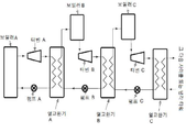
이제, 도 3을 보면, 본 발명의 한 실시예에 따라 작동유로서 물과 암모니아가 사용되는 경우 2단 시스템의 한 예를 예시한 도면이다. Turning now to FIG. 3, which illustrates an example of a two-stage system where water and ammonia are used as the working oil in accordance with one embodiment of the present invention.
한 실시예에서, 간단하게 도시하기 위하여, 오직 하나의 고압 및 저압 터빈이 단 A(1000)에 도시되고, 오직 하나의 단일 단(single stage) 터빈이 단 B(2000)에 도시된다. 뿐만 아니라, 사이클 효율 및 성능을 개선시키기 위한 모든 종래의 기술, 가령, 축열, 개방 급수 히터(open feed water heater) 및 그 밖의 작은 변형예들에 대한 설명은 의도적으로 배제하였다. 효율 개선에 관한 모든 기존의 기술들은 개선된 디자인을 가진 모든 단에 여전히 사용될 수 있다. 이러한 전체 문헌에 언급된 모든 열 및 물리적 특성 값들은 미국 국립 표준 및 테크놀로지(NIST) 웹사이트(www.nist.com) 또는 보다 구체적인 웹사이트(webbook.nist.gov/chemistry/유체)에서 찾아볼 수 있다. In one embodiment, for purposes of simplicity, only one high pressure and low pressure turbine is shown in
한 실시예에서, 여러 단(1000 또는 2000)의 개선된 시스템에서 광범위한 유체가 사용될 수 있지만, 설명을 위해, 본 명세서에서는, 단 A(1000)에서는 제1 작동유로서 물이 사용되고 단 B(2000)에서는 제2 작동유로서 암모니아가 사용된다. 단 A(1000)는 제1단이며, 액체 물이 지점(13)으로부터 펌프 A 1에 의해 고압에서, 가령, 250 bar(또는 임의의 그 밖의 원하는 압력)에서 보일러 A 2로 전달된다. 보일러 2에서, 액체 물은 고온, 가령, 600℃(또는 임의의 그 밖의 원하는 온도)로 가열되며 초임계 또는 가열된 유체로서 지점(10)에서 보일러 A 2로부터 배출된다. 상기 고온 및 고압 초임계 유체는 고압 터빈 3에서 팽창되고 상당한 온도 및 압력 강하 후에, 보일러 A 2로 복귀하여, 50 bar(또는 임의의 그 밖의 원하는 온도 및 압력)에서 600℃로 재가열되고 효율을 생성하도록 최종 에너지 추출을 위해 저압 터빈(4)으로 보내진다. In one embodiment, water is used as the first working fluid in stage A (1000), and stage B (2000) is used as the first working fluid, although for purposes of illustration, a wide variety of fluids may be used in an improved system of several stages (1000 or 2000) Ammonia is used as the second working oil.
기존의 시스템에서, 수증기/증기는 지점(11)에서 거의 진공 상태로 터빈으로부터 배출되고 증발(또는 응축) 시의 잠열은 냉각수를 이용하여 콘덴서에서 폐열로서 제거된다. 이에 따라, 수증기는 지점(12)에서 다시 액체로 변환될 수 있으며 이 액체는 고압으로 본 시스템으로 다시 펌핑되어 사이클을 반복할 수 있다. In existing systems, the steam / steam is discharged from the turbine in a substantially vacuum state at
본 발명에서, 수증기는 지점(11)에서 충분히 높은 압력과 온도로 저압 터빈 A 4로부터 배출되어 잠열 에너지가 제2 작동유로 전달될 수 있으며, 상기 예에서 사용되는 작동유는 암모니아인데, 이 부분이 종래 기술과 다른 주된 부분이다. 이에 따라, 기존의 종래 기술과 비교하였을 때, 단 A(1000)에서의 효율이 약간 감소될 수 있지만, 증발 시의 단 A(1000)의 모든 잠열은 대기(atmosphere)로 폐기되는 대신에 열교환기 A100)에서 단 B(2000)의 작동유로 전달되는데, 이것이 바로 기존의 종래 기술과 상이한 부분이다. 이러한 잠열 에너지를 단 B(2000)로 전달하는 공정에서, 단 A(1000)의 수증기/증기는 지점(12)에서 액체로 다시 변환되며 이 수증기/증기는 응축 펌프 A 1에 의해 고압에서 입력단(13)으로 다시 펌핑될 수 있다. In the present invention, the water vapor can be discharged from the low-
한 실시예에서, 단 B(2000)이 이미 단 A(1000)의 많은 양의 잠열 에너지를 흡수하였기 때문에, 원하는 온도를 구현하기 위해 단 B(2000)에 추가되어야 하는 에너지가 훨씬 적다. 열교환기 A 100)에서 단 A(1000)의 수증기의 잠열 에너지를 흡수함으로써, 암모니아는 지점(14)에서 이미 고온 및 고압 증기로 변환되었다. 상기 예에서, 당업자는, 선택된 압력 및 온도로, 지점(14)에서 암모니아는 증기이라는 사실을 이해할 수 있을 것이다. 하지만, 작동유 B, 이 경우에서는 암모니아는, 단 B를 위해 원하는 작동 압력에 따라, 지점(14)에서 액체, 증기, 또는 초임계 액체 또는 초임계 증기로서, 열교환기 A 100로부터 배출될 수 있다. 그 뒤, 작동유는 보일러 B 5로 유입되는데, 보일러 B 5에서 작동유는 지점(15)에서 터빈 B 6로 유입되기 전에 원하는 온도로 가열된다. 지점(16)에서 저압으로 터빈 B 6로부터 배출될 때, 암모니아는 열교환기 B 100으로 유입되는데, 상기 열교환기에서 암모니아는 지점(17)에서 액체가 될 때까지 냉각된다. 그 뒤, 펌프 B 7이 액체 암모니아를 지점(18)에서 고압(미임계, 임계 또는 초임계 압력일 수 있음)으로 펌핑한다. In one embodiment, since stage B (2000) has already absorbed large amounts of latent heat energy in stage A (1000), there is much less energy to be added to stage B (2000) to achieve the desired temperature. By absorbing the latent heat energy of steam of stage A (1000) in
한 실시예에서, 증발 시의 잠열이 단 A(1000)으로부터 단 B(2000)로 전달될 때, 상당한 양의 전체 에너지 양이 단 B(2000)에 추가되는데, 암모니아를 원하는 온도로 얻기 위해 단 B(2000)에 추가되어야 하는 에너지가 훨씬 적다. 따라서, 제1단 후에, 모든 단들은 매우 높은 효율로 작동될 것이며, 이에 따라 단 A(1000)에서 약간의 효율 감소를 상쇄(compensate)하고도 남을 것이다. In one embodiment, when the latent heat upon evaporation is transferred from
한 실시예에서, 각각의 단은 그 밖의 단들로부터 분리될 수 있으며, 서로 다른 단들에서는 그 어떤 단에서도 유체가 혼합되지 않는다. In one embodiment, each stage can be separate from the other stages, and no fluid is mixed at any stage in the different stages.
한 실시예에서, 각각의 단에서 상이한 유체가 사용될 수 있다. 당업자라면, 그 후의 단들에서 동일한 유체가 사용될 수 있지만, 그보다 낮은 압력에서 사용될 수 있다는 사실을 이해할 것이다. In one embodiment, different fluids may be used at each stage. Those skilled in the art will appreciate that the same fluid may be used in subsequent stages, but may be used at lower pressures.
한 실시예에서, 각각의 단에서, 원할 시에, 그리고, 시스템/발전소의 요건에 따라, 상이한 압력 및 온도가 사용될 수 있다. In one embodiment, different pressures and temperatures may be used at each stage, at will and at the requirements of the system / plant.
한 실시예에서, 본 발명은 기존의 기술 중 임의의 기술, 가령, 축열, 개방 급수 히터, 다단 터빈 등을 사용할 수 있으며, 각각의 개별 단에서도 사용할 수 있다. In one embodiment, the present invention can use any of the existing techniques, such as heat storage, open feed water heater, multi-stage turbine, etc., and can be used in each individual stage.
한 실시예에서, 본 발명은 임의의 열원(heat source)으로 사용될 수 있는데, 이러한 열원은 가령, 석탄, 태양열, 원자력 등을 포함하지만 이들에만 제한되지는 않는다. In one embodiment, the present invention can be used as any heat source including, but not limited to, coal, solar heat, nuclear power, and the like.
한 실시예에서, 임의의 단에서의 증발 시의 잠열은 충분히 높은 온도와 압력에서 그 다음 단의 입력단으로 전달되어 액체로부터 증기 또는 초임계 증기로의 완전한 또는 부분적인 상 변화를 야기하며, 상기 공정에서 제1단의 증기는 액체로 변환될 수 있다. In one embodiment, the latent heat upon evaporation at any stage is transferred to the next stage input at sufficiently high temperature and pressure resulting in complete or partial phase change from liquid to vapor or supercritical steam, The vapor of the first stage can be converted to liquid.
한 실시예에서, 모든 단에서, 하지만, 최종 단에서, 터빈 배출 압력은 대기압 및 대기온 이상일 수 있다. In one embodiment, at all stages, but in the final stage, the turbine discharge pressure may be above atmospheric pressure and atmospheric temperature.
한 실시예에서, 개별 요건들에 따라, 임의의 개수의 단들이 선택되고 작동유가 선택될 수 있다. In one embodiment, in accordance with the individual requirements, any number of stages may be selected and the hydraulic fluid selected.
한 실시예에서, 열로부터 전기로의 변환의 제1단 효율은 현재의 디자인으로 가능한 효율에 비해 약간 작을 수 있다는 사실을 이해해야 한다. 추후 단들은 "가상의(virtual)" 효율을 가질 수 있는데, 이러한 가상의 효율은 밑에서 설명되는 것과 같이 심지어 100%를 초과할 수도 있다. In one embodiment, it should be appreciated that the first stage efficiency of conversion from heat to electric furnace may be slightly less than the efficiency available in the current design. Future stages may have "virtual" efficiency, which may exceed 100%, even as described below.
한 실시예에서, 최고의 결과를 위해(반드시 필요한 것은 아니지만), 단 A(1000)의 작동유는 가장 높은 임계점 온도를 가질 수 있다. 각각의 그 다음 단, 예컨대, 단(2000)은 이전 단보다 더 낮은 임계점 온도를 가진 작동유를 가질 수도 있다. 따라서, 제1단을 위해 선택되는 유체는 일반적으로 물이다. In one embodiment, for best results (although not necessarily), the working fluid of
한 실시예에서, 본 발명은 낮은 단의 가스 연료 발전소(gas fired plant)로서 사용될 수 있다. In one embodiment, the present invention can be used as a low stage gas fired plant.
한 실시예에서, 열교환기(100) 외에도, 한 단으로부터 다음 단으로 열을 전달하기 위해, 열펌프(heat pump)가 사용될 수 있다. 열펌프가 에너지를 소모하고 효율을 감소시킬 수 있기는 하지만, 에너지를 전달하기 위해 몇몇 경우 열교환기에서 유지되어야 할 수도 있는 온도 감소를 없앨 수 있다. 열교환기 내에 온도 감소가 없으면, 보다 우수한 효율을 제공할 수 있으며, 이에 따라 열펌프에 의해 소모되는 에너지를 없애는 데 도움이 될 수 있다. 예를 들어, 온도 차이를 유지하면서도 에너지의 상당량(bulk)을 전달하기 위해서 열교환기가 사용될 수 있으며, 어떠한 온도 차이도 존재하지 못하도록 열펌프를 사용하여 최종 에너지량이 전달될 수 있다. 이는 말기 단(end stage)에서 사용될 수 있다. In one embodiment, in addition to
한 실시예에서, 적어도 2단 시스템을 가진 다단 발전기(multi stage electric power generation apparatus)가 기술된다. 상기 발전기는: 제1 작동유(도시되지 않음)를 포함하며 발전을 위해 구성되며 폐열(증발 및/또는 응축 시의 잠열)을 생성하는 제1단 파워 사이클(1000); 및 제2 작동유(도시되지 않음)를 포함하며 발전을 위해 구성되며 폐열(증발 및/또는 응축 시의 잠열)을 생성하는 제2단 파워 사이클(2000)로 구성되는데, 제2 작동유는 발전을 위해 제1단 파워 사이클로부터 생성된 모든 폐열(증발 및/또는 응축 시의 잠열)을 흡수한다. In one embodiment, a multi-stage electric power generation apparatus having at least two stage systems is described. The generator includes: a first
한 실시예에서, 제1 발전 단(power generating stage)은: 고압에서 제1 작동유를 통과하도록 구성된 제1 수단(1), 고압에서 제1 작동유를 수용하고 제1 작동유를 고온으로 가열시켜 가열된 또는 과열된 유체 또는 증기를 생성시키도록 구성된 제2 수단(2), 가열된 유체/증기를 수용하고 상기 유체/증기를 특정 온도와 압력으로 강하될 때까지 팽창시키도록 구성된 제3 수단(3)과 제4 수단(4), 및 폐열(증발 및/또는 응축 시의 잠열)과 함께 낮은 압력과 온도에서 파워 추출 단(power extraction stage)로부터 배출되는 작동유를 포함한다. In one embodiment, the first power generating stage comprises: a first means (1) configured to pass a first operating fluid at a high pressure, a second means for receiving the first operating fluid at a high pressure, (3) configured to receive the heated fluid / steam and to expand the fluid / steam until it drops to a specific temperature and pressure, a second means (2) configured to generate a superheated fluid or vapor, And fourth means (4), and a working fluid discharged from a power extraction stage at low pressure and temperature together with waste heat (latent heat during evaporation and / or condensation).
한 실시예에서, 본 발명은 열교환기 메커니즘(100)을 포함하되, 열교환기 메커니즘(100)은 제1단(1000)으로부터 생성된 폐열(증발 및/또는 응축 시의 잠열)을 제2단(2000)의 제2 작동유로 전달하여 상기 제2 작동유를 고온 및 고압 유체 또는 증기로 변환시키도록 구성된다. In one embodiment, the present invention includes a
한 실시예에서, 열교환기 메커니즘(100)은, 제1단 파워 사이클(1000) 동안, 제4 수단(4)으로부터 나온 제1 작동유 증기를 수용하여, 상기 제1 작동유 증기가 액체 형태로 변환될 때까지 냉각시켜 제1 수단(1)으로 통과시키도록 구성되거나; 혹은 제2단 파워 사이클(2000) 동안, 제7 수단(7)으로부터 나온 제2 작동유 증기를 수용하여, 단 A(1000)의 폐열 에너지로 상기 제2 작동유 증기를 가열시키도록 구성된다. In one embodiment, the
한 실시예에서, 제2단 파워 사이클은: 고온 및 고압에서 액체 또는 증기 형태로 제2 작동유를 수용하고 상기 액체 또는 증기 형태의 제2 작동유를 고온 및 고압 증기로 가열시키도록 구성된 제5 수단(5); 가열된 증기를 고온 및 고압으로 수용하고, 증기로부터 전기를 생성하며, 증발 및/또는 응축 시의 잠열로 저압 및 저온에서 파워 추출 단으로부터 배출되고 폐열(잠열)이 그 다음 단으로 전달되거나 또는 대기로 배출되는 열교환기(200)에 유입되게 하도록 구성된 제6 수단(6); 및 액체 형태의 제2 작동유를 고압으로 통과시키도록 구성된 제7 수단(7)을 포함한다. In one embodiment, the second stage power cycle comprises: fifth means adapted to receive the second working fluid in liquid or vapor form at high temperature and pressure and to heat the second working fluid in the liquid or vapor form into high temperature and high pressure steam 5); The steam is discharged from the power extraction stage at low pressure and low temperature by evaporation and / or condensation, and the waste heat (latent heat) is transferred to the next stage, A sixth means (6) configured to be introduced into the heat exchanger (200) which is discharged to the heat exchanger (200); And a seventh means (7) configured to pass the second working fluid in liquid form at high pressure.
이제, 도 4를 보면, 본 발명의 한 실시예에 따라 적어도 2단의 잠열 교환 메커니즘을 가진 발전기를 사용하여 전기를 생성하기 위한 방법을 예시한 도면이다. Turning now to FIG. 4, there is illustrated a method for generating electricity using a generator having at least two stages of latent heat exchange mechanisms in accordance with one embodiment of the present invention.
상기 방법이 기술되는 순서는 제한하려는 의도가 아니며 임의의 개수의 기술된 방법 단계들은 임의의 순서대로 조합되어 상기 방법 또는 대안의 방법들을 구현할 수 있다. 또한, 개별 단계들은 본 명세서에 기술된 주제 범위를 벗어나지 않는 한 상기 방법으로부터 생략될 수도 있다. 게다가, 상기 방법은 임의의 적절한 하드웨어, 펌웨어, 또는 이들의 조합으로 구현될 수도 있다. 하지만, 설명을 용이하게 하기 위하여, 밑에서 기술된 실시예들에서, 본 방법은 위에서 기술된 발전기로 구현되는 것을 간주될 수 있다. The order in which the methods are described is not intended to be limiting and any number of the described method steps may be combined in any order to implement the methods or alternative methods. Also, individual steps may be omitted from the methodology, as long as they do not depart from the scope of the subject matter described herein. In addition, the method may be implemented in any suitable hardware, firmware, or combination thereof. However, for ease of explanation, in the embodiments described below, the method may be considered implemented with the generator described above.
단계 402에서, 제1 작동유를 사용하여 전기가 생성된다. 상기 방법은 도 5에 대해 기술할 때 설명된다. In
단계 404에서, 제1 작동유의 증발 및/또는 응축 시의 잠열(폐열)이 제1 유체로부터 물리적으로 분리된 제2 작동유로 전달된다. 이 공정에서, 제1 작동유는 증기로부터 액체 상으로 변환된다. In
단계 406에서, 제1단의 폐열을 모두 흡수하고 난 뒤, 제2 작동유는 추가로 가열되어 전기를 생성하기 위해 원하는 온도를 구현할 수 있다. 전기 생성 방법은 도 6의 기술내용에서 설명된다. In
단계 408에서, 파워 추출 후에, 제2 작동유의 나머지 에너지(폐열)는 폐열로서 주변(surrounding)으로 또는 제3 작동유로 전달될 수 있다. In
이제, 도 5를 보면, 본 발명의 한 실시예에 따라 제1단 파워 사이클(1000) 동안 수행되는 방법을 예시한 도면이다. Turning now to FIG. 5, which illustrates a method performed during a first
단계 502에서, 제1 수단(1)을 사용하여 고압에서 제1 작동유가 통과된다. In
단계 504에서, 제2 수단(2)에 의해 고압에서 제1 작동유가 수용된다. 제2 수단(2)은 제1 작동유를 고온으로 가열시켜 가열된 유체를 생성한다. In
단계 506에서, 가열된 유체는 제3 수단(3)과 제4 수단(4)에 의해 수용된다. 제3 수단(3)과 제4 수단(4)은 가열된 유체가 전기 생성을 위해 특정 온도 및 압력으로 강하될 때까지 팽창된다. In
단계 508에서, 효율을 개선하기 위해 원할 시에 임의의 기존의 수단이 사용될 수 있다. At
단계 510에서, 상기 단에서 생성된 폐열(잠열)은 잠열 교환 메커니즘 A 100에서 제2단 작동유로 전달된다. 상기 공정에서, 제1 작동유는 다시 액체 상으로 변환되고 제1 수단(1)에 제공되며 사이클은 단 A(1000)에서 반복된다. In
이제, 도 6을 보면, 본 발명의 한 실시예에 따라 제2단 파워 사이클(2000) 동안 수행되는 방법을 예시한 도면이다. Turning now to FIG. 6, which illustrates a method performed during a second
단계 602에서, 제7 수단(7)을 사용하여 고압에서 제2 작동유가 통과된다. In
단계 604에서, 단 B(2000)의 제2 작동유는 단 A(1000)의 제1 작동유의 모든 폐열(증발 및/또는 응축 시의 잠열)을 흡수하고 상기 공정에서 온도 및 에너지 함량이 현저하게 올라간다. In
단계 606에서, 제2 작동유는 고온 및 고압에서 열교환기 메커니즘(100)으로부터 배출되는데, 단 A(1000)으로부터 나온 잠열은 제2 작동유에 제공되고, 제5 수단(5)에 의해 고온 및 고압으로 수용되어 원할 시에 최종 온도로 추가로 가열된다. In
단계 608에서, 제2 작동유는 에너지 생성을 위해 고온 및 고압으로 제6 수단(6)에 유입된다. In
단계 610에서, 효율을 개선하기 위해 원할 시에 임의의 기존의 수단이 사용될 수 있다. In
단계 612에서, 제2단(2000)에서 생성된 초과 폐열은 제3 작동유로 전달되거나 혹은 발산되거나 열교환기(200)에 의해 대기로 배출된다. 상기 공정에서, 제2 작동유는 다시 액체 상으로 변환되고 제7 수단(7)에 제공되며 사이클은 단 B(2000)에서 반복된다. In
수증기로부터 액체 물로 상 변화로 배출된 많은 양의 에너지는 오직 또 다른 액체, 상기 예에서는 암모니아에서의 상 변화(완전한 또는 부분적인)로 제거될 수 있다는 사실을 유의해야 한다. 그에 대한 대안은, 강 또는 바다로부터 많은 양의 냉각수를 사용하는 기존의 기술을 이용하는 방법으로서, 이 경우, 잠열은 저온 폐열로서 주변으로 손실된다. 본 발명은 작동유의 모든 잠재 에너지(latent energy)를 상대적으로 저압에서 또 다른 터빈 사이클의 고압 입력단으로 전달할 수 있다. 작동유, 압력 및 온도를 적절하게 선택하면, 원하는 임의의 효율을 구현할 수 있다. It should be noted that the large amount of energy exiting the phase change from water vapor to liquid water can only be removed by phase change (complete or partial) in another liquid, in this example ammonia. An alternative is to use existing techniques that use large amounts of cooling water from the river or sea, in which case latent heat is lost to the environment as cryogenic waste heat. The present invention is able to transfer all latent energy of the operating fluid from the relatively low pressure to the high pressure input of another turbine cycle. By selecting the operating fluid, pressure and temperature appropriately, any desired efficiency can be achieved.
한 실시예에서, 온도 및 압력 또는 사용되는 냉각수를 선택하는 것은 공정을 이해하는 데 도움이 되는 한 예이며, 개별 조건에 따라 임의의 온도 또는 압력 혹은 냉각수가 사용될 수 있다. 중요한 점은, 잠열이 폐열로서 대기로 배출되는 것이 아니라, 냉각수에 따라 터빈 배출 압력 및 온도가 적절하게 선택되어 그 다음 단으로 전달된다는 사실이다. 카르노 공식(Carnot Equation)에 의해 정해진 한계를 초과할 수 있는 이유는, 열로부터 에너지를 추출하기 위해, 상 변화를 이용하는 임의의 시스템에, 이러한 카르노 공식이 실제로는 적용될 수 있기 때문이다. 이 명제를 뒷받침하는 명백한 예는, 작동 중인 어떠한 시스템도 카르노 공식에 의해 정해진 효율에 심지어 조금이라도 근접하지 못한다는 사실이다. 상 변화를 이용하는 임의의 시스템에서, 이상적인 조건 하에서 실제 최대 효율은 다음과 같이 정의된다: In one embodiment, the choice of temperature and pressure or cooling water used is an example to help understand the process, and any temperature or pressure or cooling water may be used depending on the individual conditions. The important point is that latent heat is not discharged to the atmosphere as waste heat, but the turbine exhaust pressure and temperature are appropriately selected and delivered to the next stage depending on the cooling water. The reason for exceeding the limit set by the Carnot Equation is that such a Karno formula can actually be applied to any system that uses phase change to extract energy from the heat. A clear example that supports this proposition is that any system in operation can not even come close to the efficiency set by the Carnot 's formula. In any system utilizing phase change, the actual maximum efficiency under ideal conditions is defined as:
효율 = 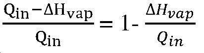
여기서, here,
![]()
![]()
![]()
![]()
상기 공식에서, 터빈으로부터 배출되는 수증기는 포화 증기가 아니다. 포화 증기가 허용되거나 원할 경우에는, 잠열 값은 그에 맞게 조절되어야 한다. 본 명세서의 앞부분에서 기술된 것과 같이 2단이 사용되는 경우에서는, 상기 공식은 다음과 같이: In the above formula, the steam discharged from the turbine is not saturated steam. If saturated steam is acceptable or desired, the latent heat value should be adjusted accordingly. In the case where a two-stage is used as described earlier in this specification, the formula is as follows:
효율 = 
여기서, here,
![]()
![]()
![]()
![]()
![]()
![]()
![]()
![]()
![]()
![]()
이와 비슷하게, 2개보다 많은 단의 경우에서는, 상기 공식은: Similarly, in the case of more than two stages, the formula is:
효율 = 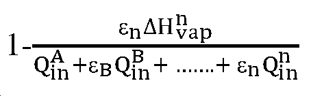
여기서, n은 단의 개수이며, ![]()
![]()
에너지 손실(energy loss)을 감안하면, 상기 공식은: Given energy loss, the formula is:
효율 = 
여기서, ![]()
![]()
상기 공식들로부터, 다음의 결론/사항들을 알 수 있다: From the above formulas, the following conclusions can be drawn:
1) 단의 개수가 크면 클수록, 전체 효율도 점점 더 커질 것이다. The larger the number of stages, the greater the overall efficiency.
2) 이상적인 시스템에서 무제한적인 개수의 단을 사용하면, 효율은 100%에 접근할 것이다. 하지만, 실제로는, 이를 위해 충분한 작동유를 찾는 것은 어려울 것이며 각각의 단이 추가될 때 출력(output)은 감소할 것이며, 이에 따라 출력과 비용을 모두 최적화시키기 위해서는 단의 개수를 3단 또는 4단으로 제한하는 것이 최선일 것이다. 2) Using an unlimited number of stages in an ideal system, the efficiency will approach 100%. In practice, however, it will be difficult to find enough hydraulic fluid to do this, and as each stage is added, the output will decrease, and thus the number of stages can be reduced to three or four stages to optimize both output and cost. It would be best to limit it.
3) 상기 공식들로부터, 증발 시의 낮은 잠열로 작동유를 단순하게 선택하여 시스템의 효율을 올릴 수 있다. 이는 발생하는 경우와 정반대이다. 상기 공식들은 이상적인 조건 즉 에너지, 열, 마찰 또는 그 밖의 손실이 없는 조건에서 발생할 수 있는 것을 보여준다. 실제 조건에서, 낮은 잠열의 유체가 사용되면, 응축 및 공급수 펌프는 생성되는 전체 에너지량 중 큰 부분을 필요로 할 것이다. 화학적 특성 외에도, 물은 매우 큰 증발 잠열로 인해 최고의 선택이 될 것이다. 증발 잠열이 높으면 높을수록, 상 변화 시에 발생되는 팽창 체적(expansion volume)이 더욱더 커질 것이며, 터빈을 효율적으로 구동할 수 있게 함으로써 수증기의 팽창률(expansion ratio)이 매우 커지고, 응축 및 공급수 펌프에 대해 매우 작은 상대적인 파워 조건(power requirement)을 가진다. 3) From the above formulas, it is possible to increase the efficiency of the system by simply selecting the operating fluid with low latent heat during evaporation. This is the opposite of what happens. The formulas show that they can occur under ideal conditions: energy, heat, friction or other loss-free conditions. In practical conditions, if low latent heat fluids are used, condensate and feedwater pumps will require a large proportion of the total energy generated. In addition to its chemical properties, water will be the best choice due to the very large latent heat of evaporation. The higher the latent heat of evaporation, the greater the expansion volume generated during the phase change, and the more efficiently the turbine is driven, the greater the expansion ratio of the steam. And has a very small relative power requirement.
4) 오직, 최종 단의 잠열만이 대기로 배출된다. 4) Only the latent heat of the final stage is released to the atmosphere.
5) 위에 기술된 공식들은 열에너지를 사용가능한 임의의 그 밖의 에너지 형태로 변환하기 위해 상 변화를 이용하는 임의의 시스템에 적용될 것이다. 5) The formulas described above will apply to any system that uses phase change to convert thermal energy to any other available energy form.
6) 현재의 디자인에서, 에너지 추출을 시도하고 최대화하기 위해, 수증기는 일반적으로 포화 증기로서 터빈으로부터 배출되고 저압 터빈 블레이드에 손상을 끼치게 된다. 이러한 디자인에서, 터빈 블레이드 수명을 연장시킬 필요가 없다. 6) In current designs, to try and maximize energy extraction, water vapor is generally discharged from the turbine as saturated steam and damages the low pressure turbine blades. In this design, there is no need to extend the life of the turbine blade.
작동예Operation example : 이론적인 결과: Theoretical results
하기 예는 본 발명에서 설명되는 디자인의 이점을 보여줄 것이다. 그 목적은 개념을 설명하는 데 단지 도움을 주고자 하는 것이며 어떠한 양태로도 본 발명에 따른 디자인의 범위를 본 공정에서 사용되는 특정 유체, 온도 및 압력에 제한하고자 하는 것이 아니다. 지점(10)에서, 초임계 유체가 600℃에서 250 bar 압력에 있는 경우, 3493kJ/Kg의 엔탈피를 가진다. 현재 디자인에서(재가열(reheat)이 없거나 임의의 그 밖의 효율 개선 기술이 없다고 가정하면), 0.1 bar 압력으로 터빈으로부터 배출될 때, 약 2450kJ/Kg의 엔탈피를 가지며, 그 중, 약 2257kJ/Kg은 저급 폐열로서 대기로 제거되는 증발(또는 응축) 시의 잠열로서, 그에 따라 오직 약 35%((3493-2257)/3493)의 효율만이 발생된다. 이제, 이러한 2257kJ/Kg의 폐열이 대기로 배출되지 않으며 매우 효율적인 시스템인지를 확인하는 것이 필요하다. The following example will illustrate the benefits of the design described in the present invention. The purpose is only to aid in explaining the concept, and in no way is it intended to limit the scope of the design according to the invention to the particular fluid, temperature and pressure used in the process. At
한 예로서, 지점(11)에서, 수증기가 터빈으로부터 배출되어 180℃에서 10 bar의 압력으로 콘덴서 A에 유입되는데, 터빈으로부터 배출될 때 엔탈피는 약 2777kJ/Kg일 것이다. 콘덴서 A에서, 이러한 열에너지는 536kJ/Kg의 엔탈피와 40℃의 온도로 지점(18)에서 100 bar로 작동유가 암모니아인 단 B로 전달된다. 사이클 A 및 B에서의 유체는 서로 완전하게 분리되며, 임의의 위치에서 유체들은 직접적으로 접촉되지 않는 것이 필요하다. 이로써, 상이한 단들이 상이한 압력 및 온도에서 작동될 수 있으며, 단의 조건에 따라 조절될 수 있다. 100 bar의 압력에서, 암모니아는 125.17℃ 이상에서 상 변화를 할 것이며 단 A에서 수증기는 10 bar에서 179.88℃ 이하에서 상 변화를 할 것이다. 이러한 온도 차이는 열교환기 A에서 단 A로부터 단 B로의 에너지 전달이 가능하게 할 것이며 암모니아는 액체 상으로부터 증기 상으로 변환되고, 단 A에서 수증기는 액체로 냉각된 뒤 그보다 높은 압력으로 펌핑되어 사이클을 지속하게 된다. 암모니아의 상이 액체로부터 증기로 변화되기 때문에, 수증기로부터 액체 물로의 상 변화에 의해 배열된 많은 양의 에너지가 흡수될 수 있다. 암모니아가 180℃에서 1831kJ/Kg의 엔탈피로 열교환기 A로부터 배출되면, 단 A에서 물 내에 있는 모든 잠재 에너지를 흡수한다. As an example, at
단들 사이에서 전달되어야 하는 에너지의 양과 일치하도록 하기 위하여, 단 B의 흐름 속도는 단 A의 흐름 속도보다 더 높거나 더 낮을 수 있다. 열교환기 A에서, 수증기는 2027kJ/Kg(2777kJ/Kg-750kJ/Kg)를 배출하고, 암모니아는 오직 1295kJ/Kg(1831kJ/Kg-536kJ/Kg)만을 흡수할 수 있다. 상기 특정 예에서, 이 모든 에너지를 전달하기 위하여, 암모니아의 질량 흐름 속도는 액체로 변환하는데 필요한 에너지를 모두 흡수하기 위해 물의 질량 흐름 속도보다 1.56배(2027kJ/Kg/1295kJ/Kg) 만큼 더 커야 한다. 암모니아 사이클에 대해 이보다 더 낮거나 더 높은 흐름 속도 비율이 바람직한 경우, 조건들에 따라 단 A의 온도와 터빈 배출 압력을 단순히 증가시키거나 감소시키기만 하면 된다. The flow rate of stage B may be higher or lower than the flow rate of stage A so as to match the amount of energy that must be transferred between stages. In heat exchanger A, the water vapor exits 2027 kJ / Kg (2777 kJ / Kg-750 kJ / Kg) and ammonia can absorb only 1295 kJ / Kg (1831 kJ / Kg-536 kJ / Kg). In this particular example, to deliver all of this energy, the mass flow rate of ammonia must be greater by 1.56 times (2027 kJ / Kg / 1295 kJ / Kg) than the mass flow rate of water to absorb all of the energy required to convert it to liquid . If lower or higher flow rate ratios are desired for the ammonia cycle, simply increase or decrease the temperature of the stage A and the turbine discharge pressure according to the conditions.
열교환기 내에 약 50℃의 온도 차이가 유지되어 에너지가 한 단으로부터 그 다음 단으로 전달될 수 있으며, 원할 시에 또는 필요 시에는 최종적인 양의 에너지 전달을 위해 열펌프가 사용될 수 있다. 이보다 더 적거나 큰 온도 차이가 바람직한 경우에는, 그에 따라 계산이 조절될 것이다. 또한, 한 단으로부터 그 다음 단으로 열을 전달하기 위해 열펌프가 사용될 수 있는데, 이 경우, 온도 차이는 0이거나 특정 경우에 필요 시에는 심지어 음의 값이 될 수도 있다. 이에 따라, 각각의 단에서는 약간 높은 효율이 발생할 수 있지만, 이것이 바람직한지를 결정하기 위하여 열펌프에 의해 사용되는 에너지도 고려해야 한다. A temperature difference of about 50 ° C is maintained in the heat exchanger so that energy can be transferred from one stage to the next, and a heat pump can be used to deliver the final positive energy when desired or as needed. If less or greater temperature differences are desired, the calculations will be adjusted accordingly. Also, a heat pump can be used to transfer heat from one stage to the next, in which case the temperature difference may be zero or even negative if necessary in certain cases. Thus, although slightly higher efficiencies may occur at each stage, the energy used by the heat pump should also be considered to determine if this is desirable.
도 3에 도시된 시스템은 단 A의 효율을 약간 감소되게 할 수 있지만, 단 A의 잠열을 단 B의 입력으로 전달하고 작동유를 지점(14)에서 고압 증기로 만들면, 도 3에 도시된 것과 같이 암모니아 온도를 180℃로부터 420℃로 올리고 약 781kJ/Kg(2612kJ/Kg-1831kJ/Kg=781kJ/Kg)를 위해, 보일러 B에서 약간의 여분의 에너지만이 필요하게 된다. 이를 비교해 보면, 단 A에 3484kJ/Kg가 추가된다. 이는 단 B에 대한 "가상"의 효율로서 ((2612-1637)/(2612-1831))*100 = 125%가 된다. 첫 번째의 2단에 대한 평균 효율은 (전체 에너지 출력)/(전체 에너지 입력)=((3493-2926)+(3667-2777)+1.56*(2612-1637))/(3493-750+3667-2926+1.56*(2612-1831)) = 63.3%가 된다. 이 숫자는 물론 어떠한 에너지 손실도 고려하지 않았기 때문에 근사값이다. 하지만, 단지 2개의 단순 단을 사용하면(단 A에서 오직 하나의 재가열(reheat)을 사용하면), 디자인은 현재의 디자인 시스템으로 가능한 모든 성능 한계(performance limit)를 이미 현저하게 초과하게 된다. 제3단은 카르노 공식에 의해 설정된 효율을 초과하는 효율을 가지게 되어 이를 무효화시킬 것이다. 무제한적인 개수의 단과 이상적인 시스템을 사용하면, 실제로 거의 100%의 효율에 접근할 수 있다. The system shown in FIG. 3 can cause the efficiency of stage A to be slightly reduced, but if the latent heat of A is delivered to input B and the hydraulic fluid is at high pressure steam at
위에서 논의된 대표 실시예들은 특정 이점을 제공할 수 있다. 본 명세서의 양태들을 실시하는 데 반드시 필요하지는 않지만, 이러한 이점들은 다음 내용들을 포함할 수 있다: The exemplary embodiments discussed above may provide specific advantages. Although not necessarily required to practice the aspects of the present specification, these advantages may include the following:
- 파워 단위 당 비용이 감소할 것이다. 동일한 양의 전기 출력을 위해, 더 적은 연료가 연소되기 때문에 오염이 줄어들 것이다. - Cost per unit of power will decrease. For the same amount of electrical output, less fuel will burn and contamination will decrease.
- 오염 때문에, 지구 온도가 현저하게 증가되는 위험에 처해 있는데, 이를 현저하게 제거할 수 있다. - Due to contamination, the Earth is at risk of a significant increase in temperature, which can be significantly eliminated.
- 또 다른 이점에 따르면, 상대적으로 작은 추가 투자만으로도, 기존의 전기 생성 성능이 현저하게 증가될 것이다. - According to another advantage, the relatively small additional investment alone will significantly increase the existing electricity generating capacity.
당업자라면, 본 발명에서 다양한 수단들이 사용된다는 것을 이해할 수 있을 것이다. 각각의 수단은 위에서 논의된 특정 기능들을 수행하기 위한 특정 장치이다. 예를 들어, Those skilled in the art will appreciate that various means are used in the present invention. Each means is a specific device for performing the specific functions discussed above. E.g,
- 제1 수단 및 제7 수단은 펌프 및 펌프의 기능과 유사한 기능을 가진 장치들을 포함할 수 있지만 이들에만 제한되지는 않는다. The first and seventh means may include but are not limited to devices having a function similar to that of the pump and pump.
- 제2 수단 및 제5 수단은 보일러 및 보일러의 기능과 유사한 기능을 가진 장치들을 포함할 수 있지만 이들에만 제한되지는 않는다. The second and fifth means may include but are not limited to devices having a function similar to that of the boiler and the boiler.
- 제3 수단, 제4 수단, 및 제6 수단은 고압 터빈과 저압 터빈, 및 고압/저압 터빈의 기능과 유사한 기능을 가진 장치들을 포함할 수 있지만 이들에만 제한되지는 않는다. The third means, the fourth means, and the sixth means may include, but are not limited to, a high pressure turbine and a low pressure turbine, and devices having functions similar to those of the high pressure / low pressure turbine.
본 발명에서 증발 시의 잠열을 리사이클링하여 고효율 에너지 변환 사이클을 위한 시스템을 구현하는 방법이 특정의 구성 특징 및/또는 방법들로 기술되었지만, 청구항들은 앞에 기술된 특징 또는 방법들에만 제한될 필요가 없다는 사실을 이해해야 한다. 상기 특정의 특징 및 방법들은 증발 시의 잠열을 리사이클링하여 고효율 에너지 변환 사이클을 위한 시스템을 구현하기 위한 한 예로서 기술된다. Although the present invention describes a method for recycling a latent heat upon evaporation to implement a system for a high-efficiency energy conversion cycle with certain constituent features and / or methods, it should be understood that the claims are not limited to the features or methods described above You must understand the facts. These specific features and methods are described as an example for recycling the latent heat upon evaporation to implement a system for a high efficiency energy conversion cycle.
본 명세서에서 언급된 예들은 본 발명에 따른 디자인의 범위를 제한하려는 것이 아니라 오직 디자인의 기본 개념을 이해하는데 도움을 주고자 하는 것이다. 중요한 사실은, 현재 실시되고 있는 것과 같이 대기로 배출되는 대신, 증발/응축 시의 잠열(폐열)이 그 다음 단들로 전달되어 전기 변환에 열의 효율을 증가시킨다는 점이다. 또한, 본 명세서에서 기술되는 것과 같이, 증발/응축 시의 잠열(폐열)을 이용하여, 약간의 변형 또는 대안예를 가진 모든 디자인들도 본 발명의 범위 내에서 다루어진다. The examples referred to in this specification are not intended to limit the scope of the design according to the invention, but merely to aid in understanding the basic concepts of the design. Importantly, instead of being discharged to the atmosphere as is currently practiced, latent heat (waste heat) during evaporation / condensation is transferred to the next stages, thereby increasing the efficiency of heat conversion. Also, as described herein, all designs with slight modifications or alternatives, using latent heat (waste heat) during evaporation / condensation, are also contemplated within the scope of the present invention.
Claims (18)
- 제1 작동유를 포함하며 전기를 생성하여 증발 및/또는 응축 시의 잠열(폐열) 에너지를 포함하는 터빈 배출 증기를 생성하도록 구성된 제1단 파워 사이클; 및
- 제2 작동유를 포함하며 전기를 생성하도록 구성된 제2단 파워 사이클을 포함하되,
상기 제2 작동유는 전기 생성을 위해 제1단 파워 사이클로부터 생성된 증발 및/또는 응축 시의 잠열(폐열)을 흡수하는 것을 특징으로 하는 적어도 2단의 잠열(폐열) 교환 메커니즘을 가진 다단 발전기. A multistage power generator having at least two stages of latent heat (waste heat) exchange mechanism, said generator comprising:
A first stage power cycle comprising a first hydraulic fluid and configured to generate electricity to generate turbine discharge steam comprising latent heat (waste heat) energy during evaporation and / or condensation; And
- a second stage power cycle comprising a second hydraulic fluid and configured to generate electricity,
Wherein the second hydraulic oil absorbs latent heat (waste heat) during evaporation and / or condensation generated from the first stage power cycle for electricity generation.
- 고압에서 제1 작동유를 통과하도록 구성된 제1 수단을 포함하고;
- 제2 수단을 포함하되, 상기 제2 수단은 고압에서 제1 작동유를 수용하고 제1 작동유를 고온으로 가열시켜 가열된 유체/증기를 생성하도록 구성되며,
- 제3 및 제4 수단을 포함하되, 상기 제3 및 제4 수단은, 가열된 유체/증기를 수용하고, 상기 가열된 유체/증기를 특정 온도 및 압력으로 강하될 때까지 팽창시켜, 강하된 온도 및 압력으로 상기 가열된 유체를 폐열 교환 메커니즘으로 통과시키도록 구성되는 것을 특징으로 하는 적어도 2단의 잠열(폐열) 교환 메커니즘을 가진 다단 발전기. 2. The method of claim 1, wherein the first stage power cycle comprises:
- first means configured to pass through the first operating fluid at high pressure;
The second means being adapted to receive the first working fluid at a high pressure and to heat the first working fluid to a high temperature to produce a heated fluid /
The third and fourth means comprise means for receiving the heated fluid / steam and expanding the heated fluid / steam until it drops to a specific temperature and pressure, (Heat exchange) mechanism for passing the heated fluid through the waste heat exchange mechanism at a predetermined temperature and pressure.
- 제5 수단을 포함하되, 상기 제5 수단은 고온 및 고압에서 액체 또는 증기 형태의 제2 작동유를 수용하고 증기 형태의 제2 작동유를 바람직한 작동 온도로 가열시키도록 구성되며;
- 가열된 증기를 고온 및 고압에서 수용하고 증기로부터 전기를 생성하도록 구성된 제6 수단을 포함하되, 증기는 저온 및 저압에서 발전기로부터 배출되며 또 다른 열교환기에 유입되어 폐열을 제3단 파워 사이클로 전달하거나 대기로 배출하고;
- 제2 작동유를 고압으로 통과시키도록 구성된 제7 수단을 포함하는 것을 특징으로 하는 적어도 2단의 잠열(폐열) 교환 메커니즘을 가진 다단 발전기. 2. The method of claim 1 wherein the second stage power cycle comprises:
- fifth means, said fifth means being adapted to receive a second working fluid in the form of a liquid or vapor at a high temperature and a high pressure and to heat the second working fluid in the vapor form to a desired operating temperature;
And a sixth means configured to receive the heated steam at a high temperature and a high pressure and to generate electricity from the steam, wherein the steam is discharged from the generator at low and low pressures and flows into another heat exchanger to transfer the waste heat to a third stage power cycle To the atmosphere;
- a seventh means configured to pass the second hydraulic fluid at high pressure. ≪ Desc / Clms Page number 20 >
- 제1단 파워 사이클 동안, 제4 수단으로부터 제1 작동유 증기를 수용하고 상기 제1 작동유 증기가 액체 형태로 변환될 때까지 냉각시켜 제1 수단으로 통과시키거나; 혹은
- 제2단 파워 사이클 동안, 제6 수단으로부터 제2 작동유 증기를 수용하고 상기 제2 작동유 증기가 액체 형태로 변환될 때까지 냉각시켜 제7 수단으로 통과시키도록 구성되는 것을 특징으로 하는 적어도 2단의 잠열(폐열) 교환 메커니즘을 가진 다단 발전기. 6. The heat exchanger mechanism according to any one of claims 1 to 5, further comprising:
- during the first stage power cycle, receiving the first hydraulic fluid from the fourth means and cooling the first hydraulic fluid until the first hydraulic fluid is converted to a liquid form and passing it to the first means; or
Characterized in that during the second stage power cycle it is configured to receive the second working fluid from the sixth means and to cool it to the seventh means until the second working fluid vapor is converted into a liquid form, A multistage generator with a latent heat exchange mechanism.
- 제1 작동유를 포함하는 제1단 파워 사이클에서, 전력, 및 폐열(증발 및/또는 응축 시의 잠열)을 함유하는 터빈 배출 증기를 생성하는 단계; 및
- 제2 작동유를 포함하는 제2단 파워 사이클에서, 전력, 및 폐열(증발 및/또는 응축 시의 잠열)을 생성하는 단계를 포함하되,
제2 작동유는 전기를 생성하기 위한 열교환 메커니즘에서 제1단으로부터 생성된 폐열(증발 및/또는 응축 시의 잠열)을 흡수하는 것을 특징으로 하는 적어도 2단 파워 사이클을 가진 발전기를 사용하여 전기를 생성하기 위한 방법. A method for generating electricity using a generator having at least a two-stage power cycle, the method comprising:
- generating a turbine exhaust steam containing power and waste heat (latent heat during evaporation and / or condensation) in a first stage power cycle comprising a first operating fluid; And
- generating power and waste heat (latent heat in evaporation and / or condensation) in a second stage power cycle comprising a second operating fluid,
Wherein the second hydraulic oil absorbs waste heat (latent heat in evaporation and / or condensation) generated from the first stage in a heat exchange mechanism for generating electricity, and generates electricity using a generator having at least two stages power cycle Lt; / RTI >
- 제1 수단에 의해, 고압에서 제1 작동유를 통과시키는 단계;
- 제2 수단에 의해, 고압에서 제1 작동유를 수용하는 단계;
- 제2 수단에 의해, 제1 작동유를 고온으로 가열시키는 단계;
- 제3 수단에 의해, 가열된 유체를 수용하며, 상기 유체를 특정 온도와 압력으로 강하될 때까지 팽창시키고, 강하된 온도와 압력으로 유체를 재가열시키기 위해 강하된 온도와 압력으로 상기 가열된 유체를 제2 수단으로 통과시키는 단계를 포함하되, 가열된 유체는 강하된 온도와 압력으로 재가열되며;
- 제4 수단에 의해, 고온 및 저압 또는 중압(intermediate pressure)에서 생성된 증기로부터 전기를 생성하는 단계;
- 제4 수단에 의해, 증발 및/또는 응축 시의 잠열 에너지를 함유하는, 저온 및 저압 배출 증기를 생성하는 단계를 포함하는 것을 특징으로 하는 적어도 2단 파워 사이클을 가진 발전기를 사용하여 전기를 생성하기 위한 방법. 15. The method of claim 14,
Passing the first hydraulic fluid at high pressure by first means;
- receiving a first hydraulic fluid at a high pressure, by a second means;
- heating the first operating fluid to a high temperature by a second means;
A third means for receiving the heated fluid, expanding the fluid until it drops to a specific temperature and pressure, and delivering the heated fluid at a lowered temperature and pressure to reheat the fluid at the lowered temperature and pressure, To a second means, wherein the heated fluid is reheated to a lowered temperature and pressure;
- generating electricity from the steam produced at high temperature and low pressure or intermediate pressure by means of fourth means;
Generating a low temperature and low pressure discharge steam containing latent heat energy at the time of evaporation and / or condensation by means of a fourth means; generating electricity using a generator having at least two stages of power cycles; Lt; / RTI >
- 제5 수단을 사용하여, 고온 및 고압에서, 열교환기 메커니즘으로부터, 증기 형태 또는 상 변화되는 가열된 유체에서 제2 작동유를 수용하는 단계;
- 제5 수단을 사용하여, 증기 형태에서 제2 작동유를 필요 온도로 가열하는 단계;
- 제6 수단을 사용하여, 고온 및 고압에서 가열된 증기를 수용하고, 생성된 증기로부터 전기를 생성하며, 증발 및/또는 응축 시의 잠열을 함유하는 저온 및 저압에서 제6 수단으로부터 배출시키는 단계; 및
- 제7 수단을 사용하여, 고압에서 제2 작동유를 통과시키는 단계를 포함하는 것을 특징으로 하는 적어도 2단 파워 사이클을 가진 발전기를 사용하여 전기를 생성하기 위한 방법. 15. The method of claim 14,
- receiving the second hydraulic fluid from the heat exchanger mechanism, at a high temperature and a high pressure, in vapor form or in a phase-changing heated fluid, using the fifth means;
- heating the second working fluid in vapor form to a required temperature, using the fifth means;
- using the sixth means to receive steam heated at high and high pressures, generate electricity from the resulting steam, and vent from the sixth means at low and low pressures containing latent heat during evaporation and / or condensation ; And
- passing the second hydraulic fluid at high pressure using the seventh means. ≪ RTI ID = 0.0 > - < / RTI >
- 열교환기 메커니즘을 사용하여, 제1단 파워 사이클 동안, 제4 수단으로부터 제1 작동유 증기를 수용하고 액체 형태로 변환될 때까지 냉각시켜 제1 수단으로 통과시키는 단계; 또는
- 열교환기 메커니즘을 사용하여, 제2단 파워 사이클 동안, 제6 수단으로부터 제2 작동유 증기를 수용하고 액체 형태로 변환될 때까지 냉각시켜 제7 수단으로 통과시키는 단계; 및
- 열교환기 메커니즘을 사용하여, 제2단 파워 사이클 후에 증발 시의 잠열을 그 다음 단으로 배출하거나 전달하는 단계를 포함하는 것을 특징으로 하는 적어도 2단 파워 사이클을 가진 발전기를 사용하여 전기를 생성하기 위한 방법. 15. The method of claim 14,
- using a heat exchanger mechanism to cool the first hydraulic fluid from the fourth means during the first stage power cycle until it is converted to a liquid form and pass it to the first means; or
- using a heat exchanger mechanism, during the second stage power cycle, cooling the second hydraulic fluid from the sixth means until it is converted to a liquid form and passing it to the seventh means; And
- discharging or transferring the latent heat during evaporation to the next stage after the second stage power cycle using a heat exchanger mechanism to generate electricity using at least two stage power cycle Way.
Applications Claiming Priority (3)
| Application Number | Priority Date | Filing Date | Title |
|---|---|---|---|
| IN3127DE2014 | 2014-10-31 | ||
| IN3127/DEL/2014 | 2014-10-31 | ||
| PCT/IB2015/058331 WO2016067225A2 (en) | 2014-10-31 | 2015-10-29 | A system for high efficiency energy conversion cycle by recycling latent heat of vaporization |
Related Child Applications (1)
| Application Number | Title | Priority Date | Filing Date |
|---|---|---|---|
| KR1020207031645A Division KR20200128594A (en) | 2014-10-31 | 2015-10-29 | A system for high efficiency energy conversion cycle by recycling latent heat of vaporization |
Publications (1)
| Publication Number | Publication Date |
|---|---|
| KR20170077159A true KR20170077159A (en) | 2017-07-05 |
Family
ID=55858474
Family Applications (2)
| Application Number | Title | Priority Date | Filing Date |
|---|---|---|---|
| KR1020177013549A Ceased KR20170077159A (en) | 2014-10-31 | 2015-10-29 | A system for high efficiency energy conversion cycle by recycling latent heat of vaporization |
| KR1020207031645A Ceased KR20200128594A (en) | 2014-10-31 | 2015-10-29 | A system for high efficiency energy conversion cycle by recycling latent heat of vaporization |
Family Applications After (1)
| Application Number | Title | Priority Date | Filing Date |
|---|---|---|---|
| KR1020207031645A Ceased KR20200128594A (en) | 2014-10-31 | 2015-10-29 | A system for high efficiency energy conversion cycle by recycling latent heat of vaporization |
Country Status (12)
| Country | Link |
|---|---|
| US (1) | US20170248040A1 (en) |
| EP (1) | EP3227533A4 (en) |
| JP (1) | JP2017533380A (en) |
| KR (2) | KR20170077159A (en) |
| CN (1) | CN107002511A (en) |
| AU (1) | AU2015413548B2 (en) |
| BR (1) | BR112017008206B1 (en) |
| CA (1) | CA2964325C (en) |
| EA (1) | EA038785B1 (en) |
| MX (1) | MX2017005131A (en) |
| MY (1) | MY189450A (en) |
| WO (1) | WO2016067225A2 (en) |
Families Citing this family (2)
| Publication number | Priority date | Publication date | Assignee | Title |
|---|---|---|---|---|
| GB2535181A (en) * | 2015-02-11 | 2016-08-17 | Futurebay Ltd | Apparatus and method for energy storage |
| GB2552963A (en) * | 2016-08-15 | 2018-02-21 | Futurebay Ltd | Thermodynamic cycle apparatus and method |
Family Cites Families (16)
| Publication number | Priority date | Publication date | Assignee | Title |
|---|---|---|---|---|
| JPS4949333U (en) * | 1972-08-09 | 1974-04-30 | ||
| JPS61152915A (en) * | 1984-12-26 | 1986-07-11 | Kawasaki Heavy Ind Ltd | Energy recovering system |
| US5440882A (en) * | 1993-11-03 | 1995-08-15 | Exergy, Inc. | Method and apparatus for converting heat from geothermal liquid and geothermal steam to electric power |
| US5822990A (en) * | 1996-02-09 | 1998-10-20 | Exergy, Inc. | Converting heat into useful energy using separate closed loops |
| DE19907512A1 (en) * | 1999-02-22 | 2000-08-31 | Frank Eckert | Apparatus for Organic Rankine Cycle (ORC) process has a fluid regenerator in each stage to achieve a greater temperature differential between the cascade inlet and outlet |
| JP2002285907A (en) * | 2001-03-27 | 2002-10-03 | Sanyo Electric Co Ltd | Recovery refrigeration system of exhaust heat for micro gas turbine |
| US6948315B2 (en) * | 2004-02-09 | 2005-09-27 | Timothy Michael Kirby | Method and apparatus for a waste heat recycling thermal power plant |
| JP2008202474A (en) * | 2007-02-19 | 2008-09-04 | Toyota Motor Corp | Waste heat recovery device and engine |
| US20100263380A1 (en) * | 2007-10-04 | 2010-10-21 | United Technologies Corporation | Cascaded organic rankine cycle (orc) system using waste heat from a reciprocating engine |
| US8522552B2 (en) * | 2009-02-20 | 2013-09-03 | American Thermal Power, Llc | Thermodynamic power generation system |
| CN101614139A (en) * | 2009-07-31 | 2009-12-30 | 王世英 | Multicycle power generation thermodynamic system |
| US9046006B2 (en) * | 2010-06-21 | 2015-06-02 | Paccar Inc | Dual cycle rankine waste heat recovery cycle |
| US20130160449A1 (en) * | 2011-12-22 | 2013-06-27 | Frederick J. Cogswell | Cascaded organic rankine cycle system |
| US9018778B2 (en) * | 2012-01-04 | 2015-04-28 | General Electric Company | Waste heat recovery system generator varnishing |
| JP6013140B2 (en) * | 2012-11-01 | 2016-10-25 | 株式会社東芝 | Power generation system |
| JP2014199047A (en) * | 2013-03-15 | 2014-10-23 | 株式会社東芝 | Geothermal power generation system |
-
2015
- 2015-10-29 CN CN201580055257.XA patent/CN107002511A/en active Pending
- 2015-10-29 AU AU2015413548A patent/AU2015413548B2/en not_active Ceased
- 2015-10-29 KR KR1020177013549A patent/KR20170077159A/en not_active Ceased
- 2015-10-29 BR BR112017008206-3A patent/BR112017008206B1/en not_active IP Right Cessation
- 2015-10-29 WO PCT/IB2015/058331 patent/WO2016067225A2/en not_active Ceased
- 2015-10-29 CA CA2964325A patent/CA2964325C/en active Active
- 2015-10-29 US US15/517,285 patent/US20170248040A1/en not_active Abandoned
- 2015-10-29 KR KR1020207031645A patent/KR20200128594A/en not_active Ceased
- 2015-10-29 EA EA201790859A patent/EA038785B1/en unknown
- 2015-10-29 EP EP15890168.6A patent/EP3227533A4/en not_active Withdrawn
- 2015-10-29 MY MYPI2017701248A patent/MY189450A/en unknown
- 2015-10-29 JP JP2017519926A patent/JP2017533380A/en active Pending
- 2015-10-29 MX MX2017005131A patent/MX2017005131A/en unknown
Also Published As
| Publication number | Publication date |
|---|---|
| CA2964325C (en) | 2020-10-27 |
| BR112017008206A2 (en) | 2017-12-26 |
| WO2016067225A2 (en) | 2016-05-06 |
| US20170248040A1 (en) | 2017-08-31 |
| CN107002511A (en) | 2017-08-01 |
| WO2016067225A3 (en) | 2016-06-23 |
| AU2015413548A1 (en) | 2017-08-03 |
| MX2017005131A (en) | 2019-02-20 |
| EP3227533A4 (en) | 2018-07-11 |
| EP3227533A1 (en) | 2017-10-11 |
| KR20200128594A (en) | 2020-11-13 |
| BR112017008206B1 (en) | 2023-10-31 |
| JP2017533380A (en) | 2017-11-09 |
| MY189450A (en) | 2022-02-14 |
| AU2015413548B2 (en) | 2019-08-15 |
| EA201790859A1 (en) | 2017-11-30 |
| CA2964325A1 (en) | 2016-05-06 |
| EA038785B1 (en) | 2021-10-19 |
Similar Documents
| Publication | Publication Date | Title |
|---|---|---|
| EP2021587B1 (en) | A method and system for generating power from a heat source | |
| EP2834477B1 (en) | System and method for recovery of waste heat from dual heat sources | |
| US20100269503A1 (en) | Method and device for converting thermal energy of a low temperature heat source to mechanical energy | |
| JPS63277808A (en) | Thermodynamic cycle method using mixture as working fluid | |
| US20150075210A1 (en) | Method for charging and discharging a heat accumulator and plant for storing and releasing thermal energy, suitable for this method | |
| CN108603418B (en) | Heat recovery system and method of converting heat into electrical energy using heat recovery system | |
| CN104895630A (en) | Different evaporation temperature based multistage organic Rankine cycle (ORC) power generation system | |
| KR20170077159A (en) | A system for high efficiency energy conversion cycle by recycling latent heat of vaporization | |
| RU2560503C1 (en) | Heat power plant operation mode | |
| RU2560505C1 (en) | Heat power plant operation mode | |
| RU2646853C1 (en) | Nuclear turbo-air installation with return of cycle air part from compressor to the last stages of turbine | |
| Patel et al. | A review: Utilization of waste energy to improve the efficiency of the systems | |
| RU2555600C1 (en) | Operating method of thermal power plant | |
| RU2555597C1 (en) | Operating method of thermal power plant | |
| WO2015075537A2 (en) | Cascaded power plant using low and medium temperature source fluid | |
| KR20140079744A (en) | Power generation system that combines a heat pump and heat engine | |
| RU2562727C1 (en) | Utilisation method of thermal energy generated by thermal power station | |
| RU2560510C1 (en) | Operating method of thermal power plant | |
| RU2562728C1 (en) | Utilisation method of thermal energy generated by thermal power plant | |
| RU2562741C1 (en) | Utilisation method of thermal energy generated by thermal power plant | |
| RU2560611C1 (en) | Heat power plant operation mode | |
| EP3075969A1 (en) | Energy storage system and method |
Legal Events
| Date | Code | Title | Description |
|---|---|---|---|
| PA0105 | International application |
Patent event date: 20170519 Patent event code: PA01051R01D Comment text: International Patent Application |
|
| PG1501 | Laying open of application | ||
| A201 | Request for examination | ||
| PA0201 | Request for examination |
Patent event code: PA02012R01D Patent event date: 20180723 Comment text: Request for Examination of Application |
|
| E902 | Notification of reason for refusal | ||
| PE0902 | Notice of grounds for rejection |
Comment text: Notification of reason for refusal Patent event date: 20190613 Patent event code: PE09021S01D |
|
| AMND | Amendment | ||
| E601 | Decision to refuse application | ||
| PE0601 | Decision on rejection of patent |
Patent event date: 20200401 Comment text: Decision to Refuse Application Patent event code: PE06012S01D Patent event date: 20190613 Comment text: Notification of reason for refusal Patent event code: PE06011S01I |
|
| X091 | Application refused [patent] | ||
| AMND | Amendment | ||
| PX0901 | Re-examination |
Patent event code: PX09011S01I Patent event date: 20200401 Comment text: Decision to Refuse Application Patent event code: PX09012R01I Patent event date: 20191213 Comment text: Amendment to Specification, etc. |
|
| PX0601 | Decision of rejection after re-examination |
Comment text: Decision to Refuse Application Patent event code: PX06014S01D Patent event date: 20200731 Comment text: Amendment to Specification, etc. Patent event code: PX06012R01I Patent event date: 20200630 Comment text: Decision to Refuse Application Patent event code: PX06011S01I Patent event date: 20200401 Comment text: Amendment to Specification, etc. Patent event code: PX06012R01I Patent event date: 20191213 Comment text: Notification of reason for refusal Patent event code: PX06013S01I Patent event date: 20190613 |
|
| X601 | Decision of rejection after re-examination | ||
| A107 | Divisional application of patent | ||
| PA0104 | Divisional application for international application |
Comment text: Divisional Application for International Patent Patent event code: PA01041R01D Patent event date: 20201102 |