KR20170077177A - Ion implanter comprising integrated ventilation system - Google Patents
Ion implanter comprising integrated ventilation system Download PDFInfo
- Publication number
- KR20170077177A KR20170077177A KR1020177014199A KR20177014199A KR20170077177A KR 20170077177 A KR20170077177 A KR 20170077177A KR 1020177014199 A KR1020177014199 A KR 1020177014199A KR 20177014199 A KR20177014199 A KR 20177014199A KR 20170077177 A KR20170077177 A KR 20170077177A
- Authority
- KR
- South Korea
- Prior art keywords
- gas
- box
- monitoring
- flow
- exhaust
- Prior art date
- Legal status (The legal status is an assumption and is not a legal conclusion. Google has not performed a legal analysis and makes no representation as to the accuracy of the status listed.)
- Granted
Links
Images

Classifications
-
- H01L21/67017—
-
- H—ELECTRICITY
- H10—SEMICONDUCTOR DEVICES; ELECTRIC SOLID-STATE DEVICES NOT OTHERWISE PROVIDED FOR
- H10P—GENERIC PROCESSES OR APPARATUS FOR THE MANUFACTURE OR TREATMENT OF DEVICES COVERED BY CLASS H10
- H10P72/00—Handling or holding of wafers, substrates or devices during manufacture or treatment thereof
- H10P72/04—Apparatus for manufacture or treatment
- H10P72/0402—Apparatus for fluid treatment
-
- C—CHEMISTRY; METALLURGY
- C23—COATING METALLIC MATERIAL; COATING MATERIAL WITH METALLIC MATERIAL; CHEMICAL SURFACE TREATMENT; DIFFUSION TREATMENT OF METALLIC MATERIAL; COATING BY VACUUM EVAPORATION, BY SPUTTERING, BY ION IMPLANTATION OR BY CHEMICAL VAPOUR DEPOSITION, IN GENERAL; INHIBITING CORROSION OF METALLIC MATERIAL OR INCRUSTATION IN GENERAL
- C23C—COATING METALLIC MATERIAL; COATING MATERIAL WITH METALLIC MATERIAL; SURFACE TREATMENT OF METALLIC MATERIAL BY DIFFUSION INTO THE SURFACE, BY CHEMICAL CONVERSION OR SUBSTITUTION; COATING BY VACUUM EVAPORATION, BY SPUTTERING, BY ION IMPLANTATION OR BY CHEMICAL VAPOUR DEPOSITION, IN GENERAL
- C23C14/00—Coating by vacuum evaporation, by sputtering or by ion implantation of the coating forming material
- C23C14/22—Coating by vacuum evaporation, by sputtering or by ion implantation of the coating forming material characterised by the process of coating
- C23C14/48—Ion implantation
-
- H—ELECTRICITY
- H01—ELECTRIC ELEMENTS
- H01J—ELECTRIC DISCHARGE TUBES OR DISCHARGE LAMPS
- H01J37/00—Discharge tubes with provision for introducing objects or material to be exposed to the discharge, e.g. for the purpose of examination or processing thereof
- H01J37/30—Electron-beam or ion-beam tubes for localised treatment of objects
- H01J37/317—Electron-beam or ion-beam tubes for localised treatment of objects for changing properties of the objects or for applying thin layers thereon, e.g. for ion implantation
- H01J37/3171—Electron-beam or ion-beam tubes for localised treatment of objects for changing properties of the objects or for applying thin layers thereon, e.g. for ion implantation for ion implantation
-
- H—ELECTRICITY
- H10—SEMICONDUCTOR DEVICES; ELECTRIC SOLID-STATE DEVICES NOT OTHERWISE PROVIDED FOR
- H10P—GENERIC PROCESSES OR APPARATUS FOR THE MANUFACTURE OR TREATMENT OF DEVICES COVERED BY CLASS H10
- H10P30/00—Ion implantation into wafers, substrates or parts of devices
- H10P30/20—Ion implantation into wafers, substrates or parts of devices into semiconductor materials, e.g. for doping
- H10P30/202—Ion implantation into wafers, substrates or parts of devices into semiconductor materials, e.g. for doping characterised by the semiconductor materials
- H10P30/204—Ion implantation into wafers, substrates or parts of devices into semiconductor materials, e.g. for doping characterised by the semiconductor materials into Group IV semiconductors
-
- H—ELECTRICITY
- H10—SEMICONDUCTOR DEVICES; ELECTRIC SOLID-STATE DEVICES NOT OTHERWISE PROVIDED FOR
- H10P—GENERIC PROCESSES OR APPARATUS FOR THE MANUFACTURE OR TREATMENT OF DEVICES COVERED BY CLASS H10
- H10P30/00—Ion implantation into wafers, substrates or parts of devices
- H10P30/20—Ion implantation into wafers, substrates or parts of devices into semiconductor materials, e.g. for doping
- H10P30/21—Ion implantation into wafers, substrates or parts of devices into semiconductor materials, e.g. for doping of electrically active species
-
- H—ELECTRICITY
- H10—SEMICONDUCTOR DEVICES; ELECTRIC SOLID-STATE DEVICES NOT OTHERWISE PROVIDED FOR
- H10P—GENERIC PROCESSES OR APPARATUS FOR THE MANUFACTURE OR TREATMENT OF DEVICES COVERED BY CLASS H10
- H10P72/00—Handling or holding of wafers, substrates or devices during manufacture or treatment thereof
- H10P72/06—Apparatus for monitoring, sorting, marking, testing or measuring
- H10P72/0604—Process monitoring, e.g. flow or thickness monitoring
-
- H—ELECTRICITY
- H10—SEMICONDUCTOR DEVICES; ELECTRIC SOLID-STATE DEVICES NOT OTHERWISE PROVIDED FOR
- H10P—GENERIC PROCESSES OR APPARATUS FOR THE MANUFACTURE OR TREATMENT OF DEVICES COVERED BY CLASS H10
- H10P74/00—Testing or measuring during manufacture or treatment of wafers, substrates or devices
- H10P74/23—Testing or measuring during manufacture or treatment of wafers, substrates or devices characterised by multiple measurements, corrections, marking or sorting processes
-
- H—ELECTRICITY
- H01—ELECTRIC ELEMENTS
- H01J—ELECTRIC DISCHARGE TUBES OR DISCHARGE LAMPS
- H01J2237/00—Discharge tubes exposing object to beam, e.g. for analysis treatment, etching, imaging
- H01J2237/006—Details of gas supplies, e.g. in an ion source, to a beam line, to a specimen or to a workpiece
-
- H—ELECTRICITY
- H01—ELECTRIC ELEMENTS
- H01J—ELECTRIC DISCHARGE TUBES OR DISCHARGE LAMPS
- H01J2237/00—Discharge tubes exposing object to beam, e.g. for analysis treatment, etching, imaging
- H01J2237/18—Vacuum control means
- H01J2237/182—Obtaining or maintaining desired pressure
- H01J2237/1825—Evacuating means
-
- H—ELECTRICITY
- H01—ELECTRIC ELEMENTS
- H01J—ELECTRIC DISCHARGE TUBES OR DISCHARGE LAMPS
- H01J2237/00—Discharge tubes exposing object to beam, e.g. for analysis treatment, etching, imaging
- H01J2237/30—Electron or ion beam tubes for processing objects
- H01J2237/317—Processing objects on a microscale
- H01J2237/31701—Ion implantation
Landscapes
- Chemical & Material Sciences (AREA)
- Chemical Kinetics & Catalysis (AREA)
- Engineering & Computer Science (AREA)
- Materials Engineering (AREA)
- Mechanical Engineering (AREA)
- Metallurgy (AREA)
- Organic Chemistry (AREA)
- Analytical Chemistry (AREA)
- Physical Vapour Deposition (AREA)
- Disinfection, Sterilisation Or Deodorisation Of Air (AREA)
- Ventilation (AREA)
Abstract
이온 주입 시스템이 기술되고, 이온 주입 시스템은 하나 이상의 가스 공급 용기를 보유하도록 구성되는 가스 박스가 위치되는 포위된 체적부를 형성하는 하우징을 포함하는 이온 주입기로서, 가스 박스는 가스 박스 외부측에 있는 포위된 체적부 내의 가스와 제한된 가스 유동 연통 상태인, 이온 주입기; 하우징을 통해 환기 가스를 유동시키도록 그리고 하우징으로부터 이온 주입기의 주변 환경으로 환기 가스를 배기하도록 구성되는 제1 환기 조립체; 처리된 유출 가스를 생성하기 위해, 가스 박스로부터 가스를, 가스 박스 배기 가스로부터 오염물을 적어도 부분적으로 제거하도록 구성되거나 가스 박스 배기 가스를 희석하도록 구성된 처리 장치로 가스를 배기하도록 구성되는 제2 환기 조립체로서, 제2 환기 조립체는 상대적으로 더 낮은 가스 박스 배기 가스 유동 속도와 상대적으로 더 높은 가스 박스 배기 가스 유동 속도 사이에서 가스 박스 배기 가스의 유동 속도를 조정하는 가변 유동 제어 디바이스, 및 가변 유동 제어 디바이스를 통해 처리 장치로 가스 박스 배기 가스를 유동시키도록 되어 있는 구동 유체 구동기를 포함하는, 제2 환기 조립체; 및 감시 및 제어 조립체로서, 가스 위험 이벤트의 발생에 대해 이온 주입기의 동작을 감시하도록, 그리고 그 때에 하나 이상의 가스 공급 용기의 가스-분배 동작을 대응하여 방지하도록, 그리고 상대적으로 더 높은 가스 박스 배기 가스 유동 속도로 가변 유동 제어 디바이스를 조정하여 구동 유체 구동기가 상대적으로 더 높은 가스 박스 배기 가스 유동 속도로 가스 박스 배기 가스를 처리 장치로 유동시키도록 구성되는, 감시 및 제어 조립체를 포함한다. 바람직하게는, 가스 위험 이벤트 시, 하우징으로부터의 외피 배기물 배출이 또한 종료되고, 그에 의해 처리 유닛으로, 가스 박스 외부측 그리고 또한 내부측의, 하우징 내의 모든 가스를 배기하는 것을 용이하게 한다.An ion implantation system is described, wherein an ion implantation system is a ion implanter comprising a housing defining an enclosed volume in which a gas box configured to hold one or more gas supply vessels is located, An ion implanter in a limited gas flow communication with a gas in the volume portion; A first ventilation assembly configured to flow ventilation gas through the housing and to vent ventilation gas from the housing to the environment of the implanter; A second ventilation assembly configured to at least partially remove contaminants from the gas box exhaust gas, or to exhaust gas to a processing apparatus configured to dilute the gas box exhaust gas, to generate processed effluent gas, Wherein the second ventilation assembly includes a variable flow control device that adjusts the flow rate of the gas box exhaust gas between a relatively lower gas box exhaust flow rate and a relatively higher gas box exhaust flow rate, And a drive fluid actuator adapted to flow the gas box exhaust gas to the processing device through the second ventilation assembly; And monitoring and control assemblies for monitoring the operation of the ion implanter for the occurrence of a gas risk event and correspondingly preventing gas-dispensing operations of the one or more gas supply vessels at the time, And adjust the variable flow control device at a flow rate such that the drive fluid actuator is configured to flow the gas box exhaust gas to the processing device at a relatively higher gas box exhaust flow rate. Preferably, at the time of a gas risk event, the shell exhaust emissions from the housing are also terminated, thereby facilitating exhausting all the gas in the housing to the processing unit, outside the gas box and also on the interior side.
Description
관련출원에 대한 교차Cross-References to Related Applications -참조-Reference
2014년 10월 30일자로 출원된 미국 임시 특허 출원 제62/072,980호의 35 U.S.C. § 119 하에서의 우선권의 이익이 본 명세서에 의해 주장된다. 미국 임시 특허 출원 제62/072,980호의 개시내용은 사실상, 본 명세서에 참조로 포함된다.35 USC provisional patent application No. 62 / 072,980, filed October 30, 2014; The benefit of priority under § 119 is asserted by this specification. The disclosure of U.S. Provisional Patent Application No. 62 / 072,980 is, in effect, incorporated herein by reference.
본 개시내용은 이온 주입 장치 및 방법에, 더 구체적으로 향상된 안전성 및 효율의 동작을 위한 통합형 환기 시스템을 포함하는 그러한 유형의 장치 및 방법에 관한 것이다.The present disclosure is directed to an ion implanter and method, and more particularly to such an apparatus and method that includes an integrated ventilation system for improved safety and efficiency of operation.
이온 주입은 반도체 제조 산업에서 매우 중요한 단위 작업이다. 상용 이온 주입 장치는 전형적으로 외측 포위 하우징을 포함하도록 구성되고, 외측 포위 하우징 내에는 적합한 가스 전달 유동 회로와 결합되어 그러한 하우징 내에 위치되는 이온 주입기 장비로 가스를 유동시키는 가스 공급 용기를 수용하는 가스 박스가 배치된다. 이온 주입기 장비는 반도체 제품, 평판 디스플레이, 태양광 패널 등의 제조에 있어서, 도펀트 종(dopant species)의 주입을 위해 이온 주입 챔버 내에 장착되는 기판 상으로의 충돌을 위해, 원자 질량 선택 장비, 빔 발생 및 시준 장비에 의해 선택될 수 있는 주입 종을 형성하도록, 공급된 가스에 대해 이온화 조건이 가해진다.Ion implantation is a very important unit task in the semiconductor manufacturing industry. A commercial ion implanter is typically configured to include an outer enclosure housing and a gas enclosure that houses a gas supply vessel that is coupled to a suitable gas transfer flow circuit within the outer enclosure housing for flowing gas to an ion implanter equipment located within such housing. . The ion implanter equipment is used in the manufacture of semiconductor products, flat panel displays, solar panels and the like, for atomic mass selective equipment, beam generation for the collision onto a substrate mounted in an ion implantation chamber for the dopant species injection, And ionizing conditions are applied to the supplied gas so as to form an injection species that can be selected by the collimating equipment.
가스 박스 내의 가스 공급 용기 내에 수용되는 가스는 빈번하게 유독성이거나 그렇지 않으면 유해 성질을 가지므로, 이온 주입 장치의 외측 포위 하우징은 청정한 건조 공기 또는 다른 환기 가스가 하우징 내로 유동되도록 배열된다. 가스 박스는 전형적으로 상기 장치의 소위 "외피"(즉, 가스 박스의 내부 체적부 외부의 외측 포위 하우징 내의 체적부)와 제한된 가스 연통 상태이고 그에 의해 외피로부터의 가스가 가스 박스 내로 흡인되고 이어서 배기 송풍기 또는 배기 팬 또는 다른 구동 유체 구동기 장비(motive fluid driver equipment)의 추동력 하에서, 가스 박스의 배기 덕트를 통해 배기되도록 배열된다.Since the gas contained in the gas supply container in the gas box is frequently toxic or otherwise harmful, the outer enclosure housing of the ion implanter is arranged to flow clean dry air or other ventilation gas into the housing. The gas box is typically in a limited gas communication with the so-called "sheath" of the apparatus (i.e., the volume within the outer enclosure outside the inner volume of the gas box) so that gas from the enclosure is drawn into the gas box, Is arranged to be vented through the exhaust duct of the gas box under the force of a blower or exhaust fan or other motive fluid driver equipment.
외피를 통해 유동하는 환기 가스는 외피 배기물로서 지칭되고, 가스 박스를 통해 유동하고 그것으로부터 배출되는 외피 배기물로부터 유래한 환기 가스는 가스 박스 배기물로서 지칭된다. 외피와 가스 박스 내부 체적부 사이의 제한된 가스 연통 상태는 접근 도어 내의 루버(louver) 또는 가스 박스의 구조물 내에 존재하거나 그것에 의해 형성되는 다른 가스 유동 통로에 의해 구성될 수 있다.The ventilation gas flowing through the shell is referred to as shell exhaust, and the ventilation gas from the shell exhaust flowing through and exiting the gas box is referred to as the gas box exhaust. The limited gas communication between the shell and the interior volume of the gas box may be constituted by a louver in the access door or by another gas flow passage that is present in or formed by the structure of the gas box.
우선, 이온 주입 장치의 외측 포위 하우징으로 유입되는 환기 가스, 전형적으로 공기는 그것의 습도, 온도, 순도, 및 파티클-없는 성질에 대한 엄격한 사양에 종속된다. 이들 엄격한 사양을 충족시키기 위해, 공기에는 관련된 자본적 장비 및 동작 비용의 관점에서 상당한 경비를 수반하는, 여과, 냉각, 가습/제습, 정화 작업이 가해진다.First, the ventilation gas, typically air, entering the outer enclosure of the ion implanter is subject to stringent specifications for its humidity, temperature, purity, and particle-free properties. To meet these stringent specifications, the air is subjected to filtration, cooling, humidification / dehumidification, and purification operations, which involve considerable expense in terms of capital equipment and operating costs involved.
외피 배기물로부터 유래한 가스 박스 배기물은 가스 박스와 관련되는 덕트워크(ductwork)를 통해 처리 유닛으로 유동한다. 처리 유닛은 이온 주입 장치가 동작되는 팹 빌딩 상의 지붕-장착식 처리 설비로서 구성될 수 있다. 처리 유닛은 임의의 적합한 유형을 가질 수 있고, 예를 들어 가스 박스 배기물로부터 오염물 종을 제거하는 산 스크러버(scrubber) 또는 물 스크러버를 포함할 수 있고, 여기서 스크러빙된 배기물은 대기로 배출된다. 대안적으로, 처리 유닛은 가스 박스 배기물이 큰 체적의 공기로 실질적으로 희석되고 이어서 대기로 직접적으로 배기되는, 희석 유닛을 포함할 수 있다.The gas box exhaust from the shell exhaust flows into the processing unit through the ductwork associated with the gas box. The processing unit may be configured as a roof-mounted processing facility on a fab building in which the ion implanter is operated. The processing unit may have any suitable type and may include, for example, an acid scrubber or a water scrubber to remove contaminant species from the gas box exhaust, where the scrubbed exhaust is discharged to the atmosphere. Alternatively, the processing unit may include a dilution unit in which the gas box exhaust is substantially diluted with a large volume of air and then exhausted directly into the atmosphere.
이온 주입 장치와 관련되는 환기 가스 보급, 조절, 및 배기 작업은 그에 따라 그러한 장치의 안전하고 효율적인 성능의 중요한 양태를 나타내지만, 위에 언급된 바와 같이 그것들이 채용되는 제조 설비에서 상당한 자본적 장비 및 동작 비용을 수반한다.The venting, conditioning, and venting operations associated with the ion implanter thus represent important aspects of the safe and efficient performance of such devices, but as noted above, significant capital equipment and operations in the fabrication facility in which they are employed It costs money.
본 개시내용은 이온 주입 장치 및 방법에 관한 것이다.The present disclosure relates to an ion implantation apparatus and method.
일 양태에서, 상기 개시내용은 이온 주입 시스템에 관한 것으로, 이온 주입 시스템은 하나 이상의 가스 공급 용기를 보유하도록 구성되는 가스 박스가 위치되는 포위된 체적부를 형성하는 하우징을 포함하는 이온 주입기로서, 가스 박스는 가스 박스 외부측에 있는 포위된 체적부 내의 가스와 제한된 가스 유동 연통 상태인, 이온 주입기; 하우징을 통해 환기 가스를 유동시키도록 그리고 하우징으로부터 이온 주입기의 주변 환경으로 환기 가스를 배기하도록 구성되는 제1 환기 조립체; 처리된 유출 가스를 생성하기 위해, 가스 박스로부터 가스를, 가스 박스 배기 가스로부터 오염물을 적어도 부분적으로 제거하도록 구성되거나 가스 박스 배기 가스를 희석하도록 구성된 처리 장치로 배기하도록 구성되는 제2 환기 조립체로서, 제2 환기 조립체는 상대적으로 더 낮은 가스 박스 배기 가스 유동 속도와 상대적으로 더 높은 가스 박스 배기 가스 유동 속도 사이에서 가스 박스 배기 가스의 유동 속도를 조정하는 가변 유동 제어 디바이스, 및 가변 유동 제어 디바이스를 통해 가스 박스 배기 가스를 처리 장치로 유동시키도록 구성된 구동 유체 구동기를 포함하는, 제2 환기 조립체; 및 감시 및 제어 조립체로서, 가스 위험 이벤트의 발생에 대해 이온 주입기의 동작을 감시하도록, 그리고 그 때에 하나 이상의 가스 공급 용기의 가스-분배 동작을 대응하여 방지하도록, 그리고 상대적으로 더 높은 가스 박스 배기 가스 유동 속도로 가변 유동 제어 디바이스를 조정하고 그에 의해 구동 유체 구동기가 상대적으로 더 높은 가스 박스 배기 가스 유동 속도로 가스 박스 배기 가스를 처리 장치로 유동시키도록 구성되는, 감시 및 제어 조립체를 포함한다.In one aspect, the disclosure is directed to an ion implantation system, wherein the ion implantation system includes a housing defining an enclosed volume in which a gas box configured to hold one or more gas supply containers is located, An ion implanter in a limited gas flow communication with gas in the enclosed volume portion on the outside of the gas box; A first ventilation assembly configured to flow ventilation gas through the housing and to vent ventilation gas from the housing to the environment of the implanter; A second ventilation assembly configured to at least partially remove contaminants from the gas box exhaust gas from the gas box or to exhaust into a processing apparatus configured to dilute the gas box exhaust gas to produce a treated effluent gas, The second ventilation assembly includes a variable flow control device that adjusts the flow rate of the gas box exhaust gas between a relatively lower gas box exhaust flow rate and a relatively higher gas box exhaust flow rate, A second ventilation assembly including a drive fluid actuator configured to flow the gas box exhaust gas to the processing apparatus; And monitoring and control assemblies for monitoring the operation of the ion implanter for the occurrence of a gas risk event and correspondingly preventing gas-dispensing operations of the one or more gas supply vessels at the time, And a monitoring and control assembly configured to adjust the variable flow control device at a flow rate thereby causing the driving fluid actuator to flow the gas box exhaust gas to the processing device at a relatively higher gas box exhaust gas flow rate.
또 다른 양태에서, 상기 개시내용은 이온 주입기를 포함하는 이온 주입 시스템을 동작시키는 방법에 관한 것으로, 이온 주입기는 하나 이상의 가스 공급 용기를 보유하도록 구성되는 가스 박스가 위치되는 포위된 체적부를 형성하는 하우징을 포함하고, 가스 박스는 가스 박스 외부측에 있는 포위된 체적부 내의 가스와 제한된 가스 유동 연통 상태이고, 그러한 방법은 하우징을 통해 환기 가스를 유동시키고, 하우징으로부터 이온 주입기의 주변 환경으로 환기 가스를 배기하는 단계; 처리된 유출 가스를 생성하기 위해, 가스 박스로부터 가스를 배기하고, 가스 박스 배기 가스로부터 오염물을 적어도 부분적으로 제거하도록, 또는 가스 박스 배기 가스를 희석하도록 가스를 처리하는 단계; 가스 위험 이벤트의 발생에 대해 이온 주입기의 동작을 감시하는 단계; 상기 감시 중의 가스 위험 이벤트의 비-발생 중, 상기 처리를 위해 가스 박스로부터 가스를 상대적으로 더 낮은 가스 박스 배기 유동 속도로 배기하는 단계; 및 상기 감시 중의 가스 위험 이벤트의 발생 시, 하나 이상의 가스 공급 용기의 가스-분배 동작을 방지하고, 상기 처리를 위해 가스 박스로부터 가스를 상대적으로 더 높은 가스 박스 배기 유동 속도로 배기하는 단계를 포함한다.In another aspect, the disclosure relates to a method of operating an ion implantation system including an ion implanter, the ion implanter comprising a housing defining an enclosed volume in which a gas box configured to hold one or more gas supply containers is located, Wherein the gas box is in a limited gas flow communication with the gas in the enclosed volume portion on the outside of the gas box, the method comprising the steps of flowing the vent gas through the housing and venting the vent gas from the housing to the environment of the implanter Evacuating; Treating the gas to evacuate gas from the gas box and at least partially remove contaminants from the gas box exhaust gas to dilute the gas box exhaust gas to produce a treated effluent gas; Monitoring the operation of the ion implanter for the occurrence of a gas risk event; Evacuating gas from the gas box at a relatively lower gas box exhaust flow rate for the process during non-occurrence of the monitored gas hazard event; And preventing gas-dispensing operation of the one or more gas supply vessels at the occurrence of the monitored gas risk event and venting gas from the gas box to a relatively higher gas box exhaust flow rate for the treatment .
상기 개시내용의 다른 양태, 특징 및 실시예는 하기의 상세한 설명 및 첨부된 청구범위로부터 더 충분하게 명백할 것이다.Other aspects, features and embodiments of the disclosure will be more fully apparent from the following detailed description and the appended claims.
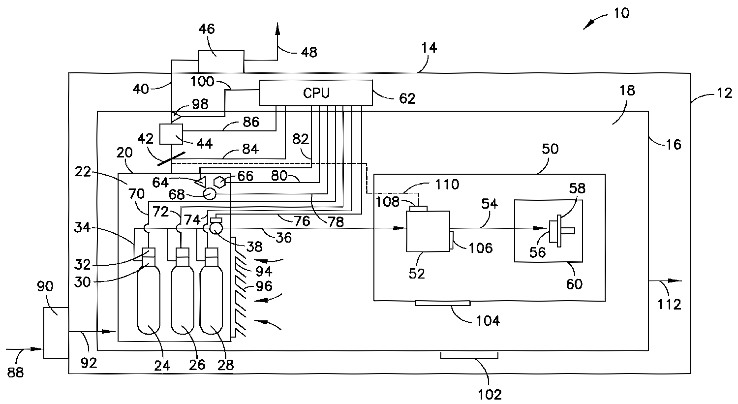
도 1은 본 개시내용의 일 실시예에 따른, 이온 주입 장치를 포함하는 반도체 제조 설비의 간략화된 개략도이다.1 is a simplified schematic diagram of a semiconductor fabrication facility including an ion implantation apparatus, in accordance with one embodiment of the present disclosure;
본 개시내용은 이온 주입 장치 및 방법에 관한 것이다.The present disclosure relates to an ion implantation apparatus and method.
본 개시내용의 이온 주입 시스템 구성은 주입기로부터 외피 배기물을 유동시키고 지금까지 반도체 제조 팹에서 관례였던 바와 같이, 예컨대, 반도체 제조 설비의 옥상 배기부로부터 대기로 이를 배기하는 데 채용되었던 유동 회로의 제거를 가능하게 한다.The ion implantation system configuration of the present disclosure allows for the flow of shell exhaust from the injector and the removal of the flow circuit that has been employed to exhaust it from the rooftop vent of the semiconductor manufacturing facility to the atmosphere, .
외피 배기물은 이온 주입 시스템의 하우징을 통해 유동되고 후속적으로 그것으로부터 배출되는 환기 가스이다. 가스 박스는 이온 주입 시스템의 하우징 내에 배치되고, 가스 박스 외부측에 있는 하우징 내의 가스와 제한된 가스 연통 상태이다. 예를 들어, 가스 박스에는 접근 도어 또는 다른 접근 구조물이 제공되어 예컨대, 접근 도어 내의 루버, 또는 가스 박스의 접근 구조물 또는 구조 부분 내의 다른 가스 통로를 통한 하우징 내의 가스 박스의 외부 환경으로부터 가스 박스 내로의 가스의 진행을 가능하게 할 수 있다. 이온 주입 작업 중, 가스 박스는 가스 박스로부터 환기 가스를 제거하는 역할을 하는 팬 또는 다른 가스-흡인 장비에 의해 배기된다. 음압이 그에 의해 가스 박스 내에 생성되고, 그것은 가스 박스의 "외피측"(외피측은 가스 박스 외부에, 그리고 이온 주입 시스템 하우징 내에 있음)으로부터 가스 박스의 내부 내로 환기 가스를 흡인하는 역할을 한다. 가스-흡인 장비에 의해 가스 박스로부터 제거되는 환기 가스에는 이어서 스크러빙 또는 희석에 의한 처리가 가해져 대기로 배출되고, 한편 외피측 배기물은 이온 주입 장치 하우징으로부터, 이온 주입 장비 설비로부터의 외피측 배기물에 대한 관례였던 바와 같이, 대기로 배출되기보다는 오히려, 예컨대, 이온 주입 시스템이 제공되는 빌딩 내부측의 팹 환경으로 단순하게 배출된다.The shell exhaust is a vent gas that flows through the housing of the ion implantation system and is subsequently exhausted from it. The gas box is disposed within the housing of the ion implantation system and is in a limited gas communication with the gas in the housing on the outside of the gas box. For example, the gas box may be provided with an access door or other access structure, for example, from a louver in an access door, or from an external environment of the gas box in the housing through the access structure of the gas box or other gas passages in the structural part, Thereby enabling the progress of the gas. During the ion implantation operation, the gas box is evacuated by a fan or other gas-suction device that serves to remove the vent gas from the gas box. The negative pressure is thereby created in the gas box, which serves to aspirate the ventilation gas from the "sheath side" of the gas box (the sheath side is outside the gas box and within the ion implantation system housing) into the interior of the gas box. The ventilation gas removed from the gas box by the gas-aspiration equipment is then subjected to scrubbing or dilution treatment to the atmosphere, while the shell-side exhaust is discharged from the ion implantation device housing, Rather than being vented to the atmosphere, as was customary for, for example, the fab environment on the inside of the building where the ion implantation system is provided.
주입기로부터 옥상 배기 시스템으로 외피 배기물을 유동시키는 유동 회로를 제거함으로써, 이온 주입 시스템에 대한 자본적 비용 그리고 또한 동작 비용의 상당한 감소가 성취될 수 있는데, 반도체 제조 설비의 지붕으로 외피 배기물을 이동시키는 덕트워크 및 관련된 팬/송풍기를 설치할 것이 필요하지 않기 때문이다. 나아가, 외피 배기물이 팹 환경으로 복귀되므로, 우선 주변 공기를 흡입하고, 그것에 환기 가스로서의 사용을 위해 여과, 정화, 및 가습/제습을 가하는 데 수반되었던 지출은 단일-통로 방식으로 옥상 배기부로부터 대기로 그것을 단순하게 배출하는 것보다는 오히려 외피 배기물의 재사용에 의해 감소된다. 따라서, 필터, 가습기, 냉각기, 송풍기, 및 관련된 덕트워크를 포함하는, 환기 가스를 위해 사용되는 공기를 보충하는 데 요구되었던 장비는 크기 및 용량 면에서 상당히 감소될 수 있고, 그에 의해 동작 경비의 감소를 성취한다. 구체적인 예로서, 30개의 주입기를 수용하는 팹 내로의 본 개시내용에 따라 구성되는 이온 주입 시스템의 배치는 그러한 설비의 동작 시에 분당 60,000 ft.3 이상의 환기 가스만큼 설비에 대한 환기 가스 요건을 감소시킬 수 있다.By eliminating the flow circuitry that flows the shell exhaust from the injector to the roof exhaust system, a significant reduction in capital cost and also in operating cost for the ion implantation system can be achieved, with the roof of the semiconductor manufacturing facility moving Because it is not necessary to install a ductwork and associated fan / blower. Furthermore, since the shell exhaust is returned to the fab environment, the expenditure incurred first to suck ambient air and to filter, purge, and humidify / dehumidify it for use as a ventilation gas can be accomplished in a single- Rather than simply discharging it into the atmosphere, it is reduced by reuse of the jacketed exhaust. Thus, equipment required to supplement the air used for ventilation gas, including filters, humidifiers, coolers, blowers, and associated ductwork, can be significantly reduced in size and capacity, thereby reducing operating costs . As a specific example, the arrangement of the ion implantation system constructed in accordance with the present disclosure in a fab containing 30 implanters may be such that, in operation of such equipment, 60,000 ft / min. The ventilation gas requirement for the installation can be reduced by as much as three or more ventilation gases.
본 개시내용에 따른 이온 주입 시스템의 구성은 구체적인 실시예들에서 가스 공급 실린더 밸브 헤드 상의 공압 작동기를 이용하는 것, 그리고 가스 박스 내의 가스 공급 실린더로부터의 가스 누출을 나타내는 오염물에 대해 주입기의 외피 환경 및 가스 박스 환경을 감시하고, 그에 의해 누출의 이벤트 시, 감시 및 제어 시스템이 가스 공급 실린더 밸브를 자동적으로 폐쇄하고, 가스 박스 상의 댐퍼를 개방하여 이온 주입기의 통상적인 동작 시에 이용될 수 있는 낮은 체적 가스 유동 속도에 비해, 높은 체적 가스 유동 속도로 가스 박스를 배기하도록 동작하도록 주입기의 감시 및 제어 시스템을 구성하는 것을 포함할 수 있다.The configuration of an ion implantation system in accordance with the present disclosure is based on the use of a pneumatic actuator on the gas supply cylinder valve head in specific embodiments and the use of a sheath environment of the implanter for contaminants indicative of gas leakage from the gas supply cylinder in the gas box, Monitoring the box environment so that at the event of a leak, the monitoring and control system automatically closes the gas supply cylinder valve and opens the damper on the gas box to remove the low volumetric gas that can be used during normal operation of the ion implanter And configuring the monitoring and control system of the injector to operate to exhaust the gas box at a higher volumetric gas flow rate, compared to the flow rate.
가스 공급 실린더는 흡착제-기반 가스 공급 실린더로서, 또는 용기의 내부 체적부 내에 하나 이상의 압력 조절기를 포함하는 압력-조절식 가스 공급 실린더로서, 이온 주입 시스템의 동작의 안전성을 추가로 향상시키도록 구성될 수 있다.The gas supply cylinder is a pressure-regulated gas supply cylinder, either as an adsorbent-based gas supply cylinder or as a pressure regulator in the interior volume of the vessel, which is configured to further improve the safety of the operation of the ion implantation system .
따라서, 본 개시내용에 따른 이온 주입 시스템은 감시 및 제어 시스템이 외피 배기물 내의 임의의 유독성 또는 그렇지 않으면 유해 오염물을 검출할 때, 팹 내로 외피 배기물을 송풍하는 팬을 중지시키고, 가스 박스를 통한 공기유동을 증가시키고 그에 의해 주입기 하우징 내의 외피 가스가 지붕-장착식 또는 다른 처리 장치로의 증가된 배기 속도를 위해 가스 박스 내로 흡인되도록 동작하도록 구성될 수 있다.Thus, the ion implantation system according to the present disclosure can be configured such that when the monitoring and control system detects any poisonous or otherwise harmful contaminants in the shell exhaust, it stops the fan blowing the shell exhaust into the fab, May be configured to operate to increase the air flow and thereby cause the jacket gas in the injector housing to be drawn into the gas box for roof-mounted or increased exhaust speed to other processing devices.
이온 주입 시스템은 구체적인 실시예들에서 주입기 동작 시에 감시 및 제어되는 가스 박스 상의 2-위치 댐퍼로 구성될 수 있다. 이온 주입 시스템이 통상적인 모드로 동작 중이고, 유해 가스가 대기압-아래의 압력으로 가스 박스 내의 가스 소스 용기로부터 공급 중일 때, 감시 및 제어 시스템은 "마이저(miser)/낮은 유동 모드"의 동작으로 주입기를 동작시킨다. 가스 박스 내의 가스 소스 용기가 교환되고 및/또는 기술자가 그렇지 않으면 가스 박스 내에서 작업 중일 때, 감시 및 제어 시스템은 가스 박스가 증가된 속도로 배기되고 여기서 외피 가스가 가스 박스 내로 흡인되고 높은 환기 속도로 지붕-장착식 또는 다른 처리 장치로 배기되는 높은 유동 모드로 주입기를 동작시킨다. 배기 가스는 이온 주입 장치 하우징 내의 도어가 방으로부터의 가스가 하우징 내로 그리고 이어서 이온 주입 장치의 외피로부터 가스 박스 내로 유동하게 하도록 개방되는 곳과 같은, 이온 주입 장비가 놓인 빌딩 내의 방(예컨대, 청정실)으로부터 또한 비롯될 수 있다.The ion implantation system may be comprised of a two-position damper on the gas box that is monitored and controlled in injector operation in specific embodiments. When the ion implantation system is operating in a conventional mode and the noxious gas is being supplied from the gas source container in the gas box at a sub-atmospheric pressure, the monitoring and control system will operate in a "miser / low flow mode" . When the gas source container in the gas box is exchanged and / or the technician is otherwise working in the gas box, the monitoring and control system will vent the gas box at an increased rate, where the enclosure gas is drawn into the gas box and the high ventilation rate Operate the injector in a high flow mode that is exhausted to a roof-mounted or other processing device. The exhaust gas is introduced into a room (e.g., a clean room) in a building in which the ion implantation equipment is placed, such as where the door in the ion implantation apparatus housing is opened to allow gas from the chamber to flow into the housing and then into the gas box from the shell of the ion implantation apparatus. ≪ / RTI >
"스마트" 댐퍼 조립체와 함께 증가된 환기 속도 모드에서 동작하도록 이온 주입 시스템을 구성함으로써, 이온 주입 시스템은 상기 시스템이 통상적인 조건 하에서 낮은 유동 모드의 동작으로 동작할 수 있으므로, 에너지 요건의 상당한 감소를 성취하고, 또한 가스 위험, 예컨대, 유해 가스의 누출, 이벤트 중에 그리고 이온 주입 시스템 내에서의 직원에 의한 보수유지 작업 중에 높은 유동 모드에서 동작하는, 이온 주입 시스템의 안전성 특성의 상당한 향상을 성취한다.By configuring the ion implantation system to operate in an increased ventilation rate mode with a "smart" damper assembly, the ion implantation system is capable of operating in a low flow mode operation under typical conditions, And also achieves a significant improvement in the safety characteristics of the ion implantation system, operating in a high flow mode during gas hazard, e.g., leaking of noxious gases, during events, and during maintenance work by staff in the ion implantation system.
새로운 팹 건설로의 적용에서의 본 개시내용의 접근법은 자본적 장비 비용의 상당한 감소를 가져올 수 있는데, 대기로 또는 그렇지 않으면 팹의 외부로 주입기의 외피 배기물을 배기하는 것을 피할 수 있는 능력이, 대기로 외피 배기물을 배기하는 종래의 접근법이 채용되면 초래되었을 덕트워크, 팬, 공기 정화 시스템 등의 절감을 가능하게 하기 때문이다.The approach of this disclosure in the application of new fab constructions can result in a significant reduction in the capital equipment cost because the ability to avoid venting the jacket exhaust of the injector into or out of the atmosphere, This is because it enables reduction of ductwork, fan, air purification system and the like which would have been caused if the conventional approach of exhausting the casing exhaust to the atmosphere is adopted.
일 양태에서, 본 개시내용은 이온 주입 시스템에 관한 것으로, 이온 주입 시스템은 하나 이상의 가스 공급 용기를 보유하도록 구성되는 가스 박스가 위치되는 포위된 체적부를 형성하는 하우징을 포함하는 이온 주입기로서, 가스 박스는 가스 박스 외부측에 있는 포위된 체적부 내의 가스와 제한된 가스 유동 연통 상태인, 이온 주입기; 하우징을 통해 환기 가스를 유동시키도록 그리고 하우징으로부터 (예컨대, 이온 주입 시스템이 배치되는 팹 빌딩 내의) 이온 주입기의 주변 환경으로 환기 가스를 배기하도록 구성되는 제1 환기 조립체; 처리된, 그리고 무해한, 유출 가스를 생성하기 위해, 가스 박스로부터 가스를, 가스 박스 배기 가스로부터 오염물을 적어도 부분적으로 제거하도록 구성되거나 가스 박스 배기 가스를 희석하도록 구성된 처리 장치로 배기하도록 구성되는 제2 환기 조립체로서, 제2 환기 조립체는 상대적으로 더 낮은 가스 박스 배기 가스 유동 속도와 상대적으로 더 높은 가스 박스 배기 가스 유동 속도 사이에서 가스 박스 배기 가스의 유동 속도를 조정하는 가변 유동 제어 디바이스, 및 가변 유동 제어 디바이스를 통해 가스 박스 배기 가스를 처리 장치로 유동시키도록 구성된 구동 유체 구동기를 포함하는, 제2 환기 조립체; 및 감시 및 제어 조립체로서, 가스 위험 이벤트의 발생에 대해 이온 주입기의 동작을 감시하도록, 그리고 그 때에 하나 이상의 가스 공급 용기의 가스-분배 동작을 대응하여 방지하도록, 그리고 상대적으로 더 높은 가스 박스 배기 가스 유동 속도로 가변 유동 제어 디바이스를 조정하고 그에 의해 구동 유체 구동기가 상대적으로 더 높은 가스 박스 배기 가스 유동 속도로 가스 박스 배기 가스를 처리 장치로 유동시키도록 구성되는, 감시 및 제어 조립체를 포함한다.In one aspect, the present disclosure is directed to an ion implantation system, wherein the ion implantation system includes a housing defining a surrounding volume in which a gas box configured to hold one or more gas supply containers is located, An ion implanter in a limited gas flow communication with gas in the enclosed volume portion on the outside of the gas box; A first ventilation assembly configured to flow ventilation gas through the housing and to vent ventilation gas from the housing to the environment of the ion implanter (e.g., within the fab building in which the ion implantation system is located); And configured to at least partially remove contaminants from the gas box exhaust gas or to exhaust the processing gas to a processing apparatus configured to dilute the gas box exhaust gas to produce a treated, The second ventilation assembly comprising a variable flow control device that adjusts the flow rate of the gas box exhaust gas between a relatively lower gas box exhaust gas flow rate and a relatively higher gas box exhaust gas flow rate, A second ventilation assembly including a drive fluid actuator configured to flow gasbox exhaust through the control device to the processing device; And monitoring and control assemblies for monitoring the operation of the ion implanter for the occurrence of a gas risk event and correspondingly preventing gas-dispensing operations of the one or more gas supply vessels at the time, And a monitoring and control assembly configured to adjust the variable flow control device at a flow rate thereby causing the driving fluid actuator to flow the gas box exhaust gas to the processing device at a relatively higher gas box exhaust gas flow rate.
본 명세서에 사용되는 바와 같이, 용어 "가스 위험 이벤트"는 이온 주입 시스템 또는 그러한 시스템이 배치되는 설비 내의 불충분한 환기 가스 유동 속도의 결과로서 일어나거나 규모 또는 심각성 면에서 증가할 수 있는 임의의 이벤트를 포함하는 것으로 폭넓게 이해되도록 의도된다. 그러한 이벤트는 이온 주입 시스템 내의 유독성이거나 또는 그렇지 않으면 유해 가스 성분의 누출, 예컨대, 도펀트 전달 가스 분배 시스템 내의 누출 또는 고장, 이온 주입 시스템의 장비 또는 구성요소의 과열, 장비 또는 구성요소 오기능 또는 고장, 또는 이온 주입 시스템, 그러한 시스템이 배치되는 설비, 또는 그러한 시스템 또는 설비를 동작시키거나 그렇지 않으면 그것 또는 그것들에 근접한 직원을 해하거나 악영향을 미치는 임의의 다른 사건을, 제한 없이, 포함할 수 있다.As used herein, the term "gas risk event" refers to any event that may occur as a result of an insufficient vent gas flow rate in an ion implantation system or the facility in which such system is located, or may increase in size or severity Are intended to be broadly interpreted as including. Such events may be toxic or otherwise present in the ion implantation system, such as leakage of noxious gas components, such as leaks or failures in the dopant delivery gas distribution system, overheating of the equipment or components of the ion implantation system, Or any other event that causes the ion implantation system, the facility where such a system is deployed, or the operation of such a system or facility, or otherwise disrupts or adversely affects the employee or personnel near it.
본 명세서에 사용되는 바와 같이, 이온 주입기와 관련된 용어 "주변 환경"은 이온 주입기의 하우징의 외부측의 그리고 빌딩 또는 이온 주입기가 배치되는 다른 구조 설비, 예컨대 이온 주입기가 설치되는 청정실 내의 환경을 의미한다.As used herein, the term "ambient environment " associated with an implanter refers to the environment within the clean room where the ion implanter is installed, such as the outside of the housing of the implanter and other building equipment in which the building or ion implanter is located .
위에 폭넓게 기술된 바와 같은 이온 주입 시스템의 하나의 구체적인 실시예에서, 감시 및 제어 조립체는 예컨대, 이온 주입 시스템의 하우징으로부터 외피 배기물을 배출하는 외피 배기 부스터 팬의 동작을 중지시킴으로써 가스 위험 이벤트 시에 제1 환기 조립체의 동작을 종료하도록 구성될 수 있다.In one specific embodiment of the ion implantation system as broadly described above, the monitoring and control assembly may be configured to control the operation of the ion implantation system, for example, by stopping the operation of the shell exhaust ventilation fan that discharges the shell exhaust from the housing of the ion implantation system May be configured to terminate operation of the first ventilation assembly.
이온 주입 시스템은 가변 위치 유동 댐퍼 디바이스, 예컨대, 2-위치 유동 댐퍼 디바이스, 가변 위치 유동 댐퍼 디바이스, 또는 가스 위험 이벤트 시에 가스 박스로부터 높은 체적 유동 속도 배기를 가져오도록 조정될 수 있는 다른 가변 유동 제어 디바이스를 포함하는 가변 유동 제어 디바이스로 구성될 수 있다.The ion implantation system may be a variable position flow damper device, such as a two-position flow damper device, a variable position flow damper device, or other variable flow control device that can be adjusted to bring high volume flow rate exhaust from a gas box at a gas risk event And a variable flow control device including the variable flow control device.
위에-기술된 이온 주입 시스템의 처리 장치는 구체적인 실시예들에서 이온 주입기를 포함하는 팹의 지붕 상의 옥상 처리 유닛을 포함할 수 있다. 그러한 옥상 처리 유닛은 구체적인 실시예들에서 습식 또는 건식 스크러버, 촉매 산화 유닛, 및/또는 가스의 오염물에 대한 수착 친화성을 갖는 흡착제를 포함하고, 그에 의해 가스로부터의 오염물의 제거를 달성한다. 대안적으로, 처리 장치는 처리된 유출 가스를 생성하기 위해, 큰 체적의 공기로 가스 박스 배기 가스를 실질적으로 희석하도록 구성된다.The processing apparatus of the above-described ion implantation system may include a roof top processing unit on the roof of the fab that includes the ion implanter in the specific embodiments. Such rooftop treatment units include adsorbents having sorption affinities for wet or dry scrubbers, catalytic oxidation units, and / or gaseous contaminants in specific embodiments, thereby achieving removal of contaminants from the gas. Alternatively, the treatment apparatus is configured to substantially dilute the gas box exhaust gas with a large volume of air to produce a treated effluent gas.
감시 및 제어 조립체는 마찬가지로 본 개시내용의 폭넓은 실시에서 폭넓게 변동될 수 있다. 감시 및 제어 시스템은 가스 박스 내에 존재할 때에 하나 이상의 가스 공급 용기의 유동 제어 밸브를 작동시키도록 배열되는 공압 밸브 작동기를 포함할 수 있다. 가스 박스는 구체적인 실시예들에서 하나의 가스 공급 용기, 또는 하나 초과의 가스 공급 용기를 수용할 수 있다. 예들 들어, 구체적인 실시예들에서, 이온 주입 작업을 위한 주입 종을 형성하는 이온화를 위한 전구체를 공급하는 도펀트 전구체 공급 용기를 포함하는, 다중의 가스 공급 용기가 존재할 수 있다. 적합한 매니폴딩 및 밸빙 배열에 의해, 배기된 가스 공급 용기로부터 가스 박스 내의 새로운 용기로 가스 분배 동작을 스위칭하도록 구성되는 자동화 스위치-오버 장치를 갖는, 다중의 용기가 존재할 수 있다. 다중의 용기는 공동-유동물, 공동-반응물, 희석제, 세척제 또는 이온 주입 시스템의 동작을 수용하는 다른 가스와 같은, 보조 가스를 수용하는 용기를 포함할 수 있다.Monitoring and control assemblies can likewise be widely varied in a wide variety of implementations of the present disclosure. The monitoring and control system may include a pneumatic valve actuator arranged to operate a flow control valve of one or more gas supply vessels when in the gas box. The gas box may, in specific embodiments, accommodate one gas supply container, or more than one gas supply container. For example, in specific embodiments, there may be multiple gas supply vessels, including a dopant precursor supply vessel that supplies a precursor for ionization to form an implant species for an ion implantation operation. There may be multiple containers with an automated switch-over device configured to switch the gas distribution operation from the evacuated gas supply container to the new container in the gas box, by suitable manifolding and venting arrangements. The multiple vessels may include a vessel for receiving an auxiliary gas, such as a co-feed, a co-reactant, a diluent, a detergent, or other gas to accommodate the operation of the ion implantation system.
가스 공급 용기는 흡착제 상에 저장될 가스에 대한 수착 친화성을 갖고 분배 조건 하에서 그것으로부터 탈착되는 흡착제를 수용하는, 흡착제-기반 용기일 수 있다. 그러한 가스 공급 용기에는 가스 박스 내의 가스 공급 용기의 유동 제어 밸브를 작동시키도록 배열되는 공압 밸브 작동기가 구비될 수 있다. 가스 공급 용기는 대안적으로 압력 조절기의 설정 지점 압력으로, 또는, 직렬 배열의 압력 조절기가 채용될 때, 용기의 밸브 헤드에 가장 근접한 하류의 압력 조절기의 설정 지점 압력으로 용기로부터 가스를 제어가능하게 분배하는, 용기의 내부 체적부 내에 내부적으로 배치되는 하나 이상의 가스 압력 조절기를 갖는, 압력-조절식 가스 공급 용기를 포함할 수 있다. 따라서, 감시 및 제어 조립체는 압력-조절식 가스 공급 용기와 관련되는 공압 밸브 작동기를 포함할 수 있다. 다른 적합한 유형의 가스 공급 용기가 본 개시내용의 폭넓은 실시에서 채용될 수 있다.The gas supply vessel may be an adsorbent-based vessel having a sorption affinity for the gas to be stored on the sorbent and receiving the sorbent desorbed therefrom under dispensing conditions. Such a gas supply vessel may be provided with a pneumatic valve actuator arranged to operate a flow control valve of the gas supply vessel in the gas box. The gas supply container can alternatively control the gas from the vessel to the set point pressure of the pressure regulator or to the set point pressure of the downstream pressure regulator closest to the valve head of the vessel when a series regulating pressure regulator is employed And a pressure-regulated gas supply vessel having at least one gas pressure regulator disposed internally within the interior volume of the vessel for dispensing the gas. Thus, the monitoring and control assembly may include a pneumatic valve actuator associated with a pressure-regulated gas supply container. Other suitable types of gas supply vessels may be employed in the broad practice of this disclosure.
이온 주입 시스템에서 가변 유동 제어 디바이스를 통해 처리 장치로 가스 박스 배기 가스를 유동시키는 데 이용되는 구동 유체 구동기는 임의의 적합한 유형을 가질 수 있고, 가변 구동기 송풍기 또는 팬을 포함할 수 있다. 구동 유체 구동기는 가변 주파수 구동기를 포함할 수 있다.The drive fluid actuator used to flow the gas box exhaust gas through the variable flow control device in the ion implantation system to the processing apparatus may have any suitable type and may include a variable driver blower or fan. The driving fluid actuator may include a variable frequency driver.
다양한 배열의 감시 및 제어 조립체가 채용될 수 있다. 다양한 실시예들에서, 하나 이상의 센서가 포위부(가스 박스의 내부측 및/또는 외부측) 내의 공정 조건(들)을 감지하도록, 그리고 하나 이상의 센서의 공정 조건 감지를 기초로 하여 가변 유동 제어 디바이스를 대응하여 조정하도록 구성될 수 있다. 그러한 센서는 압력 센서, 온도 센서, 유독 가스 모니터, 또는 다른 감지 또는 검출 디바이스 또는 조립체를 포함할 수 있다. 가장 안전한 모드의 이온 주입 시스템 동작은 대기압-아래의 압력으로의 가스 전달을 수반한다. 센서는 가스 공급 파이핑을 감시하고, 가스 공급 라인 내의 감시된 압력이 미리결정된 최대 수치를 초과하거나, (성질상 유해하지 않은 작은 압력 변동을 수용하도록) 가스 공급 라인 내의 압력의 미리 결정된 변화 속도를 초과할 때에 경보 출력 또는 유동 종료 출력 신호를 발생시키는 압력 센서를 대응하여 포함할 수 있다.Various arrangements of monitoring and control assemblies can be employed. In various embodiments, one or more sensors may be used to sense the process condition (s) in the enclosure (the inner side and / or the outer side of the gas box), and the variable flow control device As shown in FIG. Such sensors may include pressure sensors, temperature sensors, toxic gas monitors, or other sensing or sensing devices or assemblies. The operation of the ion implantation system in the safest mode involves gas transfer to atmospheric-to-subatmospheric pressure. The sensor monitors the gas supply piping, and exceeds the predetermined rate of change in pressure in the gas supply line so that the monitored pressure in the gas supply line exceeds a predetermined maximum value or (to accommodate small pressure fluctuations that are not detrimental to nature) A pressure sensor for generating an alarm output or a flow termination output signal at the time of the start of the operation.
이온 주입 시스템은 그것 자체가 다양하게 구성될 수 있고, 빔 라인 이온 주입 장비, 또는 플라즈마 침지 이온 주입 장비, 또는 다른 유형의 이온 주입 장비를 포함할 수 있다. 다양한 실시예들에서, 이온 주입 시스템 내의 이온 주입기는 이온 소스 챔버로서, 이온 소스 챔버와 가스-분배 가스 공급 용기(들)를 상호연결하는 가스 유동 회로를 통한 분배된 가스의 유동에 의해, 가스 박스 내의 하나 이상의 가스 공급 용기 중 적어도 하나로부터 가스를 수용하도록 배열되는, 이온 소스 챔버를 포함할 수 있다.The ion implantation system itself may be variously configured and may include a beamline ion implantation device, or a plasma immersion ion implantation device, or other type of ion implantation device. In various embodiments, the ion implanter in the ion implantation system is an ion source chamber, which, by the flow of the dispensed gas through the gas flow circuit interconnecting the ion source chamber and the gas-dispensing gas supply vessel (s) The chamber being configured to receive gas from at least one of the one or more gas supply vessels within the chamber.
감시 및 제어 조립체는 그러한 이온 주입 시스템에서 전술된 가스 위험 이벤트로서, 하나 이상의 공정 조건이 미리결정된 공정 조건(들)으로부터 이탈하는 이벤트 시에 가스-분배 가스 공급 용기(들)로부터의 가스-분배 동작을 방지하도록 배열될 수 있다. 감시 및 제어 조립체는 예들 들어 전술된 가스 위험 이벤트로서, 가스 박스 내의 압력이 대기압-아래의 압력 조건으로부터 이탈할 때에 가스-분배 가스 공급 용기(들)로부터의 분배된 가스의 유동을 종료하도록 구성될 수 있다. 감시 및 제어 조립체는 이어서 가스-분배 가스 공급 용기(들)의 가스 공급 밸브를 제어하도록 및/또는 유동 회로 내의 가스 유동 제어 밸브(들)를 폐쇄하도록 밸브 작동기를 작동시킴으로써 분배된 가스의 유동을 종료할 수 있다.The monitoring and control assembly may be a gas risk event as described above in such an ion implantation system, such as a gas-dispensing operation from the gas-dispensing gas supply vessel (s) in the event of one or more process conditions deviating from the predetermined process condition . ≪ / RTI > The monitoring and control assembly may be configured to terminate the flow of the dispensed gas from the gas-dispensing gas supply vessel (s), for example, when the pressure in the gas box leaves the atmospheric-pressure condition . The monitoring and control assembly then terminates the flow of the dispensed gas by actuating the valve actuator to control the gas supply valve of the gas-dispensing gas supply container (s) and / or to close the gas flow control valve (s) in the flow circuit can do.
따라서, 감시 및 제어 조립체는 가스 박스 내의 하나 이상의 가스 공급 용기로부터의 가스의 분배 중에 대기압-아래의 압력으로 가스 박스를 유지하도록 구성될 수 있다.Thus, the monitoring and control assembly can be configured to maintain the gas box at sub-atmospheric pressure during distribution of the gas from one or more gas supply vessels in the gas box.
다양한 실시예들에서, 이온 주입 시스템은 가스 박스가 가스 박스 내의 가스 공급 용기의 설치 또는 교환을 허용하도록 개방가능하고, 동작을 위해 가스 박스를 구성하도록 폐쇄가능한 접근 구조물을 포함하도록 구성될 수 있고, 감시 및 제어 조립체는 가스 박스 접근 구조물이 개방될 때, 상대적으로 더 높은 가스 박스 배기 가스 유동 속도로 가변 유동 제어 디바이스를 조정하고 그에 의해 구동 유체 구동기가 상대적으로 더 높은 가스 박스 배기 가스 유동 속도로 가스 박스 배기 가스를 처리 장치로 유동시키도록 구성된다.In various embodiments, the ion implantation system may be configured to include a closureable access structure for opening the gas box to allow installation or replacement of the gas supply container in the gas box and for configuring the gas box for operation, The monitoring and control assembly adjusts the variable flow control device to a relatively higher gas box exhaust gas flow rate when the gas box approach structure is opened and thereby allows the drive fluid actuator to operate at a relatively higher gas box exhaust gas flow rate And to flow the box exhaust gas to the processing apparatus.
그러한 배열은 가스 박스로의 접근 또는 보수유지, 검사, 가스 공급 용기의 가스 박스 내로의 리로딩, 및 다른 접근 활동을 요구하는 작업자에게 고도의 안전성을 제공한다.Such an arrangement provides a high degree of safety to workers requiring access to or maintenance of the gas box, inspection, re-loading of the gas supply vessel into the gas box, and other access activities.
다른 실시예들에서, 이온 주입 시스템은 제2 환기 조립체와 이온 주입 시스템의 진공 챔버를 상호연결하여 진공 챔버를 작업, 검사, 또는 보수유지 직원에 의한 그것의 접근 중에 배기하도록 선택적으로 결합가능한 가스 유동 라인을 포함하는 감시 및 제어 조립체로 구성될 수 있다. 이러한 목적을 위해, 진공 챔버는 진공 챔버로의 가스 유동 라인의 결합을 가능하게 하는 선택적 제거가능 커버를 포함할 수 있다.In other embodiments, the ion implantation system includes a gas flow that selectively interconnects the second ventilation assembly and the vacuum chamber of the ion implantation system to evacuate the vacuum chamber during its approach by a work, inspection, or maintenance personnel And a monitoring and control assembly including a line. For this purpose, the vacuum chamber may comprise a selectively removable cover which allows the joining of the gas flow lines to the vacuum chamber.
다른 실시예들에서, 이온 주입 시스템은 가스 위험 이벤트의 발생 시에 제1 환기 조립체의 동작을 종료하도록 구성되는 감시 및 제어 조립체를 포함할 수 있다. 제1 환기 조립체는 수반되는 구체적인 적용분야에 적합한 것으로서, 외피 배기 송풍기, 팬, 및/또는 다른 환기 장비를 포함할 수 있다.In other embodiments, the ion implantation system may include a monitoring and control assembly configured to terminate operation of the first ventilation assembly upon occurrence of a gas risk event. The first ventilation assembly is suitable for the specific application to which it is associated and may include a cow vent fan, fan, and / or other ventilation equipment.
이온 주입 시스템은 다른 실시예들에서 가스 위험 이벤트의 발생이 가스 박스 내의 환기 가스 내의 또는 하우징 내의 환기 가스 내의 유해 가스의 감시 및 제어 조립체에 의한 검출을 포함하도록 구성될 수 있다.The ion implantation system may be configured in other embodiments to include the detection of a hazardous gas event within the vent gas within the gas box or by the monitoring and control assembly of the noxious gas in the vent gas within the housing.
이온 주입 시스템은 가스 처리 설비에 직접적으로 또는 간접적으로 연결되지 않는 제1 환기 조립체로 구성될 수 있다.The ion implantation system may be comprised of a first ventilation assembly that is not directly or indirectly connected to the gas treatment facility.
상기 개시내용은 또 다른 양태에서 본 명세서에 다양하게 기술된 바와 같은 상기 개시내용의 이온 주입 시스템을 포함하는 반도체 제조 설비로서, 여기서 처리 장치는 설비의 지붕 상의 옥상 처리 유닛을 포함하는, 반도체 제조 설비에 관한 것이다. 그러한 반도체 제조 설비는 설비가 외피 배기물의 옥상 배기를 위한 어떠한 덕트워크도 포함하지 않도록 구성될 수 있다.The disclosure is directed to a semiconductor fabrication facility comprising an ion implantation system of the disclosure as described in detail herein in another aspect, wherein the processing apparatus is a semiconductor fabrication facility, including a roof top processing unit on the roof of the facility, . Such a semiconductor manufacturing facility may be configured such that the facility does not include any ductwork for roof venting of the jacketed exhaust.
또 다른 양태에서, 상기 개시내용은 이온 주입기를 포함하는 이온 주입 시스템을 동작시키는 방법에 관한 것으로, 이온 주입기는 하나 이상의 가스 공급 용기를 보유하도록 구성되는 가스 박스가 위치되는 포위된 체적부를 형성하는 하우징을 포함하고, 가스 박스는 가스 박스 외부측에 있는 포위된 체적부 내의 가스와 제한된 가스 유동 연통 상태이며, 그러한 방법은 하우징을 통해 환기 가스를 유동시키고, 하우징으로부터 이온 주입기의 주변 환경으로 환기 가스를 배기하는 단계; 처리된 유출 가스를 생성하기 위해, 가스 박스로부터 가스를 배기하고, 가스 박스 배기 가스로부터 오염물을 적어도 부분적으로 제거하도록, 또는 가스 박스 배기 가스를 희석하도록 가스를 처리하는 단계; 가스 위험 이벤트의 발생에 대해 이온 주입기의 동작을 감시하는 단계; 상기 감시 중의 가스 위험 이벤트의 비-발생 중, 상기 처리를 위해 가스 박스로부터 가스를 상대적으로 더 낮은 가스 박스 배기 유동 속도로 배기하는 단계; 및 상기 감시 중의 가스 위험 이벤트의 발생 시, 하나 이상의 가스 공급 용기의 가스-분배 동작을 방지하고, 상기 처리를 위해 가스 박스로부터 가스를 상대적으로 더 높은 가스 박스 배기 유동 속도로 배기하는 단계를 포함한다.In another aspect, the disclosure relates to a method of operating an ion implantation system including an ion implanter, the ion implanter comprising a housing defining an enclosed volume in which a gas box configured to hold one or more gas supply containers is located, Wherein the gas box is in a limited gas flow communication with the gas in the enclosed volume portion on the outside of the gas box, the method comprising the steps of flowing a vent gas through the housing and venting the vent gas from the housing to the environment of the implanter Evacuating; Treating the gas to evacuate gas from the gas box and at least partially remove contaminants from the gas box exhaust gas to dilute the gas box exhaust gas to produce a treated effluent gas; Monitoring the operation of the ion implanter for the occurrence of a gas risk event; Evacuating gas from the gas box at a relatively lower gas box exhaust flow rate for the process during non-occurrence of the monitored gas hazard event; And preventing gas-dispensing operation of the one or more gas supply vessels at the occurrence of the monitored gas risk event and venting gas from the gas box to a relatively higher gas box exhaust flow rate for the treatment .
이러한 방법은 가스 위험 이벤트의 발생 시, 하우징을 통한 환기 가스의 유동, 및 하우징으로부터 이온 주입기의 주변 환경으로의 환기 가스의 배기가 종료되는 방식으로 실시될 수 있다.This method can be implemented in such a manner that, when a gas risk event occurs, the flow of the ventilation gas through the housing and the exhaust of the ventilation gas from the housing to the surrounding environment of the ion implanter are terminated.
전술된 방법에서의 처리는 이온 주입기를 포함하는 팹의 지붕 상의 옥상 처리 유닛 내에서의 가스 처리를 포함할 수 있다.The processing in the above-described method may include gas treatment in the roof top processing unit on the roof of the fab including the ion implanter.
위에 폭넓게 기술된 방법에서, 하나 이상의 가스 공급 용기의 각각은 그것에 동작가능하게 결합되는 공압 밸브 작동기를 가질 수 있고, 여기서 공압 밸브 작동기는 가스-분배 동작의 방지를 위해 작동된다. 이전에 기술된 바와 같은 용기는 하나 이상의 흡착제-기반 가스 공급 용기, 또는 하나 이상의 압력 조절식 가스 공급 용기, 또는 둘 모두의 유형의, 또는 다른 유형의 용기를 포함할 수 있다.In the method broadly described above, each of the one or more gas supply vessels may have a pneumatic valve actuator operatively coupled thereto, wherein the pneumatic valve actuator is operated to prevent gas-dispensing operations. A vessel as previously described may comprise one or more adsorber-based gas supply vessels, or one or more pressure regulated gas supply vessels, or both types, or other types of vessels.
전술된 방법에서의 감시 동작은 가스 박스의 외부측의 포위부 내의 공정 조건(들)을 감시하는 단계를 포함할 수 있다. 감시 동작은 압력 감시, 온도 감시, 유독 가스의 검출을 위한 감시, 및/또는 임의의 다른 감시 동작을 포함할 수 있다.The monitoring operation in the above-described method may include monitoring the process condition (s) in the surrounding portion on the outer side of the gas box. Monitoring operations may include pressure monitoring, temperature monitoring, monitoring for detection of toxic gases, and / or any other monitoring operation.
상기 개시내용의 폭넓게 기술된 방법은 전술된 가스 위험 이벤트로서, 하나 이상의 공정 조건이 미리결정된 공정 조건으로부터 이탈하는 이벤트 시에 하나 이상의 가스 공급 용기의 가스-분배 동작을 방지하는 단계를 포함할 수 있다. 예들 들어, 상기 방법은 그러한 가스 위험 이벤트로서, (예컨대, 도펀트 가스 전달 라인 내의) 감시된 압력이 대기압-아래의 압력 조건으로부터 이탈할 때에 하나 이상의 가스 공급 용기의 가스-분배 동작을 방지하는 단계를 포함할 수 있다.The broadly described method of the disclosure may include preventing the gas-dispensing operation of one or more gas supply vessels in the event that one or more process conditions deviate from predetermined process conditions, . For example, the method may include, as such a gas risk event, preventing the gas-dispensing operation of the one or more gas supply vessels when the monitored pressure (e.g., in the dopant gas delivery line) leaves the atmospheric- .
하나 이상의 가스 공급 용기의 가스-분배 동작의 방지는 가스-분배 가스 공급 용기(들)의 가스 공급 밸브의 폐쇄에 의해 및/또는 하나 이상의 가스 공급 용기와 관련되는 유동 회로 내의 가스 유동 제어 밸브(들)의 폐쇄에 의해 유발될 수 있다.The prevention of the gas-dispensing operation of the one or more gas supply vessels may be facilitated by the closing of the gas supply valves of the gas-dispensing gas supply vessel (s) and / or the gas flow control valves (s) in the flow circuit Lt; / RTI >
상기 방법은 가스 박스 내의 하나 이상의 가스 공급 용기로부터의 가스의 분배 중에 대기압-아래의 압력으로 가스 박스를 유지하도록 실시될 수 있다.The method may be practiced to maintain the gas box at atmospheric-subatmospheric pressure during distribution of the gas from one or more gas supply vessels in the gas box.
위의 기술에 따르면, 가스 박스는 가스 박스 내의 가스 공급 용기의 설치 또는 교환을 허용하도록 개방가능하고, 동작을 위해 가스 박스를 구성하도록 폐쇄가능한 접근 구조물을 포함할 수 있고, 여기서 상기 방법은 가스 박스 접근 구조물이 개방될 때, 상대적으로 더 높은 가스 박스 배기 가스 유동 속도로 가스 박스로부터 가스를 배기하는 단계를 포함한다.According to the above description, the gas box may be openable to allow installation or exchange of the gas supply container in the gas box and may include a closeable access structure for constructing the gas box for operation, And venting the gas from the gas box at a relatively higher gas box exhaust gas flow rate when the access structure is opened.
상기 개시내용의 폭넓게 기술된 방법은 진공 챔버를 포함하는 이온 주입 시스템에서 수행될 수 있고, 상기 방법은 가스 박스로부터 가스를 배기하는 덕트워크로 진공 챔버를 배기하고, 가스를 진공 챔버로부터 처리 동작부로 배기하는 단계를 포함한다.The broadly described method of the disclosure can be performed in an ion implantation system including a vacuum chamber, which evacuates the vacuum chamber to a ductwork that evacuates gas from the gas box and transfers the gas from the vacuum chamber to the processing chamber And exhausting the exhaust gas.
따라서, 상기 방법은 다양한 실시예들에서 가스 위험 이벤트의 발생 시, 하우징을 통한 환기 가스의 유동 및 하우징으로부터 이온 주입기의 주변 환경(예컨대, 이온 주입 시스템이 배치되는 방 또는 빌딩)으로의 환기 가스의 배기를 종료하는 단계를 포함하는 것으로서 수행될 수 있다. 가스 위험 이벤트의 발생은 가스 박스 내의 환기 가스(가스 박스 배기물) 내의 유해 가스를 검출하는 단계 및/또는 하우징 내의 환기 가스(외피 배기물) 내의 유해 가스를 검출하는 단계를 포함할 수 있다.Thus, the method can be used to control the flow of ventilation gas through the housing and the flow of ventilation gas from the housing to the surrounding environment of the implanter (e.g., the room or building in which the ion implantation system is located) And terminating the evacuation. The occurrence of the gas risk event may include detecting the noxious gas in the vent gas (gas box exhaust) in the gas box and / or detecting the noxious gas in the vent gas (shell exhaust) in the housing.
도면을 이제 참조하면, 도 1은 지붕(14)을 갖는 팹 빌딩(12)을 포함하는 반도체 제조 설비(10)의 개략도이다. 빌딩 내에는 이온 주입 시스템 하우징(16)으로서, 그것 내에 내부 체적부(18)를 형성하는, 이온 주입 시스템 하우징(16)을 포함하는 이온 주입 시스템이 배치된다. 하우징(16)의 내부 체적부(18) 내에는 가스 박스(20)가 제공되고, 그것 내에 내부 체적부(22)를 형성한다.Referring now to the drawings, FIG. 1 is a schematic diagram of a
가스 박스(20)의 내부 체적부(22)는 가스 공급 용기(24, 26, 28)를 수용한다. 가스 공급 용기의 각각은 관련된 공압 작동기(32)에 의해 완전 개방 위치와 완전 폐쇄 위치 사이에서 선택적으로 전환가능한 밸브를 수용하는 밸브 헤드(30)를 포함한다. 각각의 용기의 밸브 헤드의 각각은 가스 분배 라인(34)과 결합되고, 각각의 가스 분배 라인은 매니폴드 배열로 분배된 가스 급송 라인(36)에 연결된다. 분배된 가스 급송 라인(36)은 개방될 때에 가스 공급 용기들 중 하나 이상에 의해 공급되는 가스가 이온 소스 챔버(52)로 유동되게 하는, 매니폴드 분리 밸브(38)를 수용한다.The
가스 박스(20)에는 가변 위치 댐퍼(42) 및 가스 박스 배기 송풍기(44), 그리고 또한 배기 덕트 온도 센서(98)를 수용하는 가스 박스 배기 덕트(40)가 제공된다. 가스 박스 배기 덕트(40)는 가스 박스(20) 내부 체적부(22)로부터 옥상 처리 유닛(46)으로 가스 박스 배기 가스를 운반하고, 옥상 처리 유닛에서 가스 박스 배기 가스는 그것으로부터 오염물을 제거하도록 처리되고 및/또는 큰 체적의 공기로 가스 박스 배기 가스를 희석하도록 처리되고, 그에 의해 배기 라인(48)에서 대기로 배출되는 처리된 가스를 생성한다.The
옥상 처리 유닛(46)은 그에 따라 가스 박스 배기 가스로부터 그것이 배기 라인(48)에서 대기로 배출될 수 있도록 오염물을 제거하는 촉매 산화 유닛, 가스 박스 배기 가스와 접촉하는 흡수제 베드, 습식 또는 건식 스크러버 등을 포함할 수 있다. 옥상 처리 유닛(46)은 대안적으로 또는 추가적으로 팹 빌딩 외부측으로부터의 공기로 가스 박스 배기물을 희석하는 흡기 배열체를 포함할 수 있다.The
이온 주입 시스템 하우징(16)의 내부 체적부(18)는 전술된 이온 소스 챔버(52)를 포함하는 이온 주입 장비(50)를 수용한다. 이온 주입 장비(50)는 보수유지, 검사 등을 위한 접근 도어(104)를 포함한다. 상기 장비의 이온 소스 챔버(52)는 이온 주입 시스템의 동작 중에 진공 챔버로서 진공 하에서 동작되고, 그것에는 보수유지, 검사 등을 위한 접근 도어(106)가 제공된다. 이온 소스 챔버(52)에는 가요성 배기 라인(110)이 결합될 수 있는, 제거가능 커버(108)가 제공될 수 있고, 여기서 그러한 가요성 배기 라인의 대향 단부는 보수유지 중에 이온 소스 챔버(52)를 배기하도록 가스 박스 배기 덕트(40)에 결합가능하고, 예컨대, 여기서 접근 도어(102, 104, 106)는 팹 공기가 이온 소스 챔버 내로 흡인되고 가스 박스 배기 덕트(40)를 통해 배기되게 하도록 개방된다.The
이온 주입 장비(50) 내의 이온 소스 챔버(52)는 분배된 가스 급송 라인으로부터 그것으로 유동되는 가스 내의 전구체로부터, 그러한 가스의 이온화에 의해, 주입 종을 발생시키도록 동작하도록 구성되고, 이온 소스 챔버는 주입 챔버(60) 내의 지지체(58) 상의 기판(56) 상에 충돌되도록 유도되는 이온 빔(54)의 발생을 위한 전극, 원자 질량 단위 선택 장비, 시준 구성요소 등(도 1에 도시되지 않음)과 관련된다.The
반도체 제조 설비(10)는 보급 공기가 여과, 가습/제습, 정화, 및 온도 조정되는 보급 공기 처리 유닛(90) 내로 주변 공기를 유입시켜 외피 환기 가스 입구 라인(92)을 거쳐 이온 주입 시스템 하우징(16)의 내부 체적부(18) 내로 유입되는 환기 가스를 제공하는 보급 공기 입구 라인(88)을 포함한다. 이러한 외피 배기물은 이어서 하우징의 내부 체적부(18)를 통해 유동하고, 가스 박스 접근 도어(94) 내의 루버(96)를 통해 가스 박스 내로 흡인된다. 가스 박스(20)의 내부 체적부(22) 내로 진입하는 환기 가스는 옥상 처리 유닛으로의 유동을 위해 배기 덕트(40) 내로 가스 박스 배기 가스로서 환기 가스를 흡인하는 역할을 하는, 가변 속도 방식을 가질 수 있는, 가변 위치 댐퍼(42) 및 가스 박스 배기 송풍기(44)에 의해 제어되는 속도로 가스 박스 배기 덕트(40)로 배기된다. 이온 주입 시스템 하우징(16)의 내부 체적부(18)로 유입되는 환기 가스는 그러한 내부 체적부를 통한 유동 후, 가스 박스(20) 내로 흡인되는 체적을 제외하면, 외피 배기 라인(112)에 의해 팹으로 배출된다.The
도 1에 도시된 이온 주입 시스템에는 상기 시스템의 동작에 대한 감시 및 제어 조립체가 제공된다. 그러한 감시 및 제어 조립체는 가스 박스의 내부 체적부(22) 내의 감시 구성요소에 동작가능하게 연결되는 CPU(62)를 포함한다. 그러한 감시 구성요소는 온도 감지 신호 전송 라인(82)에 의해 CPU(62)에 신호 전송 관계로 결합되는 온도 센서(64)를 포함한다. 감시 구성요소는 압력 감지 신호 전송 라인(80)에 의해 CPU(62)에 신호 전송 관계로 결합되는 압력 센서(66)를 포함한다. 감시 구성요소는 예컨대, 가스 공급 용기 또는 매니폴드 커플링으로부터의 누출의 결과로서 유해 가스의 존재를 검출하도록 구성되는 유독 가스 모니터(68)를 또한 포함한다. 유독 가스 모니터는 유독 가스 모니터 신호 전송 라인(78)에 의해 CPU(62)에 신호 전송 관계로 결합된다. 임의의 개수 및 유형의 감시 구성요소가 상기 개시내용의 실시에서 이용되고, 그에 의해 CPU로 각각의 신호 전송 라인에 의해 전송되는 출력을 발생시키고, 그것들에 대응하여 CPU가 이온 주입 시스템 내의 장비 및 공정 조건을 조정하여 그것의 효율적인 동작을 성취할 수 있다는 것이 이해될 것이다.The ion implantation system shown in Figure 1 is provided with a monitoring and control assembly for operation of the system. Such monitoring and control assembly includes a
예시된 바와 같은 CPU(62)는 다양한 시스템 요소로 출력 제어 신호를 전송하도록 구성될 수 있다. 예를 들어, CPU는 가스 공급 용기와 관련되는 각각의 공압 밸브 작동기로 신호 전송 라인(70, 72, 74)에서 제어 신호를 전송함으로써 가스 위험 이벤트를 지시하는 입력된 감지 신호에 대응하고, 그에 의해 그러한 가스 공급 용기의 밸브 헤드 내의 각각의 밸브를 폐쇄하도록 구성될 수 있다. CPU는 추가적으로 매니폴드 분리 밸브(38)로의 신호 전송 라인(76)에서의 제어 신호의 전송에 의해 가스 급송 매니폴드를 분리하고, 그에 의해 밸브가 가스 위험 이벤트에 대응하여 폐쇄되도록 신호되도록 구성될 수 있다.The
CPU(62)는 가스 박스 배기 송풍기(44)로의 신호 전송 라인(86)에서의 제어 신호의 CPU에 의한 전송과 연계하여, 가변 위치 댐퍼(42)로 신호 전송 라인(84)에서 제어 신호를 전송하여 그러한 댐퍼를 개방하고 증가된 배기 유동을 용이하게 하고 그에 의해 가스 박스(20)의 내부 체적부(22)로부터의 가스의 고속 배기가 성취되도록 또한 구성될 수 있다. 도 1의 예시된 실시예에서의 가스 박스(20)가 다양한 센서 요소를 수용하는 것으로서 도시되지만, 대응 요소가 또한 예컨대, CPU(62)로 신호 전송 라인(100)에서 배기 덕트 온도 신호를 출력하도록 배열되는, 배기 덕트 온도 센서(98)에 의해 예시된 바와 같이 가스 박스 배기 덕트(40) 내에 위치될 수 있다는 것이 이해될 것이다.The
따라서, CPU(62)는 이온 주입 시스템 내의 동작 및 공정 조건을 지시하는 다양한 감지 데이터를 수용하도록, 그리고 대응하여 가변 위치 댐퍼(42) 및 가스 박스 배기 송풍기(44)를 제어가능하게 조정하여 가스 위험 이벤트의 발생 시에 상승된 가스 박스 배기 유동 속도를 가져오도록, 그리고 가스 공급 용기 상의 밸브의 폐쇄 및/또는 가스 공급 매니폴드 유동 회로 내의 분리 밸브(38)의 폐쇄에 의해 가스 박스 내의 가스 공급 용기로부터의 가스의 분배를 종료하도록 구성된다.Accordingly, the
이온 주입 시스템은 접근 도어(94, 102, 104, 106) 중 하나 이상이 작업, 검사, 또는 보수유지 직원에 의해 개방될 때에 가스 박스 배기 유동을 증가시키고, 그에 의해 가스 박스 배기 유동 속도가 즉시 상승되어 그러한 접근 활동의 안전성을 향상시키는 역할을 하는 CPU로 또한 구성될 수 있다.The ion implantation system increases the gas box exhaust flow when one or more of the
가변 위치 댐퍼(42)는 그에 따라 종료점 위치들 사이에서 완전히 연속적으로 가변하는 것으로서 구성될 수 있거나, 그것은 둘 이상의 별개의 위치 설정에 대해 구성될 수 있고, 그에 의해 가스 박스 배기 가스 유동 속도가 통상적인 동작 조건 및 가스 위험 이벤트 조건에 맞게 조정될 수 있지만, 어느 경우에나, 가스 박스 배기 가스 유동 속도는 이온 주입 시스템의 통상적인(즉, 비-위험 이벤트) 동작 조건에 수반되는 상대적으로 더 낮은 수준에 비해, 가스 위험 이벤트의 발생 시에 상대적으로 더 높은 수준으로 상승된다.The
본 개시내용의 폭넓은 실시에서 이용되는 감시 및 제어 조립체는 폭넓은 범위의 감시 활동 및 대응 제어 행동을 제공하여 이온 주입 시스템의 안전성 및 효율을 향상시키도록 폭넓게 변동될 수 있다는 것이 이해될 것이다.It will be appreciated that the monitoring and control assemblies utilized in the broad practice of this disclosure can be widely varied to provide a wide range of monitoring and countering control behaviors to enhance the safety and efficiency of the iontophoretic system.
본 개시내용의 이온 주입 배기 관리 장치 및 공정은 본 개시내용의 배기 관리 장치 및 공정을 이용하지 않는 이온 주입 시스템에 비해, 상당한 감소가 이온 주입 시스템의 에너지 및 자본적 장비 비용 면에서 성취될 수 있게 한다. 본 개시내용의 장치 및 공정은 더 안전한, 덜 비싼 주입 시스템 공기 취급을 제공하고, 반도체 제조 작업에서 온실 가스 방출을 최소화하는 것을 돕는다.The ion implantation exhaust management apparatus and process of the present disclosure is advantageous in that significant reductions can be achieved in terms of energy and capital equipment costs of the ion implantation system as compared to ion implantation systems that do not utilize the exhaust management apparatus and processes of the present disclosure do. The apparatus and processes of the present disclosure provide safer, less expensive injection system air handling and help to minimize greenhouse gas emissions in semiconductor manufacturing operations.
반도체 설비 내의 다른 제조 장비에 비해, 이온 주입기는 가스 박스와 수용 외피 포위부 사이에서 분리되는, 전형적으로 2500 CFM 정도의 총 환기량을 사용하는, 최대 배기 체적을 요구한다. 종래의 반도체 팹이 30+개의 주입기를 수용할 수 있다는 점을 고려하면, 이러한 체적의 청정하고, 고도로 조절된 공기를 교체하는 데 필요한 에너지는 상당하고, 큰 기반시설 지출을 요구한다. 유해 물질을 잠재적으로 함유하는, 가스 박스 배기물은 전형적으로 방출되기 전에 스크러버를 통해 보내진다. 스크러빙된(또는 산) 배기물은, 그에 따라, 외피 배기물보다 많은 자원을 소모하고, 팹 작업의 비용에 더 많이 기여한다.Compared to other manufacturing equipment in semiconductor equipment, the ion implanter requires a maximum exhaust volume, typically using a total ventilation volume of about 2500 CFM, which is separated between the gas box and the enclosure enclosure. Considering that conventional semiconductor fabs can accommodate 30+ injectors, the energy required to replace this volume of clean, highly regulated air is substantial and requires significant infrastructure expenditure. Gas box exhausts, potentially containing hazardous substances, are typically sent through the scrubber before being released. The scrubbed (or acid) exhaust thus consumes more resources than the shell exhaust and contributes more to the cost of the fab operation.
본 개시내용은 반도체 제조 설비의 가변 및 자본적 비용이 주입기 동작과 관련되는 배기된 공기 체적의 상당량의 재사용에 의해 감소될 수 있고, 실시예들이 배기 요건을 추가로 감소시키고 이온 주입기의 동작 아키텍처 내로 환기 관리를 통합하여 증가된 효율 및 안정성을 성취하도록 접근한다는 것을 인식한다.The present disclosure is based on the finding that the variable and capital costs of semiconductor manufacturing facilities can be reduced by reusing a significant amount of exhausted air volume associated with injector operation and that embodiments further reduce exhaust requirements and reduce Recognize that approaches to integrate ventilation management to achieve increased efficiency and stability.
본 개시내용은 증가된 지구 온난화 문제 및 에너지 비용을 상승시키는 일반적인 경향에 대응하여, 반도체 제조업자가 공격적인 에너지 감소 계획을 채택하여 경쟁력을 유지하여야 한다는 것을 또한 인식한다. 동시에, 팹 설계자는 팹 용량 확장 및 신규개발(greenfield) 프로젝트의 자본적 비용을 감소시키려는 지속적인 압력 하에 있다. 이러한 상황에서, 개선된 이온 주입 배기 관리가 효과적인 에너지 및 비용 감소 전략이다.The present disclosure also recognizes that semiconductor manufacturers must remain competitive in adopting an aggressive energy reduction plan in response to the increasing global warming problem and the general tendency to increase energy costs. At the same time, fab designers are under constant pressure to expand the capacity of the fab and reduce the capital cost of greenfield projects. In this situation, improved ion implantation management is an effective energy and cost reduction strategy.
이온 주입 장비는 전형적으로 2개의 배기 포위부, 즉 가스 박스 및 외측 수용 외피를 포함한다. 장비 설계에 따라, 말단 포위부 내에 또는 외측 수용 외피 내에 단독으로 위치되는, 가스 박스 포위부는 도펀트 가스 실린더 및 관련된 유동 제어 및 감시 장비를 수용한다. 가스 박스 배기 유동 속도는 가압 가스 누출의 이벤트 시에 최소 면 속도 및 희석을 유지하도록 300 cfm 내지 500 cfm의 범위를 가질 수 있다. 말단 포위부는 소스, 빔 라인, 관련된 거친 및 높은 수준의 진공 펌프, 및 다양한 제어 및 출력 구성요소를 수용한다. "외피" 배기물로서 통상적으로 지칭되는, 말단 포위부 배기물은 1500 cfm 내지 2000 cfm의 유동 속도 범위를 갖는 열 방출의 수단이다. 외측 수용 포위부는 작업 플랜트 직원과 고전압 구성요소 사이의 안전 장벽으로서 주로 역할을 한다.Ion implantation equipment typically includes two exhaust enclosures, a gas box and an outer containment shell. Depending on the equipment design, the gas box enclosure, which is located either within the end envelope or alone in the outer envelope accommodates the dopant gas cylinder and associated flow control and monitoring equipment. The gas box exhaust flow rate can range from 300 cfm to 500 cfm to maintain minimum surface velocity and dilution at the time of the event of a pressurized gas leak. The terminal envelope accommodates a source, beam line, associated rough and high level vacuum pump, and various control and output components. The end envelope exhaust, commonly referred to as "sheath" exhaust, is a means of heat release having a flow rate range of 1500 cfm to 2000 cfm. The outer containment siege serves primarily as a safety barrier between the work plant personnel and high voltage components.
공정 유출 배기 속도는 낮고, 즉 전형적으로 10-50 cfm 미만이고, 그것은 일반적으로 사용-현장 감소 시스템을 통해 처리되거나 대기로의 배기 전에 스크러빙을 위해 설비 산 배기 시스템으로 보내진다.The process outflow rate is low, typically less than 10-50 cfm, which is typically handled through a use-site reduction system or sent to the facility acid exhaust system for scrubbing prior to venting to the atmosphere.
본 개시내용의 배기 관리 접근법은 유리하게는 대기압-아래의 압력으로 가스를 전달하는 흡착제-기반 가스 공급 패키지 및/또는 내부 압력-조절식 가스 공급 패키지를 포함하는, 도펀트 가스의 전달을 위한 대기압-아래의 압력의 가스 공급 패키지를 채용한다. 그러한 가스 공급 패키지는, 대기로 개방되더라도, 사망 또는 즉각적이거나 지연된 영구적인 부정적인 건강 영향을 유발하거나 그러한 환경으로부터의 탈출을 방지할 가능성이 높은 공기매개 오염물에 대한 노출로서 미국 국립 산업 안전 보건 연구원(US National Institute for Occupational Safety and Health)(NIOSH)에 의해 정의되는 생명 또는 건강에 즉각적으로 위험한(IDLH)(immediately dangerous to life or health) 수준 아래의 수준으로 가스를 방출할 것이다. 따라서, 그것들은 종래의 고압 가스 실린더에 비해 상당히 더 높은 수준의 안전성을 제공한다. 추가적으로, 그것들은 말단 포위부 배기물을 대기로 그것을 배기하는 대신에 재순환을 가능하게 함으로써 예컨대, 75% 정도일 수 있는 수준만큼 배기 요건의 감소를 돕는 데 특히 효과적이다. 대기압-아래의 압력의 가스 공급 패키지는 도펀트 가스를 전달하는 데 공정 진공을 요구하고, 그에 의해 우발적인 가스 방출을 실질적으로 제거한다.The exhaust management approach of the present disclosure is advantageously applicable to atmospheric-pressure gas delivery systems for delivery of dopant gas, including an adsorbent-based gas supply package and / or an internal pressure-regulated gas supply package that deliver gas at atmospheric- A gas supply package of the following pressure is employed. Such a gas supply package may be used as an exposure to airborne contaminants that are likely to cause death or immediate or delayed permanent negative health effects or prevent escape from such environments, (IDLH) (immediate dangerous to life or health) level defined by the National Institute for Occupational Safety and Health (NIOSH). Thus, they provide significantly higher levels of safety than conventional high pressure gas cylinders. In addition, they are particularly effective at helping to reduce exhaust requirements by a level that can be as much as 75%, for example, by allowing recirculation instead of exhausting the end entrapment exhaust to the atmosphere. The gas supply package at atmospheric pressure-below pressure requires a process vacuum to transfer the dopant gas, thereby substantially eliminating accidental gas emissions.
대기압-아래의 압력의 가스 공급 패키지의 사용은 가스 누출에 대한 잠재성으로 인해 산 배기물로서 처리될 수 있었던, 주입기 시스템 내의 가스 박스 배기물이 재분류되게 하고, 여기서 가스 박스 배기물은 일반적인 배기 시스템으로 보내진다. 결과적으로, 배기 및 보급 공기 기반시설을 위한 자본적 지출이 주입기의 에너지 비용 면에서의 그리고 주입기로부터의 CO2 방출 면에서의 상당한 감소와 함께, 상당히 감소될 수 있다. 주입 장비 제조업자는 전형적으로 최소 300 cfm의 배기물이 가스 박스를 통해 유동되어 최악의 경우인 고압 유독 가스 누출에 대한 희석을 제공할 것을 추천한다. 실제로, 가스 박스 유동 속도는 전형적으로 미국 국립 방화 협회 표준(National Fire Protection Association standard), NFPA 1에 의해 규정되는 200 fpm의 면 속도 최소치를 유지하기 위해 훨씬 높고, 즉 400 내지 500 cfm의 범위를 갖는다. 매니폴드 전달 압력이 대기압-아래로 유지되는 것을 보증하기 위해 압력 스위치를 사용하면, 가스 박스 배기 속도가 적용가능한 규정을 충족시키기에 충분한, 명목상 170 cfm까지 감소될 수 있다. 말단 포위부 배기물을 재순환시키고 170 cfm 정도의 속도로 가스 박스 배기를 제한하는 것은 장비당 배기 요구량 면에서 85-90% 감소를 생성할 수 있다. 새로운 팹 건설을 위한 자본적 비용 회피 기회가 그에 따라 매우 상당하다.The use of a gas supply package at atmospheric pressure-below pressure causes the gas box exhaust in the injector system to be reclassified, which could be treated as acid exhaust due to the potential for gas leakage, System. As a result, capital expenditure for exhaust and refill air infrastructure can be significantly reduced, with significant reductions in the energy cost of the injector and in terms of CO 2 emissions from the injector. Infusion equipment manufacturers recommend that typically at least 300 cfm of exhaust flow through the gas box to provide dilution for the worst case high pressure toxic gas leaks. In practice, the gas box flow rate is typically much higher, i.e., in the range of 400 to 500 cfm, to maintain a surface velocity minimum of 200 fpm as prescribed by the National Fire Protection Association standard, NFPA 1 . Using a pressure switch to ensure that the manifold delivery pressure is maintained at atmospheric-below, the gas box exhaust rate can be reduced to nominally 170 cfm, sufficient to meet applicable regulations. Recirculating the end enclosure exhaust and limiting the gas box exhaust at a rate of as much as 170 cfm can produce an 85-90% reduction in exhaust requirements per equipment. The opportunity to avoid capital costs for building a new fab is therefore very significant.
새로운 주입 영역이 전용 배기, 보급 공기, 및 재순환 공기 시스템을 가질 주입 확장 프로젝트에 대해, 그리고 연속 제조 작업을 위해 N+1개의 장비 여분을 또한 지시하는 양호한 설계 실무로써, 확장 프로젝트는 감소된 배기 구성에 의해 각각의 장비에 대해 상당한 자본적 회피를 실현할 것이다. 신규개발 프로젝트의 경우에, 비용 회피는 냉수, 온수 및 증기와 같은 지원 시스템에 대한 감소된 요구로 인해 상당히 증가될 가능성이 높다.As a good design practice that also indicates N + 1 equipment redundancy for the injection expansion project where the new injection area will have dedicated exhaust, supply air, and recirculated air systems, and for continuous manufacturing operations, the expansion project will have a reduced exhaust configuration Will realize significant capital avoidance for each piece of equipment. In the case of new development projects, cost avoidance is likely to increase considerably due to the reduced demand for support systems such as cold water, hot water and steam.
추가적인 배기 감소 및 안전성 진전이 명목적으로 역사적인 수준에 비해 낮은 수준으로, 예컨대, 역사적인 수준의 5%로 동작하는 스마트 배기 시스템을 수반하는 본 개시내용의 통합형 접근법을 사용하여 성취될 수 있다. 주입기 동작에 대한 관련된 설계 및 동작 변화는 실제적인 위험성의 함수로서 가스 박스를 가변적으로 배기하는 공압 실린더 밸브 조작기의 추가를 포함할 수 있다.Additional exhaust reduction and safety advances can be achieved using an integrated approach of this disclosure involving a smart exhaust system operating at low levels relative to historical levels for nominal purposes, for example operating at 5% of historical levels. The associated design and operational changes to injector operation may include the addition of pneumatic cylinder valve actuators to variably vent the gas box as a function of actual risk.
가스 누출의 발생 및 충격을 최소화하는 비결은 항상 대기압-아래의 압력 조건 하에서 이온 주입기 시스템을 유지하는 것이다. 대기압-아래의 압력 하에서 동작시키는 것은 전달 매니폴드 내의 가스 압력(들)의 지속적인 감시 그리고 사전-설정된 압력 임계치가 초과되면 신속하게 대응할 수 있는 능력을 수반한다.The key to minimizing the occurrence and impact of gas leaks is always to maintain the ion implanter system under atmospheric-pressure conditions. Operating under atmospheric-below-pressure involves the continuous monitoring of the gas pressure (s) in the delivery manifold and the ability to respond quickly if a pre-established pressure threshold is exceeded.
주입 도펀트 가스를 공급하는 데 기존에 사용 중인 대기압-아래의 가스 공급 패키지는 전형적으로 수동 밸브를 사용한다. 이들 도펀트 공급 패키지에 통상적으로 폐쇄된, 공압 밸브 조작기를 제공하는 것은 가스가 소스에, 즉, 가스 공급 용기 내에 수용될 수 있는 것을 보증함으로써 최고 수준의 안전성을 제공한다. 방지는 과도-압력 조건의 검출로 시작하고, 완화는 대기압-아래의 가스 공급 패키지 상의 공압-동작식의, 통상적으로 폐쇄된 밸브를 사용한 가스 유동의 중지까지의 다수의 행동을 잠재적으로 수반할 수 있다.Conventional atmospheric-subassembly gas supply packages for supplying the injected dopant gas typically use passive valves. Providing a pneumatic valve actuator, which is normally closed in these dopant supply packages, provides the highest level of safety by ensuring that the gas can be accommodated in the source, i. Prevention begins with the detection of transient-pressure conditions, and mitigation can potentially entail a number of behaviors from pneumatic-operated, normally closed valves on gas supply packages below atmospheric pressure to stopping of gas flow have.
통상적으로 폐쇄된 공압 밸브의 사용은 예컨대, 내부 조절기 고장, 또는 가스 박스 내의 고온 조건, 및/또는 다른 긴급 이벤트의 결과로서 전달 매니폴드가 대기압-아래의 압력 프로토콜로부터 이탈하면 도펀트 가스 공급 패키지의 내용물들의 분리를 가능하게 한다.The use of a normally closed pneumatic valve, for example, if the delivery manifold leaves the pressure protocol below atmospheric pressure as a result of internal regulator failure, high temperature conditions in the gas box, and / or other emergency events, Respectively.
공압 밸브를 사용하는 것은 실린더 설치 또는 긴급 대응 중의 인적 상호작용의 수준을 또한 감소시킨다. 통상적으로 폐쇄된 조건은 밸브가 불량하게 폐쇄되거나 과도하게-조여지는 경우를 고려하지 않는다. 가스 공급 패키지의 주기적인 세정은 자동적으로, 더 효율적으로, 그리고 가스 공급 패키지 내로 세정 가스를 역충전할 가능성 없이 행해질 수 있다.Using pneumatic valves also reduces the level of human interaction during cylinder installation or emergency response. Normally closed conditions do not take into account the case where the valve is closed poorly or over-tightened. Periodic cleaning of the gas supply package can be done automatically, more efficiently, and without the possibility of backfilling the cleaning gas into the gas supply package.
가변 속도 가스 박스 배기를 사용하면, 배기 가스 관리 시스템은 누출을 제어하고 그것들의 발생에 앞서 행동하고, 그에 의해 최악의 경우인 방출 시나리오를 완화하는 데 필요한 속도로 지속적으로 동작하는 관례와 대조적으로 가스 박스가 위험성의 함수로서 배기되게 할 수 있는 능력을 갖는다. 이러한 관례는 그것이 높은 수준의 배기가 낮은 위험성 시간 중에 사용될 것을 요구하므로 비효율적이다. 대기압-아래의 압력의 가스 전달을 이용하면, 낮은 배기 유동 속도, 예컨대, 40 cfm의 명목 배기 유동 속도가 적용가능한 SEMI S2 및 NFPA 318 표준을 충족시키는 데 충분하다.By using variable speed gas box exhaust, the exhaust gas management system is able to control the leakage and behave ahead of their generation, thereby reducing the number of gases < RTI ID = 0.0 > The box has the ability to be evacuated as a function of the hazard. This practice is inefficient because it requires high levels of exhaust to be used during low risk times. Using atmospheric-subatmospheric gas delivery, low exhaust flow rates, e.g., nominal exhaust flow rates of 40 cfm, are sufficient to meet applicable SEMI S2 and NFPA 318 standards.
2-위치 댐퍼가 낮은 또는 높은 유동 모드로 가스 박스 배기를 제어할 수 있다. 통상적인 또는 감소된 배기 조건, 예컨대, 40 cfm의 배기 유동 속도는 도펀트 전달 패키지의 모두가 대기압-아래의 압력 조건을 나타낼 때에 또는 가스 공급 패키지 밸브의 모두가 폐쇄될 때에 허용될 것이다.The two-position damper can control the gas box exhaust in a low or high flow mode. Typical or reduced exhaust conditions, for example an exhaust flow rate of 40 cfm, will be allowed when all of the dopant delivery packages exhibit a pressure condition below atmospheric pressure or when all of the gas supply package valves are closed.
인터로크(interlock)가 가스 박스 도어가 개방될 때에, 또는 가스 공급 패키지 교환 또는 보수유지 시간 중에, 또는 유독 가스 검출, 연기 검출기 경보, 또는 도펀트 전달 매니폴드 내의 대기압-위의 압력 조건의 검출과 같은 이벤트에 의해 촉발될 때에 높은 배기 가스 유동 속도를 개시하는 데 사용될 수 있다.An interlock may be used to detect a gas box door, such as when the gas box door is open, or during a gas supply package exchange or maintenance time period, or to detect atmospheric-pressure conditions in a toxic gas detection, smoke detector alarm, or dopant delivery manifold Can be used to initiate a high exhaust gas flow rate when triggered by an event.
예들 들어 시간의 >95%일 수 있는, 통상적인 동작 중, 가스 박스는 40 cfm의 명목 속도로 동작할 것이다. 30+개의 주입기를 갖는 설비에 대해, 이것은 명목적으로 8500 cfm의 감소이다. 종래의 팹에 통상적인, 가변 구동 팬이 가스 박스 유동의 "이벤트 주도" 변화에 의해 예상되는 가스 박스 환기 속도의 상대적으로 작은 변화를 수용할 수 있다.For example, during normal operation, which may be> 95% of the time, the gas box will operate at a nominal speed of 40 cfm. For installations with 30+ injectors, this is a reduction of 8500 cfm for nominal purposes. A variable drive fan, conventional in conventional fabs, can accommodate the relatively small change in gas box ventilation rate expected by an "event driven" change in the gas box flow.
이온 주입에 사용되는 주요 도펀트 가스는 비소, 포스핀, 및 삼불화붕소이고, 여기서 부차적인 양의 사불화게르마늄, 사불화규소, 및 일산화탄소가 또한 소모된다. 삼불화붕소의 경우에, 삼불화붕소의 >50%이 공정 챔버 내에 존속하고, 공정 배기물로 배출된다. 금속 수소화물은, 대조적으로, 공정 조건 하에서 대부분 소모된다.The main dopant gases used for ion implantation are arsenic, phosphine, and boron trifluoride, where secondary amounts of germanium tetrafluoride, silicon tetrafluoride, and carbon monoxide are also consumed. In the case of boron trifluoride,> 50% of the boron trifluoride persists within the process chamber and is discharged to the process exhaust. Metal hydrides, by contrast, are mostly consumed under process conditions.
진공 펌프 시스템 또는 공정 배기 파이핑 내의 구멍(breach)은 주입기의 수용 외피 내로 유독 가스, 예컨대, 삼불화붕소를 진입시킬 수 있다. 주입기 수용 외피 내의 유독물의 검출은 (1) 외피를 배기하는 데 사용되는 부스터 팬의 중지 및 (2) 가스 박스로부터의 배기 수준의 상승(높은 배기 모드)을 촉발하여 청정실이 보호되는 것을 보증하는 데 채용될 수 있다. 가스 박스가 주입기 내로부터 그것의 공기 공급을 획득하므로, 유독물은 가스 박스 배기부를 거쳐 방출될 것이고, 여기서 주입기는 청정실에 대해 음압으로 유지된다.A breach in the vacuum pump system or process exhaust piping may enter a toxic gas, such as boron trifluoride, into the receiving shell of the injector. The detection of poisonous substances in the injector receiving shell ensures that the clean room is protected by triggering (1) the stop of the booster fan used to evacuate the shell and (2) the rise in exhaust level from the gas box (high exhaust mode) Can be employed. Since the gas box obtains its air supply from within the injector, the toxic substance will be discharged through the gas box exhaust, where the injector is held at a negative pressure with respect to the clean room.
따라서, 본 개시내용은 (i) 항상 대기압-아래의 압력 조건 하에서 가스 전달을 동작시키는 것, (ii) 공압 밸브 조작기를 추가하는 것, (iii) 실제적인 위험성 조건에 비례하는 속도로 가스 박스를 가변적으로 배기하는 것, 및 (iv) 수반되는 위험성에 적합한 인터로크 및 안전성 제어를 사용하는 것을 포함할 수 있는, 이온 주입기를 위한 통합형 배기 시스템의 제공에 의해, 이온 주입기의 배기/에너지 감소의 개선을 고려한다.Accordingly, the present disclosure is directed to a method of operating a gas delivery system that includes (i) always operating gas delivery under atmospheric-pressure conditions, (ii) adding a pneumatic valve actuator, (iii) (Iv) an improved exhaust / energy reduction of the ion implanter by providing an integrated exhaust system for an ion implanter, which may include using interlock and safety controls appropriate to the hazards involved. .
최대 이익은 보급 공기 및 기반시설이 실제적인 실시를 위한 크기를 가질 수 있는 신규개발 설비에서 실현된다.The maximum benefit is realized in new development facilities where the supply air and infrastructure can have sizes for practical implementation.
상기 개시내용이 본 명세서에 구체적인 양태, 특징 및 예시 실시예를 참조하여 기재되었지만, 개시내용의 이용성은 그에 따라 제한되지 않고, 오히려 본 명세서의 상세한 설명을 기초로 하여, 본 개시내용의 기술분야의 통상의 기술자에게 착상되는 바와 같이, 많은 다른 변동예, 변형예 및 대안적인 실시예까지 확장되고, 그것들을 포함한다는 것이 이해될 것이다. 따라서, 이후에 청구되는 바와 같은 개시내용은 그것의 사상 및 범주 내에서, 모든 그러한 변동예, 변형예 및 대안적인 실시예를 포함하는 것으로서, 폭넓게 이해 및 해석되도록 의도된다.Although the foregoing disclosure has been described herein with reference to specific embodiments, features and illustrative embodiments, the availability of the disclosure is not thereby limited, but rather on the basis of the description herein, It will be understood that the invention extends to and encompasses many other variations, modifications and alternative embodiments as contemplated by one of ordinary skill in the art. Accordingly, the disclosure as claimed below is intended to be broadly construed and interpreted as including all such variations, modifications and alternative embodiments within its spirit and scope.
Claims (51)
하나 이상의 가스 공급 용기를 보유하도록 구성되는 가스 박스가 위치되는 포위된 체적부를 형성하는 하우징을 포함하는 이온 주입기로서, 가스 박스는 가스 박스 외부측에 있는 포위된 체적부 내의 가스와 제한된 가스 유동 연통 상태인, 이온 주입기;
하우징을 통해 환기 가스를 유동시키도록 그리고 하우징으로부터 이온 주입기의 주변 환경으로 환기 가스를 배기하도록 구성되는 제1 환기 조립체;
처리된 유출 가스를 생성하기 위해, 가스 박스로부터 가스를, 가스 박스 배기 가스로부터 오염물을 적어도 부분적으로 제거하도록 구성되거나 가스 박스 배기 가스를 희석하도록 구성된 처리 장치로 가스를 배기하도록 구성되는 제2 환기 조립체로서, 제2 환기 조립체는 상대적으로 더 낮은 가스 박스 배기 가스 유동 속도와 상대적으로 더 높은 가스 박스 배기 가스 유동 속도 사이에서 가스 박스 배기 가스의 유동 속도를 조정하는 가변 유동 제어 디바이스, 및 가변 유동 제어 디바이스를 통해 가스 박스 배기 가스를 처리 장치로 유동시키도록 구성된 구동 유체 구동기를 포함하는, 제2 환기 조립체; 및
감시 및 제어 조립체로서, 가스 위험 이벤트의 발생에 대해 이온 주입기의 동작을 감시하도록, 그리고 그 때에 하나 이상의 가스 공급 용기의 가스-분배 동작을 대응하여 방지하도록, 그리고 상대적으로 더 높은 가스 박스 배기 가스 유동 속도로 가변 유동 제어 디바이스를 조정하고 그에 의해 구동 유체 구동기가 상대적으로 더 높은 가스 박스 배기 가스 유동 속도로 가스 박스 배기 가스를 처리 장치로 유동시키도록 구성되는, 감시 및 제어 조립체
를 포함하는, 이온 주입 시스템.An ion implantation system comprising:
An ion implanter comprising a housing defining an enclosed volume in which a gas box configured to hold one or more gas supply vessels is located, the gas box having a gas confined in a confined gas flow communication with a gas in an enclosed volume on the outside of the gas box Ion implanter;
A first ventilation assembly configured to flow ventilation gas through the housing and to vent ventilation gas from the housing to the environment of the implanter;
A second ventilation assembly configured to at least partially remove contaminants from the gas box exhaust gas, or to exhaust gas to a processing apparatus configured to dilute the gas box exhaust gas, to generate processed effluent gas, Wherein the second ventilation assembly includes a variable flow control device that adjusts the flow rate of the gas box exhaust gas between a relatively lower gas box exhaust flow rate and a relatively higher gas box exhaust flow rate, And a drive fluid actuator configured to flow the gas box exhaust gas to the processing apparatus through the second ventilation assembly; And
Monitoring and control assembly for monitoring the operation of the ion implanter for the occurrence of a gas risk event and for preventing correspondingly the gas-dispensing operation of one or more gas supply vessels at that time, Wherein the drive fluid actuator is configured to regulate the variable flow control device at a relatively high rate and thereby cause the gas box exhaust gas to flow to the processing device at a relatively higher gas box exhaust flow rate,
/ RTI >
상기 방법은,
하우징을 통해 환기 가스를 유동시키고, 하우징으로부터 이온 주입기의 주변 환경으로 환기 가스를 배기하는 단계;
처리된 유출 가스를 생성하기 위해, 가스 박스로부터 가스를 배기하고, 가스 박스 배기 가스로부터 오염물을 적어도 부분적으로 제거하도록, 또는 가스 박스 배기 가스를 희석하도록 가스를 처리하는 단계;
가스 위험 이벤트의 발생에 대해 이온 주입기의 동작을 감시하는 단계;
상기 감시 중의 가스 위험 이벤트의 비-발생 중, 상기 처리를 위해 가스 박스로부터 가스를 상대적으로 더 낮은 가스 박스 배기 유동 속도로 배기하는 단계; 및
상기 감시 중의 가스 위험 이벤트의 발생 시, 하나 이상의 가스 공급 용기의 가스-분배 동작을 방지하고, 상대적으로 더 높은 가스 박스 배기 유동 속도로, 상기 처리를 위해 가스 박스로부터 가스를 배기하는 단계
를 포함하는, 방법.A method of operating an ion implanter system including an ion implanter, the ion implanter comprising a housing defining an enclosed volume in which a gas box configured to hold one or more gas supply containers is located, Is in a limited gas flow communication with the gas in the enclosed volume portion on the outer side,
The method comprises:
Flowing the ventilation gas through the housing and venting the ventilation gas from the housing to the environment of the ion implanter;
Treating the gas to evacuate gas from the gas box and at least partially remove contaminants from the gas box exhaust gas to dilute the gas box exhaust gas to produce a treated effluent gas;
Monitoring the operation of the ion implanter for the occurrence of a gas risk event;
Evacuating gas from the gas box at a relatively lower gas box exhaust flow rate for the process during non-occurrence of the monitored gas hazard event; And
Preventing the gas-dispensing operation of the one or more gas supply vessels at the occurrence of the monitored gas risk event and venting gas from the gas box for the treatment at a relatively higher gas box exhaust flow rate
/ RTI >
상기 가스 박스로부터의 가스의 배기를 위한 덕트워크로 진공 챔버를 배기하고, 가스를 진공 챔버로부터 상기 처리부로 배기하는 단계를 포함하는, 방법.35. The system of claim 34, wherein the ion implantation system comprises a vacuum chamber,
Evacuating the vacuum chamber with a ductwork for evacuation of gas from the gas box, and evacuating the gas from the vacuum chamber to the processing section.
Applications Claiming Priority (3)
| Application Number | Priority Date | Filing Date | Title |
|---|---|---|---|
| US201462072980P | 2014-10-30 | 2014-10-30 | |
| US62/072,980 | 2014-10-30 | ||
| PCT/US2015/057947 WO2016069836A1 (en) | 2014-10-30 | 2015-10-29 | Ion implanter comprising integrated ventilation system |
Publications (2)
| Publication Number | Publication Date |
|---|---|
| KR20170077177A true KR20170077177A (en) | 2017-07-05 |
| KR101929696B1 KR101929696B1 (en) | 2018-12-14 |
Family
ID=55858331
Family Applications (1)
| Application Number | Title | Priority Date | Filing Date |
|---|---|---|---|
| KR1020177014199A Active KR101929696B1 (en) | 2014-10-30 | 2015-10-29 | Ion implanter comprising integrated ventilation system |
Country Status (5)
| Country | Link |
|---|---|
| US (1) | US10229840B2 (en) |
| KR (1) | KR101929696B1 (en) |
| CN (1) | CN107004557B (en) |
| TW (1) | TWI670759B (en) |
| WO (1) | WO2016069836A1 (en) |
Cited By (1)
| Publication number | Priority date | Publication date | Assignee | Title |
|---|---|---|---|---|
| WO2021075727A1 (en) * | 2019-10-17 | 2021-04-22 | 주식회사 쏠락 | Anemometer having function of automatically maintaining wind speed |
Families Citing this family (4)
| Publication number | Priority date | Publication date | Assignee | Title |
|---|---|---|---|---|
| US10229840B2 (en) | 2014-10-30 | 2019-03-12 | Entegris, Inc. | Ion implanter comprising integrated ventilation system |
| TWI693656B (en) * | 2019-04-25 | 2020-05-11 | 晨碩國際有限公司 | Gas supply system for an ion implanter |
| KR102208017B1 (en) | 2019-08-14 | 2021-01-27 | 로체 시스템즈(주) | Substrate transfering apparatus |
| US11569062B2 (en) * | 2020-05-22 | 2023-01-31 | Taiwan Semiconductor Manufacturing Co., Ltd. | Gas delivery system for ion implanter |
Family Cites Families (10)
| Publication number | Priority date | Publication date | Assignee | Title |
|---|---|---|---|---|
| KR100230654B1 (en) | 1992-03-06 | 2000-03-15 | 나까니시 히로유끼 | Vibration-insulating rubber molded product, and process for the preparation of the same |
| KR19990018370A (en) | 1997-08-27 | 1999-03-15 | 윤종용 | Hazardous Gas Emission Method of Ion Injection Device Source |
| JP2000306542A (en) * | 1999-04-23 | 2000-11-02 | Nissin Electric Co Ltd | Ion implanter |
| US6302139B1 (en) | 1999-07-16 | 2001-10-16 | Advanced Technology Materials, Inc. | Auto-switching gas delivery system utilizing sub-atmospheric pressure gas supply vessels |
| JP2003207181A (en) * | 2002-01-17 | 2003-07-25 | Seiko Epson Corp | Exhaust system and clean room of equipment using harmful gas |
| KR100934917B1 (en) | 2007-12-07 | 2010-01-06 | 세메스 주식회사 | Semiconductor manufacturing equipment using ozone water, its automatic door lock system and processing method thereof |
| CN102791359B (en) * | 2010-01-14 | 2015-11-25 | 诚实公司 | Ventilation gas management systems and methods |
| SG190729A1 (en) * | 2010-11-30 | 2013-07-31 | Advanced Tech Materials | Ion implanter system including remote dopant source, and method comprising same |
| US9212785B2 (en) * | 2012-10-11 | 2015-12-15 | Varian Semiconductor Equipment Associates, Inc. | Passive isolation assembly and gas transport system |
| US10229840B2 (en) | 2014-10-30 | 2019-03-12 | Entegris, Inc. | Ion implanter comprising integrated ventilation system |
-
2015
- 2015-10-29 US US15/522,499 patent/US10229840B2/en active Active
- 2015-10-29 CN CN201580067044.9A patent/CN107004557B/en active Active
- 2015-10-29 WO PCT/US2015/057947 patent/WO2016069836A1/en not_active Ceased
- 2015-10-29 KR KR1020177014199A patent/KR101929696B1/en active Active
- 2015-10-30 TW TW104135822A patent/TWI670759B/en active
Cited By (1)
| Publication number | Priority date | Publication date | Assignee | Title |
|---|---|---|---|---|
| WO2021075727A1 (en) * | 2019-10-17 | 2021-04-22 | 주식회사 쏠락 | Anemometer having function of automatically maintaining wind speed |
Also Published As
| Publication number | Publication date |
|---|---|
| WO2016069836A1 (en) | 2016-05-06 |
| CN107004557A (en) | 2017-08-01 |
| TWI670759B (en) | 2019-09-01 |
| TW201620020A (en) | 2016-06-01 |
| KR101929696B1 (en) | 2018-12-14 |
| US20170338130A1 (en) | 2017-11-23 |
| US10229840B2 (en) | 2019-03-12 |
| CN107004557B (en) | 2019-01-18 |
Similar Documents
| Publication | Publication Date | Title |
|---|---|---|
| JP5886760B2 (en) | Ventilation gas management system and process | |
| KR101929696B1 (en) | Ion implanter comprising integrated ventilation system | |
| US7105037B2 (en) | Semiconductor manufacturing facility utilizing exhaust recirculation | |
| US8241810B2 (en) | Racked power supply ventilation | |
| JP4731650B2 (en) | Ventilation method and ventilation equipment for semiconductor manufacturing equipment | |
| US20080287050A1 (en) | Integrated Explosion Protection Apparatus For Supervision And Control Of Advanced Electrical Apparatuses | |
| KR101586123B1 (en) | With Automatic Control Panel Switchgear Corrosion Protection Systems | |
| JP2011027308A (en) | Ventilation method of central control room and central control room ventilation device | |
| KR101451189B1 (en) | Solenoid bypass system for continuous operation of pneumatic valve | |
| JPH1176445A (en) | Fire extinguishing method and device in clean room | |
| KR200451853Y1 (en) | Hazardous Gas Removal Device | |
| JPH0268437A (en) | Ventilation device for semiconductor manufacturing facility | |
| JP6248360B2 (en) | Exhaust gas treatment system | |
| KR101796173B1 (en) | Exhaust Gas Treatment Plant for Building of Nuclear Reactor | |
| CN103648668B (en) | Systems and methods for reducing scrubbing of exhaust from a gas sending plate |
Legal Events
| Date | Code | Title | Description |
|---|---|---|---|
| A201 | Request for examination | ||
| E13-X000 | Pre-grant limitation requested |
St.27 status event code: A-2-3-E10-E13-lim-X000 |
|
| P11-X000 | Amendment of application requested |
St.27 status event code: A-2-2-P10-P11-nap-X000 |
|
| P13-X000 | Application amended |
St.27 status event code: A-2-2-P10-P13-nap-X000 |
|
| PA0105 | International application |
St.27 status event code: A-0-1-A10-A15-nap-PA0105 |
|
| PA0201 | Request for examination |
St.27 status event code: A-1-2-D10-D11-exm-PA0201 |
|
| PG1501 | Laying open of application |
St.27 status event code: A-1-1-Q10-Q12-nap-PG1501 |
|
| E902 | Notification of reason for refusal | ||
| PE0902 | Notice of grounds for rejection |
St.27 status event code: A-1-2-D10-D21-exm-PE0902 |
|
| R17-X000 | Change to representative recorded |
St.27 status event code: A-3-3-R10-R17-oth-X000 |
|
| E13-X000 | Pre-grant limitation requested |
St.27 status event code: A-2-3-E10-E13-lim-X000 |
|
| P11-X000 | Amendment of application requested |
St.27 status event code: A-2-2-P10-P11-nap-X000 |
|
| P13-X000 | Application amended |
St.27 status event code: A-2-2-P10-P13-nap-X000 |
|
| E701 | Decision to grant or registration of patent right | ||
| PE0701 | Decision of registration |
St.27 status event code: A-1-2-D10-D22-exm-PE0701 |
|
| GRNT | Written decision to grant | ||
| PR0701 | Registration of establishment |
St.27 status event code: A-2-4-F10-F11-exm-PR0701 |
|
| PR1002 | Payment of registration fee |
St.27 status event code: A-2-2-U10-U12-oth-PR1002 Fee payment year number: 1 |
|
| PG1601 | Publication of registration |
St.27 status event code: A-4-4-Q10-Q13-nap-PG1601 |
|
| PR1001 | Payment of annual fee |
St.27 status event code: A-4-4-U10-U11-oth-PR1001 Fee payment year number: 4 |
|
| PR1001 | Payment of annual fee |
St.27 status event code: A-4-4-U10-U11-oth-PR1001 Fee payment year number: 5 |
|
| R18-X000 | Changes to party contact information recorded |
St.27 status event code: A-5-5-R10-R18-oth-X000 |
|
| PR1001 | Payment of annual fee |
St.27 status event code: A-4-4-U10-U11-oth-PR1001 Fee payment year number: 6 |
|
| PR1001 | Payment of annual fee |
St.27 status event code: A-4-4-U10-U11-oth-PR1001 Fee payment year number: 7 |
|
| R18-X000 | Changes to party contact information recorded |
St.27 status event code: A-5-5-R10-R18-oth-X000 |
|
| P22-X000 | Classification modified |
St.27 status event code: A-4-4-P10-P22-nap-X000 |