KR20170077208A - Ultrasound apparatus and method for providing information using the ultrasound apparatus - Google Patents
Ultrasound apparatus and method for providing information using the ultrasound apparatus Download PDFInfo
- Publication number
- KR20170077208A KR20170077208A KR1020177014664A KR20177014664A KR20170077208A KR 20170077208 A KR20170077208 A KR 20170077208A KR 1020177014664 A KR1020177014664 A KR 1020177014664A KR 20177014664 A KR20177014664 A KR 20177014664A KR 20170077208 A KR20170077208 A KR 20170077208A
- Authority
- KR
- South Korea
- Prior art keywords
- slide bars
- ultrasound image
- ultrasonic apparatus
- user
- present
- Prior art date
- Legal status (The legal status is an assumption and is not a legal conclusion. Google has not performed a legal analysis and makes no representation as to the accuracy of the status listed.)
- Granted
Links
Images


Classifications
-
- A—HUMAN NECESSITIES
- A61—MEDICAL OR VETERINARY SCIENCE; HYGIENE
- A61B—DIAGNOSIS; SURGERY; IDENTIFICATION
- A61B8/00—Diagnosis using ultrasonic, sonic or infrasonic waves
- A61B8/46—Ultrasonic, sonic or infrasonic diagnostic devices with special arrangements for interfacing with the operator or the patient
- A61B8/461—Displaying means of special interest
- A61B8/465—Displaying means of special interest adapted to display user selection data, e.g. icons or menus
-
- A—HUMAN NECESSITIES
- A61—MEDICAL OR VETERINARY SCIENCE; HYGIENE
- A61B—DIAGNOSIS; SURGERY; IDENTIFICATION
- A61B8/00—Diagnosis using ultrasonic, sonic or infrasonic waves
- A61B8/46—Ultrasonic, sonic or infrasonic diagnostic devices with special arrangements for interfacing with the operator or the patient
- A61B8/461—Displaying means of special interest
- A61B8/463—Displaying means of special interest characterised by displaying multiple images or images and diagnostic data on one display
-
- A—HUMAN NECESSITIES
- A61—MEDICAL OR VETERINARY SCIENCE; HYGIENE
- A61B—DIAGNOSIS; SURGERY; IDENTIFICATION
- A61B8/00—Diagnosis using ultrasonic, sonic or infrasonic waves
- A61B8/08—Clinical applications
-
- A—HUMAN NECESSITIES
- A61—MEDICAL OR VETERINARY SCIENCE; HYGIENE
- A61B—DIAGNOSIS; SURGERY; IDENTIFICATION
- A61B8/00—Diagnosis using ultrasonic, sonic or infrasonic waves
- A61B8/13—Tomography
- A61B8/14—Echo-tomography
-
- A—HUMAN NECESSITIES
- A61—MEDICAL OR VETERINARY SCIENCE; HYGIENE
- A61B—DIAGNOSIS; SURGERY; IDENTIFICATION
- A61B8/00—Diagnosis using ultrasonic, sonic or infrasonic waves
- A61B8/44—Constructional features of the ultrasonic, sonic or infrasonic diagnostic device
-
- A—HUMAN NECESSITIES
- A61—MEDICAL OR VETERINARY SCIENCE; HYGIENE
- A61B—DIAGNOSIS; SURGERY; IDENTIFICATION
- A61B8/00—Diagnosis using ultrasonic, sonic or infrasonic waves
- A61B8/44—Constructional features of the ultrasonic, sonic or infrasonic diagnostic device
- A61B8/4444—Constructional features of the ultrasonic, sonic or infrasonic diagnostic device related to the probe
-
- A—HUMAN NECESSITIES
- A61—MEDICAL OR VETERINARY SCIENCE; HYGIENE
- A61B—DIAGNOSIS; SURGERY; IDENTIFICATION
- A61B8/00—Diagnosis using ultrasonic, sonic or infrasonic waves
- A61B8/46—Ultrasonic, sonic or infrasonic diagnostic devices with special arrangements for interfacing with the operator or the patient
- A61B8/461—Displaying means of special interest
- A61B8/462—Displaying means of special interest characterised by constructional features of the display
-
- A—HUMAN NECESSITIES
- A61—MEDICAL OR VETERINARY SCIENCE; HYGIENE
- A61B—DIAGNOSIS; SURGERY; IDENTIFICATION
- A61B8/00—Diagnosis using ultrasonic, sonic or infrasonic waves
- A61B8/46—Ultrasonic, sonic or infrasonic diagnostic devices with special arrangements for interfacing with the operator or the patient
- A61B8/467—Ultrasonic, sonic or infrasonic diagnostic devices with special arrangements for interfacing with the operator or the patient characterised by special input means
- A61B8/469—Ultrasonic, sonic or infrasonic diagnostic devices with special arrangements for interfacing with the operator or the patient characterised by special input means for selection of a region of interest
-
- A—HUMAN NECESSITIES
- A61—MEDICAL OR VETERINARY SCIENCE; HYGIENE
- A61B—DIAGNOSIS; SURGERY; IDENTIFICATION
- A61B8/00—Diagnosis using ultrasonic, sonic or infrasonic waves
- A61B8/48—Diagnostic techniques
-
- A—HUMAN NECESSITIES
- A61—MEDICAL OR VETERINARY SCIENCE; HYGIENE
- A61B—DIAGNOSIS; SURGERY; IDENTIFICATION
- A61B8/00—Diagnosis using ultrasonic, sonic or infrasonic waves
- A61B8/48—Diagnostic techniques
- A61B8/483—Diagnostic techniques involving the acquisition of a 3D volume of data
-
- A—HUMAN NECESSITIES
- A61—MEDICAL OR VETERINARY SCIENCE; HYGIENE
- A61B—DIAGNOSIS; SURGERY; IDENTIFICATION
- A61B8/00—Diagnosis using ultrasonic, sonic or infrasonic waves
- A61B8/48—Diagnostic techniques
- A61B8/486—Diagnostic techniques involving arbitrary m-mode
-
- A—HUMAN NECESSITIES
- A61—MEDICAL OR VETERINARY SCIENCE; HYGIENE
- A61B—DIAGNOSIS; SURGERY; IDENTIFICATION
- A61B8/00—Diagnosis using ultrasonic, sonic or infrasonic waves
- A61B8/52—Devices using data or image processing specially adapted for diagnosis using ultrasonic, sonic or infrasonic waves
- A61B8/5207—Devices using data or image processing specially adapted for diagnosis using ultrasonic, sonic or infrasonic waves involving processing of raw data to produce diagnostic data, e.g. for generating an image
-
- A—HUMAN NECESSITIES
- A61—MEDICAL OR VETERINARY SCIENCE; HYGIENE
- A61B—DIAGNOSIS; SURGERY; IDENTIFICATION
- A61B8/00—Diagnosis using ultrasonic, sonic or infrasonic waves
- A61B8/52—Devices using data or image processing specially adapted for diagnosis using ultrasonic, sonic or infrasonic waves
- A61B8/5215—Devices using data or image processing specially adapted for diagnosis using ultrasonic, sonic or infrasonic waves involving processing of medical diagnostic data
- A61B8/5223—Devices using data or image processing specially adapted for diagnosis using ultrasonic, sonic or infrasonic waves involving processing of medical diagnostic data for extracting a diagnostic or physiological parameter from medical diagnostic data
-
- A—HUMAN NECESSITIES
- A61—MEDICAL OR VETERINARY SCIENCE; HYGIENE
- A61B—DIAGNOSIS; SURGERY; IDENTIFICATION
- A61B8/00—Diagnosis using ultrasonic, sonic or infrasonic waves
- A61B8/52—Devices using data or image processing specially adapted for diagnosis using ultrasonic, sonic or infrasonic waves
- A61B8/5215—Devices using data or image processing specially adapted for diagnosis using ultrasonic, sonic or infrasonic waves involving processing of medical diagnostic data
- A61B8/523—Devices using data or image processing specially adapted for diagnosis using ultrasonic, sonic or infrasonic waves involving processing of medical diagnostic data for generating planar views from image data in a user selectable plane not corresponding to the acquisition plane
-
- A—HUMAN NECESSITIES
- A61—MEDICAL OR VETERINARY SCIENCE; HYGIENE
- A61B—DIAGNOSIS; SURGERY; IDENTIFICATION
- A61B8/00—Diagnosis using ultrasonic, sonic or infrasonic waves
- A61B8/52—Devices using data or image processing specially adapted for diagnosis using ultrasonic, sonic or infrasonic waves
- A61B8/5215—Devices using data or image processing specially adapted for diagnosis using ultrasonic, sonic or infrasonic waves involving processing of medical diagnostic data
- A61B8/5238—Devices using data or image processing specially adapted for diagnosis using ultrasonic, sonic or infrasonic waves involving processing of medical diagnostic data for combining image data of patient, e.g. merging several images from different acquisition modes into one image
-
- A—HUMAN NECESSITIES
- A61—MEDICAL OR VETERINARY SCIENCE; HYGIENE
- A61B—DIAGNOSIS; SURGERY; IDENTIFICATION
- A61B8/00—Diagnosis using ultrasonic, sonic or infrasonic waves
- A61B8/54—Control of the diagnostic device
-
- G—PHYSICS
- G01—MEASURING; TESTING
- G01S—RADIO DIRECTION-FINDING; RADIO NAVIGATION; DETERMINING DISTANCE OR VELOCITY BY USE OF RADIO WAVES; LOCATING OR PRESENCE-DETECTING BY USE OF THE REFLECTION OR RERADIATION OF RADIO WAVES; ANALOGOUS ARRANGEMENTS USING OTHER WAVES
- G01S7/00—Details of systems according to groups G01S13/00, G01S15/00, G01S17/00
- G01S7/52—Details of systems according to groups G01S13/00, G01S15/00, G01S17/00 of systems according to group G01S15/00
- G01S7/52017—Details of systems according to groups G01S13/00, G01S15/00, G01S17/00 of systems according to group G01S15/00 particularly adapted to short-range imaging
- G01S7/52023—Details of receivers
- G01S7/52033—Gain control of receivers
-
- G—PHYSICS
- G01—MEASURING; TESTING
- G01S—RADIO DIRECTION-FINDING; RADIO NAVIGATION; DETERMINING DISTANCE OR VELOCITY BY USE OF RADIO WAVES; LOCATING OR PRESENCE-DETECTING BY USE OF THE REFLECTION OR RERADIATION OF RADIO WAVES; ANALOGOUS ARRANGEMENTS USING OTHER WAVES
- G01S7/00—Details of systems according to groups G01S13/00, G01S15/00, G01S17/00
- G01S7/52—Details of systems according to groups G01S13/00, G01S15/00, G01S17/00 of systems according to group G01S15/00
- G01S7/52017—Details of systems according to groups G01S13/00, G01S15/00, G01S17/00 of systems according to group G01S15/00 particularly adapted to short-range imaging
- G01S7/52053—Display arrangements
- G01S7/52057—Cathode ray tube displays
- G01S7/52073—Production of cursor lines, markers or indicia by electronic means
-
- G—PHYSICS
- G01—MEASURING; TESTING
- G01S—RADIO DIRECTION-FINDING; RADIO NAVIGATION; DETERMINING DISTANCE OR VELOCITY BY USE OF RADIO WAVES; LOCATING OR PRESENCE-DETECTING BY USE OF THE REFLECTION OR RERADIATION OF RADIO WAVES; ANALOGOUS ARRANGEMENTS USING OTHER WAVES
- G01S7/00—Details of systems according to groups G01S13/00, G01S15/00, G01S17/00
- G01S7/52—Details of systems according to groups G01S13/00, G01S15/00, G01S17/00 of systems according to group G01S15/00
- G01S7/52017—Details of systems according to groups G01S13/00, G01S15/00, G01S17/00 of systems according to group G01S15/00 particularly adapted to short-range imaging
- G01S7/52053—Display arrangements
- G01S7/52057—Cathode ray tube displays
- G01S7/52074—Composite displays, e.g. split-screen displays; Combination of multiple images or of images and alphanumeric tabular information
-
- G06F19/3406—
-
- G—PHYSICS
- G06—COMPUTING OR CALCULATING; COUNTING
- G06F—ELECTRIC DIGITAL DATA PROCESSING
- G06F3/00—Input arrangements for transferring data to be processed into a form capable of being handled by the computer; Output arrangements for transferring data from processing unit to output unit, e.g. interface arrangements
- G06F3/01—Input arrangements or combined input and output arrangements for interaction between user and computer
- G06F3/048—Interaction techniques based on graphical user interfaces [GUI]
- G06F3/0481—Interaction techniques based on graphical user interfaces [GUI] based on specific properties of the displayed interaction object or a metaphor-based environment, e.g. interaction with desktop elements like windows or icons, or assisted by a cursor's changing behaviour or appearance
- G06F3/0482—Interaction with lists of selectable items, e.g. menus
-
- G—PHYSICS
- G06—COMPUTING OR CALCULATING; COUNTING
- G06F—ELECTRIC DIGITAL DATA PROCESSING
- G06F3/00—Input arrangements for transferring data to be processed into a form capable of being handled by the computer; Output arrangements for transferring data from processing unit to output unit, e.g. interface arrangements
- G06F3/01—Input arrangements or combined input and output arrangements for interaction between user and computer
- G06F3/048—Interaction techniques based on graphical user interfaces [GUI]
- G06F3/0484—Interaction techniques based on graphical user interfaces [GUI] for the control of specific functions or operations, e.g. selecting or manipulating an object, an image or a displayed text element, setting a parameter value or selecting a range
- G06F3/04842—Selection of displayed objects or displayed text elements
-
- G—PHYSICS
- G06—COMPUTING OR CALCULATING; COUNTING
- G06F—ELECTRIC DIGITAL DATA PROCESSING
- G06F3/00—Input arrangements for transferring data to be processed into a form capable of being handled by the computer; Output arrangements for transferring data from processing unit to output unit, e.g. interface arrangements
- G06F3/01—Input arrangements or combined input and output arrangements for interaction between user and computer
- G06F3/048—Interaction techniques based on graphical user interfaces [GUI]
- G06F3/0484—Interaction techniques based on graphical user interfaces [GUI] for the control of specific functions or operations, e.g. selecting or manipulating an object, an image or a displayed text element, setting a parameter value or selecting a range
- G06F3/04847—Interaction techniques to control parameter settings, e.g. interaction with sliders or dials
-
- G—PHYSICS
- G06—COMPUTING OR CALCULATING; COUNTING
- G06F—ELECTRIC DIGITAL DATA PROCESSING
- G06F3/00—Input arrangements for transferring data to be processed into a form capable of being handled by the computer; Output arrangements for transferring data from processing unit to output unit, e.g. interface arrangements
- G06F3/01—Input arrangements or combined input and output arrangements for interaction between user and computer
- G06F3/048—Interaction techniques based on graphical user interfaces [GUI]
- G06F3/0487—Interaction techniques based on graphical user interfaces [GUI] using specific features provided by the input device, e.g. functions controlled by the rotation of a mouse with dual sensing arrangements, or of the nature of the input device, e.g. tap gestures based on pressure sensed by a digitiser
- G06F3/0488—Interaction techniques based on graphical user interfaces [GUI] using specific features provided by the input device, e.g. functions controlled by the rotation of a mouse with dual sensing arrangements, or of the nature of the input device, e.g. tap gestures based on pressure sensed by a digitiser using a touch-screen or digitiser, e.g. input of commands through traced gestures
-
- G—PHYSICS
- G06—COMPUTING OR CALCULATING; COUNTING
- G06F—ELECTRIC DIGITAL DATA PROCESSING
- G06F3/00—Input arrangements for transferring data to be processed into a form capable of being handled by the computer; Output arrangements for transferring data from processing unit to output unit, e.g. interface arrangements
- G06F3/14—Digital output to display device ; Cooperation and interconnection of the display device with other functional units
-
- G—PHYSICS
- G06—COMPUTING OR CALCULATING; COUNTING
- G06T—IMAGE DATA PROCESSING OR GENERATION, IN GENERAL
- G06T12/00—Tomographic reconstruction from projections
- G06T12/30—Image post-processing, e.g. metal artefact correction
-
- G—PHYSICS
- G06—COMPUTING OR CALCULATING; COUNTING
- G06T—IMAGE DATA PROCESSING OR GENERATION, IN GENERAL
- G06T5/00—Image enhancement or restoration
- G06T5/90—Dynamic range modification of images or parts thereof
-
- G—PHYSICS
- G16—INFORMATION AND COMMUNICATION TECHNOLOGY [ICT] SPECIALLY ADAPTED FOR SPECIFIC APPLICATION FIELDS
- G16H—HEALTHCARE INFORMATICS, i.e. INFORMATION AND COMMUNICATION TECHNOLOGY [ICT] SPECIALLY ADAPTED FOR THE HANDLING OR PROCESSING OF MEDICAL OR HEALTHCARE DATA
- G16H40/00—ICT specially adapted for the management or administration of healthcare resources or facilities; ICT specially adapted for the management or operation of medical equipment or devices
- G16H40/60—ICT specially adapted for the management or administration of healthcare resources or facilities; ICT specially adapted for the management or operation of medical equipment or devices for the operation of medical equipment or devices
- G16H40/63—ICT specially adapted for the management or administration of healthcare resources or facilities; ICT specially adapted for the management or operation of medical equipment or devices for the operation of medical equipment or devices for local operation
-
- A—HUMAN NECESSITIES
- A61—MEDICAL OR VETERINARY SCIENCE; HYGIENE
- A61B—DIAGNOSIS; SURGERY; IDENTIFICATION
- A61B8/00—Diagnosis using ultrasonic, sonic or infrasonic waves
- A61B8/44—Constructional features of the ultrasonic, sonic or infrasonic diagnostic device
- A61B8/4438—Means for identifying the diagnostic device, e.g. barcodes
-
- A—HUMAN NECESSITIES
- A61—MEDICAL OR VETERINARY SCIENCE; HYGIENE
- A61B—DIAGNOSIS; SURGERY; IDENTIFICATION
- A61B8/00—Diagnosis using ultrasonic, sonic or infrasonic waves
- A61B8/46—Ultrasonic, sonic or infrasonic diagnostic devices with special arrangements for interfacing with the operator or the patient
- A61B8/461—Displaying means of special interest
- A61B8/464—Displaying means of special interest involving a plurality of displays
-
- A—HUMAN NECESSITIES
- A61—MEDICAL OR VETERINARY SCIENCE; HYGIENE
- A61B—DIAGNOSIS; SURGERY; IDENTIFICATION
- A61B8/00—Diagnosis using ultrasonic, sonic or infrasonic waves
- A61B8/52—Devices using data or image processing specially adapted for diagnosis using ultrasonic, sonic or infrasonic waves
- A61B8/5269—Devices using data or image processing specially adapted for diagnosis using ultrasonic, sonic or infrasonic waves involving detection or reduction of artifacts
-
- A—HUMAN NECESSITIES
- A61—MEDICAL OR VETERINARY SCIENCE; HYGIENE
- A61B—DIAGNOSIS; SURGERY; IDENTIFICATION
- A61B8/00—Diagnosis using ultrasonic, sonic or infrasonic waves
- A61B8/56—Details of data transmission or power supply
- A61B8/565—Details of data transmission or power supply involving data transmission via a network
-
- G—PHYSICS
- G01—MEASURING; TESTING
- G01S—RADIO DIRECTION-FINDING; RADIO NAVIGATION; DETERMINING DISTANCE OR VELOCITY BY USE OF RADIO WAVES; LOCATING OR PRESENCE-DETECTING BY USE OF THE REFLECTION OR RERADIATION OF RADIO WAVES; ANALOGOUS ARRANGEMENTS USING OTHER WAVES
- G01S7/00—Details of systems according to groups G01S13/00, G01S15/00, G01S17/00
- G01S7/52—Details of systems according to groups G01S13/00, G01S15/00, G01S17/00 of systems according to group G01S15/00
- G01S7/52017—Details of systems according to groups G01S13/00, G01S15/00, G01S17/00 of systems according to group G01S15/00 particularly adapted to short-range imaging
- G01S7/52079—Constructional features
- G01S7/52084—Constructional features related to particular user interfaces
-
- G—PHYSICS
- G01—MEASURING; TESTING
- G01S—RADIO DIRECTION-FINDING; RADIO NAVIGATION; DETERMINING DISTANCE OR VELOCITY BY USE OF RADIO WAVES; LOCATING OR PRESENCE-DETECTING BY USE OF THE REFLECTION OR RERADIATION OF RADIO WAVES; ANALOGOUS ARRANGEMENTS USING OTHER WAVES
- G01S7/00—Details of systems according to groups G01S13/00, G01S15/00, G01S17/00
- G01S7/52—Details of systems according to groups G01S13/00, G01S15/00, G01S17/00 of systems according to group G01S15/00
- G01S7/52017—Details of systems according to groups G01S13/00, G01S15/00, G01S17/00 of systems according to group G01S15/00 particularly adapted to short-range imaging
- G01S7/52098—Details of systems according to groups G01S13/00, G01S15/00, G01S17/00 of systems according to group G01S15/00 particularly adapted to short-range imaging related to workflow protocols
-
- G—PHYSICS
- G06—COMPUTING OR CALCULATING; COUNTING
- G06T—IMAGE DATA PROCESSING OR GENERATION, IN GENERAL
- G06T2207/00—Indexing scheme for image analysis or image enhancement
- G06T2207/10—Image acquisition modality
- G06T2207/10132—Ultrasound image
Landscapes
- Engineering & Computer Science (AREA)
- Health & Medical Sciences (AREA)
- Life Sciences & Earth Sciences (AREA)
- Physics & Mathematics (AREA)
- Biomedical Technology (AREA)
- General Health & Medical Sciences (AREA)
- Medical Informatics (AREA)
- Public Health (AREA)
- Heart & Thoracic Surgery (AREA)
- Nuclear Medicine, Radiotherapy & Molecular Imaging (AREA)
- Molecular Biology (AREA)
- Surgery (AREA)
- Animal Behavior & Ethology (AREA)
- Biophysics (AREA)
- Pathology (AREA)
- Veterinary Medicine (AREA)
- Radiology & Medical Imaging (AREA)
- Theoretical Computer Science (AREA)
- General Engineering & Computer Science (AREA)
- General Physics & Mathematics (AREA)
- Human Computer Interaction (AREA)
- Computer Networks & Wireless Communication (AREA)
- Computer Vision & Pattern Recognition (AREA)
- Radar, Positioning & Navigation (AREA)
- Remote Sensing (AREA)
- Physiology (AREA)
- Business, Economics & Management (AREA)
- General Business, Economics & Management (AREA)
- Epidemiology (AREA)
- Primary Health Care (AREA)
- Ultra Sonic Daignosis Equipment (AREA)
Abstract
대상체에 대한 초음파 영상 데이터를 획득하는 단계; 획득된 초음파 영상 데이터의 이득 값을 설정하기 위한 이득 설정 창을 화면의 제 1 영역에 표시하는 단계; 이득 설정 창을 통해 사용자로부터 이득 값을 설정 받는 단계; 및 설정된 이득 값이 적용된 대상체에 대한 초음파 영상을 화면의 제 2 영역에 표시하는 단계를 포함하는 것을 특징으로 하는 초음파 장치의 정보 제공 방법을 개시한다.Obtaining ultrasound image data for a target object; Displaying a gain setting window for setting a gain value of the obtained ultrasound image data in a first area of the screen; Receiving a gain value from a user through a gain setting window; And displaying the ultrasound image of the object to which the set gain value is applied on the second area of the screen.
Description
본 발명은 이득 값을 설정할 수 있는 이득 설정 창 또는 적어도 하나의 기 설정된 이득 값의 목록을 제공하는 초음파 장치 및 초음파 장치의 정보 제공 방법에 관한 것이다. The present invention relates to a gain setting window for setting a gain value or an ultrasonic apparatus for providing a list of at least one predetermined gain value and an information providing method of the ultrasonic apparatus.
초음파 진단 장치는 대상체의 체표로부터 체내의 소정 부위를 향하여 초음파 신호를 전달하고, 체내의 조직에서 반사된 초음파 신호의 정보를 이용하여 연부조직의 단층이나 혈류에 관한 이미지를 얻는 것이다.The ultrasound diagnostic apparatus transmits an ultrasound signal from a body surface of a target body toward a predetermined site in the body and obtains an image of a tomographic layer or blood flow of the soft tissue using information of the ultrasound signal reflected from the tissue in the body.
이러한 초음파 진단 장치는 소형이고, 저렴하며, 실시간으로 표시 가능하다는 이점이 있다. 또한, 초음파 진단 장치는, 방사능 등의 피폭이 없어 안정성이 높은 장점이 있어, X선 진단장치, CT(Computerized Tomography) 스캐너, MRI(Magnetic Resonance Image) 장치, 핵의학 진단장치 등의 다른 화상 진단장치와 함께 널리 이용되고 있다.Such an ultrasonic diagnostic apparatus is advantageous in that it is compact, inexpensive, and can be displayed in real time. In addition, the ultrasonic diagnostic apparatus is advantageous in that it is free from exposure to radioactivity and has high stability. Therefore, the ultrasonic diagnostic apparatus can be applied to other image diagnostic apparatuses such as an X-ray diagnostic apparatus, a CT (computerized tomography) scanner, an MRI (Magnetic Resonance Image) Are widely used.
일반적으로 조직을 통과하는 초음파 빔은 전파 거리에 따라서 진폭이나 강도가 감소한다. 감쇠(Attenuation)는 통과하는 거리가 길수록 진폭이 더 많이 감소하는 형태로 나타난다. 감쇠에 의해 수신된 초음파 응답 신호(echo signal)의 세기가 일정하지 않을 수 있다. 즉, 초음파 응답 신호를 기반으로 하는 초음파 영상이 균일한 밝기를 갖지 않거나 일부 초음파 영상의 품질이 좋지 않을 수 있는 것이다. 따라서 사용자가 쉽게 초음파 영상의 감도를 보상할 수 있는 시스템이 필요하다.Generally, the ultrasonic beam passing through the tissue decreases in amplitude or intensity depending on the propagation distance. The attenuation appears in a form in which the amplitude decreases more as the distance traveled increases. The intensity of the ultrasound echo signal received by the attenuation may not be constant. That is, the ultrasound image based on the ultrasound response signal may not have a uniform brightness or the quality of some ultrasound images may be poor. Therefore, a system that can easily compensate the sensitivity of the ultrasound image is needed.
본 발명의 일실시예는 이득 값을 조절할 수 있는 사용자 인터페이스 및 사용자에 의해 기 설정된 적어도 하나의 이득 값의 목록을 터치 스크린 상에 제공하는 초음파 장치 및 초음파 장치의 정보 제공 방법을 제공한다. An embodiment of the present invention provides an ultrasonic apparatus and a method of providing information of an ultrasonic apparatus that provide a user interface capable of adjusting a gain value and a list of at least one gain value set by a user on a touch screen.
본 발명의 일 실시예는 초음파 장치에 연결된 프로브의 식별 정보에 대응하는 기 설정된 이득 값을 초음파 영상 데이터에 적용하는 초음파 장치 및 초음파 장치의 정보 제공 방법을 제공한다. An embodiment of the present invention provides an ultrasonic apparatus and an information providing method of an ultrasonic apparatus that apply a predetermined gain value corresponding to identification information of a probe connected to an ultrasonic apparatus to ultrasonic image data.
본 발명의 일 실시예는, 초음파 영상의 TGC(Time Gain Compensation) 값을 조절하기 위한 슬라이드 바의 개수를 결정하는 초음파 장치 및 초음파 장치의 정보 제공 방법을 제공한다.An embodiment of the present invention provides an ultrasonic apparatus for determining the number of slide bars for adjusting the TGC (Time Gain Compensation) value of an ultrasound image and an information providing method of the ultrasonic apparatus.
본 발명의 일 실시예에 따른 초음파 장치의 정보 제공 방법은, 대상체에 대한 초음파 영상 데이터를 획득하는 단계; 획득된 초음파 영상 데이터의 이득 값을 설정하기 위한 이득 설정 창을 화면의 제 1 영역에 표시하는 단계; 이득 설정 창을 통해 사용자로부터 이득 값을 설정 받는 단계; 및 설정된 이득 값이 적용된 대상체에 대한 초음파 영상을 화면의 제 2 영역에 표시하는 단계를 포함할 수 있다. According to an embodiment of the present invention, there is provided an information providing method of an ultrasound system, comprising: obtaining ultrasound image data for a target object; Displaying a gain setting window for setting a gain value of the obtained ultrasound image data in a first area of the screen; Receiving a gain value from a user through a gain setting window; And displaying the ultrasound image of the object to which the set gain value is applied on a second area of the screen.
본 발명의 일 실시예에 따른 이득 값은, TGC(Time Gain Compensation) 값 및 LGC(Lateral Gain Compensation) 값 중 적어도 하나를 포함할 수 있다. The gain value according to an embodiment of the present invention may include at least one of a Time Gain Compensation (TGC) value and a Lateral Gain Compensation (LGC) value.
본 발명의 일 실시예에 따른 화면은, 터치 스크린을 포함할 수 있다. The screen according to an embodiment of the present invention may include a touch screen.
본 발명의 일 실시예에 따른 초음파 장치의 정보 제공 방법은, 대상체의 깊이 값에 따른 초기 이득 값을 이득 설정 창에 표시하는 단계; 및 초기 이득 값이 적용된 초음파 영상을 제 2 영역에 표시하는 단계를 포함할 수 있다. According to an embodiment of the present invention, there is provided an information providing method of an ultrasonic apparatus, comprising: displaying an initial gain value according to a depth value of a target object on a gain setting window; And displaying the ultrasound image to which the initial gain value is applied in the second area.
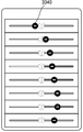
본 발명의 일 실시예에 따른 초음파 장치의 정보 제공 방법은, 이득 값을 설정할 수 있는 적어도 하나의 슬라이드 바를 이득 설정 창에 표시하는 단계를 포함할 수 있다. The information providing method of an ultrasonic apparatus according to an embodiment of the present invention may include displaying at least one slide bar capable of setting a gain value on a gain setting window.
본 발명의 일 실시예에 따른 초음파 장치의 정보 제공 방법은, 초음파 영상의 깊이 방향을 따라 적어도 하나의 슬라이드 바를 배열하여 표시하는 단계를 포함할 수 있다. The information providing method of the ultrasonic apparatus according to an embodiment of the present invention may include arranging and displaying at least one slide bar along the depth direction of the ultrasonic image.
본 발명의 일 실시예에 따른 초음파 장치의 정보 제공 방법은, 적어도 하나의 슬라이드 바에 대한 사용자의 터치 입력을 감지하는 단계; 및 터치 입력의 위치에 대응하는 이득 값을 추출하는 단계를 포함할 수 있다. According to another aspect of the present invention, there is provided an information providing method for an ultrasonic apparatus, comprising: sensing touch inputs of a user to at least one slide bar; And extracting a gain value corresponding to the position of the touch input.
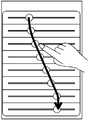
본 발명의 일 실시예에 따른 초음파 장치의 정보 제공 방법은, 이득 설정 창 안에서 적어도 하나의 슬라이드 바에 수직하는 방향으로 드래그하는 사용자의 드래그 입력을 감지하는 단계; 및 드래그 입력의 위치에 기초하여, 초음파 영상의 깊이 값 각각에 대응하는 이득 값을 추출하는 단계를 포함할 수 있다. According to another aspect of the present invention, there is provided an information providing method of an ultrasonic apparatus, comprising: detecting a drag input of a user dragging in a direction perpendicular to at least one slide bar in a gain setting window; And extracting a gain value corresponding to each depth value of the ultrasound image based on the position of the drag input.
본 발명의 일 실시예에 따른 초음파 장치의 정보 제공 방법은, 드래그 입력의 위치에 기초하여 추출된 이득 값에 따라, 적어도 하나의 슬라이드 바 상의 조절 버튼을 이동하여 표시하는 단계를 더 포함할 수 있다. The method of providing information of an ultrasonic apparatus according to an embodiment of the present invention may further include moving and displaying an adjustment button on at least one slide bar according to a gain value extracted based on a position of a drag input .
본 발명의 일 실시예에 따른 초음파 장치의 정보 제공 방법은, 이득 설정 창을 통해 설정된 이득 값에 대응하는 이득 라인을 획득하는 단계; 및 획득된 이득 라인을 제 2 영역에 표시하는 단계를 더 포함할 수 있다. According to another aspect of the present invention, there is provided an information providing method of an ultrasonic apparatus, comprising: obtaining a gain line corresponding to a gain value set through a gain setting window; And displaying the obtained gain line in the second area.
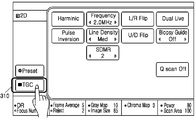
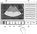
본 발명의 일 실시예에 따른 초음파 장치의 정보 제공 방법은, 적어도 하나의 기 설정된 이득 값의 목록을 화면의 제 3 영역에 표시하는 단계를 더 포함할 수 있다. The method of providing information of an ultrasonic apparatus according to an embodiment of the present invention may further include displaying a list of at least one predetermined gain value in a third area of the screen.
본 발명의 일 실시예에 따른 초음파 장치의 정보 제공 방법은, 목록에서 하나의 기 설정된 이득 값을 선택 받는 단계; 선택된 기 설정된 이득 값을 이득 설정 창에 표시하는 단계; 및 선택된 기 설정된 이득 값이 적용된 초음파 영상을 제 2 영역에 표시하는 단계를 더 포함할 수 있다. According to an embodiment of the present invention, there is provided an information providing method of an ultrasonic apparatus, comprising: receiving a predetermined gain value from a list; Displaying a selected predetermined gain value in a gain setting window; And displaying the ultrasound image to which the selected predetermined gain value is applied in the second area.
본 발명의 일 실시예에 따른 초음파 장치의 정보 제공 방법은, 선택된 기 설정된 이득 값에 대한 사용자의 추가 설정을 입력 받는 단계를 더 포함할 수 있다. The method of providing information of an ultrasonic apparatus according to an embodiment of the present invention may further include inputting a user's additional setting for a selected predetermined gain value.
본 발명의 일 실시예에 따른 초음파 장치의 정보 제공 방법은, 사용자 입력에 기초하여, 이득 설정 창을 통해 설정된 이득 값을 저장하는 단계; 및 저장된 이득 값의 이미지를 제 3 영역에 표시하는 단계를 더 포함할 수 있다. According to an embodiment of the present invention, there is provided an information providing method of an ultrasonic apparatus, comprising: storing a gain value set through a gain setting window based on a user input; And displaying an image of the stored gain value in a third area.
본 발명의 일 실시예에 따른 초음파 장치의 정보 제공 방법은, 바디마커, 애플리케이션 정보, 및 프로브 설정 정보 중 적어도 하나를 기 설정된 이득 값의 목록에 더 포함하여 표시하는 단계를 포함할 수 있다. The method may further include displaying at least one of the body marker, the application information, and the probe setting information in a list of predetermined gain values.
본 발명의 일 실시예에 따른 초음파 장치의 정보 제공 방법은, 이득 설정 창을 통해 설정된 이득 값을 외부 저장 매체에 저장하는 단계를 더 포함할 수 있다. The method of providing information of an ultrasonic apparatus according to an embodiment of the present invention may further include storing a gain value set through a gain setting window in an external storage medium.
본 발명의 일 실시예에 따른 초음파 장치의 정보 제공 방법은, 이득 설정 창을 통해 설정된 이득 값을 초음파 영상과 관련된 적어도 하나의 파라미터 값과 연결하여 저장하는 단계를 더 포함할 수 있다. The method of providing information of an ultrasonic apparatus according to an embodiment of the present invention may further include storing a gain value set through a gain setting window in association with at least one parameter value related to an ultrasound image.
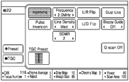
본 발명의 일 실시예에 따른 파라미터는, 주파수(frequency), 다이나믹 레인지(dynamic range), 프레임 평균(Frame average), 리젝트 레벨(reject level), 그레이 맵(gray map), 공간 컴파운드(spatial compound), DMR+, 하모닉(Harmonic), 스캔 영역(Scan Area), 에지 강화(edge enhance), 속도(speed), 파워(Power), 선 밀도(Line Density), FSI, 초점 수(Focus Number), 및 깊이 값(depth) 중 적어도 하나를 포함할 수 있다.The parameters according to an embodiment of the present invention may include at least one of a frequency, a dynamic range, a frame average, a reject level, a gray map, a spatial compound ), DMR +, Harmonic, Scan Area, Edge Enhancement, Speed, Power, Line Density, FSI, Focus Number, And a depth value (depth).
본 발명의 일 실시예에 따른 초음파 장치의 정보 제공 방법은, 이득 설정 창을 통해 설정된 이득 값을 유무선 통신을 통해 외부 장치로 전송하는 단계를 더 포함할 수 있다. The method of providing information of the ultrasonic apparatus according to an embodiment of the present invention may further include transmitting a gain value set through the gain setting window to an external device through wired / wireless communication.
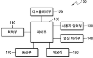
본 발명의 일 실시예에 따른 초음파 장치(100)는 대상체에 대한 초음파 영상 데이터를 획득하는 획득부; 획득된 초음파 영상 데이터의 이득 값을 설정하기 위한 이득 설정 창을 화면의 제 1 영역에 표시하고, 대상체에 대한 초음파 영상을 화면의 제 2 영역에 표시하는 디스플레이부; 이득 설정 창을 통해 사용자로부터 이득 값을 설정 받는 사용자 입력부; 이득 설정 창을 통해 설정된 이득 값을 초음파 영상 데이터에 적용하여 제 2 영역에 표시되는 초음파 영상을 생성하는 영상 처리부; 및 획득부, 디스플레이부, 사용자 입력부 및 영상 처리부를 제어하는 제어부를 포함할 수 있다. The
본 발명의 일 실시예에 따른 초음파 장치(100)의 디스플레이부는, 이득 값을 각각 설정할 수 있는 적어도 하나의 슬라이드 바를 이득 설정 창에 표시할 수 있다. The display unit of the
본 발명의 일 실시예에 따른 초음파 장치(100)의 제어부는, 이득 설정 창을 통해 설정된 이득 값에 대응하는 이득 라인을 획득하고, 획득된 이득 라인이 제 2 영역에 표시되도록 디스플레이부를 제어할 수 있다. The control unit of the
본 발명의 일 실시예에 따른 초음파 장치(100)의 디스플레이부는, 적어도 하나의 기 설정된 이득 값의 목록을 화면의 제 3 영역에 표시할 수 있다. The display unit of the
본 발명의 일 실시예에 따른 초음파 장치(100)는, 이득 설정 창을 통해 설정된 이득 값을 저장하는 메모리를 더 포함할 수 있다. The
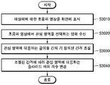
본 발명의 일 실시예에 따른 초음파 장치의 정보 제공 방법은, 기 설정된 이득 값의 목록을 화면에 표시하는 단계; 목록에서 하나의 기 설정된 이득 값을 선택 받는 단계; 및 선택된 기 설정된 이득 값을 대상체에 대한 초음파 영상 데이터에 적용하는 단계를 포함할 수 있다. According to another aspect of the present invention, there is provided an information providing method of an ultrasonic apparatus, comprising: displaying a list of predetermined gain values on a screen; Selecting one predetermined gain value from the list; And applying the selected predetermined gain value to the ultrasound image data for the target object.
본 발명의 일 실시예에 따른 초음파 장치의 정보 제공 방법은, 대상체에 대한 초음파 영상 데이터를 획득하는 단계; 획득된 초음파 영상 데이터의 이득 값을 설정하기 위한 이득 설정 창을 화면의 제 1 영역에 표시하는 단계; 획득된 초음파 영상 데이터에 기초하여, 대상체에 대한 초음파 영상을 화면의 제 2 영역에 표시하는 단계; 및 기 설정된 이득 값의 목록을 화면의 제 3 영역에 표시하는 단계를 포함할 수 있다. According to an embodiment of the present invention, there is provided an information providing method of an ultrasound system, comprising: obtaining ultrasound image data for a target object; Displaying a gain setting window for setting a gain value of the obtained ultrasound image data in a first area of the screen; Displaying an ultrasound image of a target object on a second area of the screen based on the obtained ultrasound image data; And displaying a list of predetermined gain values in a third area of the screen.
본 발명의 일 실시예에 따른 초음파 장치의 정보 제공 방법은, 기 설정된 이득 값의 목록을 외부 저장 매체로부터 획득하는 단계를 포함할 수 있다. The information providing method of the ultrasonic apparatus according to an embodiment of the present invention may include acquiring a list of predetermined gain values from an external storage medium.
본 발명의 일 실시예에 따른 초음파 장치의 정보 제공 방법은, 기 설정된 이득 값의 목록에서 하나의 기 설정된 이득 값을 선택 받는 단계; 선택된 기 설정된 이득 값을 이득 설정 창에 표시하는 단계; 및 선택된 기 설정된 이득 값이 적용된 초음파 영상을 제 2 영역에 표시하는 단계를 더 포함할 수 있다.본 발명의 일 실시예에 따른 초음파 장치의 정보 제공 방법은, 이득 설정 창에 표시된 기 설정된 이득 값에 대한 사용자의 추가 설정을 입력 받는 단계를 더 포함할 수 있다. According to an embodiment of the present invention, there is provided an information providing method of an ultrasonic apparatus, comprising: receiving a predetermined gain value from a list of predetermined gain values; Displaying a selected predetermined gain value in a gain setting window; And displaying the ultrasound image to which the selected pre-set gain value is applied in the second area. According to another aspect of the present invention, there is provided an information providing method of an ultrasound system, And further receiving a user's additional setting for the user.
본 발명의 일 실시예에 따른 초음파 장치의 정보 제공 방법은, 추가 설정된 이득 값을 저장하는 단계를 더 포함할 수 있다. The method of providing information of an ultrasonic apparatus according to an embodiment of the present invention may further include storing a gain value set in advance.
본 발명의 일 실시예에 따른 초음파 장치의 정보 제공 방법은, 추가 설정된 이득 값을 외부 저장 매체에 저장하는 단계를 더 포함할 수 있다. The method of providing information of an ultrasonic apparatus according to an embodiment of the present invention may further include storing a gain value set in the external storage medium.
본 발명의 일 실시예에 따른 초음파 장치의 정보 제공 방법은, 선택된 기 설정된 이득 값에 맵핑된 적어도 하나의 파라미터 값을 표시하는 단계를 더 포함하고, 파라미터 값은 초음파 영상과 관련하여 미리 설정된 값일 수 있다. The method may further include displaying at least one parameter value mapped to a selected predetermined gain value. The parameter value may be a predetermined value related to the ultrasound image have.
본 발명의 일 실시예에 따른 초음파 장치의 정보 제공 방법은, 선택된 기 설정된 이득 값에 맵핑된 적어도 하나의 파라미터 값을 확인하는 단계; 및 확인된 적어도 하나의 파라미터 값을 시스템에 적용하는 단계를 더 포함할 수 있다. According to an embodiment of the present invention, there is provided an information providing method of an ultrasonic apparatus, comprising: confirming at least one parameter value mapped to a selected predetermined gain value; And applying the identified at least one parameter value to the system.
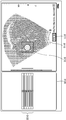
본 발명의 일 실시예에 따른 초음파 장치의 정보 제공 방법은, 그레이 스케일을 결정하기 위한 그레이 맵 목록 및 3차원 볼륨 데이터에서 소정 영역을 선택하기 위한 커브 목록 중 적어도 하나를 화면의 제 4 영역에 표시하는 단계를 더 포함할 수 있다. According to an embodiment of the present invention, at least one of a gray map list for determining a gray scale and a curve list for selecting a predetermined area from three-dimensional volume data is displayed on a fourth area of the screen The method comprising the steps of:
본 발명의 일 실시예에 따른 초음파 장치의 정보 제공 방법은, 초음파 장치에 연결된 프로브의 식별 정보를 확인하는 단계; 프로브의 식별 정보에 대응하는 기 설정된 이득 값을 추출하는 단계; 및 기 설정된 이득 값을 초음파 영상 데이터에 적용하는 단계를 포함할 수 있다. According to an embodiment of the present invention, there is provided an information providing method of an ultrasonic apparatus, comprising: identifying identification information of a probe connected to an ultrasonic apparatus; Extracting a predetermined gain value corresponding to the identification information of the probe; And applying the predetermined gain value to the ultrasound image data.
본 발명의 일 실시예에 따른 초음파 장치의 정보 제공 방법은, 초음파 장치에 연결된 적어도 하나의 프로브의 식별 정보를 포함하는 프로브 목록을 표시하는 단계; 프로브 목록에서 하나의 프로브의 식별 정보를 선택 받는 단계; 및 선택된 프로브의 식별 정보에 대응하는 기 설정된 이득 값을 초음파 영상 데이터에 적용하는 단계를 더 포함할 수 있다.According to an embodiment of the present invention, there is provided an information providing method of an ultrasonic apparatus, comprising: displaying a probe list including identification information of at least one probe connected to the ultrasonic apparatus; Receiving identification information of one probe from the probe list; And applying the predetermined gain value corresponding to the identification information of the selected probe to the ultrasound image data.
본 발명의 일 실시예에 따른 초음파 장치의 정보 제공 방법은, 프로브의 식별 정보에 대응하는 복수의 기 설정된 이득 값을 추출하는 단계; 복수의 기 설정된 이득 값을 포함하는 기 설정된 이득 값의 목록을 표시하는 단계; 및 기 설정된 이득 값의 목록에서 하나의 기 설정된 이득 값을 선택 받는 단계를 포함할 수 있다. According to an embodiment of the present invention, there is provided an information providing method of an ultrasonic apparatus, comprising: extracting a plurality of predetermined gain values corresponding to identification information of a probe; Displaying a list of predetermined gain values including a plurality of predetermined gain values; And receiving a predetermined gain value from the list of predetermined gain values.
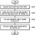
본 발명의 일 실시예에 따른 초음파 장치의 정보 제공 방법은, 진단과를 나타내는 애플리케이션 정보를 입력 받는 단계; 및 프로브의 식별 정보 및 입력된 애플리케이션 정보에 대응하는 기 설정된 이득 값을 추출하는 단계를 포함할 수 있다. An information providing method of an ultrasonic apparatus according to an embodiment of the present invention includes: receiving application information indicating a diagnosis; And extracting identification information of the probe and a predetermined gain value corresponding to the inputted application information.
본 발명의 일 실시예에 따른 초음파 장치의 정보 제공 방법은, 추출된 기 설정된 이득 값을 화면의 소정 영역에 표시하는 단계를 더 포함할 수 있다. The method of providing information of the ultrasonic apparatus according to an embodiment of the present invention may further include displaying the extracted predetermined gain value in a predetermined area of the screen.
본 발명의 일 실시예에 따른 초음파 장치의 정보 제공 방법은, 표시된 기 설정된 이득 값에 대한 사용자의 추가 설정을 입력 받는 단계를 더 포함할 수 있다. The method of providing information of an ultrasonic apparatus according to an embodiment of the present invention may further include receiving a user's additional setting for a predetermined gain value displayed.
본 발명의 일 실시예에 따른 초음파 장치의 정보 제공 방법은, 초음파 영상 데이터의 이득 값을 설정하기 위한 이득 설정 창을 화면에 표시하는 단계; 이득 설정 창을 통해 사용자로부터 이득 값을 설정 받는 단계; 및 설정된 이득 값과 상기 사용자에 의해 선택된 프로브의 식별 정보를 맵핑하여 저장하는 단계를 더 포함할 수 있다. According to another aspect of the present invention, there is provided an information providing method of an ultrasound system, comprising: displaying a gain setting window for setting a gain value of ultrasound image data on a screen; Receiving a gain value from a user through a gain setting window; And mapping and storing the set gain value and the identification information of the probe selected by the user.
본 발명의 일 실시예에 따른 초음파 장치의 정보 제공 방법은, 초음파 영상 데이터의 이득 값을 설정하기 위한 이득 설정 창을 화면에 표시하는 단계; 이득 설정 창을 통해 사용자로부터 이득 값을 설정 받는 단계; 및 설정된 이득 값, 사용자에 의해 선택된 프로브의 식별 정보 및 진단과를 나타내는 애플리케이션 정보를 맵핑하여 저장하는 단계를 더 포함할 수 있다. According to another aspect of the present invention, there is provided an information providing method of an ultrasound system, comprising: displaying a gain setting window for setting a gain value of ultrasound image data on a screen; Receiving a gain value from a user through a gain setting window; And a step of mapping and storing the set gain value, the identification information of the probe selected by the user, and the application information indicating the diagnosis.
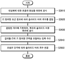
본 발명의 일 실시예에 따른 초음파 장치의 정보 제공 방법은, 대상체에 대한 초음파 영상을 화면에 표시하는 단계; 기 정의된 조건 정보에 따라 초음파 영상의 TGC(Time Gain Compensation) 값을 조절하기 위한 슬라이드 바의 개수를 결정하는 단계; 및 결정된 개수에 기초하여, 초음파 영상의 복수의 깊이에 대응하는 복수의 슬라이드 바를 화면에 표시하는 단계를 포함할 수 있다. According to an embodiment of the present invention, there is provided an information providing method of an ultrasound system, comprising: displaying an ultrasound image of a target object on a screen; Determining a number of slide bars for adjusting a TGC (Time Gain Compensation) value of the ultrasound image according to predefined condition information; And displaying the plurality of slide bars corresponding to the plurality of depths of the ultrasound image on the screen based on the determined number.
본 발명의 일 실시예에 따른 슬라이드 바의 개수를 결정하는 단계는, 초음파 영상의 전체 깊이 및 복수의 깊이 간의 기 정의된 간격에 기초하여, 슬라이드 바의 개수를 결정하는 단계를 포함할 수 있다. The step of determining the number of slide bars according to an embodiment of the present invention may include determining the number of slide bars based on the predefined interval between the total depth of the ultrasound image and the plurality of depths.
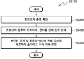
본 발명의 일 실시예에 따른 슬라이드 바의 개수를 결정하는 단계는, 프로브의 종류에 기초하여, 초음파 영상의 복수의 깊이 간의 간격을 선택하는 단계; 및 선택된 간격 및 초음파 영상의 전체 깊이에 기초하여 슬라이드 바의 개수를 결정하는 단계를 포함할 수 있다. The step of determining the number of slide bars according to an exemplary embodiment of the present invention includes: selecting an interval between a plurality of depths of an ultrasound image based on a kind of a probe; And determining the number of slide bars based on the selected spacing and the total depth of the ultrasound image.
본 발명의 일 실시예에 따른 프로브는, 컨벡스 프로브(Convex probe) 및 선형 프로브(Linear probe) 중 적어도 하나를 포함할 수 있다. The probe according to an embodiment of the present invention may include at least one of a convex probe and a linear probe.
본 발명의 일 실시예에 따른 초음파 장치의 정보 제공 방법은, 복수의 깊이 간의 기 정의된 간격을 조절하는 입력을 수신하는 단계; 및 조절된 간격에 따라 결정된 슬라이드 바의 개수를 변경하는 단계를 더 포함할 수 있다. According to an embodiment of the present invention, there is provided an information providing method of an ultrasonic apparatus, comprising: receiving an input for adjusting a predefined interval between a plurality of depths; And changing the number of slide bars determined according to the adjusted interval.
본 발명의 일 실시예에 따른 기 정의된 간격을 조절하는 입력을 수신하는 단계는, 복수의 깊이 중 제 1 구간에 대응하는 제 1 간격을 제 1 값으로 조절하고, 복수의 깊이 중 제 2 구간에 대응하는 제 2 간격을 제 2 값으로 조절하는 입력을 수신하는 단계를 포함할 수 있다. The step of receiving the predefined interval adjusting input according to an embodiment of the present invention includes adjusting a first interval corresponding to a first interval of the plurality of depths to a first value, And receiving an input that adjusts a second interval corresponding to a second value to a second value.
본 발명의 일 실시예에 따른 기 정의된 간격을 조절하는 입력을 수신하는 단계는, 초음파 영상에서 관심 영역을 선택하는 입력을 수신하는 단계; 및 관심 영역에 대응하는 깊이들 간의 기 정의된 간격을 조절하는 단계를 포함할 수 있다. The step of receiving the predefined interval adjusting input according to an embodiment of the present invention includes receiving an input for selecting an area of interest in an ultrasound image; And adjusting the predefined spacing between the depths corresponding to the region of interest.
본 발명의 일 실시예에 따른 슬라이드 바의 개수를 결정하는 단계는, 대상체의 종류에 기초하여, 슬라이드 바의 개수를 결정하는 단계를 포함할 수 있다. The step of determining the number of slide bars according to an embodiment of the present invention may include a step of determining the number of slide bars based on the type of the object.
본 발명의 일 실시예에 따른 결정된 슬라이드 바의 개수를 변경하는 단계는, 변경된 개수에 기초하여, 적어도 하나의 슬라이드 바를 화면에 더 표시하는 단계를 포함할 수 있다.The step of changing the number of determined slide bars according to an embodiment of the present invention may include the step of displaying at least one slide bar on the screen based on the changed number.
본 발명의 일 실시예에 따른 결정된 슬라이드 바의 개수를 변경하는 단계는, 변경된 개수에 따라, 초음파 영상의 복수의 깊이에 대응하는 슬라이드 바들을 새로운 창에 표시하는 단계; 및 새로운 창에 표시된 슬라이드 바들 상의 조절 버튼을 이용하여 초음파 영상의 TGC 값을 조절하는 입력을 수신하는 단계를 포함할 수 있다.The step of changing the number of determined slide bars according to an embodiment of the present invention includes the steps of displaying slide bars corresponding to a plurality of depths of the ultrasound image in a new window according to the changed number; And receiving an input for adjusting a TGC value of the ultrasound image using an adjustment button on a slide bar displayed in a new window.
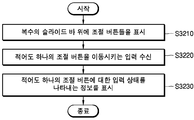
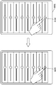
본 발명의 일 실시예에 따른 복수의 슬라이드 바를 표시하는 단계는, 복수의 슬라이드 바 위에 조절 버튼들을 표시하는 단계; 조절 버튼들 중에서 적어도 하나의 조절 버튼을 이동시키는 입력을 수신하는 단계; 및 적어도 하나의 조절 버튼에 대한 입력 상태를 나타내는 정보를 적어도 하나의 조절 버튼 위에 표시하는 단계를 포함할 수 있다. The step of displaying a plurality of slide bars according to an embodiment of the present invention includes: displaying control buttons on a plurality of slide bars; Receiving an input for moving at least one adjustment button among the adjustment buttons; And displaying information indicating an input state of at least one control button on the at least one control button.
본 발명의 일 실시예에 따른 적어도 하나의 조절 버튼을 이동시키는 입력은, 터치 입력, 근접 터치 입력, 및 3차원 모션 입력 중 적어도 하나를 포함할 수 있다. The input for moving the at least one control button according to an embodiment of the present invention may include at least one of a touch input, a proximity touch input, and a three-dimensional motion input.
본 발명의 일 실시예에 따른 복수의 슬라이드 바를 표시하는 단계는, 초음파 영상의 전체 깊이 중에서 일부 깊이를 선택하는 단계; 및 선택된 일부 깊이에 대응하는 슬라이드 바들을 표시하는 단계를 포함할 수 있다.According to an embodiment of the present invention, the step of displaying a plurality of slide bars may include the steps of: selecting a part of the entire depth of the ultrasound image; And displaying slide bars corresponding to some selected depths.
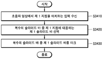
본 발명의 일 실시예에 따른 초음파 장치의 정보 제공 방법은, 표시된 초음파 영상에서 제 1 지점을 터치하는 입력을 수신하는 단계; 복수의 슬라이드 바 중 제 1 지점에 대응하는 제 1 슬라이드 바를 선택하는 단계; 및 복수의 슬라이드 바 중 제 1 슬라이드 바를 마크하는 단계를 더 포함할 수 있다. According to another aspect of the present invention, there is provided an information providing method for an ultrasound system, comprising: receiving an input for touching a first point in a displayed ultrasound image; Selecting a first slide bar corresponding to a first point of the plurality of slide bars; And marking the first slide bar of the plurality of slide bars.
본 발명의 일 실시예에 따른 초음파 장치의 정보 제공 방법은, 복수의 슬라이드 바 중 제 1 슬라이드 바에 대한 사용자의 터치 입력을 수신하는 단계; 터치 입력의 위치에 대응하는 TGC 값을 추출하는 단계; 및 추출된 TGC 값을 초음파 영상 중에서 제 1 슬라이드 바에 대응하는 영역에 적용하는 단계를 더 포함할 수 있다. According to an embodiment of the present invention, there is provided an information providing method of an ultrasonic apparatus, comprising: receiving a touch input of a user to a first slide bar among a plurality of slide bars; Extracting a TGC value corresponding to a position of the touch input; And applying the extracted TGC value to an area corresponding to the first slide bar in the ultrasound image.
본 발명의 일 실시예에 따른 초음파 장치는, 대상체에 대한 초음파 영상을 표시하는 디스플레이부; 및 초음파 영상의 TGC(Time Gain Compensation) 값을 조절하기 위한 슬라이드 바의 개수를 기 정의된 조건 정보에 따라 결정하고, 상기 결정된 개수에 기초하여, 초음파 영상의 복수의 깊이에 대응하는 복수의 슬라이드 바를 표시하도록 디스플레이부를 제어하는 제어부를 포함할 수 있다. According to an embodiment of the present invention, there is provided an ultrasound system including a display unit for displaying an ultrasound image of a target object; And determining a number of slide bars for adjusting a TGC (Time Gain Compensation) value of the ultrasound image according to predefined condition information, and based on the determined number, a plurality of slide bars corresponding to a plurality of depths of the ultrasound image And a control unit for controlling the display unit to display the display unit.
본 발명의 일 실시예에 따른 초음파 장치의 제어부는, 초음파 영상의 전체 깊이 및 복수의 깊이 간의 기 정의된 간격에 기초하여, 슬라이드 바의 개수를 결정할 수 있다. The controller of the ultrasonic apparatus according to an embodiment of the present invention can determine the number of slide bars based on the predefined interval between the total depth of the ultrasonic image and the plurality of depths.
본 발명의 일 실시예에 따른 초음파 장치는, 복수의 깊이 간의 기 정의된 간격을 조절하는 입력을 수신하는 사용자 입력부를 더 포함하고, 제어부는, 조절된 간격에 따라 상기 결정된 슬라이드 바의 개수를 변경할 수 있다.The ultrasonic apparatus according to an embodiment of the present invention may further include a user input unit for receiving an input for adjusting a predefined interval between a plurality of depths and the controller may change the determined number of slide bars according to the adjusted interval .
본 발명의 일 실시예에 따른 초음파 장치는, 복수의 슬라이드 바 위에 표시된 조절 버튼들 중에서 적어도 하나의 조절 버튼을 이동시키는 입력을 수신하는 사용자 입력부를 더 포함하고, 디스플레이부는, 적어도 하나의 조절 버튼에 대한 입력 상태를 나타내는 정보를 적어도 하나의 조절 버튼 위에 표시할 수 있다.The ultrasonic apparatus according to an embodiment of the present invention may further include a user input unit for receiving an input for moving at least one adjustment button among the adjustment buttons displayed on the plurality of slide bars, Information indicative of the input state can be displayed on at least one control button.
본 발명의 일 실시예에 의하면, 초음파 장치는, 초음파 영상의 전체 깊이가 깊을수록, 초음파 영상의 TGC 값을 조절하기 위한 슬라이드 바의 개수를 증가시켜, 사용자가 디지털 TGC 값(초음파 영상의 밝기 값)을 세밀하게 조절하도록 할 수 있다.According to an embodiment of the present invention, the ultrasound device increases the number of slide bars for adjusting the TGC value of the ultrasound image as the entire depth of the ultrasound image is deeper, and when the user changes the digital TGC value Can be finely adjusted.
도 1a, 1b, 및 1c는 본 발명의 일 실시예에 따른 초음파 장치를 설명하기 위한 도면이다.
도 2는 본 발명의 일 실시예와 관련된 초음파 장치의 정보 제공 방법을 설명하기 위한 순서도이다.
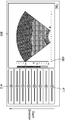
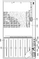
도 3은 본 발명의 일 실시예와 관련된 초음파 장치의 TGC(Time Gain Compensation) 설정 시작 화면의 일례를 나타내는 도면이다.
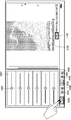
도 4는 본 발명의 일 실시예에 관련된 이득 값을 설정하기 위한 이득 설정 창을 나타내는 도면이다.
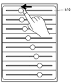
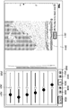
도 5a, 5b 및 5c는 본 발명의 일 실시예에 따른 사용자로부터 이득 값을 설정 받는 화면을 나타내는 도면이다.
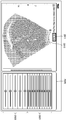
도 6은 본 발명의 일 실시예와 관련된 이득 값에 대응하는 이득 라인을 나타내는 도면이다.
도 7은 본 발명의 일 실시예와 관련된 기 설정된 이득 값의 목록을 나타내는 도면이다.
도 8은 본 발명의 일 실시예와 관련된 초음파 장치의 이득 값 저장 방법을 설명하기 위한 순서도이다.
도 9a, 9b 및 9c는 본 발명의 일 실시예와 관련된 이득 값을 저장하기 위한 GUI의 일례를 나타내는 도면이다.
도 10은 본 발명의 일 실시예와 관련된 LGC(Lateral Gain Compensation) 값을 설정하기 위한 이득 설정 창을 나타내는 도면이다.
도 11은 본 발명의 일 실시예와 관련된 초음파 장치의 정보 제공 방법을 설명하기 위한 순서도이다.
도 12는 본 발명의 또 다른 실시예와 관련된 초음파 장치의 정보 제공 방법을 설명하기 위한 순서도이다.
도 13은 본 발명의 일 실시예에 따른 초음파 영상과 관련된 설정 파라미터들의 일례를 나타내는 도면이다.
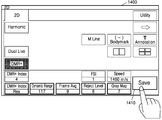
도 14a 및 14b는 본 발명의 일 실시예에 따른 초음파 영상과 관련된 파라미터 값을 설정하는 GUI의 일례를 나타내는 도면이다.
도 15a, 15b, 15c 및 15d는 미리 설정된 적어도 하나의 파라미터 값을 저장하는 GUI의 일례를 나타내는 도면이다.
도 16은 본 발명의 일 실시예에 따른 프로브의 식별 정보에 기초한 초음파 장치의 정보 제공 방법을 설명하기 위한 순서도이다.
도 17a, 17b, 18a 및 18b는 사용자에 의해 선택된 사용자 프리셋에 대응하는 파라미터 값 및 이득 값을 나타내는 도면이다.
도 19a 및 19b는 본 발명의 일 실시예에 따른 기 설정된 그레이 맵 목록을 설명하기 위한 도면이다.
도 20a 및 20b는 본 발명의 일 실시예에 따른 기 설정된 커브 목록을 나타내는 도면이다.
도 21은, 본 발명의 일 실시예에 따르는, 초음파 장치의 정보 제공 방법을 설명하기 위한 순서도이다.
도 22는, 본 발명의 일 실시예에 따르는, 초음파 영상의 전체 깊이 및 기 정의된 간격에 기초하여 슬라이드 바의 개수를 결정하는 방법을 설명하기 위한 순서도이다.
도 23a 및 23b는, 초음파 장치에서 초음파 영상의 전체 깊이 및 기 정의된 간격을 고려하여, 복수의 슬라이드 바를 제공하는 일례를 나타내는 도면이다.
도 24는, 본 발명의 일 실시예에 따르는, 프로브의 종류에 기초하여 슬라이드 바의 개수를 결정하는 방법을 설명하기 위한 순서도이다.
도 25a 및 25b는, 초음파 장치에서 프로브의 종류를 고려하여 복수의 슬라이드 바를 제공하는 일례를 나타내는 도면이다.
도 26은, 본 발명의 일 실시예에 따르는, 초음파 장치에서 사용자 입력에 기초하여 슬라이드 바의 개수를 변경하는 방법을 설명하기 위한 순서도이다.
도 27a 내지 27c는, 사용자 입력에 기초하여 슬라이드 바의 개수를 변경하는 일례를 나타내는 도면이다.
도 28a 내지 28d는, 초음파 장치에서 새로운 창에 복수의 슬라이드 바를 표시하는 일례를 나타내는 도면이다.
도 29는, 초음파 장치에서 깊이 구간별로 슬라이드 바의 간격을 다르게 표시하는 일례를 나타내는 도면이다.
도 30은, 본 발명의 일 실시예에 따르는, 관심 영역에 대응하는 슬라이드 바의 개수를 변경하는 방법을 설명하기 위한 순서도이다.
도 31a는 관심 영역에 대응하는 슬라이드 바의 개수를 변경하는 일례를 나타내는 도면이고, 도 31b는 관심 영역에 대응하는 슬라이드 바를 표시하는 일례를 나타내는 도면이고, 도 31c는 병변을 포함하는 일정 영역에 대응하는 슬라이드 바의 개수를 변경하는 일례를 나타내는 도면이다.
도 32는, 본 발명의 일 실시예에 따르는, 초음파 장치가 조절 버튼 위에 해당 조절 버튼에 대한 입력 상태를 나타내는 정보를 표시하는 방법을 설명하기 위한 순서도이다.
도 33a 내지 33c는 초음파 장치가 조절 버튼 위에 해당 조절 버튼에 대한 입력 상태를 나타내는 정보를 표시하는 일례를 나타내는 도면이다.
도 34는, 본 발명의 일 실시예에 따르는, 초음파 영상에서 사용자에 의해 선택된 특정 지점에 대응하는 슬라이드 바를 마크하는 방법을 설명하기 위한 순서도이다.
도 35a 및 35b는, 초음파 영상에서 사용자에 의해 선택된 특정 지점에 대응하는 슬라이드 바를 마크하는 일례를 나타내는 도면이다.1A, 1B and 1C are views for explaining an ultrasonic device according to an embodiment of the present invention.
2 is a flowchart illustrating an information providing method of an ultrasonic apparatus according to an embodiment of the present invention.
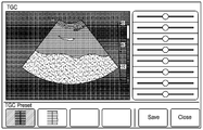
3 is a view showing an example of a TGC (Time Gain Compensation) setting start screen of the ultrasonic apparatus according to an embodiment of the present invention.
4 is a diagram illustrating a gain setting window for setting a gain value according to an embodiment of the present invention.
5A, 5B, and 5C are views illustrating a screen for setting a gain value from a user according to an exemplary embodiment of the present invention.
6 is a diagram illustrating a gain line corresponding to a gain value associated with an embodiment of the present invention.
7 is a diagram illustrating a list of predetermined gain values associated with an embodiment of the present invention.
8 is a flowchart illustrating a method of storing a gain value of an ultrasonic apparatus according to an embodiment of the present invention.
9A, 9B and 9C are diagrams illustrating an example of a GUI for storing gain values associated with an embodiment of the present invention.
10 is a diagram illustrating a gain setting window for setting a value of LGC (Lateral Gain Compensation) according to an embodiment of the present invention.
11 is a flowchart for explaining an information providing method of an ultrasonic apparatus according to an embodiment of the present invention.
12 is a flowchart illustrating an information providing method of an ultrasonic apparatus according to another embodiment of the present invention.
13 is a diagram illustrating an example of configuration parameters related to an ultrasound image according to an embodiment of the present invention.
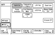
14A and 14B are views showing an example of a GUI for setting a parameter value related to an ultrasound image according to an embodiment of the present invention.
15A, 15B, 15C, and 15D are views showing an example of a GUI storing at least one parameter value set in advance.
16 is a flowchart for explaining an information providing method of an ultrasound system based on identification information of probes according to an embodiment of the present invention.
17A, 17B, 18A and 18B are diagrams showing parameter values and gain values corresponding to user presets selected by the user.
19A and 19B are views for explaining a predetermined gray map list according to an embodiment of the present invention.
20A and 20B are diagrams illustrating a predetermined curve list according to an embodiment of the present invention.
21 is a flowchart for explaining an information providing method of an ultrasonic apparatus according to an embodiment of the present invention.
22 is a flowchart for explaining a method of determining the number of slide bars based on the total depth of the ultrasound image and the predefined interval according to an embodiment of the present invention.
23A and 23B are views showing an example of providing a plurality of slide bars in consideration of the total depth of the ultrasound image and the predefined interval in the ultrasonic apparatus.
Fig. 24 is a flowchart for explaining a method of determining the number of slide bars based on the kind of probe according to an embodiment of the present invention. Fig.
25A and 25B are views showing an example of providing a plurality of slide bars in consideration of the kind of probes in the ultrasonic apparatus.
26 is a flowchart for explaining a method of changing the number of slide bars based on user input in an ultrasonic apparatus according to an embodiment of the present invention.
27A to 27C are diagrams showing an example of changing the number of slide bars based on user input.
28A to 28D are views showing an example of displaying a plurality of slide bars in a new window in the ultrasonic apparatus.
29 is a view showing an example in which the interval of the slide bars is displayed differently for each depth section in the ultrasonic apparatus.
30 is a flowchart for explaining a method for changing the number of slide bars corresponding to a region of interest, according to an embodiment of the present invention.
31A is a diagram showing an example of changing the number of slide bars corresponding to a region of interest, FIG. 31B is a view showing an example of displaying a slide bar corresponding to a region of interest, and FIG. 31C is a diagram And the number of slide bars is changed.
32 is a flowchart illustrating a method of displaying information indicating an input state of a corresponding control button on an adjustment button according to an embodiment of the present invention.
33A to 33C are views showing an example in which the ultrasonic apparatus displays information indicating an input state of the corresponding control button on the control button.
34 is a flowchart for explaining a method of marking a slide bar corresponding to a specific point selected by a user in an ultrasound image, according to an embodiment of the present invention.
35A and 35B are views showing an example of marking a slide bar corresponding to a specific point selected by a user in an ultrasound image.
본 발명에서 사용되는 용어는 본 발명에서의 기능을 고려하면서 가능한 현재 널리 사용되는 일반적인 용어들을 선택하였으나, 이는 당 분야에 종사하는 기술자의 의도 또는 판례, 새로운 기술의 출현 등에 따라 달라질 수 있다. 또한, 특정한 경우는 출원인이 임의로 선정한 용어도 있으며, 이 경우 해당되는 발명의 설명 부분에서 상세히 그 의미를 기재할 것이다. 따라서 본 발명에서 사용되는 용어는 단순한 용어의 명칭이 아닌, 그 용어가 가지는 의미와 본 발명의 전반에 걸친 내용을 토대로 정의되어야 한다. While the present invention has been described in connection with what is presently considered to be the most practical and preferred embodiment, it is to be understood that the invention is not limited to the disclosed embodiments. Also, in certain cases, there may be a term selected arbitrarily by the applicant, in which case the meaning thereof will be described in detail in the description of the corresponding invention. Therefore, the term used in the present invention should be defined based on the meaning of the term, not on the name of a simple term, but on the entire contents of the present invention.
명세서 전체에서 어떤 부분이 어떤 구성요소를 "포함"한다고 할 때, 이는 특별히 반대되는 기재가 없는 한 다른 구성요소를 제외하는 것이 아니라 다른 구성요소를 더 포함할 수 있음을 의미한다. 또한, 명세서에 기재된 "...부", "모듈" 등의 용어는 적어도 하나의 기능이나 동작을 처리하는 단위를 의미하며, 이는 하드웨어 또는 소프트웨어로 구현되거나 하드웨어와 소프트웨어의 결합으로 구현될 수 있다.When an element is referred to as "including" an element throughout the specification, it is to be understood that the element may include other elements, without departing from the spirit or scope of the present invention. Also, the terms "part," " module, "and the like described in the specification mean units for processing at least one function or operation, which may be implemented in hardware or software or a combination of hardware and software .
명세서 전체에서 "초음파 영상"이란 초음파를 이용하여 획득된 대상체에 대한 영상을 의미한다. 대상체는 신체의 일부를 의미할 수 있다. 예를 들어, 대상체에는 간이나, 심장, 자궁, 뇌, 유방, 복부 등의 장기나, 태아 등이 포함될 수 있는 것이다. The term "ultrasound image " in the entire specification refers to an image of a target object obtained by using ultrasound. An object can mean a part of the body. For example, a subject may include an organs such as liver, heart, uterus, brain, breast, abdomen, or fetus.
초음파 영상은 다양하게 구현될 수 있다. 예를 들어, 초음파 영상은 B 모드(brightness mode) 영상, C 모드(color mode) 영상, D 모드(Doppler mode) 영상 중 적어도 하나일 수 있다. 또한, 본 발명의 일 실시예에 의하면, 초음파 영상은 2차원 영상 또는 3차원 영상일 수도 있다.Ultrasonic images can be implemented in various ways. For example, the ultrasound image may be at least one of a brightness mode image, a color mode image, and a D mode image. According to an embodiment of the present invention, the ultrasound image may be a two-dimensional image or a three-dimensional image.
명세서 전체에서 "사용자"는 의료전문가로서 의사, 간호사, 임상병리사, 의료영상 전문가 등이 될 수 있으나, 이에 한정되지 않는다.Throughout the specification, the term "user" may be, but is not limited to, a medical professional such as a doctor, nurse, clinician,
아래에서는 첨부한 도면을 참고하여 본 발명의 실시예에 대하여 본 발명이 속하는 기술 분야에서 통상의 지식을 가진 자가 용이하게 실시할 수 있도록 상세히 설명한다. 그러나 본 발명은 여러 가지 상이한 형태로 구현될 수 있으며 여기에서 설명하는 실시예에 한정되지 않는다. 그리고 도면에서 본 발명을 명확하게 설명하기 위해서 설명과 관계없는 부분은 생략하였으며, 명세서 전체를 통하여 유사한 부분에 대해서는 유사한 도면 부호를 붙였다.Hereinafter, embodiments of the present invention will be described in detail with reference to the accompanying drawings so that those skilled in the art can easily carry out the present invention. The present invention may, however, be embodied in many different forms and should not be construed as limited to the embodiments set forth herein. In order to clearly illustrate the present invention, parts not related to the description are omitted, and similar parts are denoted by like reference characters throughout the specification.
도 1a, 1b 및 1c는 본 발명의 일 실시예에 따른 초음파 장치를 설명하기 위한 도면이다.1A, 1B and 1C are views for explaining an ultrasonic apparatus according to an embodiment of the present invention.
본 발명의 일 실시예에 따른 초음파 장치(100)는 초음파를 이용하여 대상체로부터 초음파 영상 데이터를 획득하고, 사용자에게 초음파 영상 데이터의 이득 값을 설정할 수 있는 GUI(Graphic User Interface)를 제공해 줄 수 있는 기기를 의미한다. The
본 발명의 일 실시예에 따른 초음파 장치(100)는 다양한 형태로 구현이 가능하다. 예를 들어, 본 명세서에서 기술되는 초음파 장치(100)는 고정식 단말뿐만 아니라 이동식 단말 형태로도 구현될 수 있다. 이동식 단말의 일례로 랩탑 컴퓨터, PDA, 태블릿 PC 등이 있을 수 있다.The
도 1a에 도시된 바와 같이, 본 발명의 일 실시예에 따른 초음파 장치(100)는 획득부(110), 디스플레이부(120), 사용자 입력부(130), 영상 처리부(140), 제어부(150)를 포함할 수 있다. 그러나 도시된 구성요소 모두가 필수구성요소인 것은 아니다. 도시된 구성요소보다 많은 구성요소에 의해 초음파 장치(100)가 구현될 수도 있고, 그보다 적은 구성요소에 의해서도 초음파 장치(100)는 구현될 수 있다.1A, an
이하 상기 구성요소들에 대해 차례로 살펴본다.Hereinafter, the components will be described in order.
획득부(110)는 대상체에 대한 초음파 영상 데이터를 획득할 수 있다. 본 발명의 일 실시예에 따른 초음파 영상 데이터는 대상체에 관한 2차원 초음파 영상 데이터일 수도 있고, 3차원 초음파 영상 데이터일 수도 있다. The
본 발명의 일 실시예에 의하면, 획득부(110)는, 초음파 신호를 송수신하기 위한 프로브(도시하지 않음) 및 초음파 신호의 송신 집속 및 수신 집속을 수행하기 위한 빔포머(도시하지 않음)를 포함할 수 있다.According to an embodiment of the present invention, the
본 발명의 일 실시예에 따른 프로브는 1D(Dimension), 1.5D, 2D(matrix), 및 3D 프로브 중 적어도 하나를 포함할 수 있다. The probe according to an embodiment of the present invention may include at least one of 1D (Dimension), 1.5D, 2D (matrix), and 3D probe.
디스플레이부(120)는, 초음파 장치(100)에서 처리되는 정보를 표시 출력할 수 있다. 예를 들어, 디스플레이부(120)는 대상체에 대한 초음파 영상을 화면에 디스플레이할 수도 있고, 기능 설정과 관련된 UI(User Interface) 또는 GUI(Graphic User Interface)를 표시할 수도 있다. The
디스플레이 패널과 후술할 터치패드가 레이어 구조를 이루어 터치 스크린으로 구성되는 경우, 디스플레이부(120)는 출력 장치 이외에 입력 장치로도 사용될 수 있다. 디스플레이부(120)는 액정 디스플레이(liquid crystal display), 박막 트랜지스터 액정 디스플레이(thin film transistor-liquid crystal display), 유기 발광 다이오드(organic light-emitting diode), 플렉시블 디스플레이(flexible display), 3차원 디스플레이(3D display), 전기영동 디스플레이(electrophoretic display) 중에서 적어도 하나를 포함할 수 있다. 그리고 초음파 장치(100)의 구현 형태에 따라 초음파 장치(100)는 디스플레이부(120)를 2개 이상 포함할 수도 있다.In the case where the display panel and the touch pad to be described later have a layer structure and are configured as a touch screen, the
사용자 입력부(130)는, 사용자가 초음파 장치(100)를 제어하기 위한 데이터를 입력하는 수단을 의미한다. 예를 들어, 사용자 입력부(130)에는 키 패드(key pad), 돔 스위치 (dome switch), 터치 패드(접촉식 정전 용량 방식, 압력식 저항막 방식, 적외선 감지 방식, 표면 초음파 전도 방식, 적분식 장력 측정 방식, 피에조 효과 방식 등), 조그 휠, 조그 스위치 등이 있을 수 있으나 이에 한정되는 것은 아니다. 특히, 전술한 바와 같이, 터치 패드가 디스플레이 패널과 레이어 구조를 이룰 경우, 이를 터치 스크린이라 부를 수 있다.The
터치스크린은 터치(real-touch) 뿐만 아니라 근접 터치(proximity touch)도 검출될 수 있도록 구성될 수 있다. 본 명세서에서 "터치(real-touch)"라 함은 화면에 실제로 포인터(pointer)가 터치된 경우를 말하고, "근접 터치(proximity-touch)"라 함은 포인터(pointer)가 화면에 실제로 터치는 되지 않고, 화면으로부터 소정 거리 떨어져 접근된 경우를 말한다. 본 명세서에서 포인터(pointer)는 디스플레이된 화면의 특정 부분을 터치하거나 근접 터치하기 위한 도구를 말한다. 그 일례로 스타일러스 팬, 손가락 등이 있다.The touch screen can be configured to detect not only a real-touch but also a proximity touch. In this specification, the term "real-touch" refers to a case where a pointer is actually touched on the screen, and "proximity-touch" , But approaches a predetermined distance from the screen. In this specification, a pointer is a tool for touching or touching a specific portion of a displayed screen. For example, there are stylus fans and fingers.
도면에는 도시되지 않았지만, 터치스크린의 터치 또는 근접 터치를 감지하기 위해 터치스크린의 내부 또는 근처에 다양한 센서가 구비될 수 있다. 터치스크린의 터치를 감지하기 위한 센서의 일례로 촉각 센서가 있다. 촉각 센서는 사람이 느끼는 정도로 또는 그 이상으로 특정 물체의 접촉을 감지하는 센서를 말한다. 촉각 센서는 접촉면의 거칠기, 접촉 물체의 단단함, 접촉 지점의 온도 등의 다양한 정보를 감지할 수 있다.Although not shown in the drawings, various sensors may be provided inside or near the touch screen to detect touch or proximity touch of the touch screen. An example of a sensor for sensing the touch of the touch screen is a tactile sensor. A tactile sensor is a sensor that detects the contact of a specific object with a degree or more that a person feels. The tactile sensor can detect various information such as the roughness of the contact surface, the rigidity of the contact object, and the temperature of the contact point.
또한, 터치스크린의 터치를 감지하기 위한 센서의 일례로 근접 센서가 있다. 근접 센서는 소정의 검출면에 접근하는 물체, 혹은 근방에 존재하는 물체의 유무를 전자계의 힘 또는 적외선을 이용하여 기계적 접촉이 없이 검출하는 센서를 말한다. 근접 센서의 예로는 투과형 광전 센서, 직접 반사형 광전 센서, 미러 반사형 광전 센서, 고주파 발진형 근접 센서, 정전용량형 근접 센서, 자기형 근접 센서, 적외선 근접 센서 등이 있다. In addition, a proximity sensor is an example of a sensor for sensing the touch of the touch screen. The proximity sensor refers to a sensor that detects the presence or absence of an object approaching a predetermined detection surface or a nearby object without mechanical contact using the force of an electromagnetic field or infrared rays. Examples of proximity sensors include a transmission type photoelectric sensor, a direct reflection type photoelectric sensor, a mirror reflection type photoelectric sensor, a high frequency oscillation type proximity sensor, a capacitive proximity sensor, a magnetic proximity sensor, and an infrared proximity sensor.
한편, 사용자의 터치 제스처에는 탭, 터치&홀드, 더블 탭, 드래그, 패닝, 플릭, 드래그 앤드 드롭, 스와이프 등이 있을 수 있다. Meanwhile, the user's touch gesture may include a tap, a touch & hold, a double tap, a drag, a panning, a flick, a drag and drop, and a swipe.
영상 처리부(140)는 사용자에 의해 설정된 이득 값을 초음파 영상 데이터에 적용할 수 있다. 즉, 영상 처리부(140)는, 사용자에 의해 설정된 이득 값을 초음파 영상 데이터에 적용하여, 화면에 표시되는 초음파 영상을 생성하거나 변경할 수 있는 것이다. The image processing unit 140 may apply the gain value set by the user to the ultrasound image data. That is, the image processing unit 140 may apply the gain value set by the user to the ultrasound image data to generate or change the ultrasound image displayed on the screen.
제어부(150)는 통상적으로 초음파 장치(100)의 전반적인 동작을 제어한다. 즉, 제어부(150)는, 획득부(110), 디스플레이부(120), 사용자 입력부(130), 영상 처리부(140), 등을 전반적으로 제어할 수 있다. The
한편, 도 1b에 도시된 바와 같이, 본 발명의 일 실시예에 따른 초음파 장치(100)는 획득부(110), 디스플레이부(120), 사용자 입력부(130), 영상 처리부(140)이외에 메모리(160), 통신부(170)를 더 포함할 수도 있다. 1B, the
메모리(160)는, 제어부(150)의 처리 및 제어를 위한 프로그램을 저장할 수도 있고, 입/출력되는 데이터들(예를 들어, 기 설정된 이득 값, 초음파 영상, 피검사자 정보, 프로브 정보, 애플리케이션 정보, 바디마커 등)을 저장할 수도 있다. The
메모리(160)는 플래시 메모리 타입(flash memory type), 하드디스크 타입(hard disk type), 멀티미디어 카드 마이크로 타입(multimedia card micro type), 카드 타입의 메모리(예를 들어 SD 또는 XD 메모리 등), 램(RAM, Random Access Memory) SRAM(Static Random Access Memory), 롬(ROM, Read-Only Memory), EEPROM(Electrically Erasable Programmable Read-Only Memory), PROM(Programmable Read-Only Memory) 자기 메모리, 자기 디스크, 광디스크 중 적어도 하나의 타입의 저장매체를 포함할 수 있다. 또한, 초음파 장치(100)는 인터넷(internet)상에서 메모리(160)의 저장 기능을 수행하는 웹 스토리지(web storage) 또는 클라우드 서버를 운영할 수도 있다.The
본 발명의 일 실시예에 따른 초음파 장치(100)는 메모리(예컨대, 내부 저장 매체 또는 외부 저장 매체)(160)에 이득 설정 창을 통해 설정된 이득 값을 저장할 수 있다. The
통신부(170)는 초음파 장치(100)와 외부 장치간의 통신을 하게 하는 하나 이상의 구성요소를 포함할 수 있다. 예를 들어, 통신부(170)는, 근거리 통신 모듈, 이동 통신 모듈, 무선 인터넷 모듈, 유선 인터넷 모듈 등을 포함할 수 있다.The
근거리 통신 모듈은 근거리 통신을 위한 모듈을 말한다. 근거리 통신 기술로 무선 랜(Wi-Fi), 블루투스(Bluetooth), BLE, UWB(Ultra Wideband), 지그비(ZigBee), NFC(Near Field Communication), WFD(Wi-Fi Direct), 적외선 통신(IrDA, infrared Data Association) 등이 이용될 수 있다.The short-range communication module is a module for short-range communication. (WLAN), Bluetooth, BLE, UWB (Ultra Wideband), ZigBee, NFC (Near Field Communication), WFD (Wi-Fi Direct) infrared Data Association) may be used.
이동 통신 모듈은, 이동 통신망 상에서 기지국, 외부의 단말, 서버 중 적어도 하나와 무선 신호를 송수신한다. 무선 인터넷 모듈은 무선 인터넷 접속을 위한 모듈을 말하는 것으로, 무선 인터넷 모듈은 초음파 장치(100)에 내장되거나 외장될 수 있다. 유선 인터넷 모듈은 유선 인터넷 접속을 위한 모듈을 말한다. The mobile communication module transmits and receives radio signals to and from at least one of a base station, an external terminal, and a server on a mobile communication network. The wireless Internet module refers to a module for wireless Internet access, and the wireless Internet module can be built in or enclosed in the
본 발명의 일 실시예에 의하면, 통신부(170)는, 외부 장치로 적어도 하나 이상의 기 설정된 이득 값을 유무선 통신을 통해 전송할 수 있다. 본 발명의 일 실시예에 따른 외부 장치에는, 휴대폰, 스마트 폰(smart phone), 노트북 컴퓨터(laptop computer), 태블릿 PC, 전자북 단말기, 디지털방송용 단말기, PDA(Personal Digital Assistants), PMP(Portable Multimedia Player), 디지털 카메라 등이 있을 수 있으나, 이에 한정되는 것은 아니다.According to an embodiment of the present invention, the
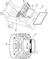
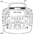
도 1c는 본 발명의 일 실시예에 따른 초음파 장치(100)의 외관을 나타내는 도면이다. 1C is a view showing an appearance of an
도 1c에 도시된 바와 같이, 본 발명의 일 실시예에 따른 초음파 장치(100)는 디스플레이부(120) 및 사용자 입력부(130), 프로브 연결부(180)를 포함할 수 있다. 1C, the
디스플레이부(120)는 대상체에 대한 초음파 영상을 표시할 수 있다. 예를 들어, 디스플레이부(120)는 B 모드(brightness mode) 영상, C 모드(color mode) 영상, D 모드(Doppler mode) 영상, 2차원 영상 또는 3차원 영상을 표시할 수 있다. The
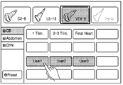
본 발명의 일 실시예에 따른 사용자 입력부(130)는 터치 스크린(131) 및 컨트롤 패널(132)을 포함할 수 있다. 본 발명의 일 실시예에 의하면, 터치 스크린(131)은, 초음파 영상, 이득 설정창, 기 설정된 이득 값의 목록 등을 표시할 수 있다. 또한, 터치 스크린(131)은, 초음파 장치(100)에 연결된 프로브의 식별 정보를 포함하는 프로브 목록, 사용자에 의해 설정된 복수의 파라미터 값들, 시스템 또는 사용자에 의해 기 설정된 프리셋 아이템 목록 등을 표시할 수 있다. The
본 발명의 일 실시예에 의하면, 터치 스크린(131)에 표시되는 초음파 영상이 디스플레이부(120)에 함께 표시될 수 있다. 이때, 사용자는 터치 스크린(131)을 통해 이득 값 또는 복수의 파라미터 값들을 조절하면서 초음파 영상의 변화를 관찰할 수도 있고, 디스플레이부(131)를 통해 대상체에 관한 초음파 영상을 세밀히 관찰할 수도 있다. The ultrasound image displayed on the
본 발명의 일 실시예에 따른 컨트롤 패널(132)은 트랙볼, 모드 선택 버튼(예컨대, M, CW, PW, PD, C, 2D, 3D, 4D 모드 등), 프로브 버튼, 전원 버튼 등의 하드웨어 버튼을 포함할 수 있으나, 이에 한정되는 것은 아니다. The
초음파 장치(100)는 적어도 하나 이상의 프로브 연결부(180)를 포함할 수 있다. 초음파 장치(100)는 프로브 연결부(180)에 연결되는 프로브의 식별 정보를 확인할 수 있다. 예를 들어, 초음파 장치(100)는 프로브에 기 저장된 프로브 식별 정보를 수신하거나 읽을 수 있다. 본 명세서에서 기술되는 프로브는 종류가 다양할 수 있다. The
이하에서는 초음파 장치(100)가 상기 각 구성을 이용하여 초음파 영상 및/또는 이득 값을 설정하기 위한 이득 설정 창을 제공하는 방법에 대해서 도 2를 참조하여 자세히 살펴 보기로 한다.Hereinafter, a method of providing a gain setting window for setting an ultrasound image and / or a gain value using the above-described configurations of the
도 2는 본 발명의 일 실시예와 관련된 초음파 장치의 정보 제공 방법을 설명하기 위한 순서도이다.2 is a flowchart illustrating an information providing method of an ultrasonic apparatus according to an embodiment of the present invention.
도 2를 참조하면, 본 발명의 일 실시예에 따른 정보 제공 방법은 도 1에 도시된 초음파 장치(100)에서 처리되는 단계들로 구성된다. 따라서, 이하에서 생략된 내용이라 하더라도 도 1에 도시된 초음파 장치(100)에 관하여 이상에서 기술된 내용은 도 2의 정보 제공 방법에도 적용됨을 알 수 있다.Referring to FIG. 2, an information providing method according to an embodiment of the present invention is comprised of steps processed in the
단계 S210에서, 초음파 장치(100)는 대상체에 대한 초음파 영상 데이터를 획득할 수 있다. 예를 들어, 초음파 장치(100)는 대상체로 초음파를 송신하고, 대상체로부터 수신된 초음파 응답 신호에 기초하여 초음파 영상 데이터를 생성할 수 있다. In step S210, the
단계 S220에서, 초음파 장치(100)는 초음파 영상 데이터의 이득 값을 설정하기 위한 이득 설정 창을 화면의 제 1 영역에 표시할 수 있다. 본 발명의 일 실시예에 따른 이득 값은 TGC(Time Gain Compensation) 값 및 LGC(Lateral Gain Compensation) 값 중 적어도 하나를 포함할 수 있다. In step S220, the
TGC(Time Gain Compensation) 값은 초음파 신호의 크기가 인체의 깊이에 따라 감소하는 것을 보상하는데 이용되는 값이다. LGC(Lateral Gain Compensation) 값은 각각 다른 초음파 빔의 전달 경로로 인하여 감쇠량의 차이가 고르지 못한 것을 보상하는데 이용되는 값이다. 이하에서는 설명의 편의상 TGC 값을 이득 값의 일례로 들어 설명하기로 한다. The TGC (Time Gain Compensation) value is a value used to compensate for the decrease in the size of the ultrasonic signal according to the depth of the human body. The LGC (Lateral Gain Compensation) is a value used to compensate for the unevenness in the attenuation due to the transmission path of the different ultrasonic beams. Hereinafter, for convenience of explanation, the TGC value will be described as an example of the gain value.
본 발명의 일 실시예에 따른 초음파 장치(100)는 이득 값을 설정할 수 있는 적어도 하나의 슬라이드 바(Slider bar)를 이득 설정 창에 표시할 수 있다. 예를 들어, 초음파 장치(100)는 초음파 영상의 깊이 방향을 따라 적어도 하나의 슬라이드 바를 이득 설정 창에 배열하여 표시할 수 있다. 깊이 방향은 초음파 장치(100)를 이용하여 진단하고자 하는 진단 대상의 경계면으로부터 시작하여, 연조직의 안쪽으로 깊이 값이 커지는 방향을 의미할 수 있다. The
한편, 본 발명의 일 실시예에 따른 슬라이드 바(slider bar)는, 사용자가 특정 깊이에 대한 이득 값을 각각 조절할 수 있도록 하는 GUI를 의미한다. Meanwhile, a slider bar according to an embodiment of the present invention means a GUI that allows a user to adjust a gain value for a specific depth, respectively.
본 발명의 일 실시예에 따른 적어도 하나의 슬라이드 바는 깊이 방향을 따라 일정한 간격으로 평행하게 배열될 수 있다. The at least one slide bar according to an embodiment of the present invention may be arranged in parallel at regular intervals along the depth direction.
본 발명의 일 실시예에 의하면, 초음파 영상 데이터 획득 시, 사용자에 의해 설정된 이득 값이 존재하지 않는 경우, 초음파 장치(100)는 대상체의 깊이 값에 따른 초기 이득 값을 제 1 영역에 표시할 수 있다. 이때, 초음파 장치(100)는 초기 이득 값을 적용하여 생성된 초음파 영상을 화면에 표시할 수도 있다. According to an embodiment of the present invention, when the gain value set by the user does not exist at the time of acquiring ultrasound image data, the
단계 S230에서, 초음파 장치는 이득 설정 창을 통해 사용자가 설정한 이득 값을 수신할 수 있다. 즉, 초음파 장치(100)는 이득 설정 창을 통해 사용자로부터 이득 값을 설정 받을 수 있는 것이다. In step S230, the ultrasonic apparatus can receive the gain value set by the user through the gain setting window. That is, the
본 발명의 일 실시예에 의하면, 초음파 장치(100)는 적어도 하나의 슬라이드 바에 대한 사용자의 터치 입력을 감지할 수 있다. 상기 터치 입력은 드래그 입력 또는 탭 입력일 수 있다. 예를 들어, 사용자는 슬라이드 바 상의 조절 버튼을 드래그(drag)하거나, 슬라이드 바 상의 특정 위치를 탭(tap) 할 수 있는 것이다. According to an embodiment of the present invention, the
"드래그(drag)"는 사용자가 손가락이나 터치 도구를 화면에 터치한 후 터치를 유지한 상태에서 손가락이나 터치 도구를 화면 내의 다른 위치로 이동시키는 동작을 의미한다. "탭(tap)"은 사용자가 손가락이나 터치 도구(예컨대, 전자 펜)를 이용하여 화면을 터치한 후 움직이지 않은 채 화면에서 즉시 들어올리는 동작을 나타낸다. "Drag" means an operation of moving a finger or a touch tool to another position in the screen while the user holds the touch after touching the finger or the touch tool on the screen. The "tap" indicates an operation in which the user immediately touches the screen using a finger or a touch tool (e.g., an electronic pen) and immediately lifts it from the screen without moving.
초음파 장치(100)는 감지된 터치 입력의 위치에 대응하는 이득 값을 추출할 수 있다. 즉, 초음파 장치(100)는 슬라이드 바가 나타내는 깊이 값에 대해 사용자가 설정한 이득 값을 획득할 수 있는 것이다.The
본 발명의 또 다른 실시예에 의하면, 초음파 장치(100)는 이득 설정 창 안에서 깊이 방향(즉, 적어도 하나의 슬라이드 바에 수직하는 방향)으로 드래그하는 사용자의 드래그 입력을 감지할 수 있다. 초음파 장치(100)는 드래그 입력의 위치(예컨대, 드래그 입력이 감지된 픽셀의 좌표)에 기초하여, 초음파 영상의 깊이 값 각각에 대응하는 이득 값을 추출할 수 있다. According to another embodiment of the present invention, the
예를 들어, 사용자가 이득 설정 창 안에서 슬라이드 바에 수직하는 방향으로 직선 또는 곡선을 그리면서 드래그하는 경우, 초음파 장치(100)는 드래그된 각각의 위치에 해당하는 이득 값을 추출하여, 각 깊이 값에 대한 이득 값으로 설정할 수 있다. For example, when the user drags a straight line or a curve while drawing in a direction perpendicular to the slide bar in the gain setting window, the
한편, 본 발명의 일 실시예에 따른 초음파 장치(100)는 드래그 입력의 위치에 기초하여 추출된 이득 값에 따라, 적어도 하나의 슬라이드 바 상의 조절 버튼을 이동하여 표시할 수도 있다.Meanwhile, the
단계 S240에서, 초음파 장치(100)는 이득 설정 창을 통해 사용자에 의해 설정된 이득 값이 적용된 초음파 영상을 화면의 제 2 영역에 표시할 수 있다. 예를 들어, 초음파 장치(100)는, 사용자에 의해 설정된 이득 값을 초음파 영상 데이터에 실시간으로 적용하여 대상체에 대한 초음파 영상을 새롭게 생성하거나, 초음파 영상의 일부를 변경할 수 있다. In step S240, the
따라서, 본 발명의 일 실시예에 의하면, 사용자는 이득 조절 창을 통해 이득 값을 조절하면서, 조절된 이득 값이 적용된 초음파 영상을 실시간으로 관측할 수 있다. 사용자가 이득 값을 높게 설정할수록 초음파 영상이 밝아지고, 이득 값을 낮게 설정할수록 초음파 영상이 어두워질 수 있다.Therefore, according to an embodiment of the present invention, the user can observe the ultrasound image applied with the adjusted gain value in real time while adjusting the gain value through the gain adjustment window. As the user sets the gain value higher, the ultrasound image becomes brighter, and when the gain value is set lower, the ultrasound image may become darker.
이하에서는 도 3 내지 도 7를 참조하여 초음파 장치(100)가 TGC 값을 설정 받는 방법에 대해서 구체적으로 살펴보기로 한다. Hereinafter, a method of setting the TGC value by the
도 3은 본 발명의 일 실시예와 관련된 초음파 장치의 TGC(Time Gain Compensation) 설정 시작 화면의 일례를 나타내는 도면이다. 3 is a view showing an example of a TGC (Time Gain Compensation) setting start screen of the ultrasonic apparatus according to an embodiment of the present invention.
도 3에 도시된 바와 같이, 초음파 장치(100)는 놉 버튼으로 제공하던 TGC 설정 버튼을 터치 스크린 상에서 제공할 수 있다. 따라서, 사용자가 터치 스크린 상의 TGC 설정 버튼(310)을 터치하는 경우, 초음파 장치(100)는 TGC 값을 설정 받을 수 있는 TGC 설정 모드로 진입하게 된다. As shown in FIG. 3, the
도 4는 본 발명의 일 실시예에 관련된 이득 값을 설정하기 위한 이득 설정 창을 나타내는 도면이다. 4 is a diagram illustrating a gain setting window for setting a gain value according to an embodiment of the present invention.
도 4에 도시된 바와 같이, 초음파 장치(100)는 초음파 영상 데이터의 이득 값을 설정하기 위한 이득 설정 창(410)을 화면의 제 1 영역에 표시할 수 있다. 이때, 이득 설정 창(410)은 복수의 깊이 값에 대한 이득 값을 각각에 설정할 수 있는 복수의 슬라이드 바를 포함할 수 있다. 복수의 슬라이드 바는 깊이 방향으로 평행하게 배열될 수 있다. 4, the
초음파 장치(100)는 대상체에 대한 초음파 영상(420)을 화면의 제 2 영역에 표시할 수 있다. 본 발명의 일 실시예에 의하면, 초음파 장치(100)는 초음파 영상(420)이 표시되는 제 2 영역과 이득 설정 창(410)이 표시되는 제 1 영역을 근접하게 배치함으로써, 사용자가 TGC 값을 설정할 때 불필요하게 시선이 분산되는 것을 방지할 수 있다. The
또한, 본 발명의 일 실시예에 의하면, 초음파 장치(100)는 이득 설정 창(410)을 통해 설정된 이득 값에 대응하는 이득 라인(430)을 획득하여 제 2 영역에 표시할 수 있다. 이에 관하여는 도 6을 참조하여 후에 좀 더 자세히 살펴 보기로 한다. According to an embodiment of the present invention, the
도 5a, 5b 및 5c는 본 발명의 일 실시예에 따른 사용자로부터 이득 값을 설정 받는 화면을 나타내는 도면이다.5A, 5B, and 5C are views illustrating a screen for setting a gain value from a user according to an exemplary embodiment of the present invention.
본 발명의 일 실시예에 의하면, 사용자는 적어도 하나의 슬라이드 바를 터치하여 슬라이드 바 상의 조절 버튼을 이동시키거나, 슬라이드 바에 수직하는 방향으로 드래그하는 제스처에 의해 TGC 값을 설정할 수 있다. According to an embodiment of the present invention, a user can set a TGC value by touching at least one slide bar to move an adjustment button on the slide bar, or by a gesture to drag in a direction perpendicular to the slide bar.
도 5a에 도시된 바와 같이, 사용자는 슬라이드 바 상의 조절 버튼을 좌우로 드래그할 수 있다. 이때, 초음파 장치(100)는 사용자의 드래그 입력을 감지하고, 드래그가 종료되는 위치에 조절 버튼이 표시되도록 할 수 있다. As shown in FIG. 5A, the user can drag the adjustment button on the slide bar to the left and right. At this time, the
만일, 사용자가 제 1 슬라이드 바(510) 상의 조절 버튼을 왼쪽 방향으로 드래그하는 경우, 제 1 슬라이드 바(510)가 나타내는 깊이 값에 대응하는 TGC 값이 작아질 수 있다. 이 경우, 제 1 슬라이드 바(510)가 나타내는 깊이 값에 대응하는 초음파 영상 부분의 휘도가 낮아져 어둡게 표시될 수 있다. If the user drags the adjustment button on the
본 발명의 일 실시예에 의하면, 사용자는 깊이 값에 따라 각각 할당된 슬라이드 바의 조절 버튼을 이동함으로써, 특정 깊이 값에 대한 TGC 값을 개별적으로 조절할 수 있게 된다. According to an embodiment of the present invention, the user can individually adjust the TGC values for the specific depth values by moving the adjustment buttons of the slide bars assigned to the depth bars.
도 5b, 도 5c에 도시된 바와 같이, 사용자는 직선 또는 곡선 형태로 이득 설정 창 위에서 선을 그리듯 드래그함으로써, 복수의 깊이 값 각각에 대응하는 TGC 값을 전체적으로 한번에 설정할 수도 있다. 이때, 본 발명의 일 실시예에 의하면, 초음파 장치(100)는 사용자의 드래그 입력을 감지하고, 드래그 입력이 감지된 위치로 슬라이드 바 상의 조절 버튼을 이동시켜 표시할 수도 있다. As shown in FIGS. 5B and 5C, the user may set a TGC value corresponding to each of the plurality of depth values as a whole, by dragging a line on the gain setting window in a straight line or a curve shape. At this time, according to an embodiment of the present invention, the
도 6은 본 발명의 일 실시예와 관련된 이득 값에 대응하는 이득 라인을 나타내는 도면이다. 6 is a diagram illustrating a gain line corresponding to a gain value associated with an embodiment of the present invention.
본 발명의 일 실시예에 의하면, 초음파 장치(100)는 이득 설정 창(610)을 통해 설정된 이득 값에 대응하는 이득 라인(630)을 획득하여, 초음파 영상(620)과 함께 표시할 수 있다. According to an embodiment of the present invention, the
예를 들어, 초음파 장치(100)는 복수의 슬라이드 바 상의 조절 버튼(611)의 위치(즉, 조절 버튼이 나타내는 이득 값)를 연결하여 이득 라인(630)을 획득할 수 있다. 이때, 초음파 장치(100)는, 제 1 슬라이드 바 상의 이득 값과 제 2 슬라이드 바 상의 이득 값을 이용하여, 제 1 슬라이드 바와 제 2 슬라이드 바 사이의 이득 값을 보간 계산할 수 있다. For example, the
또한, 초음파 장치(100)는, 사용자가 이득 설정 창(610) 위에서 직선 또는 곡선 형태로 드래그함으로써 이득 값을 설정한 경우, 드래그된 위치에 따라 이득 라인(630)을 획득할 수도 있다.In addition, the
본 발명의 일 실시예에 따른 초음파 장치(100)는, 이득 설정 창(610)을 통해 사용자가 설정한 이득 값에 대응하는 이득 라인(430)을 초음파 영상(420)의 깊이 값의 위치에 맞춰 초음파 영상(620) 옆에 표시해 줌으로써, 사용자가 이득 라인(630)의 형태 또는 이득 라인(630)의 기울기 등을 직관적으로 확인할 수 있게 해 준다. The
한편, 도 6에는 이득 라인(630)이 초음파 영상(620)의 우측에 표시되는 일례를 도시하였으나, 이에 한정되는 것은 아니다. 즉, 이득 라인(630)은 초음파 영상(620)의 하단에 표시될 수도 있고, 상단에 표시될 수도 있고, 좌측에 표시될 수도 있다. 6 shows an example in which the
도 7은 본 발명의 일 실시예와 관련된 기 설정된 이득 값의 목록을 나타내는 도면이다. 7 is a diagram illustrating a list of predetermined gain values associated with an embodiment of the present invention.
도 7에 도시된 바와 같이, 본 발명의 일 실시예에 따른 초음파 장치(100)는 적어도 하나의 기 설정된 이득 값의 목록(710)을 화면의 제 3 영역에 표시할 수 있다. 본 발명의 일 실시예에 따른 기 설정된 이득 값은 사용자에 의해 기 설정된 이득 값일 수도 있고, 시스템에서 기 설정된 이득 값일 수도 있다. As shown in FIG. 7, the
본 발명의 일 실시예에 의하면, 기 설정된 이득 값의 목록은 기 설정된 이득 값에 대응하는 이득 라인의 이미지 형태로 표시될 수 있다. 이때, 이득 라인은 실선, 점선, 일점 쇄선 등 다양하게 표현될 수 있다. 한편, 기 설정된 이득 값은 복수의 슬라이드 바가 포함된 이미지 형태로 표시될 수도 있다. According to an embodiment of the present invention, the predetermined list of gain values may be displayed in the form of an image of a gain line corresponding to a predetermined gain value. At this time, the gain line can be expressed in various ways such as a solid line, a dotted line, and a dotted chain line. Meanwhile, the predetermined gain value may be displayed in the form of an image including a plurality of slide bars.
본 발명의 일 실시예에 의하면, 상기 목록(710)에 포함되는 기 설정된 이득 값은, 초음파 장치(100)에서 자동으로 선택될 수도 있고, 사용자에 의해 수동으로 선택될 수도 있다. According to an embodiment of the present invention, the predetermined gain value included in the
예를 들어, 초음파 장치(100)는 전형적으로 이용 빈도가 높은 기 설정된 이득 값을 추출하여, 상기 목록(710) 상에 표시할 수도 있고, 사용자에 의해 선택된 기 설정된 이득 값을 상기 목록(710) 상에 포함시켜 표시할 수도 있다. For example, the
한편, 초음파 장치(100)는 프로브 설정 정보, 애플리케이션 정보, 대상체 정보 중 적어도 하나에 기초하여, 화면의 제 3 영역에 표시되는 기 설정된 이득 값을 추출할 수도 있다. 예를 들어, 사용자가 1D 선형 프로브를 선택한 경우, 초음파 장치(100)는 1D 선형 프로브와 맵핑하여 저장된 기 설정된 이득 값을 추출하여 상기 목록(710)에 표시할 수 있다. 또한, 초음파 장치(100)는 사용자가 애플리케이션 중 OB(OBstetrics, 산과)를 선택한 경우, 사용자가 선택한 애플리케이션과 관련하여 기 설정된 이득 값을 추출하여 상기 목록(710)에 표시할 수도 있다. On the other hand, the
본 발명의 일 실시예에 따른 초음파 장치(100)는 바디마커, 애플리케이션 정보, 및 프로브 설정 정보 중 적어도 하나를 상기 목록(710)에 더 포함하여 표시할 수도 있다. The
애플리케이션 정보란 초음파 진단을 실행하는 초음파 영상 진단과(診斷科) 또는 진단 부위에 관한 정보를 의미한다. 초음파 영상 진단과에는 OB(OBstetrics, 산과), GYN(GYNecology, 부인과), PD(PeDiatrics, 소아과), CS(ChestSurgery, 흉부외과), RD(Radiology, 방사선과), NS(NeuroSurgery, 신경외과), Abdomen(복부) 등이 있을 수 있다.Application information refers to information about ultrasound imaging (diagnosis department) or diagnosis site that performs ultrasound diagnosis. Ultrasonographic imaging includes OB (OBstetrics), GYN (Gynecology, gynecology), PD (PeDiatrics, pediatrics), CS (ChestSurgery, thoracic surgery), RD (Radiology, Radiology), NS (NeuroSurgery, Neurosurgery) (Abdomen), and the like.
바디마커는 초음파가 주사된 위치 또는 대상체 등을 나타내는 도형을 의미한다. 바디마커의 일례로, 간 모양, 심장 모양, 자궁 모양 등이 있을 수 있다. 프로브 설정 정보는 초음파 신호를 출력하는 프로브에 관해 설정된 정보를 의미할 수 있다. 예를 들어, 저주파의 곡면형 프로브가 이용된 경우, 해당 기 설정된 이득 값에 'low freq convex' 가 더 표시될 수 있고, 고주파의 선형 프로브가 이용된 경우, 해당 기 설정된 이득 값에 'high frequency linear'가 더 표시될 수 있다. The body marker means a figure indicating a position or an object to which the ultrasonic wave is scanned. Examples of body markers include liver, heart, uterine, and the like. The probe setting information may refer to information set for a probe outputting an ultrasonic signal. For example, when a low-frequency curved probe is used, 'low freq convex' may be further displayed in the predetermined gain value, and when a high frequency linear probe is used, a 'high frequency linear 'can be displayed.
본 발명의 일 실시예에 의하면, 초음파 장치(100)는, 상기 목록(710)에서 하나의 기 설정된 이득 값을 선택 받을 수 있다. 그리고 초음파 장치(100)는 선택된 기 설정된 이득 값을 이득 설정 창에 표시하고, 선택된 기 설정된 이득 값이 적용된 초음파 영상을 제 2 영역에 표시할 수 있다. 이때, 초음파 장치(100)는 선택된 기 설정된 이득 값에 대한 사용자의 추가 설정을 입력 받을 수 있다. 즉, 사용자는 이득 설정 창에 표시된 이득 값의 전부 또는 일부를 수정하여, 이득 값을 좀 더 면밀하게 조정할 수 있다.According to an embodiment of the present invention, the
본 발명의 일 실시예에 따른 초음파 장치(100)는 기 설정된 TGC 값의 유형을 몇 가지 제공함으로써, 사용자가 간편하게 TGC 값을 설정할 수 있도록 한다.The
한편, 초음파 장치(100)는 이득 설정 창에 설정된 이득 값을 초기화할 수 있는 초기화 버튼(720)을 제공할 수도 있다. 초음파 장치(100)는 초기화 버튼(720)에 대한 터치 입력이 감지되는 경우, 이득 설정 창에 초기 이득 값을 표시하고, 초기 이득 값이 반영된 초음파 영상을 제 2 영역에 표시할 수 있다. Meanwhile, the
도 8은 본 발명의 일 실시예와 관련된 초음파 장치의 이득 값 저장 방법을 설명하기 위한 순서도이다. 8 is a flowchart illustrating a method of storing a gain value of an ultrasonic apparatus according to an embodiment of the present invention.
단계 S810에서, 초음파 장치(100)는 이득 설정 창을 통해 설정된 이득 값에 대한 사용자의 저장 요청을 수신할 수 있다. 사용자의 저장 요청은 화면에 표시된 특정 아이콘을 터치함으로써 수행될 수도 있고, 물리적 버튼을 선택함으로써 수행될 수도 있다. In step S810, the
단계 S820에서, 초음파 장치(100)는 이득 설정 창을 통해 설정된 이득 값을 메모리(160)에 저장할 수 있다. 본 발명의 일 실시예에 의하면, 초음파 장치(100)는, 프로브 설정 정보 및 애플리케이션 정보 중 적어도 하나와 이득 설정 창을 통해 설정된 이득 값을 매핑하여 저장할 수도 있다. 또한, 초음파 장치(100)는, 이득 설정 창을 통해 설정된 이득 값을 초음파 영상과 관련하여 미리 설정된 적어도 하나의 파라미터 값과 연결하여 저장할 수 있다. 이에 관하여는 후에 자세히 살펴보기로 한다. In step S820, the
단계 S830에서, 초음파 장치(100)는 저장된 이득 값의 이미지를 제 3 영역에 표시할 수 있다. 예를 들어, 사용자가 저장 버튼을 선택하는 경우, 초음파 장치(100)는 현재 이득 설정 창에 표시된 이득 값을 메모리(160)에 저장하고, 기 설정된 이득 값의 목록에, 현재 이득 설정 창에 표시된 이득 값을 포함시켜 표시할 수도 있다. 이에 관하여는 도 9a, 9b 및 9c를 참조하여 좀 더 자세히 살펴보기로 한다. In step S830, the
도 9a, 9b 및 9c는 본 발명의 일 실시예와 관련된 이득 값을 저장하기 위한 GUI의 일례를 나타내는 도면이다. 9A, 9B and 9C are diagrams illustrating an example of a GUI for storing gain values associated with an embodiment of the present invention.
도 9a에 도시된 바와 같이, 본 발명의 일 실시예에 의하면, 초음파 장치(100)는 터치 스크린을 통해 저장 버튼(930)을 출력할 수 있다. 이때, 초음파 장치(100)는 저장 버튼(930)에 대한 사용자의 터치 입력을 감지할 수 있다. 이 경우, 초음파 장치(100)는 저장 모드로 진입한다. As shown in FIG. 9A, according to an embodiment of the present invention, the
도 9b에 도시된 바와 같이, 저장 모드 중에 초음파 장치(100)는 기 설정된 이득 값의 목록(940) 중 현재 이득 설정 창(910)에 표시된 이득 값이 표시될 수 있는 영역(또는, 슬롯)에 대한 식별 표시를 제공할 수도 있다. 예를 들어, 초음파 장치(100)는 기 설정된 이득 값의 이미지가 표시된 버튼(941, 942, 943)의 주변에 노란색 테두리를 표시할 수 있다. 9B, in the storage mode, the
만일, 사용자로부터 세 번째 버튼(943)에 대한 선택이 수신되는 경우, 도 9c에 도시된 바와 같이, 초음파 장치(100)는 현재 이득 설정 창(910)에 표시된 이득 값을 메모리(160)에 저장하면서, 현재 이득 설정 창(910)에 표시된 이득 값의 이미지를 세 번째 버튼(943)에 표시할 수 있다. 9C, the
도 9c에서는 세 번째 버튼(943)의 이미지가 변경되는 일례를 도시하였으나, 구현 예에 따라서, 초음파 장치(100)는 현재 이득 설정 창(910)에 표시된 이득 값의 이미지가 표시된 버튼을 새로 생성하고, 세 번째 버튼(943) 다음에 추가하여 표시할 수도 있다. 9C shows an example in which the image of the
따라서, 본 발명의 일 실시예에 따른 초음파 장치(100)는, 저장 당시 해당 TGC 값에 대응하는 이득 곡선을, 특정 버튼을 통해 표시해 줄 수 있으므로, 사용자가 저장된 TGC 값(또는, TGC 라인)을 직관적으로 확인할 수 있게 한다. Therefore, the
한편, 본 발명의 일 실시예에 따른 초음파 장치(100)는 TGC 설정 모드를 종료할 수 있는 종료 버튼(950)을 터치 스크린을 통해서 제공할 수도 있다. 종료 버튼(950)에 대한 사용자의 터치 입력이 감지되는 경우, 초음파 장치(100)는 TGC 설정 모드를 종료할 수 있다. Meanwhile, the
본 발명의 또 다른 실시예에 의하면, 초음파 장치(100)는 소정 시간 이상 사용자의 터치 입력이 감지되지 않는 경우, TGC 설정 모드를 자동으로 종료할 수도 있다. According to another embodiment of the present invention, when the touch input of the user is not detected for a predetermined time or longer, the
도 10은 본 발명의 일 실시예와 관련된 LGC(Lateral Gain Compensation) 값을 설정하기 위한 이득 설정 창을 나타내는 도면이다.10 is a diagram illustrating a gain setting window for setting a value of LGC (Lateral Gain Compensation) according to an embodiment of the present invention.
위에서는 이득 값의 일례로 TGC 값을 들어 설명하였으나, 도 3 내지 도 9에서 기재한 TGC 값에 관한 설명은 LGC 값에도 적용될 수 있음은 물론이다. In the above description, the TGC value is described as an example of the gain value, but it goes without saying that the description of the TGC value described in FIG. 3 to FIG. 9 can also be applied to the LGC value.
도 10에 도시된 바와 같이, 본 발명의 일 실시예에 따른 초음파 장치(100)는 LGC 설정 창을 터치 스크린 상에 제공할 수 있다. 예를 들어, 초음파 장치(100)는 LGC 값을 설정할 수 있는 복수의 슬라이드 바를 LGC 설정 창 안에 평행하게 배열할 수 있다. As shown in FIG. 10, the
이때, 사용자는 슬라이드 바 각각을 조절하여 LGC 값을 개별적으로 설정할 수도 있고, 슬라이드 바에 수직하는 방향(측 방향)으로 직선 또는 곡선을 그리듯이 드래그함으로써, 소정 범위의 LGC 값 전체를 한번에 설정할 수도 있다. At this time, the user may individually set the LGC value by adjusting each of the slide bars, or may set all of the LGC values within a predetermined range at once by dragging a straight line or a curved line in the direction (lateral direction) perpendicular to the slide bar.
본 발명의 일 실시예에 따른 초음파 장치(100)는 사용자에 의해 설정된 LGC 값이 반영된 초음파 영상을 실시간으로 화면에 표시해 줄 수도 있다. 또한, 초음파 장치(100)는 사용자에 의해 설정된 LGC 값을 메모리(160)에 저장할 수 있고, 기 설정된 LGC 값의 목록을 화면에 표시해 줄 수도 있다. 이에 관한 구체적인 설명은 TGC 값에 대한 설명 부분과 유사하므로, 생략하기로 한다. 한편, 도면에는 TGC 설정 창과 LGC 설정 창이 각각 다른 화면에 표시되어 있으나, 본 발명의 일 실시예에 따른 초음파 장치(100)는 TGC 설정 창과 LGC 설정 창을 한 화면에서 표시할 수도 있다.The
도 11은 본 발명의 일 실시예와 관련된 초음파 장치의 정보 제공 방법을 설명하기 위한 순서도이다.11 is a flowchart for explaining an information providing method of an ultrasonic apparatus according to an embodiment of the present invention.
단계 S1110에서, 초음파 장치(100)는, 기 설정된 이득 값의 목록을 화면에 표시할 수 있다. 기 설정된 이득 값의 목록은, 이득 라인 형태의 이미지로 표시될 수도 있고, 기 설정된 이득 값을 나타내는 숫자나 문자로 표시될 수도 있다. 기 설정된 이득 값의 목록을 표시하는 것과 관련된 구체적인 설명은 도 7에 대한 설명 부분과 중복되므로 생략하기로 한다. In step S1110, the
본 발명의 일 실시예에 따른 초음파 장치(100)는, 적어도 하나의 기 설정된 이득 값을 메모리(160) 또는 개인화 서버(예컨대, 클라우드 서버)에서 추출하고, 추출된 적어도 하나의 기 설정된 이득 값을 이용하여 목록을 구성할 수 있다. 즉, 본 발명의 일 실시예에 따른 초음파 장치(100)는, 외부 저장 매체 또는 내부 저장 매체로부터 기 설정된 이득 값의 목록을 획득할 수 있다.The
본 발명의 또 다른 실시예에 의하면, 초음파 장치(100)는, 유무선 통신을 통해 외부 장치로부터 기 설정된 이득 값의 목록을 수신할 수도 있다. According to another embodiment of the present invention, the
단계 S1120에서, 초음파 장치(100)는, 목록에서 하나의 기 설정된 이득 값을 선택 받을 수 있다. 예를 들어, 초음파 장치(100)는 하나의 기 설정된 이득 값에 대한 사용자의 터치 입력(예컨대, 탭 제스처, 스와이프 제스처, 플릭 제스처 등) 또는 음성 명령을 감지할 수 있다. In step S1120, the
단계 S1130에서, 초음파 장치(100)는, 선택된 기 설정된 이득 값을 대상체에 대한 초음파 영상 데이터에 적용할 수 있다. 그리고 초음파 장치(100)는, 선택된 기 설정된 이득 값이 적용된 초음파 영상을 화면에 표시할 수 있다. In step S1130, the
본 발명의 일 실시예에 따른 초음파 장치(100)는, 사용자에 의해 선택된 기 설정된 이득 값을 이득 설정 창에 표시할 수도 있다. 예를 들어, 초음파 장치(100)는, 선택된 기 설정된 이득 값에 따라, 이득 설정 창 안에 표시된 적어도 하나의 슬라이드 바를 이동시킬 수 있다. The
본 발명의 일 실시예에 따른 초음파 장치(100)는, 이득 설정 창에 표시된 기 설정된 이득 값에 대한 사용자의 추가 설정을 수신할 수 있다. 예를 들어, 사용자는 이득 설정 창 안에 표시된 적어도 하나의 슬라이드 바를 조절하여, 이득 설정 창에 표시된 기 설정된 이득 값을 좀 더 세밀하게 조절할 수 있는 것이다. The
본 발명의 일 실시예에 따른 초음파 장치(100)는, 사용자에 의해 추가 설정된 이득 값을 저장할 수 있다. 이때, 본 발명의 일 실시예에 따른 초음파 장치(100)는, 내부 저장 매체 또는 외부 저장 매체(예컨대, USB 메모리, 광 디스크)에 사용자에 의해 추가 설정된 이득 값을 저장할 수 있다. The
이때, 본 발명의 일 실시예에 따른 초음파 장치(100)는 내부 저장 매체 또는 외부 저장 매체에 저장된 이득 값을 기 설정된 이득 값의 목록에 추가하여 표시할 수도 있다. At this time, the
한편, 본 발명의 일 실시예에 따른 초음파 장치(100)는, 기 설정된 이득 값 또는 기 설정된 이득 값의 목록을 유무선 통신을 통해 외부 장치로 전송할 수 있다. 본 발명의 일 실시예에 따른 외부 장치(100)는, 사용자의 디바이스(예컨대, 휴대폰, 스마트폰, 노트북 컴퓨터, 태블릿 PC, 전자북 단말기 등), 또 다른 초음파 장치, 개인화 서버(예컨대, 클라우드 서버) 등을 포함할 수 있으나, 이에 한정되는 것은 아니다. Meanwhile, the
도 12는 본 발명의 또 다른 실시예와 관련된 초음파 장치의 정보 제공 방법을 설명하기 위한 순서도이다.12 is a flowchart illustrating an information providing method of an ultrasonic apparatus according to another embodiment of the present invention.
단계 S1210에서, 초음파 장치(100)는 대상체에 대한 초음파 영상 데이터를 획득할 수 있다. In step S1210, the
단계 S1220에서, 초음파 장치(100)는, 획득된 초음파 영상 데이터의 이득 값을 설정하기 위한 이득 설정 창을 화면의 제 1 영역에 표시할 수 있다. In step S1220, the
단계 S1230에서, 초음파 장치(100)는, 획득된 초음파 영상 데이터에 기초하여, 상기 대상체에 대한 초음파 영상을 화면의 제 2 영역에 표시할 수 있다. In step S1230, the
단계 S1240에서, 초음파 장치(100)는, 기 설정된 이득 값의 목록을 화면의 제 3 영역에 표시할 수 있다. 본 발명의 일 실시예에 의하면, 초음파 장치(100)는, 기 설정된 이득 값의 목록을 외부 저장 매체로부터 획득하여 표시할 수도 있다. In step S1240, the
본 발명의 일 실시예에 따른 초음파 장치(100)는 목록에서 하나의 기 설정된 이득 값을 선택 받을 수 있다. 그리고 초음파 장치(100)는 선택된 기 설정된 이득 값을 이득 설정 창에 표시하고, 선택된 기 설정된 이득 값이 적용된 초음파 영상을 제 2 영역에 표시할 수도 있다. The
예를 들어, 도 9a에 도시된 바와 같이, 초음파 장치(100)는 하나의 화면을 통해, 이득 설정 창(910), 초음파 영상(920), 기 설정된 이득 값의 목록(940)을 표시할 수 있다. 이 경우, 사용자는 이득 설정 창(910)에 표시된 슬라이드 바를 직접 조절하여, TGC 값 또는 LGC 값을 설정할 수도 있고, 기 설정된 이득 값의 목록(940)에 표시된 하나의 기 설정된 이득 값(예컨대, 943)을 선택할 수도 있다.For example, as shown in FIG. 9A, the
사용자가 목록(940)에 표시된 하나의 기 설정된 이득 값(예컨대, 943)을 선택하는 경우, 초음파 장치(100)는 선택된 기 설정된 이득 값(예컨대, 943)을 이득 설정 창(940)에 표시할 수 있다. 그리고, 초음파 장치(100)는 이득 설정 창(940)에 표시된 하나의 기 설정된 이득 값에 대한 추가 설정을 사용자로부터 입력 받을 수 있다. 본 발명의 일 실시예에 따른 초음파 장치(100)는, 이득 설정 창(910)을 통해 추가 설정된 이득 값을 메모리(160) 또는 외부 저장 매체에 저장하고, 저장된 이득 값의 이미지를 기 설정된 이득 값의 목록(940)에 표시할 수 있다. When the user selects one predetermined gain value (e.g., 943) displayed in the
한편, 본 발명의 일 실시예에 따른 초음파 장치(100)는, 선택된 기 설정된 이득 값(예컨대, 943)에 맵핑된 적어도 하나의 파라미터 값을 표시할 수 있다. 본 발명의 다른 실시예에 의하면, 초음파 장치(100)는, 선택된 기 설정된 이득 값(예컨대, 943)에 맵핑된 적어도 하나의 파라미터 값을 확인하고, 확인된 적어도 하나의 파라미터 값을 시스템에 적용할 수 있다. 즉, 초음파 장치(100)는 선택된 기 설정된 이득 값(예컨대, 943)에 맵핑된 적어도 하나의 파라미터 값으로 초음파 시스템의 설정을 변경할 수 있다. 이에 관하여 도 13 내지 도 17을 참조하여 좀 더 자세히 살펴보기로 한다. Meanwhile, the
도 13은 본 발명의 일 실시예에 따른 초음파 영상과 관련된 설정 파라미터들의 일례를 나타내는 도면이다. 13 is a diagram illustrating an example of configuration parameters related to an ultrasound image according to an embodiment of the present invention.
도 13에 도시된 바와 같이, 본 발명의 일 실시예에 의하면, 초음파 영상과 관련하여 설정할 수 있는 파라미터는, 주파수(frequency)(1305), 다이나믹 레인지(dynamic range)(1310), 프레임 평균(Frame average)(1315), 리젝트 레벨(reject level)(1320), 그레이 맵(gray map)(1325), 공간 컴파운드(spatial compound)(1330), DMR+(Dynamic Magnetic Resonance)(1335), 하모닉(Harmonic)(1340), 스캔 영역(Scan Area)(1345), 에지 강화(edge enhance)(1350), 속도(speed)(1355), 파워(Power)(1360), 선 밀도(Line Density)(1365), FSI(Full Spectrum Image)(1370), 초점 수(Focus Number)(1375), 전체 이득 값(gain)(1380) 및 깊이(depth)(1385) 중 적어도 하나를 포함할 수 있다. 13, according to an exemplary embodiment of the present invention, parameters that can be set in relation to an ultrasound image include a
본 발명의 일 실시예에 따른 주파수(frequency)(1305)는 프로브에 인가하는 송수신 주파수를 변경할 수 있는 파라미터를 의미한다. 예를 들어, 사용자는 Pen, Gen, 및 Res 중 하나를 선택함으로써, 주파수(frequency)(1305)의 파라미터 값을 설정할 수 있다. A
본 발명의 일 실시예에 따른 다이나믹 레인지(dynamic range)(1310)는, 입력 신호의 최소 값과 최대 값의 비율을 변경하여 명함을 조절하는 파라미터이다. 예를 들어, 사용자는 50~200 사이의 값 중 하나를 선택함으로써, 다이나믹 레인지(dynamic range)(1310)의 파라미터 값을 설정할 수 있다. A
본 발명의 일 실시예에 따른 프레임 평균(Frame average)(1315)은, 초음파 영상의 랜덤 노이즈를 줄이는 파라미터이다. 예를 들어, 사용자는 0~15 사이의 값 중 하나를 선택함으로써, 프레임 평균(Frame average)(1315)의 파라미터 값을 설정할 수 있다. A
본 발명의 일 실시예에 따른 리젝트 레벨(reject level)(1320)은, 초음파 영상의 노이즈를 제거하는 파라미터이다. 예를 들어, 사용자는 1~32 사이의 값 중 하나를 선택함으로써, 리젝트 레벨(reject level)(1320)의 파라미터 값을 설정할 수 있다. A
본 발명의 일 실시예에 따른 그레이 맵(gray map)(1325)은, 초음파 영상의 포스트 커브(post curve)를 변경하여, 그레이 스케일을 결정하는 파라미터이다. 예를 들어, 사용자는 1~13 사이의 값 중 하나를 선택함으로써, 그레이 맵(gray map)(1325)의 파라미터 값을 설정할 수 있다. 이에 관하여는 도 16을 참조하여 후에 좀 더 살펴 보기로 한다. A
본 발명의 일 실시예에 따른 공간 컴파운드(spatial compound)(1330)는, 초음파 영상의 밀도를 조절하는 파라미터이다. 예를 들어, 사용자는 low / med / high 중 하나를 선택함으로써, 공간 컴파운드(spatial compound)(1330)의 파라미터 값을 설정할 수 있다.The
본 발명의 일 실시예에 따른 DMR+(Dynamic Magnetic Resonance)(1335)는, 초음파 영상을 후처리하는 파리미터로, 노이즈를 저하시키고 에지를 강조할 수 있는 파라미터이다. 예를 들어, 사용자는 1~5 사이의 값 중 하나를 선택함으로써, DMR+(Dynamic Magnetic Resonance)(1335)의 파라미터 값을 설정할 수 있다.DMR + (Dynamic Magnetic Resonance) 1335 according to an embodiment of the present invention is a parameter for post-processing an ultrasound image, and is a parameter capable of reducing noise and emphasizing an edge. For example, the user can set the parameter value of the DMR + (Dynamic Magnetic Resonance) 1335 by selecting one of the values between 1 and 5.
본 발명의 일 실시예에 따른 하모닉(Harmonic)(1340)은, 고주파를 이용하여 초음파 영상을 최적화하는 파라미터이다. 예를 들어, 사용자는 On, off 중 하나를 선택함으로써 하모닉(Harmonic)(1340)의 파라미터 값을 설정할 수 있다. The harmonic 1340 according to an exemplary embodiment of the present invention is a parameter for optimizing an ultrasound image using a high frequency. For example, the user can set the parameter value of the harmonic 1340 by selecting one of On and off.
본 발명의 일 실시예에 따른 스캔 영역(Scan Area)(1345)은, 초음파 영상의 가로 넓이(%)를 조절하는 파라미터이다. 예를 들어, 사용자는 40~100 사이의 값 중 하나를 선택함으로써, 스캔 영역(Scan Area)(1345)의 파라미터 값을 설정할 수 있다.A
본 발명의 일 실시예에 따른 에지 강화(edge enhance)(1350)는, 조직이나 장기의 경계면을 뚜렷하게 표현하는 파라미터이다. 예를 들어, 사용자는 -3 ~ 3 사이의 값 중 하나를 선택함으로써, 에지 강화(edge enhance)(1350)의 파라미터 값을 설정할 수 있다.
본 발명의 일 실시예에 따른 속도(speed)(1355)는, 조직의 속도를 조절하여 해상도를 높이는 파라미터이다. 예를 들어, 사용자는 1440~1620 (m/s) 사이의 값 중 하나를 선택함으로써, 속도(speed)(1355)의 파라미터 값을 설정할 수 있다. The
본 발명의 일 실시예에 따른 파워(Power)(1360)는, 초음파 출력의 세기를 선택하는 파리미터이다. 예를 들어, 사용자는 10~100 사이의 값 중 하나를 선택함으로써, 파워(Power)(1360)의 파라미터 값을 설정할 수 있다. The
본 발명의 일 실시예에 따른 선 밀도(Line Density)(1365)는, 초음파 영상의 밀도를 조절하는 파라미터이다. 예를 들어, 사용자는 low/mid1/mid2/high 중 하나를 선택함으로써, 선 밀도(Line Density)(1365)의 파라미터 값을 설정할 수 있다. The
본 발명의 일 실시예에 따른 FSI(Full Spectrum Image)(1370)는, 주파수를 섞는 비율을 조절하는 파라미터이다. 예를 들어, 사용자는 1~3 사이의 값 중 하나를 선택함으로써, FSI(Full Spectrum Image)(1370)의 파라미터 값을 설정할 수 있다.The FSI (Full Spectrum Image) 1370 according to an embodiment of the present invention is a parameter for adjusting the mixing ratio of frequencies. For example, the user can set the parameter value of the FSI (Full Spectrum Image) 1370 by selecting one of the values from 1 to 3.
본 발명의 일 실시예에 따른 초점 수(Focus Number)(1375)는, 초점의 위치 및 개수를 설정하는 파라미터이다. 예를 들어, 사용자는 1~4 사이의 값 중 하나를 선택함으로써, 초점 수(Focus Number)(1375)의 파라미터 값을 설정할 수 있다.A
본 발명의 일 실시예에 따른 전체 이득 값(gain)(1380)은, 초음파 영상의 밝기를 조절하는 파라미터이다. 예를 들어, 사용자는 1~100 사이의 값 중 하나를 선택함으로써, 전체 이득 값(gain)(1380)의 파라미터 값을 설정할 수 있다.The
본 발명의 일 실시예에 따른 깊이(depth)(1385)는, 스캔하는 초음파 영상의 깊이를 조절하는 파라미터이다. 본 발명의 일 실시예에 따른 깊이(depth)(1380)의 파라미터 값은 프로브의 종류에 따를 수 있다. 예를 들어, 컨벡스(convex) 프로브의 경우, 사용자는 6~30 cm 사이의 값을 선택함으로써, 깊이(depth)(1380)에 대한 파라미터 값을 설정할 수 있다. A
도 14a 및 14b는 본 발명의 일 실시예에 따른 초음파 영상과 관련된 파라미터 값을 설정하는 GUI의 일례를 나타내는 도면이다. 14A and 14B are views showing an example of a GUI for setting a parameter value related to an ultrasound image according to an embodiment of the present invention.
본 발명의 일 실시예에 따른 초음파 장치(100)는 초음파 영상과 관련된 각각의 파라미터 값을 설정하기 위한 설정 창(1400)을 제공할 수 있다. The
예를 들어, 도 14a에 도시된 바와 같이, 초음파 장치(100)는 화면에, 주파수(frequency)(1305), 다이나믹 레인지(dynamic range)(1310), 프레임 평균(Frame average)(1315), 리젝트 레벨(reject level)(1320), 그레이 맵(gray map)(1325), DMR+(1335), 하모닉(Harmonic)(1340), 속도(speed)(1355), FSI(1370) 등의 파라미터 값을 설정하기 위한 설정 창(1400)을 제공할 수 있다. For example, as shown in FIG. 14A, the
또한, 도 14b에 도시된 바와 같이, 스캔 영역(Scan Area)(1345), 에지 강화(edge enhance)(1350), 파워(Power)(1360), 선 밀도(Line Density)(1365) 등의 파라미터 값을 설정하기 위한 설정 창(1400)을 제공할 수도 있다. 14B, parameters such as a
본 발명의 일 실시예에 의하면, 초음파 장치(100)는 설정 창(1400)을 통해 사용자가 입력(또는 선택)한 파라미터 값을 감지할 수 있다. 그리고 초음파 장치(100)는, 사용자의 저장 요청에 따라, 사용자에 의해 입력(또는 선택)된 파라미터 값을 저장할 수 있다. 이와 관련하여, 도 15a, 15b, 15c 및 15d를 참조하기로 한다. According to an embodiment of the present invention, the
도 15a, 15b, 15c 및 15d는 미리 설정된 적어도 하나의 파라미터 값을 저장하는 GUI의 일례를 나타내는 도면이다. 15A, 15B, 15C, and 15D are views showing an example of a GUI storing at least one parameter value set in advance.
도 15a에 도시된 바와 같이, 본 발명의 일 실시예에 의하면, 사용자가 터치 스크린(131) 상의 특정 아이콘을 터치하거나, 컨트롤 패널(control panel)(132) 상의 특정 버튼을 선택하는 경우, 초음파 장치(100)는 사용자에 의해 설정되는 파라미터 값을 저장할 수 있는 GUI(1500)를 제공할 수 있다. 15A, according to an embodiment of the present invention, when a user touches a specific icon on the
예를 들어, 초음파 장치(100)는 사용자로부터 프로브 버튼(1510) 선택이 감지되는 경우, 터치 스크린(131)에 이득 값 또는 초음파 영상과 관련된 적어도 하나의 파라미터 값을 조절할 수 있는 GUI(1500)를 제공할 수 있다. For example, the
도 15b에 도시된 바와 같이, 초음파 장치(100)는 초음파 장치(100)에 연결된 적어도 하나의 프로브의 식별 정보를 포함하는 프로브 목록(1520)을 GUI(1500)의 소정 영역에 표시할 수 있다. 예를 들어, 초음파 장치(100)에 프로브 1(C2-8), 프로브 2(L5-13), 프로브 3(VE4-8)이 연결되어 있는 경우, 초음파 장치(100)는 프로브 목록(1520)에 프로브 1(C2-8), 프로브 2(L5-13), 프로브 3(VE4-8)의 식별 정보를 표시할 수 있다. 프로브의 식별 정보는 프로브를 식별하기 위한 정보로서, 프로브의 이미지, 프로브 명, 프로브의 종류 등이 포함될 수 있다. The
본 발명의 일 실시예에 의하면, 초음파 장치(100)는, 프로브 목록(1520)에서 적어도 하나의 프로브를 선택하는 사용자의 입력을 감지할 수 있다. 예를 들어, 사용자는 프로브 목록(1520)에서 프로브 3(VE4-8)을 선택할 수 있다. According to one embodiment of the present invention, the
또한, 초음파 장치(100)는, 애플리케이션(진단과)의 목록(1530)을 GUI(1500)의 소정 영역에 표시하고, 사용자로부터 애플리케이션에 관한 선택을 수신할 수도 있다. 예를 들어, 사용자는 애플리케이션 목록에서 Abdomen(복부)을 선택할 수 있다. The
이 때, 본 발명의 일 실시예에 따른 초음파 장치(100)는 사용자에 의해 선택된 프로브 3(VE4-8)에 대응하는 프리셋의 목록을 표시할 수 있다. 또한, 본 발명의 다른 실시예에 따른 초음파 장치(100)는 사용자에 의해 선택된 프로브 3(VE4-8) 및 애플리케이션(Abdomen)에 대응하는 프리셋의 목록을 표시할 수도 있다. 이때, 본 발명의 일 실시예에 따른 프리셋의 목록은 시스템 상에서 기 설정되어 변경 불가능한 파라미터들을 포함하는 시스템 프리셋과 사용자에 의해 임의로 설정된 파라미터들을 포함하는 사용자 프리셋을 포함할 수 있다. At this time, the
본 발명의 일 실시예에 따른 초음파 장치(100)는, 시스템 상에서 기 설정되어 변경 불가능한 파라미터들이 맵핑되어 있는 시스템 프리셋 이 표시되는 디폴트 영역(1540)과 사용자가 임의로 설정한 파라미터들이 맵핑되어 있는 사용자 프리셋이 표시되는 임의 영역(1550)을 GUI(1500) 상에 제공할 수 있다. The
사용자가 프로브 및 애플리케이션 중 적어도 하나에 대응하는 프리셋의 목록 중 하나의 프리셋 아이템(예컨대, Fetal Heart)을 선택하고, 소정 버튼(1560)을 터치하는 경우, 초음파 장치(100)는 선택된 프리셋 아이템(Fetal Heart)에 대응하는 기 설정된 파라미터들을 제공할 수 있다. When the user selects a preset item (e.g., Fetal Heart) from the list of the presets corresponding to at least one of the probe and the application and touches the
예를 들어, 도 15c에 도시된 바와 같이, 초음파 장치(100)는 프리셋 아이템(Fetal Heart)에 맵핑하여 기 설정된 주파수(frequency)(1305), 프레임 평균(Frame average)(1315), 그레이 맵(gray map)(1325), 하모닉(Harmonic)(1340), 선 밀도(Line Density)(1365), 초점 수(Focus Number)(1375) 등을 표시할 수 있다. 이때, 사용자는 화면에 표시된 각각의 파라미터 값들을 변경하여 새로운 사용자 프리셋을 생성할 수도 있다. 새롭게 생성된 사용자 프리셋은 임의 영역(1550)에 표시될 수 있다. 이때, 사용자는 새롭게 생성된 사용자 프리셋 명을 설정할 수 있다. For example, as shown in FIG. 15C, the
예를 들어, 제 1 사용자는 'user1'이란 이름을 갖는 사용자 프리셋을 생성하고, 제 1 사용자가 설정한 복수의 파라미터 값을 'user1' 에 맵핑하여 저장할 수 있다. 또한, 제 2 사용자는 'user2'이란 이름을 갖는 사용자 프리셋에 제 2 사용자가 설정한 복수의 파라미터 값을 맵핑하여 저장할 수도 있다. 한편, 제 3 사용자가 태아의 얼굴과 관련하여 파라미터 값들을 설정한 경우, 제 3 사용자는 'Face'란 이름을 갖는 사용자 프리셋에 태아의 얼굴과 관련하여 설정한 파라미터 값들을 맵핑하여 저장할 수 있다.For example, the first user may generate a user preset having the name 'user1', and may store the plurality of parameter values set by the first user in 'user1'. Also, the second user may map and store a plurality of parameter values set by the second user in a user preset having the name 'user2'. On the other hand, when the third user sets the parameter values in relation to the face of the fetus, the third user can map and store the parameter values set in relation to the face of the fetus in the user preset having the name 'Face'.
또한, 사용자는 이득 값을 설정하고, 설정된 이득 값을 추가하여 새로운 사용자 프리셋을 생성할 수도 있다. 예를 들어, 사용자가 화면에서 TGC 버튼을 터치하는 경우, 초음파 장치(100)는 이득 값(예컨대, TGC)을 설정할 수 있는 설정 창을 제공할 수 있다. The user may also set a gain value and add a set gain value to create a new user preset. For example, when the user touches the TGC button on the screen, the
도 15d에 도시된 바와 같이, 초음파 장치(100)는 이득 설정 창을 제공하고, 이득 설정 창을 통해 사용자로부터 이득 값을 입력 받을 수 있다. 초음파 장치(100)가 이득 설정 창을 통해 사용자로부터 이득 값을 입력 받는 방법에 대해서는 위에서 설명하였으므로, 구체적인 설명은 생략하기로 한다. As shown in FIG. 15D, the
초음파 장치(100)가 사용자로부터 설정된 이득 값에 대한 저장 요청을 수신하는 경우, 초음파 장치(100)는 설정된 이득 값을 포함하는 사용자 프리셋을 생성할 수 있다. 이 경우, 본 발명의 일 실시예에 의하면, 사용자에 의해 설정된 이득 값은, 사용자에 의해 선택된 프로브(예컨대, 프로브 3) 및 애플리케이션 정보(예컨대, Abdomen) 중 적어도 하나와 맵핑되어 사용자 프리셋으로 저장될 수 있다. 그리고 본 발명의 일 실시예에 의하면, 사용자에 의해 설정된 이득 값은, 기 설정된 파라미터들과 함께 사용자 프리셋으로 임의 영역(1560)에 저장될 수 있다. 따라서, 본 발명의 일 실시예에 따른 초음파 장치(100)는, 사용자가 프로브 별로 자주 사용되는 TGC 라인을 만들어 사용자 프리셋에 저장할 수 있도록 해 준다. 예를 들어, 사용자는 경동맥 초음파에서 자주 사용되는 TGC 라인을 경동맥 초음파에 사용되는 프로브에 연결하여 저장할 수 있다. 이때, 초음파 장치(100)는, 서로 맵핑되어 있는 프로브의 식별 정보, 초음파 영상과 관련된 파라미터들, 이득 값을 포함하는 프리셋 맵핑 테이블을 생성하고, 프리셋 맵핑 테이블을 메모리(160)에 저장할 수 있다. When the
한편, 도 15a, 15b, 15c 및 15d에서는 프로브 및 애플리케이션을 먼저 선택한 후에 파라미터 값을 조절하거나 TGC 값을 설정하는 방법을 일례로 설명하였으나, 본 발명의 구현 예예 따라 파라미터 값 또는 TGC 값을 먼저 설정한 이후에 프로브 또는 애플리케이션을 선택하여 연결할 수도 있다. 15A, 15B, 15C, and 15D, a method of adjusting a parameter value or setting a TGC value after first selecting a probe and an application has been described as an example. However, according to an embodiment of the present invention, You can then select and connect probes or applications.
이하에서는, 본 발명의 일 실시예에 따른 초음파 장치(100)가 프로브와 맵핑되어 저장된 이득 값을 자동으로 추출하여 시스템에 적용하는 방법에 대해서 살펴보기로 한다. Hereinafter, a method of automatically extracting a gain value mapped with a probe and extracting the stored gain value and applying the same to a system will be described.
도 16은 본 발명의 일 실시예에 따른 프로브의 식별 정보에 기초한 초음파 장치의 정보 제공 방법을 설명하기 위한 순서도이다. 16 is a flowchart for explaining an information providing method of an ultrasound system based on identification information of probes according to an embodiment of the present invention.
단계 S1610에서, 초음파 장치(100)는, 초음파 장치(100)에 연결된 프로브의 식별 정보를 확인할 수 있다. 예를 들어, 초음파 장치(100)는 프로브의 메모리에 저장된 프로브의 식별 정보를 수신함으로써, 연결된 프로브의 식별 정보(예컨대, 프로브 명, 프로브 아이디, 프로브 종류 등)를 확인할 수 있다. In step S1610, the
한편, 초음파 장치(100)에 복수의 프로브가 연결되어 있는 경우, 초음파 장치(100)는, 복수의 프로브의 식별 정보를 확인하고, 복수의 프로브의 식별 정보를 포함하는 프로브 목록을 표시할 수도 있다. On the other hand, when a plurality of probes are connected to the
단계 S1620에서, 초음파 장치(100)는, 프로브의 식별 정보에 대응하는 기 설정된 이득 값을 추출할 수 있다. 예를 들어, 초음파 장치(100)는, 프로브의 식별 정보를 기초로, 프리셋 맵핑 테이블에서 프로브의 식별 정보와 맵핑되어 있는 기 설정된 이득 값을 추출할 수 있다. In step S1620, the
한편, 초음파 장치(100)는, 초음파 장치(100)에 연결된 복수의 프로브의 식별 정보를 포함하는 프로브 목록에서, 하나의 프로브의 식별 정보를 선택 받을 수 있다. 이때, 초음파 장치(100)는 선택된 프로브의 식별 정보에 대응하는 기 설정된 이득 값을 추출할 수도 있다. Meanwhile, the
본 발명의 일 실시예에 의하면, 초음파 장치(100)는, 프로브의 식별 정보에 대응하는 복수의 기 설정된 이득 값을 추출할 수도 있다. 이 경우, 초음파 장치(100)는, 복수의 기 설정된 이득 값을 포함하는 기 설정된 이득 값의 목록을 화면에 표시할 수 있다. 이때, 본 발명의 일 실시예에 따른 초음파 장치(100)는, 기 설정된 이득 값의 목록에서 하나의 기 설정된 이득 값을 선택 받을 수도 있다. According to the embodiment of the present invention, the
본 발명의 일 실시예에 의하면, 프로브의 식별 정보에 대응하는 복수의 기 설정된 이득 값은 복수의 사용자 프리셋에 각각 포함되어 있을 수 있다. 즉, 기 설정된 이득 값이 다른 파라미터들과 함께 사용자 프리셋으로 저장되어 있을 수 있다. 이 경우, 초음파 장치(100)는 프로브의 식별 정보에 대응하는 사용자 프리셋 목록을 표시하고, 사용자 프리셋 목록으로부터 하나의 사용자 프리셋을 선택 받을 수도 있다. According to an embodiment of the present invention, a plurality of predetermined gain values corresponding to the identification information of the probe may be included in each of the plurality of user presets. That is, the predetermined gain value may be stored as a user preset together with other parameters. In this case, the
본 발명의 일 실시예에 의하면, 초음파 장치(100)는 진단과를 나타내는 애플리케이션 정보를 입력 받을 수 있다. 예를 들어, 애플리케이션 정보에는, OB(OBstetrics, 산과), GYN(GYNecology, 부인과), PD(PeDiatrics, 소아과), CS(ChestSurgery, 흉부외과), RD(Radiology, 방사선과), NS(NeuroSurgery, 신경외과), Abdomen(복부) 등이 있을 수 있으나, 이에 한정되는 것은 아니다. According to an embodiment of the present invention, the
본 발명의 일 실시예에 따른 초음파 장치(100)는 프로브의 식별 정보 및 사용자에 의해 선택된 애플리케이션 정보에 대응하는 기 설정된 이득 값을 추출할 수도 있다. The
단계 S1630에서, 초음파 장치(100)는, 기 설정된 이득 값을 초음파 영상 데이터에 적용할 수 있다. In step S1630, the
예를 들어, 초음파 장치(100)가 사용자에 의해 선택된 프로브를 이용하여, 대상체에 대한 초음파 영상 데이터를 획득하는 경우, 초음파 장치(100)는, 사용자에 의해 선택된 프로브에 대응하는 기 설정된 이득 값을 초음파 영상 데이터에 적용할 수 있다. 즉, 본 발명의 일 실시예에 따른 초음파 장치(100)는, 프로브와 맵핑되어 저장된 이득 값을 자동으로 추출하여 시스템에 적용할 수 있다.For example, when the
본 발명의 일 실시예에 의하면, 초음파 장치(100)는, 초음파 장치(100)에 연결된 프로브의 식별 정보에 대응하는 기 설정된 이득 값을 화면의 소정 영역에 표시할 수도 있다. According to an embodiment of the present invention, the
초음파 장치(100)에 연결된 프로브가 복수 개 존재하는 경우, 초음파 장치(100)는 복수 개의 프로브 중 사용자에 의해 선택된 프로브의 식별 정보에 대응하는 기 설정된 이득 값을 화면에 표시할 수 있다. 이때, 본 발명의 일 실시예에 의하면, 초음파 장치(100)는, 화면에 표시된 기 설정된 이득 값에 대한 사용자의 추가 설정을 입력 받을 수 있다. 즉 사용자는 선택된 프로브에 맵핑된 기 설정된 이득 값을 확인하고, 기 설정된 이득 값을 좀 더 세밀하게 조절할 수 있다. When there are a plurality of probes connected to the
이하에서는, 프로브의 식별 정보에 대응하는 사용자 프리셋에 다양한 파라미터들과 함께 이득 값이 저장되어 있는 경우에 대해서 도 17 및 도 18을 참조하여 자세히 살펴보기로 한다. Hereinafter, a case where gain values are stored together with various parameters in a user preset corresponding to identification information of a probe will be described in detail with reference to FIGS. 17 and 18. FIG.
도 17a, 17b, 18a 및 18b는 사용자에 의해 선택된 사용자 프리셋에 대응하는 파라미터 값 및 이득 값을 나타내는 도면이다. 17A, 17B, 18A and 18B are diagrams showing parameter values and gain values corresponding to user presets selected by the user.
본 발명의 일 실시예에 의하면, 초음파 장치(100)는, 선택된 프로브의 식별 정보 및 애플리케이션 정보에 대응하는 프리셋 목록을 표시할 수 있다. 이때, 프리셋 목록은, 초음파 영상과 관련하여 미리 설정된 적어도 하나의 파라미터 값 및 이득 값을 포함하는 적어도 하나의 사용자 프리셋을 포함할 수 있다. 도 17a에 도시된 바와 같이, 사용자가 프리셋 목록에서 'user 1'을 선택하는 경우, 초음파 장치(100)는 'user 1' 에 맵핑되어 있는 기 설정된 파라미터 값들 및 이득 값을 시스템에 적용하거나 화면에 표시할 수 있다. According to an embodiment of the present invention, the
예를 들어, 도 17b에 도시된 바와 같이, 초음파 장치(100)는 'user 1' 에 맵핑되어 있는 파라미터들(예컨대, DMR+: on, Frequency: Res, Dynamic Range: 117, Frame Avg.: 5, Reject Level: 1, gray map: 9, Line Density: Med, Power: 96, Scan Area: 100, Fucus Number: 1 등) 및 TCG 라인을 표시할 수 있다. For example, as shown in FIG. 17B, the
한편, 도 18a에 도시된 바와 같이, 사용자가 프리셋 목록에서 'user 2' 를 선택하는 경우, 초음파 장치(100)는 'user 2' 에 맵핑되어 있는 기 설정된 파라미터 값들 및 이득 값을 시스템에 적용하거나 화면에 표시할 수 있다.18A, when the user selects 'user 2' in the preset list, the
예를 들어, 도 18b에 도시된 바와 같이, 초음파 장치(100)는 'user 2' 에 맵핑되어 있는 파라미터들(예컨대, DMR+: on, Frequency: Pen, Dynamic Range: 120, Frame Average: 10, Reject Level: 2, gray map: 10, Chroma Map: 3, Power: 80, Scan Area: 100 등) 및 TGC 라인을 표시할 수 있다. For example, as shown in FIG. 18B, the
이때, 사용자는 사용자 프리셋에 포함되어 있는 각각의 파리미터 값들 및 TGC 라인을 편집(예컨대, 삭제, 추가, 변경)할 수도 있다. 또한, 사용자는 사용자 프리셋의 명칭을 변경할 수도 있다. 예를 들어, 사용자는 'User 1'을 'face'로 변경할 수 있다. At this time, the user may edit (e.g., delete, add, change) the respective parameter values and the TGC line included in the user preset. In addition, the user may change the name of the user preset. For example, the user can change 'User 1' to 'face'.
본 발명의 일 실시예에 의하면, 초음파 장치(100)는, 초음파 영상과 관련하여 미리 설정되는 복수의 파라미터 중 적어도 하나의 파라미터에 관한 목록을 표시할 수도 있다. 예를 들어, 초음파 장치(100)는 그레이 스케일을 결정하기 위한 그레이 맵 목록을 제공하거나, 3차원 볼륨 데이터에서 소정 영역을 선택하기 위한 커브 목록을 제공할 수 있다. 도 19a, 도 19b, 도 20a 및 도 20b를 참조하여 좀 더 자세히 살펴보기로 한다. According to an embodiment of the present invention, the
도 19a 및 19b는 본 발명의 일 실시예에 따른 기 설정된 그레이 맵 목록을 설명하기 위한 도면이다. 19A and 19B are views for explaining a predetermined gray map list according to an embodiment of the present invention.
도 19a에 도시된 바와 같이, 본 발명의 일 실시예에 의하면, 사용자는 그레이 스케일을 결정하기 위한 그레이 맵(1900)의 형태를 조절할 수 있다. 예를 들어, 사용자는 그레이 맵(1900)의 형태를 직선 형태, 포물선 형태, S자 형태 등으로 다양하게 설정할 수 있다. 한편, 사용자의 요청이 있는 경우, 초음파 장치(100)는 사용자에 의해 설정된 그레이 맵을 저장할 수 있다. 본 발명의 일 실시예에 따른 그레이 맵은 2차원 영상에 대한 그레이 맵일 수도 있고, 3차원 영상에 대한 그레이 맵일 수도 있다.As shown in FIG. 19A, according to an embodiment of the present invention, the user can adjust the shape of the
도 19b에 도시된 바와 같이, 초음파 장치(100)는, 기 설정된 그레이 맵 목록을 화면에 표시할 수 있다. 기 설정된 그레이 맵 목록은, 라인 형태의 이미지로 표시될 수도 있고, 숫자나 문자로 표시될 수도 있다. As shown in FIG. 19B, the
본 발명의 일 실시예에 따른 초음파 장치(100)는, 적어도 하나의 기 설정된 그레이 맵을 메모리(160) 또는 개인화 서버(예컨대, 클라우드 서버)에서 추출하고, 추출된 적어도 하나의 기 설정된 그레이 맵을 이용하여 목록을 구성할 수 있다. 즉, 본 발명의 일 실시예에 따른 초음파 장치(100)는, 외부 저장 매체 또는 내부 저장 매체로부터 기 설정된 그레이 맵의 목록을 획득할 수 있다.The
본 발명의 또 다른 실시예에 의하면, 초음파 장치(100)는, 유무선 통신을 통해 외부 장치로부터 기 설정된 그레이 맵의 목록을 수신할 수도 있다. According to another embodiment of the present invention, the
한편, 초음파 장치(100)는, 그레이 맵 목록에서 하나의 기 설정된 그레이 맵을 선택 받을 수 있다. 예를 들어, 초음파 장치(100)는 하나의 기 설정된 그레이 맵에 대한 사용자의 터치 입력(예컨대, 탭 제스처, 스와이프 제스처, 플릭 제스처 등) 또는 음성 명령을 감지할 수 있다. 이때, 초음파 장치(100)는, 선택된 기 설정된 그레이 맵을 대상체에 대한 초음파 영상 데이터에 적용할 수 있다. On the other hand, the
본 발명의 일 실시예에 따른 초음파 장치(100)는, 선택된 그레이 맵을 화면에 표시하고, 선택된 그레이 맵에 대한 사용자의 추가 설정을 수신할 수도 있다. 즉, 사용자는 선택된 그레이 맵의 형태를 더 세밀하게 조절할 수 있는 것이다. The
도 20a 및 20b는 본 발명의 일 실시예에 따른 기 설정된 커브 목록을 나타내는 도면이다. 20A and 20B are diagrams illustrating a predetermined curve list according to an embodiment of the present invention.
도 20a에 도시된 바와 같이, 본 발명의 일 실시예에 의하면, 사용자는 3차원 볼륨 데이터에서 소정 영역을 선택하기 위한 커브(2000)의 형태를 조절할 수 있다. 본 발명의 일 실시예에 따른 커브의 형태는 다양할 수 있다. 한편, 초음파 장치(100)는, 사용자의 요청이 있는 경우, 사용자에 의해 설정된 커브의 형태를 저장할 수 있다. As shown in FIG. 20A, according to an embodiment of the present invention, a user can adjust the shape of a
도 20b에 도시된 바와 같이, 초음파 장치(100)는, 기 설정된 커브 목록을 화면에 표시할 수 있다. 기 설정된 커브 목록은, 이미지 형태로 표시될 수 있다. 본 발명의 일 실시예에 따른 초음파 장치(100)는, 적어도 하나의 기 설정된 커브 이미지를 메모리(160) 또는 개인화 서버(예컨대, 클라우드 서버)에서 추출하고, 추출된 적어도 하나의 기 설정된 커브 이미지를 이용하여 커브 목록을 구성할 수 있다. 본 발명의 또 다른 실시예에 의하면, 초음파 장치(100)는, 유무선 통신을 통해 외부 장치로부터 커브 목록을 수신할 수도 있다. As shown in FIG. 20B, the
본 발명의 일 실시예에 의하면, 초음파 장치(100)는, 커브 목록에, 커브와 관련된 애플리케이션 종류(예컨대, OB), 바디마커(예컨대, 태아 얼굴) 등을 함께 표시해 줄 수도 있다.According to one embodiment of the present invention, the
한편, 초음파 장치(100)는, 커브 목록에서 하나의 커브를 선택 받을 수 있다. 이때, 초음파 장치(100)는, 선택된 커브를 대상체에 대한 초음파 영상 데이터에 적용할 수 있다.On the other hand, the
본 발명의 일 실시예에 따른 초음파 장치(100)는, 이득 값(예컨대, TGC 또는 LGC) 이외에 초음파 영상과 관련된 다양한 파라미터들의 목록을 제공함으로써, 사용자가 초음파 영상과 관련된 다양한 파라미터들을 간편하게 설정할 수 있도록 한다. The
도 21은, 본 발명의 일 실시예에 따르는, 초음파 장치의 정보 제공 방법을 설명하기 위한 순서도이다. 21 is a flowchart for explaining an information providing method of an ultrasonic apparatus according to an embodiment of the present invention.
단계 S2110에서, 초음파 장치(100)는, 대상체에 대한 초음파 영상을 화면에 표시할 수 있다. In step S2110, the
본 발명의 일 실시예에 의하면, 초음파 영상은 실시간으로 프로브를 통해 획득되는 실시간 영상일 수 있다. 또한, 초음파 영상은, 메모리 또는 서버에 기 저장되어 있던 영상일 수도 있다. According to an embodiment of the present invention, the ultrasound image may be a real-time image obtained through a probe in real time. In addition, the ultrasound image may be a video image previously stored in a memory or a server.
단계 S2120에서, 초음파 장치(100)는, 기 정의된 조건 정보에 따라 슬라이드 바의 개수를 결정할 수 있다. 슬라이드 바는, 화면에 표시된 초음파 영상의 TGC 값을 조절하기 위한 조절 버튼을 포함할 수 있다. 이때, TGC 값은, 초음파 영상의 깊이에 따른 밝기 값을 조절하기 위한 값이다. In step S2120, the
한편, 슬라이드 바는 초음파 영상의 깊이 값과 일대일로 매칭될 수 있으므로, 깊이들 간의 간격은 슬라이드 바들 간의 간격과 동일한 의미로 사용될 수 있다.On the other hand, since the slide bar can be matched with the depth value of the ultrasound image on a one-to-one basis, the interval between the depths can be used to have the same meaning as the interval between the slide bars.
본 발명의 일 실시예에 의하면, 기 정의된 조건 정보는, 슬라이드 바를 화면에 표시하기 위한 조건에 관한 정보를 의미할 수 있다. 기 정의된 조건 정보는, 슬라이드 바의 개수 정보, 슬라이드 바들을 표시하기 위한 깊이들 간의 간격 정보, 슬라이드 바들이 표시되는 위치에 관한 정보(예컨대, 초음파 영상 우측 영역에 슬라이드 바들 표시, 새로운 설정 창 위에 슬라이드 바들 표시 등), 슬라이드 바를 표시하는 시간에 관한 정보 등을 포함할 수 있다. 예를 들어, 기 정의된 조건 정보에는, 프로브의 종류에 따른 슬라이드 바들 간의 간격 정보(예컨대, 프로브의 종류와 슬라이드 바들 간의 간격을 매칭한 테이블), 대상체의 종류에 따른 슬라이드 바들 간의 간격 정보(예컨대, 진단 부위와 슬라이드 바들 간의 간격을 매칭한 테이블), 슬라이드 바가 표시되는 일부 깊이 구간에 관한 정보 등이 포함될 수 있다. According to an embodiment of the present invention, predefined condition information may mean information about a condition for displaying a slide bar on a screen. The predefined condition information includes information on the number of slide bars, interval information between the depths for displaying the slide bars, information on the position where the slide bars are displayed (for example, display of slide bars on the right side region of the ultrasound image, A slide bar display, etc.), information on the time for displaying the slide bar, and the like. For example, the predefined condition information includes information on the interval between the slide bars according to the type of the probe (for example, a table that matches the type of the probe with the interval between the slide bars), interval information between the slide bars according to the type of the object , A table that matches the interval between the diagnostic portion and the slide bars), information on some depth intervals in which the slide bar is displayed, and the like.
본 발명의 일 실시예에 의하면, 기 정의된 조건 정보는 사용자에 의해 기 정의된 것일 수도 있고, 초음파 시스템에 의해 기 정의된 것일 수도 있다. 한편, 기 정의된 조건 정보는 사용자의 설정에 의해 변경 가능하다. According to an embodiment of the present invention, the predefined condition information may be predefined by the user or predefined by the ultrasound system. On the other hand, predefined condition information can be changed by user's setting.
본 발명의 일 실시예에 의하면, 초음파 장치(100)는, 기 정의된 조건 정보에 포함된 슬라이드 바들을 표시하기 위한 깊이들 간의 간격 정보를 이용하여, 슬라이드 바의 개수를 결정할 수 있다(도 22 참조). According to an embodiment of the present invention, the
이때, 본 발명의 일 실시예에 의하면, 기 정의된 깊이들 간의 간격은 전체적으로 일정할 수도 있고, 구간별로 상이할 수도 있다. 예를 들어, 초음파 영상에 병변이 존재하는 경우, 병변이 존재하는 영역의 TGC 값을 사용자가 세밀하게 조절할 수 있도록, 다른 영역에 비해 병변이 존재하는 영역에 대응하는 슬라이드 바들 간의 간격이 짧을 수 있다. In this case, according to an embodiment of the present invention, the interval between predefined depths may be entirely constant or may be different according to intervals. For example, if there is a lesion in the ultrasound image, the interval between the slide bars corresponding to the region where the lesion is present may be short so that the user can finely adjust the TGC value of the lesion-present region .
본 발명의 일 실시예에 의하면, 초음파 장치(100)는, 프로브의 종류에 기초하여, 슬라이드 바의 개수를 결정할 수도 있다. 예를 들어, 초음파 장치(100)는 기 정의된 조건 정보에서 프로브의 종류에 대응하는 슬라이드 바들 간의 간격을 확인할 수 있다. 예컨대, 선형 프로브의 경우, 슬라이드 바들 간의 간격이 1cm의 깊이 간격일 수 있다. 초음파 장치(100)는, 프로브의 종류(예컨대, 선형 프로브)에 대응하는 슬라이드 바들 간의 간격(예컨대, 1cm의 깊이 간격)과 초음파 영상의 전체 깊이(예컨대, 6cm)에 기초하여, 슬라이드 바의 개수(예컨대, 6개)를 결정할 수 있다. According to the embodiment of the present invention, the
본 발명의 일 실시예에 의하면, 초음파 장치(100)는, 대상체의 종류에 기초하여, 슬라이드 바의 개수를 결정할 수도 있다. 초음파 장치(100)는 대상체의 종류를 확인할 수 있다. 예를 들어, 초음파 장치(100)는, 초음파 장치(100)에 연결된 프로브의 종류, 사용자에 의해 입력되는 바디마커, 및 초음파 영상에 포함된 해부학적 구조 정보 중 적어도 하나에 기초하여, 대상체의 종류(예컨대, 진단 부위)를 확인할 수 있다. According to the embodiment of the present invention, the
초음파 장치(100)는, 기 정의된 조건 정보에서 진단 부위에 대응하는 슬라이드 바들 간의 간격을 확인할 수 있다. 예를 들어, 대상체가 '복부'인 경우, 슬라이드 바들 간의 간격이 1cm의 깊이 간격으로 정의되어 있을 수 있다. 또한, 대상체가 '갑상선'인 경우, 슬라이드 바들 간의 간격이 '2cm'의 깊이 간격으로 정의되어 있을 수 있다. 초음파 장치(100)는 진단 부위에 대응하는 슬라이드 바들 간의 간격과 초음파 영상의 전체 깊이에 기초하여, 슬라이드 바의 개수를 결정할 수 있다. The
또한, 초음파 장치(100)는 기 정의된 조건 정보에서 진단 부위에 대응하는 슬라이드 바의 개수를 확인할 수도 있다. 예를 들어, 대상체가 '복부'인 경우 슬라이드 바 10개, 대상체가 '갑상선'인 경우 슬라이드 바 8개 등과 같이, 기 정의된 조건 정보에 진단 부위에 따른 슬라이드 바의 개수가 정의되어 있을 수 있다.In addition, the
단계 S2130에서, 초음파 장치(100)는, 결정된 슬라이드 바의 개수에 기초하여, 초음파 영상의 복수의 깊이에 대응하는 복수의 슬라이드 바를 화면에 표시할 수 있다. 예를 들어, 초음파 장치(100)는, 결정된 개수만큼의 복수의 슬라이드 바를 초음파 영상의 특정 깊이와 일대일로 매칭하여 표시할 수 있다.In step S2130, the
본 발명의 일 실시예에 의하면, 슬라이드 바는 GUI(Graphical User Interface) 형태로 표시될 수 있다. 따라서, 사용자는 화면에 표시되는 슬라이드 바의 조절 버튼을 위치를 조절함으로써, 초음파 영상의 깊이에 따른 TGC 값(밝기 값)을 조절할 수 있다. According to an embodiment of the present invention, the slide bar may be displayed in a GUI (Graphical User Interface) form. Accordingly, the user can adjust the TGC value (brightness value) according to the depth of the ultrasound image by adjusting the position of the adjustment button of the slide bar displayed on the screen.
본 발명의 일 실시예에 의하면, 초음파 장치(100)는, 초음파 영상의 전체 깊이에 대응하는 영역에 복수의 슬라이드 바를 표시할 수도 있고, 초음파 영상의 일부 깊이 구간에 대응하는 영역에 복수의 슬라이드 바를 표시할 수 있다. According to an embodiment of the present invention, the
예를 들어, 초음파 장치(100)는, 초음파 영상의 전체 깊이 중에서 일부 깊이를 선택할 수 있다. 그리고 초음파 장치(100)는, 선택된 일부 깊이에 대응하는 슬라이드 바들을 화면에 표시할 수 있다. 이때, 일부 깊이는, 관심 영역이 포함된 깊이 구간이거나 병변이 포함된 깊이 구간일 수 있다. For example, the
본 발명의 일 실시예에 의하면, 초음파 장치(100)는, 초음파 영상이 표시되는 영역에 복수의 슬라이드 바를 중첩하여 표시할 수 있다. 본 발명의 다른 실시예에 의하면, 초음파 장치(100)는, 초음파 영상이 표시되는 영역과 중첩되지 않는 영역에 복수의 슬라이드 바를 표시할 수도 있다. According to the embodiment of the present invention, the
또한, 본 발명의 일 실시예에 의하면, 초음파 장치(100)는, 복수의 슬라이드 바를 새로운 창(또는 새로운 레이어)에 표시할 수도 있다. 이때, 초음파 장치(100)는, 팝업 창 형태로 복수의 슬라이드 바를 포함하는 새로운 창을 표시할 수도 있다. Further, according to the embodiment of the present invention, the
도 21에서는 TGC 값을 조절하기 위한 슬라이드 바의 경우를 예로 들어 설명하였으나, 이에 한정되는 것은 아니다. 예를 들어, 초음파 장치(100)는, 기 정의된 조건 정보에 따라, LGC 값을 조절하기 위한 슬라이드 바의 개수를 결정할 수 있다. 그리고 초음파 장치(100)는 결정된 슬라이드 바의 개수에 기초하여, 복수의 스캔라인 값에 대응하는 복수의 슬라이드 바를 화면에 표시할 수 있다. 다만, 이하에서는 설명의 편의상 TGC 값을 예로 들어 설명하기로 한다. In FIG. 21, the case of the slide bar for adjusting the TGC value is described as an example, but the present invention is not limited thereto. For example, the
도 22는, 본 발명의 일 실시예에 따르는, 초음파 영상의 전체 깊이 및 기 정의된 간격에 기초하여 슬라이드 바의 개수를 결정하는 방법을 설명하기 위한 순서도이다. 22 is a flowchart for explaining a method of determining the number of slide bars based on the total depth of the ultrasound image and the predefined interval according to an embodiment of the present invention.
단계 S2210에서, 초음파 장치(100)는, 기 정의된 조건 정보에서 슬라이드 바들을 표시하기 위한 깊이들 간의 기 정의된 간격(이하, 설명의 편의상 '깊이 간격'으로 표현될 수도 있음)을 확인할 수 있다. 이때, 깊이들 간의 기 정의된 간격(깊이 간격)은 등 간격일 수 있다. 예를 들어, 깊이들 간의 기 정의된 간격(깊이 간격)이 2cm로 일정할 수 있다. In step S2210, the
또한, 깊이들 간의 기 정의된 간격(깊이 간격)은 구간별로 상이할 수도 있다. 예를 들어, 프로브로부터 가장 가까운 제 1 깊이 구간에서의 깊이 간격이 1cm이고, 제 1 깊이 구간 다음의 제 2 깊이 구간에서의 깊이 간격이 2cm일 수 있고, 제 2 깊이 구간 다음의 제 3 깊이 구간에서의 깊이 간격이 3cm일 수 있다. Also, predefined spacing (depth spacing) between depths may be different for each section. For example, the depth interval in the first depth section closest to the probe may be 1 cm, the depth interval in the second depth section after the first depth section may be 2 cm, and the depth interval in the third depth section Lt; / RTI > may be 3 cm.
단계 S2220에서, 초음파 장치(100)는, 화면에 표시된 초음파 영상의 전체 깊이 및 깊이들 간의 기 정의된 간격(깊이 간격)에 기초하여 슬라이드 바의 개수를 결정할 수 있다. 예를 들어, 깊이 간격이 2cm이고, 초음파 영상의 전체 깊이가 20cm인 경우, 초음파 장치(100)는, 슬라이드 바의 개수를 10개로 결정할 수 있다.In step S2220, the
본 발명의 일 실시예에 의하면, 초음파 장치(100)는, 초음파 영상의 전체 깊이가 깊을수록, 초음파 영상의 TGC 값을 조절하기 위한 슬라이드 바의 개수를 증가시켜, 사용자가 디지털 TGC 값(초음파 영상의 밝기 값)을 세밀하게 조절하도록 할 수 있다. 도 23a 및 23b를 참조하여, 자세히 살펴보기로 한다. According to one embodiment of the present invention, the
도 23a 및 23b는, 초음파 장치에서 초음파 영상의 전체 깊이 및 기 정의된 간격을 고려하여, 복수의 슬라이드 바를 제공하는 일례를 나타내는 도면이다. 23A and 23B are views showing an example of providing a plurality of slide bars in consideration of the total depth of the ultrasound image and the predefined interval in the ultrasonic apparatus.
도 23a를 참조하면, 초음파 장치(100)는, 제 1 초음파 영상(2310)을 화면의 제 1 영역에 표시할 수 있다. 이때, 초음파 장치(100)는, 제 1 초음파 영상(2310)의 전체 깊이(2311)가 14cm임을 확인(identify)할 수 있다. 또한, 초음파 장치(100)는, 슬라이드 바들을 표시하기 위한 깊이들 간의 기 정의된 간격(깊이 간격)을 확인할 수 있다. 예를 들어, 깊이 간격이 2cm일 수 있다. Referring to FIG. 23A, the
초음파 장치(100)는, 제 1 초음파 영상(2310)의 전체 깊이(2311)가 14cm이고, 깊이 간격이 2cm이므로, 7개의 슬라이드 바들(2320)을 제 2 영역에 표시할 수 있다. 이때, 7개의 슬라이드 바들(2320) 각각은 조절 버튼(2321)을 포함할 수 있다. 조절 버튼(2321)의 위치에 따라 해당 깊이에서의 TGC 값(밝기 값)이 조절될 수 있다. The
도 23b를 참조하면, 초음파 장치(100)는, 제 2 초음파 영상(2330)을 화면의 제 1 영역에 표시할 수 있다. 이때, 초음파 장치(100)는, 제 2 초음파 영상(2330)의 전체 깊이(2331)가 20cm임을 확인할 수 있다. 또한, 초음파 장치(100)는, 슬라이드 바들을 표시하기 위한 깊이 간격이 2cm 임을 확인할 수 있다. Referring to FIG. 23B, the
초음파 장치(100)는, 제 2 초음파 영상(2330)의 전체 깊이(2331)가 20cm이고, 깊이 간격이 2cm이므로, 10개의 슬라이드 바들(2340)을 제 2 영역에 표시할 수 있다. 즉, 전체 깊이(2311)가 14cm인 제 1 초음파 영상(2310)이 제 1 영역에 표시될 때 보다 전체 깊이(2331)가 20cm인 제 2 초음파 영상(2330)이 제 1 영역에 표시될 때, 초음파 장치(100)는, 더 많은 슬라이드 바들을 제 2 영역에 제공할 수 있다. The
본 발명의 일 실시예에 의하면, 초음파 영상이 표시되는 제 1 영역과 복수의 슬라이드 바가 표시되는 제 2 영역은 중첩될 수도 있고, 중첩되지 않을 수도 있다. According to an embodiment of the present invention, a first area in which an ultrasound image is displayed and a second area in which a plurality of slide bars are displayed may overlap or may not overlap.
한편, 본 발명의 일 실시예에 의하면, 초음파 장치(100)는, 조절 버튼(2321, 2341)) 위에 조절 버튼(2321, 2341)의 상태를 나타내는 정보를 표시할 수 있다. 예를 들어, 초기의 TGC 라인에 따라 제 2 영역에 조절 버튼(2321)이 표시된 경우, 초음파 장치(100)는, 조절 버튼(2321)의 위치가 초기의 TGC 라인에 의한 것임을 나타내는 정보(예컨대, lll)를 조절 버튼(2321) 위에 표시할 수 있다. 또한, 조절 버튼(2321)이 사용자의 입력에 의해 이동된 경우, 초음파 장치(100)는, 조절 버튼(2321)의 위치가 초기 위치에서 변경되었다는 것을 나타내는 정보(예컨대, 화살표, 세모 등과 같은 기호, 텍스트, 숫자 등)를 조절 버튼(2321) 위에 표시할 수도 있다. According to an embodiment of the present invention, the
도 24는, 본 발명의 일 실시예에 따르는, 프로브의 종류에 기초하여 슬라이드 바의 개수를 결정하는 방법을 설명하기 위한 순서도이다. Fig. 24 is a flowchart for explaining a method of determining the number of slide bars based on the kind of probe according to an embodiment of the present invention. Fig.
단계 S2410에서, 초음파 장치(100)는, 프로브의 종류를 확인할 수 있다. 본 발명의 일 실시예에 의하면, 초음파 장치(100)는, 초음파 장치(100)에 연결된 프로브의 식별 정보에 기초하여, 프로브의 종류를 확인할 수 있다. 예를 들어, 초음파 장치(100)는 프로브에 기 저장된 프로브 식별 정보를 수신하거나 읽을 수 있다. In step S2410, the
본 명세서에서 기술되는 프로브의 종류는 다양할 수 있다. 예를 들어, 프로브는, 컨벡스 프로브 및 선형 프로브 중 적어도 하나를 포함할 수 있으나, 이에 한정되는 것은 아니다. The types of probes described herein may vary. For example, the probe may include, but is not limited to, at least one of a convex probe and a linear probe.
단계 S2420에서, 초음파 장치(100)는, 프로브의 종류에 기초하여, 깊이들 간의 간격(슬라이드 바들 간의 간격)을 선택할 수 있다. 예를 들어, 초음파 장치(100)는, 기 저장된 조건 정보에서 프로브의 종류에 따른 깊이 간격을 확인할 수 있다. 예컨대, 화면에 표시되는 초음파 영상을 획득하는데 이용된 프로브가 컨벡스 프로브인 경우, 깊이 간격(슬라이드 바들 간의 간격)은 2cm이고, 화면에 표시되는 초음파 영상을 획득하는데 이용된 프로브가 선형 프로브인 경우, 깊이 간격(슬라이드 바들 간의 간격)은 1cm일 수 있다. In step S2420, the
단계 S2430에서, 초음파 장치(100)는, 선택된 간격 및 초음파 영상의 전체 깊이에 기초하여 슬라이드 바의 개수를 결정할 수 있다. 그리고 초음파 장치(100)는 결정된 개수에 기초하여, 초음파 영상의 복수의 깊이에 대응하는 복수의 슬라이드 바를 초음파 영상과 함께 화면에 표시할 수 있다. In step S2430, the
도 25a 및 25b를 참조하여, 초음파 장치(100)가 프로브의 종류에 따라 화면에 제공되는 슬라이드 바의 개수를 조절하는 동작에 대해서 좀 더 자세히 살펴보기로 한다. 25A and 25B, the operation of adjusting the number of slide bars provided on the screen according to the types of probes of the
도 25a 및 25b는, 초음파 장치에서 프로브의 종류를 고려하여 복수의 슬라이드 바를 제공하는 일례를 나타내는 도면이다. 25A and 25B are views showing an example of providing a plurality of slide bars in consideration of the kind of probes in the ultrasonic apparatus.
도 25a를 참조하면, 초음파 장치(100)는, 컨벡스 프로브를 이용하여 획득한 제 1 초음파 영상(2510)을 화면의 제 1 영역에 표시할 수 있다. 이때, 초음파 장치(100)는, 제 1 초음파 영상(2510)의 전체 깊이(2511)가 14cm임을 확인할 수 있다. 25A, the
또한, 초음파 장치(100)는, 프로브의 식별 정보를 이용하여, 제 1 초음파 영상(2510)을 획득하는데 이용된 프로브가 컨벡스 프로브임을 확인할 수 있다. 이때, 초음파 장치(100)는 기 정의된 조건 정보에서 컨벡스 프로브에 대응하는 깊이 간격을 확인할 수 있다. 예를 들어, 컨벡스 프로브에 대응하는 깊이 간격이 2cm일 수 있다. Also, the
초음파 장치(100)는, 제 1 초음파 영상(2510)의 전체 깊이(2511)가 14cm이고, 깊이 간격이 2cm이므로, 7개의 슬라이드 바들(2520)을 제 2 영역에 표시할 수 있다. 이때, 7개의 슬라이드 바들(2520) 각각은 조절 버튼(2521)을 포함할 수 있다. 조절 버튼(2521)의 위치에 따라 해당 깊이에서의 TGC 값(밝기 값)이 조절될 수 있다. The
도 25b를 참조하면, 초음파 장치(100)는, 선형 프로브를 이용하여 획득한 제 2 초음파 영상(2530)을 화면의 제 1 영역에 표시할 수 있다. 이때, 초음파 장치(100)는, 제 2 초음파 영상(2530)의 전체 깊이(2531)가 3.5cm임을 확인할 수 있다.Referring to FIG. 25B, the
또한, 초음파 장치(100)는, 프로브의 식별 정보를 이용하여, 제 2 초음파 영상(2530)을 획득하는데 이용된 프로브가 선형 프로브임을 확인할 수 있다. 이때, 초음파 장치(100)는 기 정의된 조건 정보에서 선형 프로브에 대응하는 깊이 간격을 확인할 수 있다. 예를 들어, 선형 프로브에 대응하는 깊이 간격은 0.5cm일 수 있다. Also, the
초음파 장치(100)는, 제 2 초음파 영상(2530)의 전체 깊이(2531)가 3.5cm이고, 깊이 간격이 0.5cm이므로, 7개의 슬라이드 바들(2540)을 제 2 영역에 표시할 수 있다. 즉, 컨벡스 프로브의 깊이 간격이 2cm이고, 선형 프로브의 깊이 간격이 0.5cm이므로, 사용자는 컨벡스 프로브에 의해 획득된 제 1 초음파 영상(2510)보다 선형 프로브에 의해 획득된 제 2 초음파 영상(2530)의 깊이에 따른 TGC 값을 좀 더 세밀하게 조절할 수 있다. The
한편, 본 발명의 일 실시예에 의하면, 초음파 장치(100)는, 프로브의 종류에 대응하는 깊이 간격을 조정하는 입력을 수신할 수도 있다. 예를 들어, 사용자는 컨벡스 프로브에 대응하는 깊이 간격을 2cm에서 1cm로 조정할 수 있다. Meanwhile, according to the embodiment of the present invention, the
이하에서는, 초음파 장치(100)가, 사용자 입력에 기초하여 화면에 표시된 슬라이드 바의 개수를 변경하는 동작에 대해서 도 26을 참조하여 자세히 살펴보기로 한다. Hereinafter, an operation of the
도 26은, 본 발명의 일 실시예에 따르는, 초음파 장치에서 사용자 입력에 기초하여 슬라이드 바의 개수를 변경하는 방법을 설명하기 위한 순서도이다.26 is a flowchart for explaining a method of changing the number of slide bars based on user input in an ultrasonic apparatus according to an embodiment of the present invention.
단계 S2610에서, 초음파 장치(100)는, 대상체에 대한 초음파 영상을 화면에 표시할 수 있다. 본 발명의 일 실시예에 의하면, 초음파 영상은 실시간으로 프로브를 통해 획득되는 실시간 영상일 수 있다. 또한, 초음파 영상은, 메모리 또는 서버에 기 저장되어 있던 영상일 수도 있다.In step S2610, the
단계 S2620에서, 초음파 장치(100)는, 기 정의된 조건 정보에 따라 슬라이드 바의 개수를 결정할 수 있다. 예를 들어, 기 정의된 조건 정보에 슬라이드 바의 초기 개수가 정의되어 있는 경우, 초음파 장치(100)는, 슬라이드 바의 개수를 초기 개수(예컨대, 6개)로 결정할 수 있다. In step S2620, the
단계 S2630에서, 초음파 장치(100)는, 결정된 개수에 기초하여, 복수의 슬라이드 바를 화면에 표시할 수 있다. 예를 들어, 초음파 장치(100)는, 결정된 개수만큼의 복수의 슬라이드 바를 초음파 영상의 특정 깊이와 일대일로 매칭하여 화면에 표시할 수 있다.In step S2630, the
단계 S2610 내지 단계 S2630은, 도 21의 단계 S2110 내지 단계 S2130에 대응하므로, 구체적인 설명은 생략하기로 한다. Since steps S2610 to S2630 correspond to steps S2110 to S2130 in Fig. 21, detailed description thereof will be omitted.
단계 S2640에서, 초음파 장치(100)는, 초음파 영상의 깊이들 간의 기 정의된 간격을 조절하는 입력을 수신할 수 있다. 초음파 영상의 깊이 간격을 조절하는 입력은 다양할 수 있다. 예를 들어, 초음파 영상의 깊이들 간의 기 정의된 간격을 조절하는 입력은, 터치 입력, 근접 터치 입력(예컨대, 호버링 입력), 음성 입력, 모션 입력 중 적어도 하나를 포함할 수 있다. In step S2640, the
호버링 입력은 터치스크린으로부터 기 정의된 이격 거리 이내로 터치 도구(예컨대, 손가락 또는 전자펜)가 접근하는 입력 이벤트를 의미할 수 있다. 예를 들어, 호버링 입력은, 디바이스(100)가 터치 도구(예컨대, 전자펜)의 위치를 검출할 수 있는 수준까지 터치 도구가 접근하는 이벤트를 의미할 수 있다. 또한, 호버링 입력은, 사용자가 터치 도구(예컨대, 전자펜)에 포함된 버튼을 누른 채 터치 도구를 터치스크린에 접근시키는 입력을 포함할 수도 있다.The hovering input may refer to an input event that a touch tool (e.g., a finger or an electronic pen) approaches within a predefined separation distance from the touch screen. For example, the hovering input may refer to an event that the touch tool approaches to a level at which the
모션 입력은, X 축, Y 축, Z 축 방향으로 입력 도구(예컨대, 손가락)가 이동되는 3차원 모션 입력, 3차원 공간 상의 적어도 하나의 방향으로 입력 도구가 회전되는 회전 모션 입력, 입력 도구가 적어도 하나의 방향으로 흔들리는 쉐이킹 모션 입력, 입력 도구가 소정 방향으로 기울어지는 기울임 모션 입력 등이 있을 수 있다. 사용자는 3차원의 모션을 통해 깊이 간격(슬라이드 바들 간의 간격)을 조절할 수 있다.The motion input includes a three-dimensional motion input in which an input tool (e.g., a finger) is moved in the X-, Y-, and Z-axis directions, a rotary motion input in which the input tool is rotated in at least one direction on the three- Shaking motion input shaking in at least one direction, tilted motion input tilting the input tool in a predetermined direction, and the like. The user can adjust the depth interval (interval between slide bars) through three-dimensional motion.
본 발명의 일 실시예에 의하면, 초음파 영상의 깊이들 간의 기 정의된 간격을 조절하는 입력은, 화면에 표시된 슬라이드 바들 간의 간격을 조절하는 입력을 포함할 수 있다.According to an embodiment of the present invention, the input for adjusting the predefined interval between the depths of the ultrasound image may include an input for adjusting the interval between the slide bars displayed on the screen.
한편, 본 발명의 일 실시예에 의하면, 초음파 장치(100)는, 깊이 구간 별로 간격을 상이하게 조절하는 입력을 수신할 수도 있다. 예를 들어, 초음파 장치(100)는, 복수의 깊이 중 제 1 구간에 대응하는 제 1 간격을 제 1 값으로 조절하고, 복수의 깊이 중 제 2 구간에 대응하는 제 2 간격을 제 2 값으로 조절하는 입력을 수신할 수도 있다. 이때, 제 1 값은 제 2 값보다 작을 수 있다. 또는, 제 1 값은 제 2 값보다 클 수 있다. Meanwhile, according to an embodiment of the present invention, the
단계 S2650에서, 초음파 장치(100)는, 조절된 간격에 따라 슬라이드 바의 개수를 변경할 수 있다. 예를 들어, 초음파 장치(100)가 화면에 6개의 슬라이드 바를 표시하는 중에 슬라이드 바를 8개로 조절하는 입력이 수신되는 경우, 초음파 장치(100)는, 2개의 슬라이드 바를 화면에 더 표시할 수 있다. In step S2650, the
본 발명의 일 실시예에 의하면, 초음파 장치(100)는, 변경된 개수에 따라, 초음파 영상의 복수의 깊이에 대응하는 슬라이드 바들을 새로운 창(예컨대, 팝업 창)에 표시할 수도 있다. 이 경우, 초음파 장치(100)는, 새로운 창에 표시된 슬라이드 바들 상의 조절 버튼을 이용하여 초음파 영상의 TGC 값을 조절하는 입력을 수신할 수 있다. According to one embodiment of the present invention, the
이하에서는, 도 27a 내지 27c를 참조하여, 초음파 장치(100)가 사용자 입력에 따라 슬라이드 바의 개수를 변경하는 동작에 대해서 좀 더 자세히 살펴보기로 한다. Hereinafter, with reference to FIGS. 27A to 27C, the operation of changing the number of slide bars according to the user's input by the
도 27a 내지 27c는, 사용자 입력에 기초하여 슬라이드 바의 개수를 변경하는 일례를 나타내는 도면이다. 27A to 27C are diagrams showing an example of changing the number of slide bars based on user input.
도 27a를 참조하면, 초음파 장치(100)는, 선형 프로브를 이용하여 획득한 초음파 영상(2710)을 화면의 제 1 영역에 표시할 수 있다. 이때, 초음파 장치(100)는, 초음파 영상(2710)의 전체 깊이(2711)가 6cm임을 확인할 수 있다. 또한, 초음파 장치(100)는, 기 정의된 조건 정보에서, 선형 프로브에 대응하는 깊이 간격이 0.5cm 임을 확인할 수 있다. Referring to FIG. 27A, the
초음파 장치(100)는, 초음파 영상(2710)의 전체 깊이(2711)가 6cm이고, 깊이 간격이 0.5cm이므로, 12개의 슬라이드 바들(2720)을 제 2 영역에 표시할 수 있다. 이때, 12개의 슬라이드 바들(2720) 각각은 조절 버튼(2721)을 포함할 수 있다. The
한편, 초음파 장치(100)는 제 2 영역에 표시된 슬라이드 바들(2720)의 개수를 조절하는 입력을 수신할 수 있다. 예를 들어, 초음파 장치(100)는, 두 손가락을 제 2 영역에 터치 한 채 두 손가락이 서로 멀어지는 방향으로 두 손가락을 동시에 드래그하는 제 1 핀치 입력(2730)을 수신할 수 있다. 이 경우, 초음파 장치(100)는, 제 1 핀치 입력(2730)에 응답하여, 슬라이드 바들(2720) 간의 간격 및 슬라이드 바의 개수를 조절할 수 있다. Meanwhile, the
도 27b를 참조하면, 초음파 장치(100)는, 제 1 핀치 입력(2730)에 따라, 슬라이드 바들(2720) 간의 간격을 0.5cm에서 1cm로 조절할 수 있다. 이에 따라, 제 2 영역에 표시되는 슬라이드 바의 개수는 12개에서 6개로 줄어들 수 있다. Referring to FIG. 27B, the
한편, 초음파 장치(100)는 제 2 영역에 표시된 슬라이드 바들(2720)의 개수를 늘리는 입력을 수신할 수 있다. 예를 들어, 초음파 장치(100)는, 두 손가락을 제 2 영역에 터치 한 채 두 손가락이 서로 가까워지는 방향으로 두 손가락을 동시에 드래그하는 제 2 핀치 입력(2740)을 수신할 수 있다. 이 경우, 초음파 장치(100)는, 제 2 핀치 입력(2740)에 응답하여, 슬라이드 바들(2720) 간의 간격 및 슬라이드 바의 개수를 조절할 수 있다.On the other hand, the
도 27c를 참조하면, 초음파 장치(100)는, 제 2 핀치 입력(2740)에 따라, 슬라이드 바들(2720) 간의 간격을 1cm에서 0.6cm로 조절할 수 있다. 이에 따라, 제 2 영역에 표시되는 슬라이드 바의 개수는 6개에서 10개로 늘어날 수 있다.Referring to FIG. 27C, the
도 27a 내지 27c에서는, 슬라이드 바의 개수를 조절하는 입력이 핀치 입력인 경우를 예로 들어 설명하였으나, 이에 한정되는 것은 아니다. 슬라이드 바의 개수(또는 슬라이드 바들 간의 간격)를 조절하는 사용자 입력은 다양할 수 있다. 27A to 27C, the case where the input for adjusting the number of slide bars is a pinch input is described as an example, but the present invention is not limited thereto. The user input to adjust the number of slide bars (or the distance between the slide bars) may vary.
도 28a 내지 28d는, 초음파 장치에서 새로운 창에 복수의 슬라이드 바를 표시하는 일례를 나타내는 도면이다. 28A to 28D are views showing an example of displaying a plurality of slide bars in a new window in the ultrasonic apparatus.
도 28a를 참조하면, 초음파 장치(100)는, 선형 프로브를 이용하여 획득한 초음파 영상(2810)을 화면의 제 1 영역에 표시할 수 있다. 이때, 초음파 장치(100)는, 초음파 영상(2810)의 전체 깊이(2811)가 6cm임을 확인할 수 있다.Referring to FIG. 28A, the
초음파 장치(100)는, 기 정의된 조건 정보에 따라 슬라이드 바의 개수를 결정할 수 있다. 예를 들어, 기 정의된 조건 정보에 슬라이드 바의 초기 개수가 6개로 정의되어 있는 경우, 초음파 장치(100)는, 슬라이드 바의 개수를 6개로 결정할 수 있다. 그리고 초음파 장치(100)는, 6개의 슬라이드 바들(2820)을 1cm 깊이 간격으로 표시할 수 있다. 초음파 장치(100)는, 6개의 슬라이드 바들(2820) 위에 조절 버튼들(2821)을 표시할 수 있다. The
한편, 초음파 장치(100)는, 슬라이드 바의 개수를 조절하기 위한 컨트롤 창(2830)을 제공할 수 있다. 컨트롤 창(2830)에는, 슬라이드 바의 개수를 최소 개수로 설정하기 위한 제 1 버튼(2831), 슬라이드 바의 개수를 하나씩 줄이기 위한 제 2 버튼(2832), 슬라이드 바의 개수를 입력할 수 있는 제 3 버튼(2833), 슬라이드 바의 개수를 하나씩 증가시키기 위한 제 4 버튼(2834), 슬라이드 바의 개수를 최대 개수로 설정하기 위한 제 5 버튼(2835), 조절된 개수를 시스템에 적용하기 위한 적용 버튼(2836)을 포함할 수 있으나, 이에 한정되는 것은 아니다.Meanwhile, the
초음파 장치(100)는, 제 4 버튼(2834)을 터치하는 사용자 입력을 수신할 수 있다. 예를 들어, 사용자는 제 4 버튼(2834)을 터치함으로써, 슬라이드 바의 개수를 6개에서 12개로 증가시킬 수 있다. 한편, 사용자는, 제 3 버튼(2833)을 터치하고, 숫자 '12'를 입력함으로써, 슬라이드 바의 개수를 6 개에서 12 개로 증가시킬 수도 있다. The
도 28b를 참조하면, 사용자는 슬라이드 바의 개수를 6 개에서 12 개로 조절한 뒤 적용 버튼(2836)을 터치할 수 있다. Referring to FIG. 28B, the user may touch the
도 28c를 참조하면, 초음파 장치(100)는, 적용 버튼(2836)을 터치하는 입력에 응답하여, 새로운 창(예컨대, 팝업 창)에 12개의 슬라이드 바들(2840)을 표시할 수 있다. 이때, 12개의 슬라이드 바들(2840)은 0.5cm 깊이 간격으로 표시될 수 있다. 28C, the
한편, 초음파 장치(100)는, 6 개의 슬라이드 바들(2820) 위에 표시된 조절 버튼들(2821)이 나타내는 TGC 값을 연결한 TGC 라인에 기초하여, 12개의 슬라이드 바들(2840) 위에 표시되는 조절 버튼들(2841)의 위치를 결정할 수 있다. On the other hand, the
사용자는 12개의 슬라이드 바 위에 표시된 조절 버튼들(2841)을 이동시킴으로써, 깊이에 따른 TGC 값을 조절할 수 있다. 예를 들어, 조절 버튼이 왼쪽으로 이동되는 경우, 해당 깊이에서의 초음파 영상의 휘도가 낮아질 수 있으며, 조절 버튼이 오른쪽으로 이동되는 경우, 해당 깊이에서의 초음파 영상의 휘도가 높아질 수 있다. The user can adjust the TGC value according to the depth by moving the
사용자는 조절 버튼들(2841)을 이동시켜 초음파 영상의 TGC 값을 모두 조절한 후 확인 버튼(2850)을 터치할 수 있다. 이 경우, 초음파 장치(100)는, 이동된 조절 버튼들(2841')에 대응하는 TGC 값들을 초음파 영상에 적용할 수 있다. The user can adjust the TGC values of the ultrasound image by moving the
도 28d를 참조하면, 확인 버튼(2850)을 터치하는 입력에 응답하여, 초음파 장치(100)는, 12개의 슬라이드 바들(2840)이 표시된 창을 닫고, 6개의 슬라이드 바들(2820)이 표시된 화면으로 복귀할 수 있다. 28D, in response to an input for touching the
이때, 초음파 장치(100)는, 이동된 조절 버튼들(2841')이 나타내는 TGC 값들을 연결한 TGC 라인에 기초하여, 6개의 슬라이드 바들(2820) 위에 표시되는 조절 버튼들(2821')의 위치를 결정할 수 있다. At this time, the
한편, 본 발명의 일 실시예에 의하면, 초음파 장치(100)는, 사용자에 의해 조절된 개수의 슬라이드 바들을 새로운 창에 표시하지 않고, 현재 창에서 실시간으로 조절된 개수의 슬라이드 바들을 표시할 수도 있다. According to an embodiment of the present invention, the
도 29는, 초음파 장치에서 깊이 구간별로 슬라이드 바의 간격을 다르게 표시하는 일례를 나타내는 도면이다. 29 is a view showing an example in which the interval of the slide bars is displayed differently for each depth section in the ultrasonic apparatus.
도 29를 참조하면, 초음파 장치(100)는 초음파 영상(2910)을 화면의 제 1 영역에 표시할 수 있다. 이때, 초음파 장치(100)는, 초음파 영상(2910)의 전체 깊이(2911)가 20cm임을 확인할 수 있다. 초음파 장치(100)는 초음파 영상(2910)의 깊이에 따른 TGC 값을 조절하기 위한 슬라이드 바들(2920)을 제 2 영역에 표시할 수 있다. Referring to FIG. 29, the
초음파 장치(100)는, 깊이 구간 별로 슬라이드 바의 간격을 다르게 조절하는 입력을 수신할 수 있다. 예를 들어, 초음파 장치(100)는, 제 1 깊이 구간(0~10cm)의 간격을 1cm로 조절하고, 제 2 깊이 구간(10cm~20cm)의 간격을 2cm로 조절하는 입력을 수신할 수 있다. 이 경우, 초음파 장치(100)는, 제 2 영역 중에서, 제 1 깊이 구간(0~10cm)에 대응하는 영역에 슬라이드 바들(2921)을 1cm 간격으로 10개 표시하고, 제 2 깊이 구간(10cm~20cm)에 대응하는 영역에 슬라이드 바들(2922)을 2cm 간격으로 5개 표시할 수 있다. The
도 30은, 본 발명의 일 실시예에 따르는, 관심 영역에 대응하는 슬라이드 바의 개수를 변경하는 방법을 설명하기 위한 순서도이다. 30 is a flowchart for explaining a method for changing the number of slide bars corresponding to a region of interest, according to an embodiment of the present invention.
단계 S3010에서, 초음파 장치(100)는, 대상체에 대한 초음파 영상을 화면에 표시할 수 있다. In step S3010, the
본 발명의 일 실시예에 의하면, 초음파 영상은 실시간으로 프로브를 통해 획득되는 실시간 영상일 수 있다. 또한, 초음파 영상은, 메모리 또는 서버에 기 저장되어 있던 영상일 수도 있다.According to an embodiment of the present invention, the ultrasound image may be a real-time image obtained through a probe in real time. In addition, the ultrasound image may be a video image previously stored in a memory or a server.
단계 S3020에서, 초음파 장치(100)는, 초음파 영상에서 관심 영역을 선택하는 입력을 수신할 수 있다. In step S3020, the
본 발명의 일 실시예에 의하면, 관심 영역을 선택하는 사용자 입력은 다양할 수 있다. 예를 들어, 사용자 입력은 키 입력, 터치 입력(예컨대, 탭, 더블 탭, 터치 앤 드래그, 플릭, 스와이프 등), 음성 입력, 모션 입력, 및 다중 입력 중 적어도 하나일 수 있으나, 이에 한정되는 것은 아니다. According to an embodiment of the present invention, the user input for selecting the region of interest may vary. For example, the user input may be at least one of a key input, a touch input (e.g., a tap, a double tap, a touch and drag, a flick, a swipe, etc.), a voice input, a motion input, It is not.
한편, 본 발명의 일 실시예에 의하면, 관심 영역의 모양은 다양할 수 있다. 예를 들어, 관심 영역은, 원형, 타원형, 사각형, 자유곡선형 등일 수 있으며, 이에 한정되는 것은 아니다. 또한, 관심 영역의 색상, 패턴 등도 다양할 수 있다. According to an embodiment of the present invention, the shape of the region of interest may vary. For example, the region of interest may be circular, elliptical, rectangular, free-form, and the like, but is not limited thereto. Also, the color, pattern, etc. of the region of interest may vary.
본 발명의 일 실시예에 의하면, 초음파 장치(100)는, 반자동으로 관심 영역을 선택할 수도 있다. 예를 들어, 초음파 장치(100)는, 사용자로부터 특정 포인트에 대한 선택을 수신할 수 있다. 초음파 장치(100)는 사용자에 의해 선택된 특정 포인트를 기준으로, 소정 크기(예컨대, 10 픽셀 또는 5cm2)의 관심 영역을 선택할 수 있다. 소정 크기는 사용자에 의해 미리 설정될 수도 있고, 초음파 장치(100)에 의해 미리 설정될 수도 있다. According to one embodiment of the present invention, the
또한, 초음파 장치(100)는, 사용자에 의해 선택된 포인트의 패턴 정보를 이용하여, 초음파 영상에서 상기 패턴 정보와 유사도가 소정 값 이상인 영역을 관심 영역으로 선택할 수도 있다. 예를 들어, 초음파 장치(100)는, GLCM(gray level co-occurrence Matrix), Entropy, Mutual Information 등과 같은 텍스처 특성(Texture Characteristic) 분석에 사용되는 알고리즘을 이용하여, 사용자에 의해 선택된 포인트와 유사한 패턴 값을 가지는 영역을 관심 영역으로 선택할 수 있다.The
단계 S3030에서, 초음파 장치(100)는, 관심 영역에 대응하는 깊이들 간의 기 정의된 간격을 조절할 수 있다. 이때, 깊이들은, 슬라이드 바가 표시되는 위치와 매칭된 깊이 값들을 의미할 수 있다. In step S3030, the
예를 들어, 초음파 장치(100)는, 관심 영역에 대응하는 슬라이드 바들의 간격을 기 정의된 간격보다 줄일 수 있다. For example, the
단계 S3040에서, 초음파 장치(100)는, 조절된 간격에 따라 관심 영역에 대응하는 슬라이드 바의 개수를 변경할 수 있다. 예를 들어, 초음파 장치(100)는, 관심 영역에 대응하는 슬라이드 바들의 간격이 줄어든 경우, 관심 영역에 대응하는 슬라이드 바들의 개수를 늘릴 수 있다. In step S3040, the
따라서, 본 발명의 일 실시예에 의하면, 초음파 장치(100)는, 사용자가 관심 영역에서 세밀하게 TGC 값을 조절할 수 있도록 한다. Thus, according to one embodiment of the present invention, the
한편, 본 발명의 일 실시예에 의하면, 단계 S3030 및 S3040의 순서가 변경될 수도 있다. 예를 들어, 초음파 장치(100)는, 관심 영역에 대응하는 슬라이드 바의 개수를 증가시킬 수 있다. 그리고 초음파 장치(100)는, 증가된 개수에 따라 관심 영역에 대응하는 슬라이드 바들의 간격을 줄일 수도 있다. 도 31a를 참조하여, 초음파 장치(100)가 관심 영역에 대응하는 슬라이드 바의 개수를 변경하는 동작에 대해서 자세히 살펴보기로 한다. Meanwhile, according to an embodiment of the present invention, the order of steps S3030 and S3040 may be changed. For example, the
도 31a는 관심 영역에 대응하는 슬라이드 바의 개수를 변경하는 일례를 나타내는 도면이고, 도 31b는 관심 영역에 대응하는 슬라이드 바를 표시하는 일례를 나타내는 도면이고, 도 31c는 병변을 포함하는 일정 영역에 대응하는 슬라이드 바의 개수를 변경하는 일례를 나타내는 도면이다. 31A is a diagram showing an example of changing the number of slide bars corresponding to a region of interest, FIG. 31B is a view showing an example of displaying a slide bar corresponding to a region of interest, and FIG. 31C is a diagram And the number of slide bars is changed.
도 31a를 참조하면, 초음파 장치(100)는, 초음파 장치(100)는 초음파 영상(3110)을 화면의 제 1 영역에 표시할 수 있다. 이때, 초음파 장치(100)는, 초음파 영상(3110)의 전체 깊이(3111)가 20cm임을 확인할 수 있다. 초음파 장치(100)는, 초음파 영상(3110)의 깊이에 따른 TGC 값을 조절하기 위한 슬라이드 바들(3120)을 제 2 영역에 표시할 수 있다. 이때, 슬라이드 바들(3120)은 2cm 간격으로 10개가 표시될 수 있다. 31A, in the
한편, 초음파 장치(100)는 관심 영역(3112)을 지정하는 입력을 수신할 수 있다. 예를 들어, 사용자는 병변으로 의심되는 부분을 포함하는 영역(예컨대, 깊이가 7.5cm ~ 12.5cm인 구간)을 관심 영역(3112)으로 지정할 수 있다. On the other hand, the
이때, 초음파 장치(100)는 관심 영역(3112)에 대응하는 슬라이드 바들(3121) 간의 간격을 1cm로 결정하고, 나머지 영역에 대응하는 슬라이드 바들 간의 간격을 1.5cm로 결정할 수 있다. 예를 들어, 초음파 장치(100)는, 관심 영역(3112)에 대응하는 깊이가 7.5cm ~ 12.5cm인 구간의 간격을 1cm로 결정하고, 나머지 구간(깊이가 0~7.5cm 및 12.5cm~20cm인 구간)의 간격을 1.5cm로 결정할 수 있다. At this time, the
따라서, 초음파 장치(100)는, 관심 영역(3112)의 구간(7.5cm ~ 12.5cm)에 대응하는 슬라이드 바의 개수를 3개(8cm, 10cm, 12cm)에서 6개(8.5cm, 9.5cm, 10.5cm, 11.5cm, 12.5cm)로 증가시킬 수 있다. Accordingly, the
도 31b를 참조하면, 초음파 장치(100)는, 관심 영역(3112)에 대응하는 슬라이드 바들(3122)만을 제 2 영역에 표시할 수 있다. 예를 들어, 초음파 장치(100)는, 관심 영역(3112)의 구간(7cm ~ 12cm)에 대응하는 5개의 슬라이드 바들(3122)만을 화면에 표시하고, 관심 영역(3112) 이외의 나머지 구간(0~7cm, 12cm~20cm)에 대응하는 슬라이드 바들은 표시하지 않을 수 있다. 31B, the
도 31c를 참조하면, 초음파 장치(100)는, 병변 검출 알고리즘을 통해 병변(3113)을 자동 검출한 경우, 병변(3113)을 포함하는 일정 구간에 대응하는 슬라이드 바들(3123)의 간격을 줄일 수 있다. 초음파 장치(100)는, 병변(3113)을 포함하는 일정 구간에 대응하는 슬라이드 바의 수를 증가시킬 수 있다. Referring to FIG. 31C, when the
예를 들어, 초음파 장치(100)는, 병변(3113)을 포함하는 일정 구간(7.5cm ~ 12.5cm)의 간격을 1cm로 결정하고, 나머지 구간(0~7.5cm 및 12.5cm~20cm)의 간격을 1.5cm로 결정할 수 있다. 따라서, 사용자는 병변(3113)을 포함하는 일정 구간에 대한 세밀한 TGC 값의 조절이 가능하다. For example, in the
도 32는, 본 발명의 일 실시예에 따르는, 초음파 장치가 조절 버튼 위에 해당 조절 버튼에 대한 입력 상태를 나타내는 정보를 표시하는 방법을 설명하기 위한 순서도이다.32 is a flowchart illustrating a method of displaying information indicating an input state of a corresponding control button on an adjustment button according to an embodiment of the present invention.
단계 S3210에서, 초음파 장치(100)는, 복수의 슬라이드 바 위에 조절 버튼들을 표시할 수 있다. 조절 버튼은, TGC 값(또는 초음파 영상의 휘도 값)을 조절하기 위한 버튼일 수 있다. In step S3210, the
예를 들어, 제 1 슬라이드 바 위의 조절 버튼이 왼쪽으로 이동되는 경우, 제 1 슬라이드 바에 대응하는 특정 깊이에서의 TGC 값이 낮아질 수 있다. 제 2 슬라이드 바 위의 조절 버튼이 오른쪽으로 이동되는 경우, 제 2 슬라이드 바에 대응하는 제 2 깊이에서의 TGC 값이 높아질 수 있다. 또한, TGC 값이 낮아지는 경우, 초음파 영상의 휘도 값이 낮아질 수 있으며, TGC 값이 높아지는 경우, 초음파 영상의 휘도 값도 높아질 수 있다.For example, when the adjustment button on the first slide bar is moved to the left, the TGC value at a specific depth corresponding to the first slide bar may be lowered. When the adjustment button on the second slide bar is moved to the right, the TGC value at the second depth corresponding to the second slide bar can be increased. In addition, when the TGC value is lowered, the luminance value of the ultrasound image can be lowered, and when the TGC value is higher, the luminance value of the ultrasound image can be increased.
단계 S3220에서, 초음파 장치(100)는, 적어도 하나의 조절 버튼을 이동시키는 입력을 수신할 수 있다. In step S3220, the
본 발명의 일 실시예에 의하면, 적어도 하나의 조절 버튼을 이동시키는 입력은, 터치 입력, 근접 터치 입력(예컨대, 호버링 입력), 및 3차원 모션 입력 중 적어도 하나를 포함할 수 있으나, 이에 한정되는 것은 아니다. According to an embodiment of the present invention, the input for moving the at least one control button may include at least one of a touch input, a proximity touch input (e.g., hovering input), and a three-dimensional motion input, It is not.
예를 들어, 제 1 슬라이드 바 위의 특정 지점을 더블 탭하는 입력이 수신되는 경우, 초음파 장치(100)는, 더블 탭이 수신된 위치로 조절 버튼을 이동시킬 수 있다. 또한, 제 2 슬라이드 바 위의 조절 버튼을 드래그하는 입력을 수신하는 경우, 초음파 장치(100)는, 드래그 입력의 방향 및 거리에 기초하여, 조절 버튼을 제 2 슬라이드 바 위에서 좌/우 방향으로 이동시킬 수 있다. For example, if an input is received that double-taps a particular point on the first slide bar, the
또한, 초음파 장치(100)는, 제 3 슬라이드 바 위의 특정 지점에 대한 호버링 입력이 수신되는 경우, 호버링 입력이 수신되는 특정 지점에 인디케이터를 표시할 수 있다. 그리고 초음파 장치(100)는, 특정 지점에 표시된 인디케이터를 터치하는 직접 터치(real-touch) 입력이 수신되는 경우, 초음파 장치(100)는 제 3 슬라이드 바 상의 조절 버튼을 인디케이터가 표시된 위치로 이동시킬 수도 있다. The
단계 S3230에서, 초음파 장치(100)는, 적어도 하나의 조절 버튼에 대한 입력 상태를 나타내는 정보를 적어도 하나의 조절 버튼 위에 표시할 수 있다. In step S3230, the
본 발명의 일 실시예에 의하면, 조절 버튼에 대한 입력 상태를 나타내는 정보는, 입력의 종류 및 조절 버튼의 이동 상태 정보 중 적어도 하나를 포함할 수 있으나, 이에 한정되는 것은 아니다. According to an embodiment of the present invention, the information indicating the input state of the adjustment button may include at least one of the type of the input and the movement state information of the adjustment button, but the present invention is not limited thereto.
예를 들어, 초음파 장치(100)는, 사용자가 제 1 버튼을 터치하는 경우, 제 1 버튼에 대한 사용자의 터치 상태를 나타내는 정보를 제 1 버튼 위에 표시할 수 있다. 초음파 장치(100)는, 사용자가 제 2 버튼을 터치 앤 드래그하는 경우, 제 2 버튼이 이동 중임을 나타내는 정보를 제 2 버튼 위에 표시할 수 있다. 초음파 장치(100)는, 제 3 버튼의 이동이 완료된 경우, 제 3 버튼의 이전 위치와 현재 위치를 비교한 정보를 제 3 버튼 위에 표시할 수도 있다. 예를 들어, 제 3 버튼이 왼쪽 방향으로 이동된 경우, 초음파 장치(100)는 제 3 버튼 위에 왼쪽 화살표를 표시할 수 있다. For example, when the user touches the first button, the
이하에서는, 도 33a 내지 33c를 참조하여, 초음파 장치(100)가 조절 버튼 위에 정보를 표시하는 동작에 대해서 좀 더 자세히 살펴보기로 한다. Hereinafter, the operation of the
도 33a 내지 33c는 초음파 장치가 조절 버튼 위에 해당 조절 버튼에 대한 입력 상태를 나타내는 정보를 표시하는 일례를 나타내는 도면이다. 33A to 33C are views showing an example in which the ultrasonic apparatus displays information indicating an input state of the corresponding control button on the control button.
도 33a을 참조하면, 초음파 장치(100)는 깊이에 따른 TGC 값을 조절하기 위한 복수의 슬라이드 바(3300)를 화면에 표시할 수 있다. 이때, 복수의 슬라이드 바(3300) 각각은 초음파 영상의 특정 깊이와 매칭될 수 있다. 복수의 슬라이드 바(3300) 각각은 조절 버튼을 포함할 수 있다. Referring to FIG. 33A, the
초음파 장치(100)는 복수의 슬라이드 바(3300) 중 제 1 슬라이드 바 위의 조절 버튼(3310)을 터치하는 사용자 입력을 수신할 수 있다. 이때, 터치는, 근접 터치(예컨대, 호버링 입력)를 포함할 수 있다. The
초음파 장치(100)는 조절 버튼(3310)을 터치하는 사용자 입력에 응답하여, 조절 버튼(3310)이 이동 가능한 상태임을 나타내는 아이콘(3320)을 조절 버튼(3310) 위에 표시할 수 있다. 예를 들어, 초음파 장치(100)는, 조절 버튼(3310) 위에 좌우 방향 키를 표시할 수 있다. 사용자는 조절 버튼(3310) 위의 좌우 방향 키를 보고, 조절 버튼(3310)이 이동 가능하다는 것을 확인할 수 있다. The
도 33b를 참조하면, 초음파 장치(100)는 조절 버튼(3310)을 왼쪽 방향으로 드래그하는 드래그 입력을 수신할 수 있다. 이때, 초음파 장치(100)는, 조절 버튼(3310)이 드래그되는 동안, 조절 버튼(3310)이 이동 중임을 나타내는 아이콘(3330)을 조절 버튼(3310) 위에 표시할 수 있다. Referring to FIG. 33B, the
도 33c을 참조하면, 초음파 장치(100)는, 조절 버튼(3310)의 이동이 완료된 경우, 조절 버튼(3310)의 이전 위치와 현재 위치를 비교한 정보를 조절 버튼(3310) 위에 표시할 수 있다. 예를 들어, 조절 버튼(3310)이 왼쪽 방향으로 이동되었으므로, 초음파 장치(100)는 조절 버튼(3310) 위에 왼쪽 화살표를 표시할 수 있다.Referring to FIG. 33C, when the movement of the
도 33a 내지 33c에서는, 조절 버튼(3310)에 대한 입력 상태 정보를 아이콘을 통해 표시하는 경우를 예로 들어 설명하였으나, 이에 한정되는 것은 아니다. 초음파 장치(100)는 조절 버튼(3310)에 대한 입력 상태 정보를 숫자나 텍스트 등으로 표현할 수도 있다. 33A to 33C, the input status information for the
도 34는, 본 발명의 일 실시예에 따르는, 초음파 영상에서 사용자에 의해 선택된 특정 지점에 대응하는 슬라이드 바를 마크하는 방법을 설명하기 위한 순서도이다.34 is a flowchart for explaining a method of marking a slide bar corresponding to a specific point selected by a user in an ultrasound image, according to an embodiment of the present invention.
단계 S3410에서, 초음파 장치(100)는, 초음파 영상에서 제 1 지점을 터치하는 입력을 수신할 수 있다. 제 1 지점은, 사용자가 초음파 영상 중에서 TGC 값을 조절하고자 하는 위치일 수 있다. In step S3410, the
제 1 지점을 터치하는 입력은 다양할 수 있다. 예를 들어, 제 1 지점을 터치하는 입력은, 제 1 지점을 탭하는 입력, 제 1 지점을 소정 횟수 이상 탭하는 입력(예컨대, 더블 탭), 제 1 지점을 소정 시간이상(예컨대, 2초 이상) 터치하는 터치 앤 홀드 입력, 제 1 지점을 두 손가락 이상으로 터치하는 멀티 터치 입력 등일 수 있으나, 이에 한정되는 것은 아니다. The input to touch the first point may vary. For example, the input for touching the first point may include an input for tapping the first point, an input for tapping the first point a predetermined number of times or more (e.g., a double tap), a first point for a predetermined time or more Or more), a multi-touch input for touching the first point with more than two fingers, and the like, but the present invention is not limited thereto.
단계 S3420에서, 초음파 장치(100)는, 복수의 슬라이드 바 중 제 1 지점에 대응하는 제 1 슬라이드 바를 선택할 수 있다. 제 1 슬라이드 바는 제 1 지점의 TGC 값을 조절하기 위한 조절 버튼을 포함할 수 있다. In step S3420, the
단계 S3430에서, 초음파 장치(100)는, 복수의 슬라이드 바 중 제 1 슬라이드 바를 마크(mark)할 수 있다. In step S3430, the
예를 들어, 초음파 장치(1000)는, 제 1 슬라이드 바 주변에 테두리 선을 표시할 수 있다. 이때, 테두리 선은, 제 1 슬라이드 바를 식별하기 위한 선일 수 있다. 테두리 선은 다양한 형태로 표시될 수 있다. 예를 들어, 테두리 선의 색상, 굵기, 종류는 다양할 수 있다.For example, the
또한, 초음파 장치(100)는 제 1 슬라이드 바의 색상이나, 굵기, 모양을 변경할 수도 있다. 예를 들어, 초음파 장치(100)는
복수의 슬라이드 바의 색상이 모두 회색인 경우, 제 1 슬라이드 바의 색상을 회색에서 파랑색으로 변경하여 표시할 수 있다. 또한, 초음파 장치(100)는, 제 1 슬라이드 바를 다른 슬라이드 바들보다 굵게 표시할 수 있다. In addition, the
초음파 장치(100)는 제 1 슬라이드 바의 조절 버튼에 식별 이미지(예컨대, 기호, 숫자, 텍스트 등)를 추가함으로써, 제 1 슬라이드 바를 마크할 수도 있다. 도 35a 및 35b를 참조하여, 초음파 장치(100)가 사용자에 의해 선택된 영역에 대응하는 특정 슬라이드 바를 마크하는 동작을 좀 더 살펴보기로 한다. The
도 35a 및 35b는, 초음파 영상에서 사용자에 의해 선택된 특정 지점에 대응하는 슬라이드 바를 마크하는 일례를 나타내는 도면이다.35A and 35B are views showing an example of marking a slide bar corresponding to a specific point selected by a user in an ultrasound image.
도 35a를 참조하면, 초음파 장치(100)는, 초음파 영상(3510)을 화면의 제 1 영역에 표시할 수 있다. 그리고 초음파 장치(100)는 초음파 영상(3510)의 TGC 값을 조절하기 위한 복수의 슬라이드 바(3520)를 화면의 제 2 영역에 표시할 수 있다. 예를 들어, 초음파 장치(100)는, 1cm 깊이 간격으로 6개의 슬라이드 바들을 표시할 수 있다. 35A, the
초음파 장치(100)는 화면에 표시된 초음파 영상(3510) 중에서 제 1 영역(3511)을 선택하는 사용자 입력을 수신할 수 있다. 예를 들어, 초음파 장치(100)는 제 1 영역(3511)을 더블 탭하는 입력을 수신할 수 있다.The
이때, 초음파 장치(100)는, 더블 탭 입력에 응답하여, 제 1 영역(3511)과 매칭된 제 1 슬라이드 바(3521)를 선택하고, 선택된 제 1 슬라이드 바(3521)를 마크할 수 있다. 예를 들어, 초음파 장치(100)는, 제 1 슬라이드 바(3521) 주변에 테두리 선(3522)을 표시할 수 있다. 또한, 초음파 장치(100)는, 제 1 슬라이드 바(3521)의 조절 버튼(3523) 위에 소정 이미지(예를 들어, 별 모양)를 추가할 수 있다. 소정 이미지는 초음파 영상에 대한 사용자 입력에 의해 선택된 슬라이드 바임을 나타내는 기 설정된 이미지일 수 있다. 소정 이미지의 형태는 다양할 수 있다.At this time, the
도 35b를 참조하면, 초음파 장치(100)는, 복수의 슬라이드 바(3520) 중 제 1 슬라이드 바(3521)에 대한 사용자의 터치 입력을 수신할 수 있다. 초음파 장치(100)는, 터치 입력의 위치에 대응하는 TGC 값을 추출할 수 있다. 초음파 장치(100)는, 추출된 TGC 값을 초음파 영상(3510) 중에서 제 1 슬라이드 바(3521)에 대응하는 영역에 적용할 수 있다. Referring to FIG. 35B, the
예를 들어, 초음파 장치(100)는, 제 1 슬라이드 바(3521)의 조절 버튼(3523)을 오른쪽 방향으로 드래그하는 드래그 입력을 수신할 수 있다. 이때, 초음파 장치(100)는, 드래그 입력에 기초하여, 조절 버튼(3523)을 오른쪽 방향으로 이동시켜 표시할 수 있다. 그리고 초음파 장치(100)는, 이동된 조절 버튼(3523)의 위치에 대응하는 TGC 값을 추출할 수 있다. 초음파 장치(100)는 추출된 TGC 값을 초음파 영상(3510)에 적용할 수 있다. 조절 버튼(3523)이 오른쪽 방향으로 이동됐으므로, TGC 값이 커질 수 있다. 따라서, 사용자에 의해 터치된 제 1 영역(3511)의 영상은 밝아질 수 있다. For example, the
본 발명의 일 실시예에 의하면, 사용자는 초음파 영상(3510)이 표시된 영역 중에서 TGC 값의 조절을 원하는 특정 영역(3511)을 터치함으로써, 특정 영역(3511)에 매칭된 슬라이드 바(3521)를 확인할 수 있다. 그리고 사용자는, 특정 영역(3511)에 매칭된 슬라이드 바(3521)의 조절 버튼(3523)을 좌우로 이동시킴으로써, 특정 영역(3511)의 TGC 값(밝기 값)을 조절할 수 있다. According to an embodiment of the present invention, the user touches a
본 발명의 일 실시예에 따른 방법은 다양한 컴퓨터 수단을 통하여 수행될 수 있는 프로그램 명령 형태로 구현되어 컴퓨터 판독 가능 매체에 기록될 수 있다. 상기 컴퓨터 판독 가능 매체는 프로그램 명령, 데이터 파일, 데이터 구조 등을 단독으로 또는 조합하여 포함할 수 있다. 상기 매체에 기록되는 프로그램 명령은 본 발명을 위하여 특별히 설계되고 구성된 것들이거나 컴퓨터 소프트웨어 당업자에게 공지되어 사용 가능한 것일 수도 있다. 컴퓨터 판독 가능 기록 매체의 예에는 하드 디스크, 플로피 디스크 및 자기 테이프와 같은 자기 매체(magnetic media), CD-ROM, DVD와 같은 광기록 매체(optical media), 플롭티컬 디스크(floptical disk)와 같은 자기-광 매체(magneto-optical media), 및 롬(ROM), 램(RAM), 플래시 메모리 등과 같은 프로그램 명령을 저장하고 수행하도록 특별히 구성된 하드웨어 장치가 포함된다. 프로그램 명령의 예에는 컴파일러에 의해 만들어지는 것과 같은 기계어 코드뿐만 아니라 인터프리터 등을 사용해서 컴퓨터에 의해서 실행될 수 있는 고급 언어 코드를 포함한다. The method according to an embodiment of the present invention can be implemented in the form of a program command which can be executed through various computer means and recorded in a computer-readable medium. The computer-readable medium may include program instructions, data files, data structures, and the like, alone or in combination. The program instructions recorded on the medium may be those specially designed and configured for the present invention or may be available to those skilled in the art of computer software. Examples of computer-readable media include magnetic media such as hard disks, floppy disks and magnetic tape; optical media such as CD-ROMs and DVDs; magnetic media such as floppy disks; Magneto-optical media, and hardware devices specifically configured to store and execute program instructions such as ROM, RAM, flash memory, and the like. Examples of program instructions include machine language code such as those produced by a compiler, as well as high-level language code that can be executed by a computer using an interpreter or the like.
이상에서 본 발명의 실시예에 대하여 상세하게 설명하였지만 본 발명의 권리범위는 이에 한정되는 것은 아니고 다음의 청구범위에서 정의하고 있는 본 발명의 기본 개념을 이용한 당업자의 여러 변형 및 개량 형태 또한 본 발명의 권리범위에 속한다.While the present invention has been particularly shown and described with reference to exemplary embodiments thereof, it is to be understood that the invention is not limited to the disclosed exemplary embodiments, It belongs to the scope of right.
Claims (15)
기 정의된 조건 정보에 따라 상기 초음파 영상의 TGC(Time Gain Compensation) 값을 조절하기 위한 슬라이드 바의 개수를 결정하는 단계; 및
상기 결정된 개수에 기초하여, 상기 초음파 영상의 복수의 깊이에 대응하는 복수의 슬라이드 바를 상기 화면에 표시하는 단계를 포함하는 것을 특징으로 하는 초음파 장치의 정보 제공 방법.Displaying an ultrasound image of a target object on a screen;
Determining a number of slide bars for adjusting a TGC (Time Gain Compensation) value of the ultrasound image according to predefined condition information; And
And displaying a plurality of slide bars corresponding to a plurality of depths of the ultrasound image on the screen based on the determined number.
상기 초음파 영상의 전체 깊이 및 상기 복수의 깊이 간의 기 정의된 간격에 기초하여, 상기 슬라이드 바의 개수를 결정하는 단계를 포함하는 것을 특징으로 하는 초음파 장치의 정보 제공 방법.The method of claim 1, wherein determining the number of slide bars comprises:
And determining the number of slide bars based on the total depth of the ultrasound image and the predefined interval between the plurality of depths.
프로브의 종류에 기초하여, 상기 초음파 영상의 복수의 깊이 간의 간격을 선택하는 단계; 및
상기 선택된 간격 및 상기 초음파 영상의 전체 깊이에 기초하여 상기 슬라이드 바의 개수를 결정하는 단계를 포함하는 것을 특징으로 하는 초음파 장치의 정보 제공 방법.The method of claim 1, wherein determining the number of slide bars comprises:
Selecting an interval between the plurality of depths of the ultrasound image based on the kind of probe; And
And determining the number of slide bars based on the selected interval and the total depth of the ultrasound image.
상기 복수의 깊이 간의 기 정의된 간격을 조절하는 입력을 수신하는 단계; 및
상기 조절된 간격에 따라 상기 결정된 슬라이드 바의 개수를 변경하는 단계를 더 포함하는 것을 특징으로 하는 초음파 장치의 정보 제공 방법.[3] The method of claim 2,
Receiving an input adjusting the predefined spacing between the plurality of depths; And
Further comprising changing the number of the determined slide bars according to the adjusted interval. ≪ RTI ID = 0.0 > 31. < / RTI >
상기 복수의 깊이 중 제 1 구간에 대응하는 제 1 간격을 제 1 값으로 조절하고, 상기 복수의 깊이 중 제 2 구간에 대응하는 제 2 간격을 제 2 값으로 조절하는 입력을 수신하는 단계를 포함하는 것을 특징으로 하는 초음파 장치의 정보 제공 방법.5. The method of claim 4, wherein receiving the input comprises:
And adjusting the first interval corresponding to the first interval of the plurality of depths to a first value and adjusting the second interval corresponding to the second interval of the plurality of depths to a second value Wherein the ultrasonic wave is applied to the ultrasonic wave.
상기 초음파 영상에서 관심 영역을 선택하는 입력을 수신하는 단계; 및
상기 관심 영역에 대응하는 깊이들 간의 기 정의된 간격을 조절하는 단계를 포함하는 것을 특징으로 하는 초음파 장치의 정보 제공 방법.5. The method of claim 4, wherein receiving the input comprises:
Receiving an input for selecting an area of interest in the ultrasound image; And
And adjusting a predefined interval between the depths corresponding to the region of interest.
상기 대상체의 종류에 기초하여, 상기 슬라이드 바의 개수를 결정하는 단계를 포함하는 것을 특징으로 하는 초음파 장치의 정보 제공 방법.The method of claim 1, wherein determining the number of slide bars comprises:
And determining the number of the slide bars based on the type of the object.
상기 변경된 개수에 기초하여, 적어도 하나의 슬라이드 바를 상기 화면에 더 표시하는 단계를 포함하는 것을 특징으로 하는 초음파 장치의 정보 제공 방법.5. The method of claim 4, wherein changing the determined number of slide bars comprises:
And displaying at least one slide bar on the screen based on the changed number.
상기 변경된 개수에 따라, 상기 초음파 영상의 복수의 깊이에 대응하는 슬라이드 바들을 새로운 창에 표시하는 단계; 및
상기 새로운 창에 표시된 슬라이드 바들 상의 조절 버튼을 이용하여 상기 초음파 영상의 TGC 값을 조절하는 입력을 수신하는 단계를 포함하는 것을 특징으로 하는 초음파 장치의 정보 제공 방법.5. The method of claim 4, wherein changing the determined number of slide bars comprises:
Displaying slide bars corresponding to a plurality of depths of the ultrasound image in a new window according to the changed number; And
And receiving an input for adjusting a TGC value of the ultrasound image using an adjustment button on the slide bars displayed in the new window.
상기 복수의 슬라이드 바 위에 조절 버튼들을 표시하는 단계;
상기 조절 버튼들 중에서 적어도 하나의 조절 버튼을 이동시키는 입력을 수신하는 단계; 및
상기 적어도 하나의 조절 버튼에 대한 입력 상태를 나타내는 정보를 상기 적어도 하나의 조절 버튼 위에 표시하는 단계를 포함하는 것을 특징으로 하는 초음파 장치의 정보 제공 방법. The method of claim 1, wherein displaying the plurality of slide bars comprises:
Displaying adjustment buttons on the plurality of slide bars;
Receiving an input for moving at least one adjustment button among the adjustment buttons; And
And displaying information indicating an input state of the at least one control button on the at least one control button.
상기 초음파 영상의 전체 깊이 중에서 일부 깊이를 선택하는 단계; 및
상기 선택된 일부 깊이에 대응하는 슬라이드 바들을 표시하는 단계를 포함하는 것을 특징으로 하는 초음파 장치의 정보 제공 방법.The method of claim 1, wherein displaying the plurality of slide bars comprises:
Selecting a depth of the entire depth of the ultrasound image; And
And displaying the slide bars corresponding to the selected depths.
상기 표시된 초음파 영상에서 제 1 지점을 터치하는 입력을 수신하는 단계;
상기 복수의 슬라이드 바 중 상기 제 1 지점에 대응하는 제 1 슬라이드 바를 선택하는 단계; 및
상기 복수의 슬라이드 바 중 상기 제 1 슬라이드 바를 마크하는 단계를 더 포함하는 것을 특징으로 하는 초음파 장치의 정보 제공 방법. The method of claim 1, wherein the information providing method of the ultrasonic apparatus comprises:
Receiving an input for touching a first point in the displayed ultrasound image;
Selecting a first slide bar corresponding to the first point among the plurality of slide bars; And
Further comprising the step of marking the first slide bar among the plurality of slide bars.
상기 복수의 슬라이드 바 중 제 1 슬라이드 바에 대한 사용자의 터치 입력을 수신하는 단계;
상기 터치 입력의 위치에 대응하는 TGC 값을 추출하는 단계; 및
상기 추출된 TGC 값을 상기 초음파 영상 중에서 상기 제 1 슬라이드 바에 대응하는 영역에 적용하는 단계를 더 포함하는 것을 특징으로 하는 초음파 장치의 정보 제공 방법.The method of claim 1, wherein the information providing method of the ultrasonic apparatus comprises:
Receiving a user's touch input to a first slide bar of the plurality of slide bars;
Extracting a TGC value corresponding to a position of the touch input; And
And applying the extracted TGC value to an area corresponding to the first slide bar in the ultrasound image.
상기 초음파 영상의 TGC(Time Gain Compensation) 값을 조절하기 위한 슬라이드 바의 개수를 기 정의된 조건 정보에 따라 결정하고, 상기 결정된 개수에 기초하여, 상기 초음파 영상의 복수의 깊이에 대응하는 복수의 슬라이드 바를 표시하도록 상기 디스플레이부를 제어하는 제어부를 포함하는 것을 특징으로 하는 초음파 장치.A display unit for displaying an ultrasound image of a target object; And
Determining a number of slide bars for adjusting a TGC (Time Gain Compensation) value of the ultrasound image according to predefined condition information; and determining, based on the determined number, a plurality of slides corresponding to a plurality of depths of the ultrasound image And a controller for controlling the display unit to display a bar.
상기 초음파 영상의 전체 깊이 및 상기 복수의 깊이 간의 기 정의된 간격에 기초하여, 상기 슬라이드 바의 개수를 결정하는 것을 특징으로 하는 초음파 장치.15. The apparatus of claim 14,
Wherein the number of the slide bars is determined based on the total depth of the ultrasound image and the predefined interval between the plurality of depths.
Applications Claiming Priority (5)
| Application Number | Priority Date | Filing Date | Title |
|---|---|---|---|
| KR20120105959 | 2012-09-24 | ||
| KR1020130026809A KR101630761B1 (en) | 2012-09-24 | 2013-03-13 | Ultrasound apparatus and method for providing information using the ultrasound apparatus |
| US14/530,113 US10617391B2 (en) | 2012-09-24 | 2014-10-31 | Ultrasound apparatus and information providing method of the ultrasound apparatus |
| US14/530,113 | 2014-10-31 | ||
| PCT/KR2015/011458 WO2016068604A1 (en) | 2014-10-31 | 2015-10-28 | Ultrasound apparatus and information providing method of the ultrasound apparatus |
Publications (2)
| Publication Number | Publication Date |
|---|---|
| KR20170077208A true KR20170077208A (en) | 2017-07-05 |
| KR101997896B1 KR101997896B1 (en) | 2019-07-08 |
Family
ID=49326515
Family Applications (2)
| Application Number | Title | Priority Date | Filing Date |
|---|---|---|---|
| KR1020130026809A Active KR101630761B1 (en) | 2012-09-24 | 2013-03-13 | Ultrasound apparatus and method for providing information using the ultrasound apparatus |
| KR1020177014664A Active KR101997896B1 (en) | 2012-09-24 | 2015-10-28 | Ultrasound apparatus and method for providing information using the ultrasound apparatus |
Family Applications Before (1)
| Application Number | Title | Priority Date | Filing Date |
|---|---|---|---|
| KR1020130026809A Active KR101630761B1 (en) | 2012-09-24 | 2013-03-13 | Ultrasound apparatus and method for providing information using the ultrasound apparatus |
Country Status (5)
| Country | Link |
|---|---|
| US (6) | US10413277B2 (en) |
| EP (7) | EP2898832B1 (en) |
| KR (2) | KR101630761B1 (en) |
| CN (6) | CN105662470B (en) |
| WO (1) | WO2014046513A1 (en) |
Cited By (1)
| Publication number | Priority date | Publication date | Assignee | Title |
|---|---|---|---|---|
| US11331081B2 (en) | 2018-03-16 | 2022-05-17 | Samsung Medison Co., Ltd. | Medical imaging apparatus, medical imaging apparatus control method, and computer program product |
Families Citing this family (122)
| Publication number | Priority date | Publication date | Assignee | Title |
|---|---|---|---|---|
| KR100936456B1 (en) * | 2006-12-07 | 2010-01-13 | 주식회사 메디슨 | Ultrasound systems |
| US10456111B2 (en) * | 2006-12-07 | 2019-10-29 | Samsung Medison Co., Ltd. | Ultrasound system and signal processing unit configured for time gain and lateral gain compensation |
| US7959598B2 (en) | 2008-08-20 | 2011-06-14 | Asante Solutions, Inc. | Infusion pump systems and methods |
| JP5996908B2 (en) * | 2012-04-02 | 2016-09-21 | 富士フイルム株式会社 | Ultrasonic diagnostic apparatus and display method of ultrasonic diagnostic apparatus |
| JP2014064637A (en) | 2012-09-25 | 2014-04-17 | Fujifilm Corp | Ultrasonic diagnostic device |
| USD738901S1 (en) * | 2012-11-08 | 2015-09-15 | Uber Technologies, Inc. | Computing device display screen with graphical user interface |
| KR20140090283A (en) * | 2012-12-12 | 2014-07-17 | 삼성메디슨 주식회사 | Ultrasound apparatus and method for inputting information using the ultrasound apparatus |
| US9561324B2 (en) | 2013-07-19 | 2017-02-07 | Bigfoot Biomedical, Inc. | Infusion pump system and method |
| TWD166921S (en) * | 2013-08-14 | 2015-04-01 | 新力電腦娛樂股份有限公司 | Graphical user interface for a display panel |
| USD734776S1 (en) * | 2013-08-30 | 2015-07-21 | Microsoft Corporation | Display screen with animated graphical user interface |
| USD734772S1 (en) * | 2013-08-30 | 2015-07-21 | Microsoft Corporation | Display screen with graphical user interface |
| TWI485420B (en) * | 2013-09-27 | 2015-05-21 | Univ Nat Taiwan | Ultrasonic image compensation method |
| USD752078S1 (en) * | 2013-10-03 | 2016-03-22 | Thales Avionics, Inc. | Display screen or portion thereof with graphical user interface |
| USD752079S1 (en) * | 2013-10-15 | 2016-03-22 | Deere & Company | Display screen with graphical user interface |
| USD753670S1 (en) * | 2013-12-30 | 2016-04-12 | Beijing Qihoo Technology Co., Ltd. | Display screen with animated graphical user interface |
| KR102249528B1 (en) | 2014-04-01 | 2021-05-11 | 삼성메디슨 주식회사 | Method, apparatus and system for adjusting brightness of ultrasound image by using prestored gradation data set and images |
| USD764511S1 (en) * | 2014-06-30 | 2016-08-23 | Samsung Electronics Co., Ltd. | Display screen or portion thereof with animated graphical user interface |
| WO2016007673A2 (en) | 2014-07-09 | 2016-01-14 | Edan Instruments, Inc. | Portable ultrasound user interface and resource management systems and methods |
| KR102240494B1 (en) * | 2014-07-29 | 2021-04-16 | 현대모비스 주식회사 | Apparatus and Method for Object Detection |
| WO2016023188A1 (en) * | 2014-08-13 | 2016-02-18 | 深圳迈瑞生物医疗电子股份有限公司 | Ultrasonic imaging system and control method therefor |
| US10342516B2 (en) | 2014-09-24 | 2019-07-09 | General Electric Company | Adaptive ultrasound image optimization through automatic gain control adjustment |
| WO2016060475A1 (en) * | 2014-10-15 | 2016-04-21 | Samsung Electronics Co., Ltd. | Method of providing information using plurality of displays and ultrasound apparatus therefor |
| KR102411600B1 (en) * | 2014-11-04 | 2022-06-22 | 삼성전자주식회사 | Ultrasound diagnosis apparatus and control method thereof |
| KR102433401B1 (en) * | 2014-11-18 | 2022-08-17 | 삼성메디슨 주식회사 | Ultrasound imaging apparatus and control method for the same |
| EP3023059A1 (en) * | 2014-11-18 | 2016-05-25 | Samsung Medison Co., Ltd. | Ultrasound imaging apparatus and method of controlling the same |
| US10433816B2 (en) * | 2014-11-20 | 2019-10-08 | General Electric Company | Method and system for manipulating medical device operating parameters on different levels of granularity |
| KR102270712B1 (en) | 2014-11-28 | 2021-06-30 | 삼성메디슨 주식회사 | Apparatus and method for volume rendering |
| EP3028639B1 (en) | 2014-12-05 | 2018-10-03 | Samsung Medison Co., Ltd. | Portable ultrasonic diagnostic apparatus and method of controlling the same |
| KR102418975B1 (en) * | 2014-12-05 | 2022-07-08 | 삼성메디슨 주식회사 | Ultrasound apparatus and method for providing information |
| EP4273665A3 (en) | 2014-12-05 | 2024-01-10 | Samsung Medison Co., Ltd. | Portable ultrasonic diagnostic apparatus and method of controlling the same |
| US20160189355A1 (en) * | 2014-12-29 | 2016-06-30 | Dell Products, Lp | User controls for depth based image editing operations |
| KR102389866B1 (en) * | 2014-12-30 | 2022-04-22 | 삼성전자주식회사 | Method for Generating a Ultrasound Image and Image Processing Apparatus |
| CN104537621B (en) * | 2014-12-31 | 2017-12-12 | 深圳开立生物医疗科技股份有限公司 | A kind of method, apparatus and system of two-way Automatic Optimal |
| KR102445161B1 (en) * | 2015-01-20 | 2022-09-21 | 삼성메디슨 주식회사 | Probe, ultrasound imaging apparatus and controlling method of the ultrasound imaging apparatus |
| US9980703B2 (en) * | 2015-03-17 | 2018-05-29 | General Electric Company | Methods and systems for a display interface for diagnostic medical imaging |
| JP6590519B2 (en) * | 2015-05-13 | 2019-10-16 | キヤノン株式会社 | Subject information acquisition device |
| KR102426784B1 (en) * | 2015-05-29 | 2022-07-29 | 삼성전자주식회사 | Ultrasound apparatus and method for displaying ultrasoudn images |
| WO2017123525A1 (en) | 2016-01-13 | 2017-07-20 | Bigfoot Biomedical, Inc. | User interface for diabetes management system |
| HK1256995A1 (en) | 2016-01-14 | 2019-10-11 | Bigfoot Biomedical, Inc. | Occlusion resolution in medication delivery devices, systems, and methods |
| US10806859B2 (en) | 2016-01-14 | 2020-10-20 | Bigfoot Biomedical, Inc. | Adjusting insulin delivery rates |
| US20170307755A1 (en) | 2016-04-20 | 2017-10-26 | YoR Labs | Method and System for Determining Signal Direction |
| CN106037793B (en) * | 2016-05-11 | 2020-06-02 | 飞依诺科技(苏州)有限公司 | Ultrasound imaging system and frame averaging processing method thereof |
| EP3454758B1 (en) * | 2016-05-12 | 2019-08-07 | Koninklijke Philips N.V. | Positioning support and fetal heart rate registration support for ctg ultrasound transducers |
| US12383166B2 (en) | 2016-05-23 | 2025-08-12 | Insulet Corporation | Insulin delivery system and methods with risk-based set points |
| US10363374B2 (en) | 2016-05-26 | 2019-07-30 | Insulet Corporation | Multi-dose drug delivery device |
| KR102635050B1 (en) * | 2016-07-20 | 2024-02-08 | 삼성메디슨 주식회사 | Ultrasound imaging apparatus and control method for the same |
| WO2018047910A1 (en) * | 2016-09-12 | 2018-03-15 | 富士フイルム株式会社 | Ultrasound diagnostic system and method of controlling ultrasound diagnostic system |
| JP6784115B2 (en) * | 2016-09-23 | 2020-11-11 | コニカミノルタ株式会社 | Ultrasound diagnostic equipment and programs |
| KR102227873B1 (en) * | 2016-09-28 | 2021-03-15 | 지멘스 메디컬 솔루션즈 유에스에이, 인크. | Ultrasound system and method for adjusting quality of ultrasound image |
| US11259777B2 (en) * | 2016-10-17 | 2022-03-01 | Canon Medical Systems Corporation | Ultrasound diagnosis apparatus and medical image processing method |
| US11096624B2 (en) | 2016-12-12 | 2021-08-24 | Bigfoot Biomedical, Inc. | Alarms and alerts for medication delivery devices and systems |
| EP3568860B1 (en) | 2017-01-13 | 2025-12-10 | Insulet Corporation | Insulin delivery methods, systems and devices |
| US10500334B2 (en) | 2017-01-13 | 2019-12-10 | Bigfoot Biomedical, Inc. | System and method for adjusting insulin delivery |
| US10758675B2 (en) | 2017-01-13 | 2020-09-01 | Bigfoot Biomedical, Inc. | System and method for adjusting insulin delivery |
| US11033682B2 (en) | 2017-01-13 | 2021-06-15 | Bigfoot Biomedical, Inc. | Insulin delivery methods, systems and devices |
| US10583250B2 (en) | 2017-01-13 | 2020-03-10 | Bigfoot Biomedical, Inc. | System and method for adjusting insulin delivery |
| US10881792B2 (en) | 2017-01-13 | 2021-01-05 | Bigfoot Biomedical, Inc. | System and method for adjusting insulin delivery |
| CN109069105B (en) * | 2017-02-07 | 2021-08-24 | 深圳迈瑞生物医疗电子股份有限公司 | Ultrasonic medical testing equipment and imaging control method, imaging system and controller |
| CN109069104B (en) * | 2017-02-08 | 2021-04-27 | 深圳迈瑞生物医疗电子股份有限公司 | Ultrasonic medical testing equipment and imaging control method, imaging system and controller |
| CN106725607A (en) * | 2017-02-17 | 2017-05-31 | 深圳华声医疗技术股份有限公司 | Ultrasonic doppler parameter optimization method and ultrasonic doppler device |
| CN107067004A (en) * | 2017-03-20 | 2017-08-18 | 上海云从企业发展有限公司 | The adjusting method and device of a kind of electronic equipment and its screen intensity |
| US10945706B2 (en) | 2017-05-05 | 2021-03-16 | Biim Ultrasound As | Hand held ultrasound probe |
| USD828385S1 (en) | 2017-06-01 | 2018-09-11 | Microsoft Corporation | Display screen with animated graphical user interface |
| USD828384S1 (en) | 2017-06-01 | 2018-09-11 | Microsoft Corporation | Display screen with animated graphical user interface |
| USD828386S1 (en) | 2017-06-01 | 2018-09-11 | Microsoft Corporation | Display screen with animated graphical user interface |
| USD828387S1 (en) | 2017-06-01 | 2018-09-11 | Microsoft Corporation | Display screen with animated graphical user interface |
| USD826956S1 (en) * | 2017-06-08 | 2018-08-28 | Insulet Corporation | Display screen with a graphical user interface |
| USD874471S1 (en) | 2017-06-08 | 2020-02-04 | Insulet Corporation | Display screen with a graphical user interface |
| JP6965763B2 (en) * | 2018-01-18 | 2021-11-10 | コニカミノルタ株式会社 | Ultrasound diagnostic equipment and programs |
| KR102607205B1 (en) * | 2018-02-13 | 2023-11-28 | 삼성메디슨 주식회사 | Ultrasound imaging apparatus, method for controlling the same, and computer program product |
| USD874492S1 (en) * | 2018-02-22 | 2020-02-04 | Letulet, Llc | Display screen or portion thereof with graphical user interface |
| USD928199S1 (en) | 2018-04-02 | 2021-08-17 | Bigfoot Biomedical, Inc. | Medication delivery device with icons |
| US12562251B1 (en) | 2018-05-09 | 2026-02-24 | Bigfoot Biomedical, Inc. | Computing architecture for assuring the provenance of medication therapy related parameters, and related systems, methods and devices |
| CN108523932A (en) * | 2018-05-11 | 2018-09-14 | 沈阳东软医疗系统有限公司 | A kind of 3-D supersonic imaging method and device |
| CN108652663B (en) * | 2018-05-16 | 2022-04-01 | 深圳开立生物医疗科技股份有限公司 | Ultrasonic image processing method and device, storage medium and ultrasonic imaging equipment |
| CN110531344B (en) * | 2018-05-24 | 2022-02-22 | 宝山钢铁股份有限公司 | Ultrasonic Multi-Channel Phased Array Detection Automatic Resonance and Directional Receiving Application-Specific Integrated Circuit |
| CN108680583A (en) * | 2018-07-23 | 2018-10-19 | 昆明南疆制药有限公司 | A kind of three phase of product appearance detecting system |
| CN109171808A (en) * | 2018-09-07 | 2019-01-11 | 东南大学 | Three-dimension ultrasonic imaging system based on measuring three-dimensional profile |
| CN109512457B (en) * | 2018-10-15 | 2021-06-29 | 东软医疗系统股份有限公司 | Method, Apparatus, Device and Storage Medium for Adjusting Gain Compensation of Ultrasound Image |
| US11543508B2 (en) * | 2018-11-30 | 2023-01-03 | Fujifilm Sonosite, Inc. | System and method for time-gain compensation control |
| CN109725796A (en) * | 2018-12-28 | 2019-05-07 | 上海联影医疗科技有限公司 | A kind of medical image display method and its device |
| USD920343S1 (en) | 2019-01-09 | 2021-05-25 | Bigfoot Biomedical, Inc. | Display screen or portion thereof with graphical user interface associated with insulin delivery |
| KR102830353B1 (en) * | 2019-02-08 | 2025-07-04 | 삼성메디슨 주식회사 | Ultrasound diagnosis apparatus providing an user preset and method for operating the same |
| USD904429S1 (en) * | 2019-03-07 | 2020-12-08 | Fujifilm Sonosite, Inc. | Display screen or portion thereof with an animated graphical user interface |
| USD925567S1 (en) | 2019-05-16 | 2021-07-20 | Hoya Corporation | Display screen with transitional graphical user interface |
| JP1661812S (en) * | 2019-05-16 | 2020-06-15 | endoscope processor | |
| USD925568S1 (en) | 2019-05-16 | 2021-07-20 | Hoya Corporation | Display screen with transitional graphical user interface |
| USD924914S1 (en) | 2019-05-16 | 2021-07-13 | Hoya Corporation | Display screen with transitional graphical user interface |
| CN110327076B (en) * | 2019-07-05 | 2022-08-16 | 深圳开立生物医疗科技股份有限公司 | Blood flow gain adjusting method, device, equipment and readable storage medium |
| CN110322413A (en) * | 2019-07-05 | 2019-10-11 | 深圳开立生物医疗科技股份有限公司 | Gain adjusting method therefore, device, equipment and the storage medium of supersonic blood image |
| CN110477950A (en) * | 2019-08-29 | 2019-11-22 | 浙江衡玖医疗器械有限责任公司 | Ultrasonic imaging method and device |
| CN114072040A (en) * | 2019-10-16 | 2022-02-18 | 深圳迈瑞生物医疗电子股份有限公司 | Endoscope camera host, video recording method, imaging system and storage medium |
| WO2021120071A1 (en) * | 2019-12-18 | 2021-06-24 | 深圳迈瑞生物医疗电子股份有限公司 | Ultrasonic imaging method, ultrasonic imaging system, and computer-readable storage medium |
| CN113126871A (en) * | 2019-12-30 | 2021-07-16 | 无锡祥生医疗科技股份有限公司 | Gain adjustment method, system and storage medium |
| US20210204908A1 (en) * | 2020-01-08 | 2021-07-08 | GE Precision Healthcare LLC | Method and system for assisted ultrasound scan plane identification based on m-mode analysis |
| US11890142B2 (en) * | 2020-01-13 | 2024-02-06 | GE Precision Healthcare LLC | System and methods for automatic lesion characterization |
| JP7447526B2 (en) * | 2020-02-13 | 2024-03-12 | コニカミノルタ株式会社 | Ultrasonic diagnostic device, operating method and program for the ultrasonic diagnostic device |
| KR20210114281A (en) * | 2020-03-10 | 2021-09-23 | 삼성메디슨 주식회사 | Ultrasound imaging apparatus, method for controlling the same, and computer program |
| US11998391B1 (en) | 2020-04-02 | 2024-06-04 | yoR Labs, Inc. | Method and apparatus for composition of ultrasound images with integration of “thick-slice” 3-dimensional ultrasound imaging zone(s) and 2-dimensional ultrasound zone(s) utilizing a multi-zone, multi-frequency ultrasound image reconstruction scheme with sub-zone blending |
| USD1009887S1 (en) * | 2020-06-09 | 2024-01-02 | Waters Technologies Ireland Limited | Display screen or portion thereof with an animated graphical user interface |
| USD977502S1 (en) | 2020-06-09 | 2023-02-07 | Insulet Corporation | Display screen with graphical user interface |
| US11344281B2 (en) * | 2020-08-25 | 2022-05-31 | yoR Labs, Inc. | Ultrasound visual protocols |
| US12138123B2 (en) | 2020-08-25 | 2024-11-12 | yoR Labs, Inc. | Unified interface for visualizing 2D, 3D and 4D ultrasound images |
| US11832991B2 (en) | 2020-08-25 | 2023-12-05 | yoR Labs, Inc. | Automatic ultrasound feature detection |
| US11972584B2 (en) * | 2020-09-30 | 2024-04-30 | GE Precision Healthcare LLC | Tissue specific time gain compensation methods and systems |
| US11751850B2 (en) | 2020-11-19 | 2023-09-12 | yoR Labs, Inc. | Ultrasound unified contrast and time gain compensation control |
| CA3201894A1 (en) | 2020-12-18 | 2022-06-23 | Matthew Alles | Integration of a medicament delivery device with a smartwatch and a vehicle infotainment system |
| US12514980B2 (en) | 2021-06-30 | 2026-01-06 | Insulet Corporation | Adjustment of medicament delivery by a medicament delivery device based on menstrual cycle phase |
| US12521486B2 (en) | 2021-07-16 | 2026-01-13 | Insulet Corporation | Method for modification of insulin delivery during pregnancy in automatic insulin delivery systems |
| US12539170B2 (en) | 2021-08-17 | 2026-02-03 | yoR Labs, Inc. | Orthogonally oriented steering controls for ICE catheter |
| US11857372B2 (en) * | 2021-11-12 | 2024-01-02 | Bfly Operations, Inc. | System and method for graphical user interface with filter for ultrasound image presets |
| CN114366163B (en) * | 2022-01-11 | 2023-08-25 | 深圳市德力凯医疗设备股份有限公司 | Cerebral blood flow data acquisition method and system based on rapid scanning and intelligent terminal |
| USD1063974S1 (en) * | 2022-12-07 | 2025-02-25 | EMOCOG Co., Ltd. | Display screen or portion thereof with graphical user interface |
| JP1782384S (en) * | 2022-12-07 | 2024-10-16 | Transition Graphical User Interface | |
| EP4646726A1 (en) | 2023-01-06 | 2025-11-12 | Insulet Corporation | Automatically or manually initiated meal bolus delivery with subsequent automatic safety constraint relaxation |
| US12542212B2 (en) | 2023-02-02 | 2026-02-03 | yoR Labs, Inc. | Ice ultrasound remote control |
| CN116058871B (en) * | 2023-03-24 | 2023-07-14 | 深圳鲲为科技有限公司 | Ultrasonic examination processing method and ultrasonographic equipment |
| CN116509445B (en) * | 2023-04-20 | 2026-04-03 | 深圳鲲为科技有限公司 | Methods, apparatus, readable media, and ultrasound equipment for processing ultrasound data |
| US12156761B1 (en) | 2024-03-05 | 2024-12-03 | yoR Labs, Inc. | Bayesian anatomically-driven, artificial-intelligence based intracardiac echocardiography object detection and prediction |
| USD1118921S1 (en) | 2024-09-11 | 2026-03-17 | yoR Labs, Inc. | Catheter handle |
| USD1115033S1 (en) | 2024-09-11 | 2026-02-24 | yoR Labs, Inc. | Intracardiac echocardiography box |
| CN119184746B (en) * | 2024-11-24 | 2025-03-21 | 中南大学湘雅医院 | Ultrasonic image-assisted diagnosis method and system for thyroid treatment |
Citations (2)
| Publication number | Priority date | Publication date | Assignee | Title |
|---|---|---|---|---|
| KR20100128290A (en) * | 2008-03-04 | 2010-12-07 | 수퍼 소닉 이매진 | Twin-monitor electronic display system |
| US20130249842A1 (en) * | 2012-03-26 | 2013-09-26 | General Electric Company | Ultrasound device and method thereof |
Family Cites Families (49)
| Publication number | Priority date | Publication date | Assignee | Title |
|---|---|---|---|---|
| US4574635A (en) | 1984-11-02 | 1986-03-11 | North American Philips Corporation | Monitoring of frequency shift of ultrasound pulses in tissue |
| JPS621489A (en) | 1985-06-27 | 1987-01-07 | 株式会社 サタケ | Cleaner for light source for color selector |
| US5315999A (en) * | 1993-04-21 | 1994-05-31 | Hewlett-Packard Company | Ultrasound imaging system having user preset modes |
| WO1995015521A2 (en) | 1993-11-29 | 1995-06-08 | Perception, Inc. | Pc based ultrasound device with virtual control user interface |
| JP3255208B2 (en) | 1994-05-30 | 2002-02-12 | 日本電信電話株式会社 | Optical gate circuit |
| US5482045A (en) * | 1994-10-12 | 1996-01-09 | Advanced Technology Laboratories, Inc. | Ultrasonic diagnostic system gain control |
| JP3621489B2 (en) | 1995-12-27 | 2005-02-16 | 株式会社東芝 | Ultrasonic diagnostic equipment |
| US5817024A (en) * | 1996-06-28 | 1998-10-06 | Sonosight, Inc. | Hand held ultrasonic diagnostic instrument with digital beamformer |
| JPH10248843A (en) * | 1997-03-11 | 1998-09-22 | Olympus Optical Co Ltd | Ultrasonograph device |
| US6468212B1 (en) * | 1997-04-19 | 2002-10-22 | Adalberto Vara | User control interface for an ultrasound processor |
| JP3824107B2 (en) * | 1997-05-30 | 2006-09-20 | 株式会社島津製作所 | Ultrasonic diagnostic equipment |
| US9402601B1 (en) | 1999-06-22 | 2016-08-02 | Teratech Corporation | Methods for controlling an ultrasound imaging procedure and providing ultrasound images to an external non-ultrasound application via a network |
| US20040015079A1 (en) * | 1999-06-22 | 2004-01-22 | Teratech Corporation | Ultrasound probe with integrated electronics |
| US6743174B2 (en) | 2002-04-01 | 2004-06-01 | Koninklijke Philips Electronics N.V. | Ultrasonic diagnostic imaging system with automatically controlled contrast and brightness |
| US20040168115A1 (en) | 2003-02-21 | 2004-08-26 | Bauernschmidt Bill G. | Method and system for visualizing data from multiple, cached data sources with user defined treemap reports |
| EP1610686A1 (en) * | 2003-03-28 | 2006-01-04 | Koninklijke Philips Electronics N.V. | Remote wireless control device for an ultrasound machine and method |
| US20050059892A1 (en) * | 2003-09-17 | 2005-03-17 | Elizabeth Dubois | Method and system for lateral gain control in an ultrasound imaging system |
| JP4220892B2 (en) | 2003-12-08 | 2009-02-04 | アロカ株式会社 | Ultrasonic diagnostic equipment |
| JP2005296065A (en) * | 2004-04-06 | 2005-10-27 | Konica Minolta Medical & Graphic Inc | Medical image creating system and method, and display control program |
| CN101040245A (en) * | 2004-10-12 | 2007-09-19 | 皇家飞利浦电子股份有限公司 | Ultrasound touchscreen user interface and display |
| KR100632150B1 (en) * | 2004-10-16 | 2006-10-11 | 화남전자 주식회사 | Control circuit of the operation panel of the ultrasonic diagnostic device |
| EP1875270A1 (en) | 2005-04-18 | 2008-01-09 | Koninklijke Philips Electronics N.V. | Portable ultrasonic diagnostic imaging system with docking station |
| JP2006296978A (en) | 2005-04-25 | 2006-11-02 | Toshiba Corp | Ultrasound diagnostic imaging equipment |
| US20080208045A1 (en) | 2005-05-10 | 2008-08-28 | Koninklijke Philips Electronics N.V. | Optimization of User Settings for an Ultrasonic Imaging System |
| KR101120816B1 (en) * | 2005-09-16 | 2012-03-23 | 삼성메디슨 주식회사 | Ultrasound image system for controlling gain of region of interest |
| JP2007267259A (en) * | 2006-03-29 | 2007-10-11 | Toshiba Corp | Image processing apparatus and file reproduction method |
| US20070232907A1 (en) * | 2006-04-03 | 2007-10-04 | Laurent Pelissier | Methods and systems for configuring ultrasound systems for ultrasound examinations |
| CN100536797C (en) * | 2006-08-07 | 2009-09-09 | 深圳迈瑞生物医疗电子股份有限公司 | Medical diagnostic system and its controlling panel |
| US20080112265A1 (en) * | 2006-11-10 | 2008-05-15 | Penrith Corporation | Transducer array imaging system |
| CN100592199C (en) * | 2006-11-10 | 2010-02-24 | 鸿富锦精密工业(深圳)有限公司 | Auto-focusing projector and auto-focusing method thereof |
| KR100936456B1 (en) * | 2006-12-07 | 2010-01-13 | 주식회사 메디슨 | Ultrasound systems |
| US20090069682A1 (en) | 2007-01-24 | 2009-03-12 | Hastings Harold M | Simplified controls for implementing depth-based gain control in ultrasound systems |
| CN101438966A (en) | 2007-11-21 | 2009-05-27 | 深圳迈瑞生物医疗电子股份有限公司 | Touching temporal gain compensated control device and method for ultrasonic diagnostic device |
| JP5190276B2 (en) * | 2008-01-30 | 2013-04-24 | 日立アロカメディカル株式会社 | Ultrasonic diagnostic equipment |
| US7618893B2 (en) * | 2008-03-04 | 2009-11-17 | Applied Materials, Inc. | Methods of forming a layer for barrier applications in an interconnect structure |
| WO2010012314A1 (en) * | 2008-08-01 | 2010-02-04 | Esaote Europe B.V. | Portable ultrasound system |
| US9848849B2 (en) * | 2008-08-21 | 2017-12-26 | General Electric Company | System and method for touch screen control of an ultrasound system |
| US9408587B2 (en) | 2008-08-22 | 2016-08-09 | Ultrasonix Medical Corporation | Highly configurable medical ultrasound machine and related methods |
| US8231562B2 (en) * | 2008-09-05 | 2012-07-31 | Roche Diagnostics Operations, Inc. | Insulin pump configuration programming invalid settings notification and correction |
| WO2010051587A1 (en) * | 2008-11-07 | 2010-05-14 | Signostics Limited | Dynamic control of medical device user interface |
| CN101751209B (en) * | 2008-11-28 | 2012-10-10 | 联想(北京)有限公司 | Method and computer for adjusting screen display element |
| CN101416889A (en) * | 2008-12-02 | 2009-04-29 | 深圳市蓝韵实业有限公司 | A kind of B ultrasonic system self-adaption time gain compensation controller |
| KR101313218B1 (en) | 2008-12-08 | 2013-09-30 | 삼성메디슨 주식회사 | Handheld ultrasound system |
| JP5387585B2 (en) | 2008-12-18 | 2014-01-15 | 日本電気株式会社 | Slide bar display control device and slide bar display control method |
| CN101474078A (en) | 2008-12-29 | 2009-07-08 | 徐州雷奥医疗设备有限公司 | Full-digital supersonic medicine device based on built-in PC platform |
| CN101987023B (en) * | 2009-07-31 | 2014-05-07 | 深圳迈瑞生物医疗电子股份有限公司 | Gain compensation and image optimization method and device for ultrasonic imaging and system |
| US8799221B2 (en) | 2010-04-23 | 2014-08-05 | John Canessa | Shared archives in interconnected content-addressable storage systems |
| KR101232623B1 (en) | 2010-12-07 | 2013-02-13 | 삼성메디슨 주식회사 | Method for Realizing Editing Function of User Menu |
| CN102178548B (en) * | 2011-06-10 | 2013-01-02 | 无锡祥生医学影像有限责任公司 | Ultrasonic diagnostic equipment with touch screen and parameter adjusting method thereof |
-
2013
- 2013-03-13 KR KR1020130026809A patent/KR101630761B1/en active Active
- 2013-09-24 EP EP15151487.4A patent/EP2898832B1/en active Active
- 2013-09-24 CN CN201610196001.7A patent/CN105662470B/en active Active
- 2013-09-24 EP EP15173453.0A patent/EP2946731A1/en not_active Ceased
- 2013-09-24 CN CN201710513957.XA patent/CN107320130B/en active Active
- 2013-09-24 WO PCT/KR2013/008503 patent/WO2014046513A1/en not_active Ceased
- 2013-09-24 EP EP18000846.8A patent/EP3494891B1/en active Active
- 2013-09-24 CN CN201710513696.1A patent/CN107137108B/en active Active
- 2013-09-24 CN CN201310438897.1A patent/CN103654860B/en active Active
- 2013-09-24 EP EP18000847.6A patent/EP3494892B1/en active Active
- 2013-09-24 EP EP18195810.9A patent/EP3446634B1/en active Active
- 2013-09-24 EP EP15183958.6A patent/EP2974664B1/en active Active
- 2013-09-24 EP EP13185807.8A patent/EP2710960B1/en active Active
- 2013-09-24 US US14/035,589 patent/US10413277B2/en active Active
- 2013-09-24 CN CN201710512639.1A patent/CN107174283B/en active Active
-
2014
- 2014-10-30 US US14/528,331 patent/US10285666B2/en active Active
- 2014-10-31 US US14/530,113 patent/US10617391B2/en active Active
-
2015
- 2015-03-24 US US14/667,274 patent/US10595827B2/en active Active
- 2015-06-29 US US14/753,519 patent/US10588603B2/en active Active
- 2015-08-26 US US14/836,367 patent/US10537307B2/en active Active
- 2015-10-28 CN CN201580071438.1A patent/CN107106127B/en active Active
- 2015-10-28 KR KR1020177014664A patent/KR101997896B1/en active Active
Patent Citations (2)
| Publication number | Priority date | Publication date | Assignee | Title |
|---|---|---|---|---|
| KR20100128290A (en) * | 2008-03-04 | 2010-12-07 | 수퍼 소닉 이매진 | Twin-monitor electronic display system |
| US20130249842A1 (en) * | 2012-03-26 | 2013-09-26 | General Electric Company | Ultrasound device and method thereof |
Cited By (1)
| Publication number | Priority date | Publication date | Assignee | Title |
|---|---|---|---|---|
| US11331081B2 (en) | 2018-03-16 | 2022-05-17 | Samsung Medison Co., Ltd. | Medical imaging apparatus, medical imaging apparatus control method, and computer program product |
Also Published As
Similar Documents
| Publication | Publication Date | Title |
|---|---|---|
| KR101997896B1 (en) | Ultrasound apparatus and method for providing information using the ultrasound apparatus | |
| EP2777506B1 (en) | Method of providing copy image and ultrasound apparatus therefor | |
| CN107003404B (en) | Method and ultrasonic device for providing information using multiple displays | |
| KR20150022536A (en) | Method and apparatus for providing user interface of medical diagnostic apparatus | |
| EP3212086B1 (en) | Ultrasound apparatus and information providing method of the ultrasound apparatus | |
| KR101628247B1 (en) | Ultrasound apparatus and method for providing information using the ultrasound apparatus |
Legal Events
| Date | Code | Title | Description |
|---|---|---|---|
| A201 | Request for examination | ||
| PA0105 | International application |
Patent event date: 20170529 Patent event code: PA01051R01D Comment text: International Patent Application |
|
| PA0201 | Request for examination | ||
| PG1501 | Laying open of application | ||
| E902 | Notification of reason for refusal | ||
| PE0902 | Notice of grounds for rejection |
Comment text: Notification of reason for refusal Patent event date: 20181030 Patent event code: PE09021S01D |
|
| AMND | Amendment | ||
| E601 | Decision to refuse application | ||
| PE0601 | Decision on rejection of patent |
Patent event date: 20190228 Comment text: Decision to Refuse Application Patent event code: PE06012S01D Patent event date: 20181030 Comment text: Notification of reason for refusal Patent event code: PE06011S01I |
|
| X091 | Application refused [patent] | ||
| AMND | Amendment | ||
| PX0901 | Re-examination |
Patent event code: PX09011S01I Patent event date: 20190228 Comment text: Decision to Refuse Application Patent event code: PX09012R01I Patent event date: 20181228 Comment text: Amendment to Specification, etc. |
|
| PX0701 | Decision of registration after re-examination |
Patent event date: 20190429 Comment text: Decision to Grant Registration Patent event code: PX07013S01D Patent event date: 20190329 Comment text: Amendment to Specification, etc. Patent event code: PX07012R01I Patent event date: 20190228 Comment text: Decision to Refuse Application Patent event code: PX07011S01I Patent event date: 20181228 Comment text: Amendment to Specification, etc. Patent event code: PX07012R01I |
|
| X701 | Decision to grant (after re-examination) | ||
| GRNT | Written decision to grant | ||
| PR0701 | Registration of establishment |
Comment text: Registration of Establishment Patent event date: 20190702 Patent event code: PR07011E01D |
|
| PR1002 | Payment of registration fee |
Payment date: 20190703 End annual number: 3 Start annual number: 1 |
|
| PG1601 | Publication of registration | ||
| FPAY | Annual fee payment |
Payment date: 20220629 Year of fee payment: 4 |
|
| PR1001 | Payment of annual fee |
Payment date: 20220629 Start annual number: 4 End annual number: 4 |
|
| PR1001 | Payment of annual fee |
Payment date: 20230629 Start annual number: 5 End annual number: 5 |
|
| PR1001 | Payment of annual fee |
Payment date: 20240627 Start annual number: 6 End annual number: 6 |