KR20170077364A - Height Control Type Pillar Connecting Structure for Wooden Building - Google Patents
Height Control Type Pillar Connecting Structure for Wooden Building Download PDFInfo
- Publication number
- KR20170077364A KR20170077364A KR1020150187182A KR20150187182A KR20170077364A KR 20170077364 A KR20170077364 A KR 20170077364A KR 1020150187182 A KR1020150187182 A KR 1020150187182A KR 20150187182 A KR20150187182 A KR 20150187182A KR 20170077364 A KR20170077364 A KR 20170077364A
- Authority
- KR
- South Korea
- Prior art keywords
- block
- base
- hole
- bracket
- column
- Prior art date
- Legal status (The legal status is an assumption and is not a legal conclusion. Google has not performed a legal analysis and makes no representation as to the accuracy of the status listed.)
- Granted
Links
- 239000002184 metal Substances 0.000 claims abstract description 22
- 229910052751 metal Inorganic materials 0.000 claims abstract description 22
- 239000012530 fluid Substances 0.000 claims abstract description 10
- 230000000149 penetrating effect Effects 0.000 claims abstract description 4
- 230000008878 coupling Effects 0.000 abstract description 9
- 238000010168 coupling process Methods 0.000 abstract description 9
- 238000005859 coupling reaction Methods 0.000 abstract description 9
- 238000010276 construction Methods 0.000 description 14
- 239000004567 concrete Substances 0.000 description 11
- XEEYBQQBJWHFJM-UHFFFAOYSA-N Iron Chemical compound [Fe] XEEYBQQBJWHFJM-UHFFFAOYSA-N 0.000 description 4
- 238000009434 installation Methods 0.000 description 4
- 238000000465 moulding Methods 0.000 description 3
- XLYOFNOQVPJJNP-UHFFFAOYSA-N water Substances O XLYOFNOQVPJJNP-UHFFFAOYSA-N 0.000 description 3
- 229910052742 iron Inorganic materials 0.000 description 2
- 230000009194 climbing Effects 0.000 description 1
- 238000007796 conventional method Methods 0.000 description 1
- 238000007599 discharging Methods 0.000 description 1
- 230000000694 effects Effects 0.000 description 1
- 238000004519 manufacturing process Methods 0.000 description 1
- 238000012986 modification Methods 0.000 description 1
- 230000004048 modification Effects 0.000 description 1
- 239000011178 precast concrete Substances 0.000 description 1
- 239000000758 substrate Substances 0.000 description 1
Images


Classifications
-
- E—FIXED CONSTRUCTIONS
- E04—BUILDING
- E04B—GENERAL BUILDING CONSTRUCTIONS; WALLS, e.g. PARTITIONS; ROOFS; FLOORS; CEILINGS; INSULATION OR OTHER PROTECTION OF BUILDINGS
- E04B1/00—Constructions in general; Structures which are not restricted either to walls, e.g. partitions, or floors or ceilings or roofs
- E04B1/38—Connections for building structures in general
- E04B1/58—Connections for building structures in general of bar-shaped building elements
-
- E04B1/40—
-
- E—FIXED CONSTRUCTIONS
- E04—BUILDING
- E04C—STRUCTURAL ELEMENTS; BUILDING MATERIALS
- E04C3/00—Structural elongated elements designed for load-supporting
- E04C3/30—Columns; Pillars; Struts
-
- E04B2001/405—
Landscapes
- Engineering & Computer Science (AREA)
- Architecture (AREA)
- Civil Engineering (AREA)
- Structural Engineering (AREA)
- Physics & Mathematics (AREA)
- Electromagnetism (AREA)
- Joining Of Building Structures In Genera (AREA)
Abstract
본 발명은 정자나 데크 등과 같은 목조 건축물에서 개개의 기둥을 높이 조절가능하게 연결지지하여 목재기둥을 안정된 결합구조로 지지하며 구조물 전체적인 수평이 균일할 수 있게 기둥을 효율적으로 시공함을 제공하도록, 지면에 설치되어 목조 건축물의 기둥 하단부를 지지 고정하는 목조 건축물 기둥 연결구조에 있어서, 지면에 하부가 부분적으로 매립 설치되고 상면에 상하 수직방향으로 관통된 관통공을 형성하는 기초PC블록과; 상기 기초PC블록의 관통공 상단에 대응하여 설치되고 상기 관통공에 연통하여 체결공이 형성되는 너트체결부와; 상부에 상기 기둥의 하단부를 지지토록 연결 고정하는 연결브라켓을 구비하고, 하부에 상하 수직방향으로 연장 형성되어 상기 관통공 내에 유입되되 상기 너트체결부에 나사 결합하여 상기 연결브라켓의 높이를 조절가능하게 형성된 유동체결단을 구비하는 철물브라켓부;를 포함하는 목조 건축물 높이 조절형 기둥 연결구조를 제공한다.The present invention relates to a wooden structure such as a sperm, a deck and the like, in which individual columns are height-adjustably connected and supported to support a wooden column with a stable coupling structure and to efficiently construct a column so that the entire structure can be leveled uniformly. A base PC block for supporting a bottom of the column of the wooden building, the base PC block being partially embedded in the floor and forming a through hole penetrating the upper surface in a vertical direction; A nut fastening portion provided corresponding to the through hole top of the base PC block and formed with a fastening hole communicating with the through hole; And a connecting bracket for connecting and fixing the lower end portion of the column to the upper portion thereof. The connecting bracket is vertically extended in the lower portion and is introduced into the through hole, and is screwed to the nut fastening portion, And a metal bracket portion having a formed fluid body formed thereon.
Description
본 발명은 목조 건축물 높이 조절형 기둥 연결구조에 관한 것으로서, 더욱 상세하게는 정자나 데크 등과 같은 목조 건축물에서 개개의 기둥을 높이 조절가능하게 연결지지하여 목재기둥을 안정된 결합구조로 지지하며 구조물 전체적인 수평이 균일할 수 있게 기둥을 효율적으로 시공하는 것이 가능한 목조 건축물의 높이 조절형 기둥 연결구조에 관한 것이다.
[0001] The present invention relates to a height-adjustable column connection structure for a wooden building, and more particularly, to a wooden building structure such as a sperm, a deck or the like in which a column is height- And more particularly, to a height-adjustable column connection structure of a wooden building capable of effectively constructing a column so as to be uniform.
일반적으로 휴양지나 관광시설, 공원, 산책로, 등반로 등에는 휴게시설의 하나로서 목재를 이용한 팔각정 정자나 원두막 또는 파고라, 목조주택 등의 목조 건축물을 설치하여 사용하고 있다.In general, wooden buildings such as pagheungjeongja, pagoda, pagoda, and wooden houses are installed and installed in recreation areas, sightseeing facilities, parks, walkways, climbing trails, etc. as one of the rest facilities.
이러한 목조 건축물을 지반으로부터 지지하기 위한 기둥으로는 목재기둥을 적용하여 구성하고 있으며, 지반에는 목재기둥을 안정적으로 지지하기 위한 기초콘크리트를 매립 설치하되 기초콘크리트의 상단에는 목재기둥을 삽입고정할 수 있는 매설홈을 구비토록 구성하고 있다.The column for supporting the wooden structure from the ground is made up of a wooden column, and a foundation concrete for stably supporting the wooden column is installed in the ground, and a wooden column can be inserted and fixed at the top of the foundation concrete And a buried groove is provided.
그러나 기초콘크리트의 매설홈과 목재기둥 간에 틈새로 물이 스며들어 침투됨에 따라 매설홈 내 삽입 설치된 목재기둥의 하단부가 썩게 되므로 목조 건축물의 내구성이 현저히 저하되고 목재기둥의 설치수명이 계속해서 짧아지게 된다는 문제가 있었다.However, as the water penetrates and penetrates through the gap between the buried grooves of the foundation concrete and the wooden pillars, the lower end of the wooden pillars installed in the buried grooves are decayed, so that the durability of the wooden buildings is considerably lowered and the installation life of the wooden pillars is continuously shortened There was a problem.
상기와 같은 문제를 해결하기 위하여 개시되어 있었던 종래기술로써, 대한민국 등록실용신안공보 제473276호(2014.06.16.)에는 콘크리트로 제조되며 상면에는 목재기둥의 하단부를 삽입시키기 위한 매설홈 및 목재기둥을 붙잡아주기 위한 양측 앵커플레이트 각각의 상단부가 서로 마주하도록 돌출 형성되어 있으며, 상기 매설홈 바닥에는 물기를 땅속으로 배출시키기 위한 물기배출통로가 형성되어 있는 기초콘크리트에 있어서, 상기 양측 앵커플레이트 각각의 상단부는 기초콘크리트에 형성된 매설홈에서 서로 마주하는 양측 내면과 같은 폭으로 이격된 채 기초콘크리트의 상면보다 높게 상향으로 평행하게 돌출되어 있으며, 상기 양측 앵커플레이트 각각의 하단부는 상기 기초콘크리트의 매설홈에서 서로 마주하는 양측 내면보다 넓은 폭으로 절곡 형성되어 기초콘크리트에 매립된 상태로 설치되게 구성함에 따라 목재기둥을 기초콘크리트에 견고하게 매설 지지하며 목재기둥의 설치수명을 연장시킬 수 있는 목재기둥용 기초콘크리트가 공지되어 있다.As a conventional technique disclosed to solve the above-mentioned problems, the Korean Registered Utility Model No. 473276 (Apr. 26, 2014) is made of concrete and has a buried groove for inserting the lower end of the wooden column and a wooden column Wherein an upper end of each of the two side anchor plates is formed to protrude so as to face each other and a water discharge passage for discharging water to the ground is formed in the bottom of the bottom of the foundation, And the lower ends of the two side anchor plates are spaced apart from each other by a width equal to the width of the inner side surfaces facing each other in the buried grooves formed in the foundation concrete and higher than the upper surface of the foundation concrete, Forming a wider width than the inner surfaces of both sides Air firmly embedded in the wooden beams, as configured to be installed in a buried state on the basis of concrete on the base support and a concrete foundation concrete for wooden beams that can extend the life of the installed wooden beams is known.
그러나 상기한 종래기술은 기초콘크리트의 매설홈에 앵커플레이트를 돌출되게 고정 설치하여 목재기둥의 하단부를 매립 설치한 후 스크류볼트로 체결하여 고정하기 때문에 목조 건축물 제작에 기초가 되는 목재기둥의 높이를 조절할 수 없어 건축물의 균형이 깨지고, 복수 개의 목재기둥 간에 균형을 맞추기 위한 시공작업이 매우 어려우며 목조 건축물의 시공안정성이 결여된다는 문제점이 있었다.However, in the above-mentioned prior art, since the anchor plate is fixedly installed in the buried grooves of the foundation concrete so that the lower end of the wooden column is embedded and fixed by screw bolts, the height of the wooden pillars The balance of the building is broken, the construction work for balancing the plural wooden pillars is very difficult, and the construction stability of the wooden building is lacking.
본 발명은 상기와 같은 문제점을 해결하기 위한 것으로서, 목재기둥의 높이를 각각 탄력적으로 조절할 수 있게 구성하므로 현장 시공작업이 간편하고 목재 건축물의 전반적인 균형을 맞춰 시공안정성 및 시공품질을 높일 수 있는 목조 건축물 높이 조절형 기둥 연결구조를 제공하는데, 그 목적이 있다.
SUMMARY OF THE INVENTION The present invention has been made to solve the above problems, and it is an object of the present invention to provide a wooden building structure capable of easily adjusting the height of wooden pillars and thus improving the stability of construction and construction quality, The present invention provides a height-adjustable column connection structure.
본 발명에 따른 목조 건축물 높이 조절형 기둥 연결구조는 지면에 설치되어 목조 건축물의 기둥 하단부를 지지 고정하는 목조 건축물 기둥 연결구조에 있어서, 지면에 하부가 부분적으로 매립 설치되고 상면에 상하 수직방향으로 관통된 관통공을 형성하는 기초PC블록과; 상기 기초PC블록의 관통공 상단에 대응하여 설치되고 상기 관통공에 연통하여 체결공이 형성되는 너트체결부와; 상부에 상기 기둥의 하단부를 지지토록 연결 고정하는 연결브라켓을 구비하고, 하부에 상하 수직방향으로 연장 형성되어 상기 관통공 내에 유입되되 상기 너트체결부에 나사 결합하여 상기 연결브라켓의 높이를 조절가능하게 형성된 유동체결단을 구비하는 철물브라켓부;를 포함하여 이루어진다.The wooden structure height connection type column connection structure according to the present invention is a wooden structure column connection structure that is installed on the ground and supports and supports the lower end portion of a column of a wooden building. The column structure has a lower part partially embedded in the ground, A base PC block forming a through hole; A nut fastening portion provided corresponding to the through hole top of the base PC block and formed with a fastening hole communicating with the through hole; And a connecting bracket for connecting and fixing the lower end portion of the column to the upper portion thereof. The connecting bracket is vertically extended in the lower portion and is introduced into the through hole, and is screwed to the nut fastening portion, And a metal bracket portion having a formed fluid flow formed therein.
상기 너트체결부는 상기 철물브라켓부의 유동체결단 상에 나사 결합한 상태로 일체로 구성하여 상기 기초PC블록으로부터 분리가능한 분리형으로 구성하는 것이 가능하다.The nut fastening part can be configured as a detachable type which is integrally formed in a state of being screwed on the fluidic body of the hardware bracket part and is detachable from the base PC block.
또한 상기 너트체결부는 상기 기초PC블록 상의 고정 설치되는 일체형으로 구성하되, 상기 너트체결부는 상기 기초PC블록 상에 설치되며 상부에 연결단을 구비하는 고정플랜지와, 상기 고정플랜지 상에 회전가능하게 설치되고 상기 철물브라켓부의 유동체결단이 나사 결합가능하게 구비되는 회전너트부재를 구성하는 것도 가능하다.The nut fastening part is integrally formed on the base PC block. The nut fastening part is provided on the base PC block and has a connecting end on the upper part. The nut fastening part is rotatably installed on the fixing flange And a rotation nut member in which the fluidic bracket part of the iron bracket part is threadably engageable.
또한상기 너트체결부에는 하측 수직방향으로 연장 형성되되 상기 체결공의 체결구간을 연장하도록 형성되는 연장체결단부를 더 포함하여 구성하는 것도 가능하다.The nut fastening portion may further include an extension fastening end portion extending in a downward vertical direction and extending to a fastening portion of the fastening hole.
또한 상기 너트체결부는 상기 기초PC블록의 관통공 내에 끼움 결합가능한 분리형으로 구성하거나, 상기 기초PC블록의 관통공 상에 인서트 성형되는 일체형으로 구성하는 것이 가능하다.The nut fastening portion may be of a detachable type which can be fitted into the through hole of the base PC block or may be integrally formed by insert molding on the through hole of the base PC block.
그리고 본 발명은 상기 기초PC블록 상부에 상측 수직방향으로 돌출 형성되고 상기 철물브라켓부의 연결브라켓 하면에 접촉지지하되 상기 연결브라켓의 높이에 따라 상하 수직방향으로 유동가능하게 형성되는 서브지지수단을 더 포함하여 구성하는 것도 가능하다.The present invention further includes a sub supporting means protruding upward in the upper vertical direction on the base PC block and being supported on the lower surface of the connection bracket of the hardware bracket portion so as to be vertically movable in accordance with the height of the connection bracket Or the like.
상기 서브지지수단은 상기 기초PC블록의 상면에 내측으로 매립 설치되는 유동안내부재와, 상기 유동안내부재 상에 결합 설치되되 상기 연결브라켓을 향해 상측으로 돌출 형성되는 받침부재와, 상기 받침부재의 하부를 지지토록 상기 유동안내부재 내에 구비되는 탄성부재를 구성한다.
The sub support means includes a flow guide member embedded inwardly on the upper surface of the base PC block, a support member provided on the flow guide member and protruding upward toward the connection bracket, Thereby forming an elastic member provided in the flow guide member.
본 발명에 따른 목조 건축물 높이 조절형 기둥 연결구조에 의하면 목재기둥을 노출상태로 지지고정하되 개개의 목재기둥마다 설치높이를 탄력적으로 조절하여 시공하므로, 목재기둥의 변경을 방지하여 설치수명을 연장함과 동시에 건축물의 내구성을 향상시키고, 목재기둥의 시공작업이 매우 용이하며 목재기둥에 따른 전체적인 건축물의 균형을 맞춰 시공안정성 및 시공품질을 대폭 향상시킬 수 있는 효과를 얻는다.According to the height-adjustable column connection structure of the wooden building according to the present invention, since the wooden column is exposed and fixed, the installation height is adjusted flexibly for each wooden column, thereby preventing the wooden column from being changed, At the same time, the durability of the building is improved, the construction work of the wooden pillar is very easy, and the balance of the whole building according to the wooden pillar is balanced, so that the construction stability and the construction quality can be greatly improved.
뿐만 아니라 본 발명에 따른 목조 건축물 높이 조절형 기둥 연결구조는 너트체결부의 체결가능구간을 연장형성토록 구성하므로, 체결영역에 걸리는 하중을 고르게 분산시켜 건축물의 안정적인 지지효율을 도모함과 동시에 구성 간의 체결구조를 보강하여 구성의 파손현상을 방지할 수 있는 효과가 있다.In addition, since the wooden structure height-adjustable column connecting structure according to the present invention is configured to extend the fastening section of the nut fastening section, the load applied to the fastening area is evenly dispersed to achieve stable support efficiency of the structure, So that breakage of the structure can be prevented.
그리고 본 발명에 따른 목조 건축물 높이 조절형 기둥 연결구조는 목재기둥이 결합된 철물브라켓부의 구성을 접촉지지하므로, 건축물을 보다 안정적으로 지지하면서 건축물의 지지하중을 보다 고르게 분산시켜 건축물을 수명을 연장할 수 있는 효과가 있다.
The height-adjustable column connection structure according to the present invention supports the construction of the bracket part of the metal bracket coupled with the wooden column to support the building more stably and to more evenly distribute the support load of the building to prolong the life of the building There is an effect that can be.
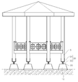
도 1은 본 발명에 따른 일실시예가 적용된 목조 건축물의 전체설치상태를 나타내는 정면도.
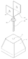
도 2는 본 발명에 따른 일실시예를 나타내는 분리사시도.
도 3은 본 발명에 따른 일실시예를 나타내는 정면도.
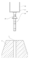
도 4는 본 발명에 따른 일실시예에서 너트체결부의 제1실시예를 나타내는 분리단면도.
도 5는 본 발명에 따른 일실시예에서 너트체결부의 제2실시예를 나타내는 분리단면도.
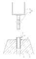
도 6은 본 발명에 따른 일실시예에서 너트체결부의 제3실시예를 나타내는 분리단면도.
도 7은 본 발명에 따른 일실시예에서 너트체결부의 제4실시예를 나타내는 분리단면도.
도 8은 본 발명에 따른 다른 실시예를 나타내는 단면도.BRIEF DESCRIPTION OF THE DRAWINGS FIG. 1 is a front view showing a whole installation state of a wooden building to which an embodiment according to the present invention is applied; FIG.
2 is an exploded perspective view showing an embodiment according to the present invention;
3 is a front view showing an embodiment according to the present invention;
4 is an exploded cross-sectional view of a first embodiment of a nut fastener in an embodiment according to the present invention;
FIG. 5 is an exploded cross-sectional view of a second embodiment of a nut tightening part in an embodiment according to the present invention; FIG.
FIG. 6 is an exploded cross-sectional view showing a third embodiment of the nut fastening part in the embodiment according to the present invention; FIG.
FIG. 7 is an exploded cross-sectional view showing a fourth embodiment of the nut fastening part in the embodiment according to the present invention; FIG.
8 is a cross-sectional view showing another embodiment according to the present invention;
본 발명은 지면에 설치되어 목조 건축물의 기둥 하단부를 지지 고정하는 목조 건축물 기둥 연결구조에 있어서, 지면에 하부가 부분적으로 매립 설치되고 상면에 상하 수직방향으로 관통된 관통공을 형성하는 기초PC블록과; 상기 기초PC블록의 관통공 상단에 대응하여 설치되고 상기 관통공에 연통하여 체결공이 형성되는 너트체결부와; 상부에 상기 기둥의 하단부를 지지토록 연결 고정하는 연결브라켓을 구비하고, 하부에 상하 수직방향으로 연장 형성되어 상기 관통공 내에 유입되되 상기 너트체결부에 나사 결합하여 상기 연결브라켓의 높이를 조절가능하게 형성된 유동체결단을 구비하는 철물브라켓부;를 포함하는 목조 건축물 높이 조절형 기둥 연결구조를 기술구성의 특징으로 한다.The present invention relates to a wooden building column connecting structure installed on a ground to support a lower end of a column of a wooden building, comprising: a basic PC block forming a through hole penetrating in a vertical direction on a top surface thereof, ; A nut fastening portion provided corresponding to the through hole top of the base PC block and formed with a fastening hole communicating with the through hole; And a connecting bracket for connecting and fixing the lower end portion of the column to the upper portion thereof. The connecting bracket is vertically extended in the lower portion and is introduced into the through hole, and is screwed to the nut fastening portion, And a metal bracket portion having a formed fluid body formed thereon, and a height adjustment type column connection structure of the wooden building.
다음으로 본 발명에 따른 목조 건축물 높이 조절형 기둥 연결구조의 바람직한 실시예를 도면을 참조하여 상세하게 설명한다.DETAILED DESCRIPTION OF THE PREFERRED EMBODIMENTS A preferred embodiment of a height-adjustable column connecting structure according to the present invention will now be described in detail with reference to the drawings.
먼저 본 발명에 따른 목조 건축물 높이 조절형 기둥 연결구조의 일실시예는 도 1 내지 도 3에 나타낸 바와 같이, 지면에 설치되어 목조 건축물의 기둥 하단부를 지지 고정하는 목조 건축물 기둥 연결구조에 있어서, 기초PC블록(10)과, 너트체결부(20)와, 철물브라켓부(30)를 포함하여 이루어진다.As shown in FIGS. 1 to 3, a wooden structure connecting structure of a height of a wooden building according to the present invention is a structure for connecting a wooden structure to a column, A
상기 기초PC블록(10)은 콘크리트를 사용하여 블록형상으로 제작된 프리캐스트 콘크리트(precast concrete) 형태를 이루므로, 시공현장에서의 원활한 시공을 도모할 수 있게 형성한다.Since the
상기 기초PC블록(10)의 경우, 도 2 및 도 3에서는 상부에 비해 하부의 단면적을 크게 형성하여 외측으로 하향경사진 측면을 갖는 사다리꼴 단면형상으로 형성하였지만, 본 발명에서의 기초PC블록(10)에 대한 형상을 이에 한정하는 것은 아니며, 상/하부의 단면적이 동일한 단면형상(예를 들면, 정사각형 또는 직사각형 등)으로 형성하는 것이 가능하고, 상면이 원형의 단면형상 및 다각형(예를 들면, 삼각형, 사각형, 육각형 등)으로 형성하는 것도 가능하다.2 and 3, the
상기 기초PC블록(10)은 시공현장의 지면에 하부가 부분적으로 매립 설치된다. 즉 상기 기초PC블록(10)의 하부는 지중에 매립하여 고정 설치하되 상부는 지상을 향해 돌출된 구조를 이루도록 형성한다.In the
상기 기초PC블록(10)에는 상면에 상하 수직방향으로 관통된 관통공(11)을 형성하여 상기 철물브라켓부(30)가 유입가능한 수용공간을 구비한다.The
상기에서 관통공(11)은 상기 기초PC블록(10)의 상하 높이영역의 전체에 걸쳐 수직방향으로 완전히 관통된 구조로 형성하는 것도 가능하고, 상기 관통공(11)이 상기 기초PC블록(10)의 상면에 소정의 깊이로만 관통된 구조로 형성하는 것도 가능하다.The through
상기 너트체결부(20)는 상기 기초PC블록(10) 상에 상기 철물브라켓부(30)를 설치가능하게 고정하는 기능을 수행한다.The nut fastening
상기 너트체결부(20)는 도 2 및 도 3에 나타낸 바와 같이, 상기 기초PC블록(10)의 관통공(11) 상단에 대응하여 설치되고, 상기 관통공(11)에 연통하는 체결공(21)을 구비토록 형성한다. 즉 상기 너트체결부(20)는 상기 기초PC블록(10)의 관통공(11)을 향해 유입되는 상기 철물브라켓부(30)에 대해 상기 체결공(21)에서 연결결합하도록 구성한다.2 and 3, the
상기 체결공(21)에는 상기 철물브라켓부(30)에 나사 결합가능하게 암나사를 형성한다.The fastening hole (21) is formed with a female screw so as to be screwable with the metal bracket part (30).
상기 너트체결부(20)는 상기 기초PC블록(10)을 기준으로 분리가능한 구조를 갖는 분리형으로 구성하는 것도 가능하고, 상기 기초PC블록(10) 상에 일체형으로 구성하는 것도 가능하다.The
상기 너트체결부(20)의 제1실시예는 도 4에 나타낸 바와 같이, 상기 기초PC블록(10)과는 구분하여 분리된 구조로서, 상기 기초PC블록(10)으로부터 분리가능한 분리형으로 이루어진다.As shown in FIG. 4, the first embodiment of the
상기 너트체결부(20)는 상기 철물브라켓부(30) 상에 일체로 구성한다. 즉 상기 철물브라켓부(30) 상에 나사 결합한 상태로 일체를 이루도록 구성하여 상기 기초PC블록(10)의 관통공(11) 상단에 대응하여 거치가능한 구조를 이루고, 상기 철물브라켓부(30)와 함께 상기 기초PC블록(10)으로부터 분리가능하게 구성한다.The nut fastening part (20) is integrally formed on the metal bracket part (30). The
상기한 제1실시예와 같이 너트체결부(20)를 구성하면, 기초PC블록(10)과 분리된 구조로부터 매우 간편하게 제품을 제작생산하는 것이 가능하다.It is possible to manufacture and produce a very simple product from the structure separated from the
상기 너트체결부(20)의 제2실시예는 도 5에 나타낸 바와 같이, 상기 기초PC블록(10)의 관통공(11) 상단에 대응하여 상기 기초PC블록(10) 상에 고정 설치되는 일체형으로 이루어진다.As shown in FIG. 5, the second embodiment of the
상기 너트체결부(20)는 상기 기초PC블록(10) 상에 고정형 또는 회전형의 구조를 이루도록 구성하는 것이 가능하다. 즉 상기 너트체결부(20)는 상기 기초PC블록(10) 상에 단순히 고정 설치되어 상기 철물브라켓부(30)의 회전에 의해서만 상호 결합이 이뤄질 수 있게 고정형으로 구성하는 것이 가능하고, 상기 너트체결부(20)는 도 5에 나타낸 바처럼 상기 기초PC블록(10) 상에 회전가능하게 설치하여 상기 철물브라켓부(30) 또는 상기 너트체결부(20)의 회전에 의한 상호 결합이 이뤄질 수 있게 회전형으로 구성하는 것도 가능하다.The
상기에서 회전형의 너트체결부(20)는 도 5에 나타낸 바와 같이, 상기 기초PC블록(10) 상에 설치되며 상부에 연결단(23)을 구비하는 고정플랜지(20a)와, 상기 고정플랜지(20a) 상에 회전가능하게 설치되고 상기 철물브라켓부(30)의 유동체결단(33)이 나사 결합가능하게 구비되는 회전너트부재(20b)로 구성한다. 즉 상기 고정플랜지(20a) 상에 회전가능하게 결합된 상기 회전너트부재(20b)를 회전조작하여 상기 철물브라켓부(30)를 결합하는 것이 가능하다.5, the rotatable
상기한 제1실시예와 같이 너트체결부(20)를 구성하면, 기초PC블록(10) 상에 철물브라켓부(30)의 체결작업이 용이하여 작업의 편의성을 도모하는 것이 가능하다.The
또한 상기 너트체결부(20)에는 도 6 및 도 7에 나타낸 바와 같이, 하측 수직방향으로 연장 형성되되 상기 체결공(21)의 체결구간을 연장하도록 형성되는 연장체결단부(25)를 더 포함하여 구성하는 것도 가능하다.Further, as shown in FIGS. 6 and 7, the
상기 연장체결단부(25)를 구비한 상기 너트체결부(20)에 있어서도 상기 기초PC블록(10)을 기준으로 분리형 또는 일체형으로 구성하는 것이 가능하다.The
상기 너트체결부(20)의 제3실시예는 도 6에 나타낸 바와 같이, 상기 기초PC블록(10)의 관통공(11) 내에 끼움 결합가능한 분리형으로 구성한다. 즉 상기 연장체결단부(25)가 형성된 상기 너트체결부(20)가 상기 기초PC블록(10)으로부터 분리되되 상기 철물브라켓부(30) 상에 일체로 구성하여 상기 너트체결부(20)의 연장체결단부(25)가 상기 기초PC블록(10)의 관통공(11) 내에 대응하여 끼움 결합가능한 구조를 이룬다.As shown in Fig. 6, the third embodiment of the
상기 너트체결부(20)의 제4실시예는 도 7에 나타낸 바와 같이, 상기 기초PC블록(10)의 관통공(11) 상에 인서트 성형되는 일체형으로 구성한다. 즉 상기 너트체결부(20)의 연장체결단부(25) 부분이 상기 기초PC블록(10)의 관통공(11) 상에 일체로 인서트 성형한 구조를 이룬다.As shown in Fig. 7, the fourth embodiment of the
상기와 같이 너트체결부(20)에 연장체결단부(25)를 구성하게 되면, 너트체결부(20)의 체결가능구간을 연장형성하므로 체결영역에 걸리는 하중을 고르게 분산시켜 건축물의 안정적인 지지효율을 도모함과 동시에 구성 간의 체결구조를 보강하여 구성의 파손현상을 방지하는 것이 가능하다.As described above, when the extended
상기 철물브라켓부(30)는 상기 기초PC블록(10)의 상부에 위치하여 기둥의 하단부를 지지 고정하는 기능을 수행한다.The
상기 철물브라켓부(30)는 도 2 및 도 3에 나타낸 바와 같이, 상부에서 기둥(5)의 하단부를 지지토록 연결고정하는 연결브라켓(31)과, 상기 너트체결부(20) 상에 나사 결합하는 유동체결단(33)을 구비토록 구성한다.As shown in FIGS. 2 and 3, the
상기 연결브라켓(31)은 목조 건축물의 기둥(5)을 받쳐 지지할 수 있게 평탄한 평면을 형성하되 기둥(5)의 측면을 부분적으로 접촉 지지토록 양쪽 측단에 측벽을 형성한다.The
상기 연결브라켓(31)의 측벽에는 기둥을 고정 결합할 수 있는 체결부재(나사 또는 볼트 등)가 측 방향으로 진입할 수 있게 좌우로 관통된 결합공(32)을 형성한다.A
상기 유동체결단(33)은 상기 연결브라켓(31)의 하부에 상하 수직방향으로 연장 형성된다. 즉 상기 유동체결단(33)은 상기 기초PC블록(10)의 관통공(11) 내에 유입되어 상하로 유동가능한 구조로 연장 형성된다.The
상기 유동체결단(33)은 상기 기초PC블록(10)의 관통공(11)을 향해 유입됨과 동시에 상기 너트체결부(20)에 나사 결합하여 고정된다.The
상기 철물브라켓부(30)는 상기 너트체결부(20) 상에 체결된 상기 유동체결단(33)의 결합위치에 따라 상기 기둥(5)을 지지하는 상기 연결브라켓(31)의 높이를 조절가능하게 형성된다.The
예를 들면, 상기 너트체결부(20) 또는 상기 철물브라켓부(30)를 회전시켜 기둥(5)의 높이를 조절하되, 상기 너트체결부(20)를 시계방향으로 회전시키거나 상기 철물브라켓부(30)를 반시계방향으로 회전시키면 상기 철물브라켓부(30)가 상향이동되어 기둥(5)의 지지높이를 높이게 되고, 반면에 상기 너트체결부(20)를 반시계방향으로 회전시키거나 상기 철물브라켓부(30)를 시계방향으로 회전시키면 상기 철물브라켓부(30)가 하향이동되어 기둥(5)의 지지높이를 낮추게 된다.For example, the height of the
즉 상기와 같이 구성되는 본 발명에 따른 목조 건축물 높이 조절형 기둥 연결구조에 의하면, 목재기둥을 노출상태로 지지고정하되 개개의 목재기둥마다 설치높이를 탄력적으로 조절하여 시공하므로, 목재기둥의 변경을 방지하여 설치수명을 연장함과 동시에 건축물의 내구성을 향상시키고, 목재기둥의 시공작업이 매우 용이하며 목재기둥에 따른 전체적인 건축물의 균형을 맞춰 시공안정성 및 시공품질을 대폭 향상시키는 것이 가능하다.In other words, according to the wooden structure height-adjustable column connection structure of the present invention constructed as described above, since the wooden columns are exposed and fixed, the installation height is adjusted flexibly for each wooden column, It is possible to improve the durability of the building and the construction work of the wooden pillar is very easy and the balance of the whole building according to the wooden pillar can be balanced to greatly improve the stability of the construction and the quality of the construction.
그리고 본 발명에 따른 목조 건축물 높이 조절형 기둥 연결구조의 다른 실시예는 도 8에 나타낸 바와 같이, 상기 철물브라켓부(30)와 구분하여 상기 기초PC블록(10) 상부에 상측 수직방향으로 돌출 형성되고 상기 철물브라켓부(30)의 연결브라켓(31) 하면에 접촉지지하는 서브지지수단(40)을 더 포함하여 이루어진다.8, the upper part of the
상기 서브지지수단(40)은 상기 철물브라켓부(30)의 연결브라켓(31) 하면을 접촉지지하되 상기 연결브라켓(31)의 높이에 따라 상하 수직방향으로 유동가능하게 형성된다.The sub support means 40 supports the lower surface of the
상기 서브지지수단(40)은 상기 기초PC블록(10)의 상면에 내측으로 매립 설치되는 유동안내부재(41)와, 상기 유동안내부재(41) 상에 결합 설치되되 상기 연결브라켓(31)을 향해 상측으로 돌출 형성되는 받침부재(43)와, 상기 받침부재(43)의 하부를 지지토록 상기 유동안내부재(41) 내에 구비되는 탄성부재(45)로 구성한다.The sub support means 40 includes a
상기 받침부재(43)는 상하 수직방향으로 연장형성하되 상단부의 면적을 크게 형성하므로, 상기 연결브라켓(31)을 향해 지지효율을 향상시킬 수 있게 구성하는 것이 바람직하다.The
즉 상기한 다른 실시예와 같이 본 발명을 구성하면, 목재기둥이 결합된 철물브라켓부의 구성을 접촉지지하므로, 건축물을 보다 안정적으로 지지하면서 건축물의 지지하중을 보다 고르게 분산시켜 건축물을 수명을 연장하는 것이 가능하다.That is, according to the present invention as in the above-mentioned other embodiments, since the structure of the bracket part of the metal bracket combined with the wooden column is contacted and supported, the supporting load of the building is more evenly distributed while supporting the building more stably, It is possible.
상기한 다른 실시예에 있어서도 상기한 구성 이외에는 상기한 일실시예와 마찬가지의 구성으로 실시하는 것이 가능하므로 상세한 설명은 생략한다.In the other embodiments described above, the same configuration as that of the above-described embodiment can be employed, so that detailed description is omitted.
상기에서는 본 발명에 따른 목조 건축물 높이 조절형 기둥 연결구조의 바람직한 실시예에 대하여 설명하였지만, 본 발명은 이에 한정되는 것이 아니고 특허청구범위와 발명의 상세한 설명 및 첨부한 도면의 범위 안에서 여러가지로 변형하여 실시하는 것이 가능하고, 이 또한 본 발명의 범위에 속한다.
Although the present invention has been described with respect to a preferred embodiment of a height-adjustable column connecting structure according to the present invention, the present invention is not limited to this, and various modifications and changes may be made within the scope of the claims, And this is also within the scope of the present invention.
10 : 기초PC블록
11 : 관통공
20 : 너트체결부
21 : 체결공
20a : 고정플랜지
20b : 회전너트부재
23 : 연결단
25 : 연장체결단부
30 : 철물브라켓부
31 : 연결브라켓
32 : 결합공
33 : 유동체결단
40 : 서브지지수단
41 : 유동안내부재
43 : 받침부재
45 : 탄성부재10: Basic PC block 11: Through hole
20: nut fastening part 21: fastening hole
20a: Fixing
23: connection end 25: extended end
30: Hardware bracket part 31: Connection bracket
32: Coupling hole 33: Fluid determination
40: Sub-support means 41: Flow guide member
43: support member 45: elastic member
Claims (8)
지면에 하부가 부분적으로 매립 설치되고 상면에 상하 수직방향으로 관통된 관통공을 형성하는 기초PC블록과;
상기 기초PC블록의 관통공 상단에 대응하여 설치되고 상기 관통공에 연통하여 체결공이 형성되는 너트체결부와;
상부에 상기 기둥의 하단부를 지지토록 연결 고정하는 연결브라켓을 구비하고, 하부에 상하 수직방향으로 연장 형성되어 상기 관통공 내에 유입되되 상기 너트체결부에 나사 결합하여 상기 연결브라켓의 높이를 조절가능하게 형성된 유동체결단을 구비하는 철물브라켓부;를 포함하여 이루어지는 목조 건축물 높이 조절형 기둥 연결구조.
A wooden building post connection structure installed on a ground to support and fix a lower end of a column of a wooden building,
A base PC block partially embedded with a lower portion on the ground and forming a through hole penetrating the upper surface in a vertical direction;
A nut fastening portion provided corresponding to the through hole top of the base PC block and formed with a fastening hole communicating with the through hole;
And a connecting bracket for connecting and fixing the lower end portion of the column to the upper portion thereof. The connecting bracket is vertically extended in the lower portion and is introduced into the through hole, and is screwed to the nut fastening portion, And a metal bracket portion having a formed fluid body formed thereon.
상기 너트체결부는, 상기 철물브라켓부의 유동체결단 상에 나사 결합한 상태로 일체로 구성하여 상기 기초PC블록으로부터 분리가능한 분리형으로 이루어지는 목조 건축물 높이 조절형 기둥 연결구조.
The method according to claim 1,
Wherein the nut fastening portion is detachable from the base PC block integrally formed in a state of being screwed on the fluidic body of the metal bracket portion.
상기 너트체결부는, 상기 기초PC블록 상의 고정 설치되는 일체형으로 이루어지는 목조 건축물 높이 조절형 기둥 연결구조.
The method according to claim 1,
Wherein the nut fastening portion is integrally formed with the base PC block and is fixedly installed on the base PC block.
상기 너트체결부는, 상기 기초PC블록 상에 설치되며 상부에 연결단을 구비하는 고정플랜지와, 상기 고정플랜지 상에 회전가능하게 설치되고 상기 철물브라켓부의 유동체결단이 나사 결합가능하게 구비되는 회전너트부재를 포함하여 이루어지는 목조 건축물 높이 조절형 기둥 연결구조.
The method of claim 3,
Wherein the nut fastening portion includes a fixing flange provided on the base PC block and having a connection end on an upper portion thereof and a rotation nut member provided rotatably on the fixing flange, And a height-adjustable column connection structure.
상기 너트체결부에는 하측 수직방향으로 연장 형성되되 상기 체결공의 체결구간을 연장하도록 형성되는 연장체결단부를 더 포함하여 이루어지는 목조 건축물 높이 조절형 기둥 연결구조.
The method according to claim 1,
Wherein the nut fastening portion further includes an extension fastening end portion extending in a lower vertical direction and extending to a fastening portion of the fastening hole.
상기 너트체결부는 상기 기초PC블록의 관통공 내에 끼움 결합가능한 분리형 또는 상기 기초PC블록의 관통공 상에 인서트 성형되는 일체형으로 이루어지는 목조 건축물 높이 조절형 기둥 연결구조.
The method according to claim 1,
Wherein the nut fastening portion is integrally formed with a detachable type insertable into a through hole of the base PC block or insert formed on a through hole of the base PC block.
상기 기초PC블록 상부에 상측 수직방향으로 돌출 형성되고 상기 철물브라켓부의 연결브라켓 하면에 접촉지지하되 상기 연결브라켓의 높이에 따라 상하 수직방향으로 유동가능하게 형성되는 서브지지수단을 더 포함하여 이루어지는 목조 건축물 높이 조절형 기둥 연결구조.
The method according to any one of claims 1 to 6,
Further comprising a sub support means protruding upward in the upper side of the basic PC block and supported by the lower surface of the connection bracket of the hardware bracket portion so as to be vertically movable in accordance with the height of the connection bracket, Height adjustable column connection structure.
상기 서브지지수단은, 상기 기초PC블록의 상면에 내측으로 매립 설치되는 유동안내부재와, 상기 유동안내부재 상에 결합 설치되되 상기 연결브라켓을 향해 상측으로 돌출 형성되는 받침부재와, 상기 받침부재의 하부를 지지토록 상기 유동안내부재 내에 구비되는 탄성부재를 포함하여 이루어지는 목조 건축물 높이 조절형 기둥 연결구조.
The method of claim 7,
The sub support means includes a flow guide member embedded inwardly on the upper surface of the base PC block, a support member provided on the flow guide member and protruding upward toward the connection bracket, And an elastic member provided in the flow guide member so as to support a lower portion thereof.
Priority Applications (1)
| Application Number | Priority Date | Filing Date | Title |
|---|---|---|---|
| KR1020150187182A KR101821230B1 (en) | 2015-12-28 | 2015-12-28 | Height Control Type Pillar Connecting Structure for Wooden Building |
Applications Claiming Priority (1)
| Application Number | Priority Date | Filing Date | Title |
|---|---|---|---|
| KR1020150187182A KR101821230B1 (en) | 2015-12-28 | 2015-12-28 | Height Control Type Pillar Connecting Structure for Wooden Building |
Publications (2)
| Publication Number | Publication Date |
|---|---|
| KR20170077364A true KR20170077364A (en) | 2017-07-06 |
| KR101821230B1 KR101821230B1 (en) | 2018-01-24 |
Family
ID=59354178
Family Applications (1)
| Application Number | Title | Priority Date | Filing Date |
|---|---|---|---|
| KR1020150187182A Active KR101821230B1 (en) | 2015-12-28 | 2015-12-28 | Height Control Type Pillar Connecting Structure for Wooden Building |
Country Status (1)
| Country | Link |
|---|---|
| KR (1) | KR101821230B1 (en) |
Cited By (1)
| Publication number | Priority date | Publication date | Assignee | Title |
|---|---|---|---|---|
| CN107780672A (en) * | 2017-09-18 | 2018-03-09 | 湖北源盛钢构有限公司 | Assembled architecture |
Families Citing this family (1)
| Publication number | Priority date | Publication date | Assignee | Title |
|---|---|---|---|---|
| KR102503438B1 (en) | 2022-09-08 | 2023-02-24 | 유한회사 덕성 | Pergolas with tilt compensation function |
Family Cites Families (3)
| Publication number | Priority date | Publication date | Assignee | Title |
|---|---|---|---|---|
| JP3356207B2 (en) * | 1998-12-10 | 2002-12-16 | 株式会社トピックス | Earthquake-resistant connecting material for wooden structures |
| KR200343286Y1 (en) * | 2003-11-18 | 2004-03-02 | 윤태흥 | Pedestal having hight control function for moving-style building |
| JP2006045811A (en) * | 2004-08-02 | 2006-02-16 | Otis:Kk | Wooden post body |
-
2015
- 2015-12-28 KR KR1020150187182A patent/KR101821230B1/en active Active
Cited By (1)
| Publication number | Priority date | Publication date | Assignee | Title |
|---|---|---|---|---|
| CN107780672A (en) * | 2017-09-18 | 2018-03-09 | 湖北源盛钢构有限公司 | Assembled architecture |
Also Published As
| Publication number | Publication date |
|---|---|
| KR101821230B1 (en) | 2018-01-24 |
Similar Documents
| Publication | Publication Date | Title |
|---|---|---|
| US8240097B2 (en) | Wood post anchoring base | |
| AU2019100993A4 (en) | Height-Adjustable Jack and Vertical Modular Component Support using the same | |
| CA2966091A1 (en) | Stabilizing systems for deck pedestals | |
| AU2019236669A1 (en) | Clamps for panel-type fences | |
| KR100998734B1 (en) | Wall panel horizontal retaining member of prefabricated bathroom and its installation structure | |
| KR102097339B1 (en) | Deck supporting system | |
| KR101499111B1 (en) | Hybrid Foundation For Water Tank | |
| KR101821230B1 (en) | Height Control Type Pillar Connecting Structure for Wooden Building | |
| KR200462716Y1 (en) | Curbstone constructing equipment | |
| US11293189B2 (en) | Flooring system for use in a sloped floor | |
| US20070006540A1 (en) | Apparatus and method for supporting a modular building | |
| KR102004321B1 (en) | Foundation pad for water tank which is easy to control the height and level | |
| KR101235244B1 (en) | Height adjustable building blocks | |
| CN114197806A (en) | Assembly type ground leveling structure | |
| KR101439789B1 (en) | A post foundation device | |
| CN216766640U (en) | Assembly type ground leveling structure | |
| KR100493695B1 (en) | A flat-stone supporting flame in a bottom fountain and adjusting method thereof | |
| KR200415831Y1 (en) | Height adjustment of lightweight panel for partition | |
| KR20130007194U (en) | Combination structure of a grating and kickplate | |
| EP2172602A1 (en) | Supporting structure for an access floor | |
| CN116733190B (en) | A modular prefabricated ground structure designed to prevent deformation and settlement | |
| KR102716729B1 (en) | Raised floor | |
| KR100390059B1 (en) | Level for a plaster | |
| KR20160011982A (en) | Horizontal control device for transportable building | |
| KR200312035Y1 (en) | A flat-stone supporting flame in a bottom fountain |
Legal Events
| Date | Code | Title | Description |
|---|---|---|---|
| A201 | Request for examination | ||
| PA0109 | Patent application |
Patent event code: PA01091R01D Comment text: Patent Application Patent event date: 20151228 |
|
| PA0201 | Request for examination | ||
| E902 | Notification of reason for refusal | ||
| PE0902 | Notice of grounds for rejection |
Comment text: Notification of reason for refusal Patent event date: 20170522 Patent event code: PE09021S01D |
|
| PG1501 | Laying open of application | ||
| E701 | Decision to grant or registration of patent right | ||
| PE0701 | Decision of registration |
Patent event code: PE07011S01D Comment text: Decision to Grant Registration Patent event date: 20171127 |
|
| GRNT | Written decision to grant | ||
| PR0701 | Registration of establishment |
Comment text: Registration of Establishment Patent event date: 20180117 Patent event code: PR07011E01D |
|
| PR1002 | Payment of registration fee |
Payment date: 20180118 End annual number: 3 Start annual number: 1 |
|
| PG1601 | Publication of registration | ||
| PR1001 | Payment of annual fee |
Payment date: 20210113 Start annual number: 4 End annual number: 4 |
|
| PR1001 | Payment of annual fee |
Payment date: 20220112 Start annual number: 5 End annual number: 5 |
|
| PR1001 | Payment of annual fee |
Payment date: 20221222 Start annual number: 6 End annual number: 6 |
|
| PR1001 | Payment of annual fee |
Payment date: 20250109 Start annual number: 8 End annual number: 8 |