KR20170077751A - A Graphin Filter System for Dishwater and Wastewater - Google Patents
A Graphin Filter System for Dishwater and Wastewater Download PDFInfo
- Publication number
- KR20170077751A KR20170077751A KR1020150191913A KR20150191913A KR20170077751A KR 20170077751 A KR20170077751 A KR 20170077751A KR 1020150191913 A KR1020150191913 A KR 1020150191913A KR 20150191913 A KR20150191913 A KR 20150191913A KR 20170077751 A KR20170077751 A KR 20170077751A
- Authority
- KR
- South Korea
- Prior art keywords
- cyclone body
- graphene filter
- water
- pipe
- installing
- Prior art date
- Legal status (The legal status is an assumption and is not a legal conclusion. Google has not performed a legal analysis and makes no representation as to the accuracy of the status listed.)
- Ceased
Links
- 239000002351 wastewater Substances 0.000 title claims abstract description 23
- XLYOFNOQVPJJNP-UHFFFAOYSA-N water Substances O XLYOFNOQVPJJNP-UHFFFAOYSA-N 0.000 claims abstract description 48
- 238000004064 recycling Methods 0.000 claims abstract description 7
- OKTJSMMVPCPJKN-UHFFFAOYSA-N Carbon Chemical compound [C] OKTJSMMVPCPJKN-UHFFFAOYSA-N 0.000 claims description 32
- 229910021389 graphene Inorganic materials 0.000 claims description 31
- 238000004140 cleaning Methods 0.000 claims description 13
- 238000009423 ventilation Methods 0.000 claims description 3
- 238000000926 separation method Methods 0.000 claims description 2
- 241000894006 Bacteria Species 0.000 claims 1
- QVGXLLKOCUKJST-UHFFFAOYSA-N atomic oxygen Chemical compound [O] QVGXLLKOCUKJST-UHFFFAOYSA-N 0.000 claims 1
- 239000003673 groundwater Substances 0.000 claims 1
- 229910052760 oxygen Inorganic materials 0.000 claims 1
- 239000001301 oxygen Substances 0.000 claims 1
- 239000010865 sewage Substances 0.000 abstract description 9
- 238000000034 method Methods 0.000 abstract description 6
- 238000003911 water pollution Methods 0.000 abstract description 5
- 238000004519 manufacturing process Methods 0.000 abstract description 3
- 239000003599 detergent Substances 0.000 abstract description 2
- 239000010840 domestic wastewater Substances 0.000 abstract 1
- XEEYBQQBJWHFJM-UHFFFAOYSA-N Iron Chemical compound [Fe] XEEYBQQBJWHFJM-UHFFFAOYSA-N 0.000 description 12
- 229910052742 iron Inorganic materials 0.000 description 6
- 239000007788 liquid Substances 0.000 description 3
- CWYNVVGOOAEACU-UHFFFAOYSA-N Fe2+ Chemical compound [Fe+2] CWYNVVGOOAEACU-UHFFFAOYSA-N 0.000 description 1
- CBENFWSGALASAD-UHFFFAOYSA-N Ozone Chemical compound [O-][O+]=O CBENFWSGALASAD-UHFFFAOYSA-N 0.000 description 1
- 230000000903 blocking effect Effects 0.000 description 1
- 238000010276 construction Methods 0.000 description 1
- 238000010586 diagram Methods 0.000 description 1
- 230000000694 effects Effects 0.000 description 1
- 238000001914 filtration Methods 0.000 description 1
- 239000007789 gas Substances 0.000 description 1
- 238000010438 heat treatment Methods 0.000 description 1
- 125000004435 hydrogen atom Chemical group [H]* 0.000 description 1
- 239000008235 industrial water Substances 0.000 description 1
- 238000009434 installation Methods 0.000 description 1
- 239000000463 material Substances 0.000 description 1
- 239000012528 membrane Substances 0.000 description 1
- 239000002245 particle Substances 0.000 description 1
- 238000000746 purification Methods 0.000 description 1
- 238000001223 reverse osmosis Methods 0.000 description 1
- 239000013535 sea water Substances 0.000 description 1
- 229910001220 stainless steel Inorganic materials 0.000 description 1
- 239000010935 stainless steel Substances 0.000 description 1
- 210000002700 urine Anatomy 0.000 description 1
- 238000004065 wastewater treatment Methods 0.000 description 1
Images

Classifications
-
- B—PERFORMING OPERATIONS; TRANSPORTING
- B01—PHYSICAL OR CHEMICAL PROCESSES OR APPARATUS IN GENERAL
- B01D—SEPARATION
- B01D35/00—Filtering devices having features not specifically covered by groups B01D24/00 - B01D33/00, or for applications not specifically covered by groups B01D24/00 - B01D33/00; Auxiliary devices for filtration; Filter housing constructions
- B01D35/06—Filters making use of electricity or magnetism
-
- B—PERFORMING OPERATIONS; TRANSPORTING
- B01—PHYSICAL OR CHEMICAL PROCESSES OR APPARATUS IN GENERAL
- B01D—SEPARATION
- B01D35/00—Filtering devices having features not specifically covered by groups B01D24/00 - B01D33/00, or for applications not specifically covered by groups B01D24/00 - B01D33/00; Auxiliary devices for filtration; Filter housing constructions
- B01D35/16—Cleaning-out devices, e.g. for removing the cake from the filter casing or for evacuating the last remnants of liquid
-
- B—PERFORMING OPERATIONS; TRANSPORTING
- B01—PHYSICAL OR CHEMICAL PROCESSES OR APPARATUS IN GENERAL
- B01D—SEPARATION
- B01D39/00—Filtering material for liquid or gaseous fluids
- B01D39/14—Other self-supporting filtering material ; Other filtering material
- B01D39/20—Other self-supporting filtering material ; Other filtering material of inorganic material, e.g. asbestos paper, metallic filtering material of non-woven wires
- B01D39/2055—Carbonaceous material
-
- B—PERFORMING OPERATIONS; TRANSPORTING
- B04—CENTRIFUGAL APPARATUS OR MACHINES FOR CARRYING-OUT PHYSICAL OR CHEMICAL PROCESSES
- B04C—APPARATUS USING FREE VORTEX FLOW, e.g. CYCLONES
- B04C9/00—Combinations with other devices, e.g. fans, expansion chambers, diffusors, water locks
-
- C—CHEMISTRY; METALLURGY
- C02—TREATMENT OF WATER, WASTE WATER, SEWAGE, OR SLUDGE
- C02F—TREATMENT OF WATER, WASTE WATER, SEWAGE, OR SLUDGE
- C02F1/00—Treatment of water, waste water, or sewage
- C02F1/02—Treatment of water, waste water, or sewage by heating
- C02F1/04—Treatment of water, waste water, or sewage by heating by distillation or evaporation
-
- C—CHEMISTRY; METALLURGY
- C02—TREATMENT OF WATER, WASTE WATER, SEWAGE, OR SLUDGE
- C02F—TREATMENT OF WATER, WASTE WATER, SEWAGE, OR SLUDGE
- C02F1/00—Treatment of water, waste water, or sewage
- C02F1/38—Treatment of water, waste water, or sewage by centrifugal separation
-
- C—CHEMISTRY; METALLURGY
- C02—TREATMENT OF WATER, WASTE WATER, SEWAGE, OR SLUDGE
- C02F—TREATMENT OF WATER, WASTE WATER, SEWAGE, OR SLUDGE
- C02F1/00—Treatment of water, waste water, or sewage
- C02F1/48—Treatment of water, waste water, or sewage with magnetic or electric fields
- C02F1/484—Treatment of water, waste water, or sewage with magnetic or electric fields using electromagnets
-
- C—CHEMISTRY; METALLURGY
- C02—TREATMENT OF WATER, WASTE WATER, SEWAGE, OR SLUDGE
- C02F—TREATMENT OF WATER, WASTE WATER, SEWAGE, OR SLUDGE
- C02F2103/00—Nature of the water, waste water, sewage or sludge to be treated
- C02F2103/007—Contaminated open waterways, rivers, lakes or ponds
-
- C—CHEMISTRY; METALLURGY
- C02—TREATMENT OF WATER, WASTE WATER, SEWAGE, OR SLUDGE
- C02F—TREATMENT OF WATER, WASTE WATER, SEWAGE, OR SLUDGE
- C02F2103/00—Nature of the water, waste water, sewage or sludge to be treated
- C02F2103/06—Contaminated groundwater or leachate
Landscapes
- Chemical & Material Sciences (AREA)
- Engineering & Computer Science (AREA)
- Life Sciences & Earth Sciences (AREA)
- Water Supply & Treatment (AREA)
- Chemical Kinetics & Catalysis (AREA)
- Hydrology & Water Resources (AREA)
- Environmental & Geological Engineering (AREA)
- Organic Chemistry (AREA)
- Electromagnetism (AREA)
- Physics & Mathematics (AREA)
- Analytical Chemistry (AREA)
- Mechanical Engineering (AREA)
- Geology (AREA)
- Cyclones (AREA)
Abstract
그래핀시트를 오, 폐수를 재활용하기위한 필터시스템에 관한 것으로 보다 상세하게는 생활오수나, 공장폐수에서 물을 분리하여 물을 재활용하기위한 필터시스템이다
가정에서 사용하는 주방세제와 세탁세제에 의해 생활오수가 발생하여 그래도 하천으로 방류됨으로서 수질오염이 발생하고, 또한 공장에서 제품의 생산을 위해서 발생되는 폐수를 정화하는데 막대한 비용이 발생한다.
따라서, 현재 생활오수에서 발생하는 수질오염이 심각한 상태이며, 물을 한번사용하고 버릴 수밖에 없으므로 물 부족현상이 세계적으로 큰 이슈가 되고 있다.
본 발명은 상기와 같은 문제를 해결하기위해서 안출된 것으로서, 가정이나 공장에서 발생하는 오수와 폐수에서 깨끗한 물을 분리하여 재활용 할 수 있으며, 필터를 교체하지 않고 철성분의 찌꺼기와 액체상태이며, 비철성분의 찌꺼기를 분리하여 필터링하여 포집하여 증발시키며, 남은 찌꺼기를 포집하여 수거하고, 물 자원의 재생도 할 수 있도록 구성하였으므로 반드시 필요한 발명이라 할 수 있다.More particularly, the present invention relates to a filter system for recycling wastewater by separating water from domestic wastewater or plant wastewater
The household sewage and kitchen detergent used in the household causes sewage to be discharged to the river, resulting in water pollution, and a great cost is incurred in purifying wastewater generated in the factory for product production.
As a result, water pollution from domestic sewage is severely polluted, and water shortage is inevitable. Therefore, water shortage is becoming a big issue in the world.
Disclosure of Invention Technical Problem [8] Accordingly, the present invention has been made to solve the above-mentioned problems, and it is an object of the present invention to provide a method of separating clean water from sewage and wastewater generated in a home or a factory, It is a necessary invention since it is constituted so as to separate and filter the residues of the components, to collect and evaporate them, to collect and collect the remaining residues, and to regenerate water resources.
Description
본 발명은 그래핀시트를 오, 폐수를 재활용하기위한 필터시스템에 관한 것으로 보다 상세하게는 생활오수나, 공장폐수에서 물을 분리하여 물을 재활용하기위한 필터시스템이다BACKGROUND OF THE INVENTION 1. Field of the Invention The present invention relates to a filter system for recycling wastewater into a graphene sheet and more particularly to a filter system for recycling water by separating water from domestic sewage or factory wastewater
가정에서 사용하는 주방세제와 세탁세제에 의해 생활오수가 발생하여 그래도 하천으로 방류됨으로서 수질오염이 발생하고, 또한 공장에서 제품의 생산을 위해서 발생되는 폐수를 정화하는데 막대한 비용이 발생한다.The household sewage and kitchen detergent used in the household causes sewage to be discharged to the river, resulting in water pollution, and a great cost is incurred in purifying wastewater generated in the factory for product production.
특히, 가정에서 발생되는 생활 오수를 각각의 가정에서 정화하는 것을, 화학적으로 처리는 하는 경우, 전문가의 도움 없이 수질정화를 목적으로 기계장치를 운행하는 것은 현실적으로 불가능하다.In particular, it is practically impossible to clean the domestic sewage generated in the home in each household, and if it is treated chemically, it is practically impossible to operate the machinery for purifying the water without the help of experts.
물론, 공장에서 전문가를 배치한 상태에서 수질정화시스템을 운영하여 폐수를 정화하는 것은 당연지사이나 막대한 비용이 발생하여 생산단가의 상승으로 이어진다.Of course, it is natural to clean the wastewater by operating a water quality purification system with a specialist in the factory, which can lead to an increase in production costs due to a great cost.
따라서, 현재 생활오수에서 발생하는 수질오염이 심각한 상태이며, 물을 한번사용하고 버릴 수밖에 없으므로 물 부족현상이 세계적으로 큰 이슈가 되고 있다.As a result, water pollution from domestic sewage is severely polluted, and water shortage is inevitable. Therefore, water shortage is becoming a big issue in the world.
본 발명은 상기와 같은 문제를 해결하기위해서 안출된 것으로서, 가정이나 공장에서 발생하는 오수와 폐수에서 깨끗한 물을 분리하여 재활용 할 수 있도록 하였다.Disclosure of Invention Technical Problem [8] The present invention has been made in order to solve the above problems, and it has been possible to separate and recycle clean water from wastewater and wastewater generated in homes and factories.
이때, 필터를 교체하지 않고 철성분의 찌꺼기와 액체상태이며, 비철성분의 찌꺼기를 분리하여 필터링하여 포집하여 증발시키며, 남은 찌꺼기를 포집하여 수거하고, 물 자원의 재생도 할 수 있도록 구성하였다.At this time, the filter is not replaced, and the residue of the iron component is in a liquid state. The non-iron component residue is separated, filtered, collected and evaporated, and the remaining residue is collected and recovered.
그레핀은 가스나 물 등을 통과시키지 않고, 수소원자만을 통과시키는 것으로 알려져 왔으나, 최근 그래핀의 구조를 변형시켜 물입자만을 통과시키는 기술이 개발되어, 바닷물을 담수하는 과정에서 그래핀 멤브레인 필터를 사용하여 깨끗한 물을 분리하는 기술들이 성공되고 있다.Recently, graphene has been known to pass only hydrogen atoms without passing gas or water. However, recently, a technique of passing only water particles by modifying the structure of graphene has been developed. In the process of desalinating seawater, a graphene membrane filter Techniques for using clean water for separation have been successful.
우선, 오수와 폐수의 배출관에서 유입되는 사이클론 본체 입구부에 전자석 부를 설치하였고, 그 전자석의 단부주위로 혼탁한물을 통과시키도록 하며, 사이클론 본체의 하부에 그래핀시트로서 만든 필터를 설치하였으며, 펌프로 흡입되는 공정에서 발생되는 물의 이동속도와 힘을 이용하여 수중에서 임펠러를 회전시켜 그 회전력으로 그래핀의 표면에 부착되는 비철 성분을 그래핀필터에서 분리되도록 하여 물이 그래핀필터를 통과하는 효율을 높여 준다.First, an electromagnet portion is provided at the inlet of the cyclone main body to be introduced from the discharge pipe of the wastewater and wastewater, a turbid material is passed around the end portion of the electromagnet, a filter made as a graphene sheet is installed at the lower portion of the cyclone body, The impeller is rotated in water using the moving speed and force of the water generated in the process of suction, and the non-iron component attached to the surface of the graphene is separated from the graphene filter by the rotational force, .
또한, 전자석에서 포집된 철성분의 찌꺼기는 오, 폐수가 발생하지 않는 시간에 전자석 부를 상부로 들어 물과 분리시킨 후 전원을 단락시켜 찌꺼기를 제거 분리 하며, 그래핀필터에서 포집된 액체 상태이며, 비철성분의 찌꺼기는 물이 하부로 전량 빠진 후, 히터로 가열하여 말린 후, 터보팬으로 흡입하여 포집부에 수거하여 버리고, 물은 재활용 할 수 있도록 하였다.In addition, the residues of the iron component collected in the electromagnet are separated by water from the upper portion of the electromagnet portion at a time when no wastewater is generated, and then the electric power is short-circuited to remove and remove the residue, The residue of non-ferrous components was removed from the lower part of the water, dried by heating with a heater, sucked into a turbo fan, collected in the collecting part, and water was recycled.
상기에서 기술한 바와 같이 본 발명의 오, 폐수의 재활용 그래핀 필터 시스템은 다음과 같은 효과를 발생시킨다.As described above, the recycling graphene filter system of waste water of the present invention produces the following effects.
1. 오, 폐수가 발생하지 않는다.1. Oh, there is no waste water.
2. 공장폐수 처리 가격이 저렴하다.2. Factory wastewater treatment price is low.
3. 물을 재활용 할 수 있다.3. Water can be recycled.
4. 수질오염이 발생하지 않는다.4. Water pollution does not occur.
따라서 , 본 발명은 반드시 필요한 발명이다.Therefore, the present invention is a necessary invention.
제1도 : 본 발명의 오, 폐수 재활용 그래핀 필터시스템의 공정도.
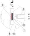
제2도 : 본 발명의 "가" - "가"선의 단면도.
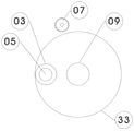
제3도 : 본 발명의 부분 확대도.
* 도면의 주요한 부호에 대한 설명
01) 전자밸브 03) 원형관 05) 액추에이터 07) 전자석
09) 배출관 11) 터보팬 13) 수위센서 15) 습도센서
17) 포집통 19) 포집자루 21) 물탱크 23) 전자밸브
25) 펌프 27) 수위센서 29) 물공급관 31) 히터
33) 사이클론 본체
77) 임펠러 88) 세척솔 99) 그래핀필터1 is a process diagram of an ozone / wastewater recycling graphene filter system of the present invention.
2 is a cross-sectional view of the "a" - "a" line of the present invention.
3 is a partially enlarged view of the present invention.
DESCRIPTION OF REFERENCE NUMERALS
01) Solenoid valve 03) Circular tube 05) Actuator 07) Electromagnet
09) Exhaust pipe 11) Turbo fan 13) Water level sensor 15) Humidity sensor
17) Collecting container 19) Collecting bag 21) Water tank 23) Solenoid valve
25) Pump 27) Water level sensor 29) Water supply pipe 31) Heater
33) Cyclone body
77) Impeller 88) Cleaning brush 99) Graphen filter
본 발명의 구성을 첨부도면 제1도에서 제3도까지의 제시된 도면에 의거하여 상세히 설명하면 다음과 같다.The construction of the present invention will be described in detail with reference to the drawings shown in FIGS. 1 to 3.
오, 폐수의 배출 관에 전자밸브(01)를 설치하고; 상기 전자밸브(01)의 다른 쪽 나사부와 사이클론 본체(33)의 입구부에 원형관(03)을 설치하고; 상기 원형관(03)의 내부에 전자석(07)을 상, 하로 움직일 수 있도록 하여 설치하고; 상기 전자석(07)의 상단부와 엑추에이터(05)를 설치한다.O, the solenoid valve (01) is installed in the discharge pipe of the wastewater; A circular tube (03) is installed at the other threaded portion of the solenoid valve (01) and at the inlet of the cyclone body (33); An electromagnet (07) is installed inside the circular tube (03) so as to be movable up and down; An upper end of the electromagnet (07) and an actuator (05) are installed.
이때, 액추에이터(05)는 유압, 공기압실린더, 전자석실린더, 모터 중 하나를 선택하여 구성할 수 있으며 오, 폐수가 발생되지 않는 시간에 수면위로 이동하여 철 성분의 찌꺼기를 제거한다.At this time, the
또한, 원형(03)의 상부와 하부는 개방이 되어있어야 하며, 높이는 전자밸브(01)의 설치 높이 보다 더 높아서 물이 밖으로 유출되지 않아야 하고, 원형관(03)의 지름은 전자석(07)의 지름보다 커야하며, 소형의 필터시스템에서는 스텐리스 통 내부에 영구자석 설치하여 전자석(07)을 대용할 수 있다.The height of the
이어서, 사이클론본체(33)는 원형 사이클론 형태로 설치하며; 상기 사이클론본체(33)의 내부이며 하부중앙부에 그래핀필터(99)가 설치되며; 상기 그래핀필터(99)를 세척하는 세척솔(88)이 동일한 축에 같이 설치된 임펠러(77)가 그래핀필터(99)의 중심과 일치하게 하여 회전 할 수 있는 구조로 사이클론 본체(33)의 테이퍼부의 끝단부이며, 중심부에 설치한다.Subsequently, the
이어서, 그래핀필터(99)와 펌프(25)사이에 원형흡입관을 설치하고; 상기 원형 흡입관 중간에 물공급관(29)을 설치하고; 상기 물공급관(29)보다 상부의 원형흡입관에 수위센서(27)를 설치하고, 사이클론본체(33) 하부의 한쪽에 통풍관 설치하여; 상기 통풍관의 남은 다른 한쪽을 외부에 포집통(17)과 관이음을 통하여 연결 설치한다.Then, a circular suction pipe is installed between the
이어서, 펌프(25)의 배출부와 물탱크(21)를 연결하는 한편, 사이클론본체(33)의 상면 판을 관통하여 배출관(09)을 설치하되; 상기 배출관(09)의 한쪽 단이 기 설치된 임펠러(77)의 높이보다 약간 높게 설치하여야 하고; 상기 배출관(09)의 중간부분[전자밸브(01)의 하단높이 부분]에 수위센서(13)를 설치하고; 상기 흡입관 상부에 습도센서(15)를 설치하며; 상기흡입관의 상부 끝 단부를 터보팬(11)의 흡입부와 연결 설치하고; 상기 터보팬(11)의 배출부에 포집자루(19)가 설치된 포집통(17)을 연결하여 설치한다.Next, the outlet of the
또 다른 한편, 그래핀필터(33)의 설치높이와 같이하며, 사이클론본체(33)의 외부에 히터(31)를 설치하면 본 발명의 구성이 완료된다.On the other hand, if the height of the
이어서, 본 발명의 작용 상태를 제1도에서 제3도까지 제시된 도면에 의거하여 상세히 설명하면 다음과 같다.Next, the operation state of the present invention will be described in detail with reference to the drawings shown from FIG. 1 to FIG. 3.
오, 폐수가 전자밸브(01)를 통과하여 원형관(03)내부를 통과 할때, 철성분의 찌꺼기는 전자석(07)의 자력에 의해 부착되어 분리되고, 사이클론본체(33)내부에 모이게 되며 오, 폐수의 수면이 수위센서(13)에 감지되었을 때의 신호에 의해, 물공급관(29)으로 물이 펌프(25)에 유입되어, 수면이 하부 수위센서(27)에 감지되면, 물탱크(21)의 하부에 설치된 전자밸브는 닫히고 펌프(25)가 작동하여, 펌프(25)의 흡입압력으로 역삼투압이 발생하여 물성분만이 그래핀필터(33)를 통과하여 물을 물탱크(21)로 공급하게 된다.When the wastewater passes through the
이때, 펌프(25)의 흡입력에 의해 물이 이송 될 때의 물의 속도에의한 힘으로 임펠러(77)와 세척 솔(88)이 회전하면서 그래핀필터(99)를 막고 있는 찌꺼기를 외곽으로 밀어내어 필터링효율을 높이며,At this time, the
사이클론본체(33)의 내부의 수위가 낮아지면 히터(31)가 작동하여 사이클론본체(33)내부를 건조하게 한다.[전자밸브(01)는 닫힘]When the water level inside the
수분이 증발하여 배출관(09)에 설치된 습도센서(15)의 신호에 의해 터포팬(11)이 작동하며, 건조된 액상의 찌꺼기가 포집자루(19)에 모이게 되어 수거되며, 터보 팬(11)의 흡입력에 의해 임펠러(77)와 세척솔(88)이 회전하게 되며, 고체화된 액상의 찌꺼기의 포집효율을 높이고, 공기는 포집통(17)과 사이클론본체(33)하부와 연결되어 순환을 함으로 터보팬(11)의 필요 동력을 작게 할 수 있다.The
이때, 터보팬(11)은 타이머에 의해 지시된 시간만큼 작동하고 장치는 처음부터 다시 리세팅 되어 지고, 분리된 물은 목욕물이나 소변 대변기 또는 공업용수로 재활용 되어 지므로 반드시 필요한 발명이라 할 수 있다.At this time, the
이상에서 설명한 것은 오, 폐수 재활용 그래핀 필터시스템의 본 발명을 실시하기위한 하나의 실시 예에 불과한 것으로 본 발명은 상기한 실시 예에 한정하지 않고, 이하의 특허 청구 범위에서 청구하는 본 발명의 요지를 벗어남이 없이 당해 발명에 속하는 분야에서 통상의 지식을 가진 자라면 누구든지 다양한 변경실시가 가능할 것이다.It is to be understood that the present invention is not limited to the above-described embodiment, but may be modified in various forms without departing from the spirit and scope of the present invention as claimed in the following claims It will be understood by those skilled in the art that various changes in form and details may be made therein without departing from the spirit and scope of the invention.
Claims (3)
사이클론본체(33)의 내부이며 하부중앙부에 그래핀필터(99)가 설치되며; 상기 그래핀필터(99)를 세척하는 세척솔(88)이 동일한 축에 같이 설치된 임펠러(77)가 그래핀필터(99)의 중심과 일치하게 하여 사이클론 본체(33)의 테이퍼부의 끝단부이며, 중심부에 설치하는 수단과,
그래핀필터(99)와 펌프(25)사이에 원형흡입관을 설치하고; 상기 원형 흡입관 중간에 물공급관(29)을 설치하고; 상기 물공급관(29)보다 상부의 원형관에 수위센서(27)를 설치하며; 사이클론본체(33)의 하부한쪽에 통풍관을 설치하고; 상기 통풍관의 남은 다른 한쪽을 외부에 포집통(17)과 관이음을 통하여 연결 설치하는 수단과,
사이클론본체(33)의 상면판의 중앙을 관통하여 배출관(09)을 설치하고; 상기 배출관(09)의 중간부분[전자밸브(01)의 하단높이 부분]에 수위센서(13)를 설치하고; 상기 흡입관 상부에 습도센서(15)를 설치하며; 상기흡입관의 상부끝 단부를 터보팬(11)의 흡입부와 연결 설치하고; 상기 터보팬(11)의 배출부에 포집자루(19)가 설치된 포집통(17)을 설치하는 수단과,
사이클론 본체(33)의 외부에 히터(31)를 설치하는 것이 특징인 오, 폐수 재활용 그래핀필터 시스템.An electromagnet (07) is installed inside a circular tube (03) provided at an inlet of the cyclone body (33); Means for installing an actuator 05 at the upper end of the electromagnet 07,
A graphene filter 99 is installed inside the cyclone body 33 and at a lower central portion thereof; An end portion of the tapered portion of the cyclone body 33 with the impeller 77 having the same axis of the cleaning brush 88 for cleaning the graphene filter 99 coinciding with the center of the graphene filter 99, A means for installing in the center,
A circular suction pipe is provided between the graphene filter 99 and the pump 25; Installing a water supply pipe (29) in the middle of the circular suction pipe; A water level sensor 27 is installed in a circular pipe above the water supply pipe 29; A ventilation pipe is installed on the lower side of the cyclone body 33; Means for connecting the other end of the ventilation pipe to the outside through a collection pipe 17,
Installing a discharge pipe (09) through the center of the upper surface plate of the cyclone body (33); The water level sensor 13 is installed at the middle portion of the discharge pipe 09 (the lower height portion of the solenoid valve 01); A humidity sensor (15) is installed on the upper portion of the suction pipe; An upper end of the suction pipe is connected to a suction portion of the turbo fan 11; Means for providing a collecting container (17) provided with a collecting bag (19) at a discharge portion of the turbo fan (11)
And a heater (31) is provided outside the cyclone body (33).
사이클론본체(33)의 내부이며 하부중앙부에 그래핀필터(99)가 설치되며; 상기 그래핀필터(99)를 세척하는 세척솔(88)이 동일한 축에 같이 설치된 임펠러(77)가 그래핀필터(99)의 중심과 일치하게 하여 사이클론 본체(33)의 테이퍼부의 끝단부이며, 중심부에 설치하는 수단과,
지하수나 오염된 강물의 세균과 물을 분리하는 것이 특징인 오, 폐수재활용 그래핀필터 시스템.2. The cyclone body according to claim 1, wherein an electromagnet (07) is installed inside a circular tube (03) provided at an inlet of the cyclone body (33); Means for installing an actuator 05 at the upper end of the electromagnet 07,
A graphene filter 99 is installed inside the cyclone body 33 and at a lower central portion thereof; An end portion of the tapered portion of the cyclone body 33 with the impeller 77 having the same axis of the cleaning brush 88 for cleaning the graphene filter 99 coinciding with the center of the graphene filter 99, A means for installing in the center,
Oxygen and wastewater recycling graphene filter system, characterized by the separation of bacteria and water from groundwater or contaminated rivers.
사이클론본체(33)의 내부이며 하부중앙부에 그래핀필터(99)가 설치되며; 상기 그래핀필터(99)를 세척하는 세척솔(88)이 동일한 축에 같이 설치된 임펠러(77)가 그래핀필터(99)의 중심과 일치하게 하여 사이클론 본체(33)의 테이퍼부의 끝단부이며, 중심부에 설치하되, 사이클론본체(33)와 그래핀필터(99)부가 분리가 용이하게 설치하는 수단과,
수동으로 그래핀필터(99)를 청도하는 세척솔(88) 구비된 특징인 오, 폐수 재활용 그래핀필터 시스템.2. The cyclone body according to claim 1, wherein an electromagnet (07) is installed inside a circular tube (03) provided at an inlet of the cyclone body (33); Means for installing an actuator 05 at the upper end of the electromagnet 07,
A graphene filter 99 is installed inside the cyclone body 33 and at a lower central portion thereof; An end portion of the tapered portion of the cyclone body 33 with the impeller 77 having the same axis of the cleaning brush 88 for cleaning the graphene filter 99 coinciding with the center of the graphene filter 99, Means for installing the cyclonic body 33 and the graphene filter 99 in a central portion,
A wastewater recycling graphene filter system characterized by a cleaning brush (88) manually cleaning the graphene filter (99).
Priority Applications (1)
| Application Number | Priority Date | Filing Date | Title |
|---|---|---|---|
| KR1020150191913A KR20170077751A (en) | 2015-12-28 | 2015-12-28 | A Graphin Filter System for Dishwater and Wastewater |
Applications Claiming Priority (1)
| Application Number | Priority Date | Filing Date | Title |
|---|---|---|---|
| KR1020150191913A KR20170077751A (en) | 2015-12-28 | 2015-12-28 | A Graphin Filter System for Dishwater and Wastewater |
Publications (1)
| Publication Number | Publication Date |
|---|---|
| KR20170077751A true KR20170077751A (en) | 2017-07-06 |
Family
ID=59354353
Family Applications (1)
| Application Number | Title | Priority Date | Filing Date |
|---|---|---|---|
| KR1020150191913A Ceased KR20170077751A (en) | 2015-12-28 | 2015-12-28 | A Graphin Filter System for Dishwater and Wastewater |
Country Status (1)
| Country | Link |
|---|---|
| KR (1) | KR20170077751A (en) |
Cited By (1)
| Publication number | Priority date | Publication date | Assignee | Title |
|---|---|---|---|---|
| FR3143380A1 (en) * | 2022-12-16 | 2024-06-21 | Hublo | Filtration unit for filtering microplastics |
-
2015
- 2015-12-28 KR KR1020150191913A patent/KR20170077751A/en not_active Ceased
Cited By (1)
| Publication number | Priority date | Publication date | Assignee | Title |
|---|---|---|---|---|
| FR3143380A1 (en) * | 2022-12-16 | 2024-06-21 | Hublo | Filtration unit for filtering microplastics |
Similar Documents
| Publication | Publication Date | Title |
|---|---|---|
| JP4648917B2 (en) | Magnetic separation filtration purification device | |
| JP4117342B2 (en) | Sewage purification equipment | |
| CN105668908A (en) | Sewage treatment unit capable of multi-stage purification | |
| CN109052794A (en) | Sewage-treatment plant | |
| KR20170077751A (en) | A Graphin Filter System for Dishwater and Wastewater | |
| KR101079253B1 (en) | Food waste recycling and incineration system | |
| KR20170081547A (en) | A Graphene Filter System for Dishwater and Wastewater | |
| CN205575850U (en) | Domestic sewage purification recovery unit | |
| KR101129583B1 (en) | Method for deposing of food waste materials | |
| CN107673426A (en) | A kind of sewage-treatment plant with height regulation | |
| KR20110039076A (en) | Water Purifier and Control Method | |
| CN208327625U (en) | A kind of rainwater purification apparatus based on ceramic membrane | |
| CN104743696A (en) | Combined type tap water filter device | |
| CN105727748A (en) | Rotary ultrafiltration deoiling device | |
| CN214735151U (en) | A kind of sewage impurities separation pretreatment device | |
| CN214299591U (en) | Multilayer filter | |
| CN211570364U (en) | Waste water recovery device for leather production | |
| KR101499777B1 (en) | Water Purification System Unified Settling Tank and Aeration Tank | |
| CN210543759U (en) | Small oil-water separator for kitchen | |
| KR102122007B1 (en) | Filterless water purification system | |
| CN216639153U (en) | A water purification device with concentrated water treatment function | |
| KR101243987B1 (en) | Recycling and burning method of food-residue | |
| CN214360599U (en) | Car washing water treatment system | |
| CN220413001U (en) | Sewage treatment recovery unit | |
| CN204508970U (en) | A kind of combined type filtering appts. for running water |
Legal Events
| Date | Code | Title | Description |
|---|---|---|---|
| A201 | Request for examination | ||
| PA0109 | Patent application |
Patent event code: PA01091R01D Comment text: Patent Application Patent event date: 20151228 |
|
| PA0201 | Request for examination | ||
| N231 | Notification of change of applicant | ||
| PN2301 | Change of applicant |
Patent event date: 20160316 Comment text: Notification of Change of Applicant Patent event code: PN23011R01D |
|
| E902 | Notification of reason for refusal | ||
| PE0902 | Notice of grounds for rejection |
Comment text: Notification of reason for refusal Patent event date: 20170203 Patent event code: PE09021S01D |
|
| PG1501 | Laying open of application | ||
| E601 | Decision to refuse application | ||
| PE0601 | Decision on rejection of patent |
Patent event date: 20170823 Comment text: Decision to Refuse Application Patent event code: PE06012S01D Patent event date: 20170203 Comment text: Notification of reason for refusal Patent event code: PE06011S01I |