KR20170077783A - Soil measuring device having a plurality of sensing modules with depth - Google Patents
Soil measuring device having a plurality of sensing modules with depth Download PDFInfo
- Publication number
- KR20170077783A KR20170077783A KR1020160163694A KR20160163694A KR20170077783A KR 20170077783 A KR20170077783 A KR 20170077783A KR 1020160163694 A KR1020160163694 A KR 1020160163694A KR 20160163694 A KR20160163694 A KR 20160163694A KR 20170077783 A KR20170077783 A KR 20170077783A
- Authority
- KR
- South Korea
- Prior art keywords
- probe
- soil
- sensing
- sensing module
- sensing modules
- Prior art date
- Legal status (The legal status is an assumption and is not a legal conclusion. Google has not performed a legal analysis and makes no representation as to the accuracy of the status listed.)
- Ceased
Links
Images



Classifications
-
- G—PHYSICS
- G01—MEASURING; TESTING
- G01N—INVESTIGATING OR ANALYSING MATERIALS BY DETERMINING THEIR CHEMICAL OR PHYSICAL PROPERTIES
- G01N33/00—Investigating or analysing materials by specific methods not covered by groups G01N1/00 - G01N31/00
- G01N33/24—Earth materials
-
- G—PHYSICS
- G01—MEASURING; TESTING
- G01C—MEASURING DISTANCES, LEVELS OR BEARINGS; SURVEYING; NAVIGATION; GYROSCOPIC INSTRUMENTS; PHOTOGRAMMETRY OR VIDEOGRAMMETRY
- G01C9/00—Measuring inclination, e.g. by clinometers, by levels
-
- G—PHYSICS
- G01—MEASURING; TESTING
- G01K—MEASURING TEMPERATURE; MEASURING QUANTITY OF HEAT; THERMALLY-SENSITIVE ELEMENTS NOT OTHERWISE PROVIDED FOR
- G01K13/00—Thermometers specially adapted for specific purposes
-
- G—PHYSICS
- G01—MEASURING; TESTING
- G01L—MEASURING FORCE, STRESS, TORQUE, WORK, MECHANICAL POWER, MECHANICAL EFFICIENCY, OR FLUID PRESSURE
- G01L19/00—Details of, or accessories for, apparatus for measuring steady or quasi-steady pressure of a fluent medium insofar as such details or accessories are not special to particular types of pressure gauges
-
- G—PHYSICS
- G01—MEASURING; TESTING
- G01L—MEASURING FORCE, STRESS, TORQUE, WORK, MECHANICAL POWER, MECHANICAL EFFICIENCY, OR FLUID PRESSURE
- G01L5/00—Apparatus for, or methods of, measuring force, work, mechanical power, or torque, specially adapted for specific purposes
- G01L5/0052—Apparatus for, or methods of, measuring force, work, mechanical power, or torque, specially adapted for specific purposes measuring forces due to impact
-
- G—PHYSICS
- G01—MEASURING; TESTING
- G01N—INVESTIGATING OR ANALYSING MATERIALS BY DETERMINING THEIR CHEMICAL OR PHYSICAL PROPERTIES
- G01N27/00—Investigating or analysing materials by the use of electric, electrochemical, or magnetic means
- G01N27/02—Investigating or analysing materials by the use of electric, electrochemical, or magnetic means by investigating impedance
- G01N27/04—Investigating or analysing materials by the use of electric, electrochemical, or magnetic means by investigating impedance by investigating resistance
-
- G—PHYSICS
- G08—SIGNALLING
- G08B—SIGNALLING SYSTEMS, e.g. PERSONAL CALLING SYSTEMS; ORDER TELEGRAPHS; ALARM SYSTEMS
- G08B17/00—Fire alarms; Alarms responsive to explosion
- G08B17/02—Mechanical actuation of the alarm, e.g. by the breaking of a wire
Landscapes
- General Physics & Mathematics (AREA)
- Physics & Mathematics (AREA)
- Chemical & Material Sciences (AREA)
- Life Sciences & Earth Sciences (AREA)
- Health & Medical Sciences (AREA)
- Engineering & Computer Science (AREA)
- Remote Sensing (AREA)
- Immunology (AREA)
- Pathology (AREA)
- General Health & Medical Sciences (AREA)
- Biochemistry (AREA)
- Analytical Chemistry (AREA)
- General Life Sciences & Earth Sciences (AREA)
- Medicinal Chemistry (AREA)
- Environmental & Geological Engineering (AREA)
- Geology (AREA)
- Food Science & Technology (AREA)
- Chemical Kinetics & Catalysis (AREA)
- Electrochemistry (AREA)
- Radar, Positioning & Navigation (AREA)
- Business, Economics & Management (AREA)
- Emergency Management (AREA)
- Investigating Or Analyzing Materials By The Use Of Electric Means (AREA)
Abstract
본 발명의 일 실시예에 따르면, 토양 측정기에 있어서, 테이퍼형 일 단부를 가지며 내부에 빈공간이 형성된 막대 형상의 탐침부; 및 상기 탐침부의 타 단부에 배치되고 사용자가 파지하거나 또는 타 장치에 결합될 수 있는 핸들부;를 포함하고, 이 때 상기 탐침부는 탐침부 내부에 소정 간격으로 이격되어 배치된 복수개의 센싱 모듈을 포함하고, 상기 탐침부가 토양에 삽입될 때 상기 복수개의 센싱 모듈이 토양의 서로 다른 깊이에 위치함으로써 토양 내의 서로 다른 깊이에서 토양 물리성을 각각 측정할 수 있는 토양 측정기를 개시한다. According to an embodiment of the present invention, there is provided a soil measuring instrument comprising: a rod-shaped probe having a tapered one end and a hollow space formed therein; And a handle disposed at the other end of the probe and capable of being gripped by the user or coupled to another device, wherein the probe includes a plurality of sensing modules spaced apart from the probe by a predetermined distance And the plurality of sensing modules are located at different depths of the soil when the probe part is inserted into the soil, thereby measuring soil physical properties at different depths in the soil, respectively.
Description
본 발명은 토양 측정기에 관한 것으로, 보다 상세하게는, 토양의 깊이마다 토양의 수분, 전기전도도 등 토양 특성을 측정할 수 있는 휴대용 토양 측정기에 관한 것이다. The present invention relates to a soil measuring device, and more particularly, to a portable soil measuring device capable of measuring soil characteristics such as moisture and electric conductivity of soil for each soil depth.
농작물 재배나 지질학적 연구 등을 위해 토양의 물리성(physical properties)을 조사할 필요가 있다. 토양의 물리성은 개별 토양의 물리적 특성으로서 예컨대 토양 수분, 전기 전도도, 열 전도도, 수리 전도도, 공기 확산성, 투수력, 보수력, 입단구조 등을 포함할 수 있다.It is necessary to investigate the physical properties of soils for crop cultivation and geological studies. The physical properties of the soil may include, for example, soil moisture, electrical conductivity, thermal conductivity, hydraulic conductivity, air diffusivity, permeability, water holding capacity,
토양 물리성을 신속히 측정하기 위해 종래에 특허문헌1에 설명한 바와 같이 현장에서 토양에 삽입하여 전기 전도도, 압력 등을 측정하는 측정장치가 개시되어 있다. 그러나 이 측정장치는 토양 내 하나의 깊이에서만 측정할 수 있고 측정하는 항목도 압력이나 전기전도도 등으로 제한되어 있는 단점이 있어 측정장치의 활용도가 떨어지는 단점이 있다. In order to quickly measure soil physical properties, a measuring device for measuring electric conductivity, pressure and the like by inserting the soil into the soil as described in
본 발명의 일 실시예에 따르면 탐침부에 소정 간격으로 복수개의 센서를 구비함으로써 토양에 한번 삽입하여 측정하는 것에 의해 토양의 깊이별로 수분, 전도도, 수압, 기울기 등 다양한 물리성을 측정할 수 있는 토양 측정기를 제공한다. According to one embodiment of the present invention, a plurality of sensors are provided at a predetermined interval in a probe unit to measure the physical properties such as moisture, conductivity, water pressure, Provide a meter.
본 발명의 일 실시예에 따르면, 다양한 길이의 탐침 유닛으로 이루어진 탐침부를 구비함으로써 사용자가 토양 종류나 측정 목적 등에 적합한 탐침부를 구성할 수 있는 토양 측정기를 제공한다. According to an embodiment of the present invention, there is provided a soil measuring instrument comprising a probe unit including probe units of various lengths, thereby enabling a user to construct a probe unit suitable for a soil type, a measurement purpose, and the like.
본 발명의 일 실시예에 따르면, 토양 측정기에 있어서, 테이퍼형 일 단부를 가지며 내부에 빈공간이 형성된 막대 형상의 탐침부; 및 상기 탐침부의 타 단부에 배치되고 사용자가 파지하거나 또는 타 장치에 결합될 수 있는 핸들부;를 포함하고, 이 때 상기 탐침부는 탐침부 내부에 소정 간격으로 이격되어 배치된 복수개의 센싱 모듈을 포함하고, 상기 탐침부가 토양에 삽입될 때 상기 복수개의 센싱 모듈이 토양의 서로 다른 깊이에 위치함으로써 토양 내의 서로 다른 깊이에서 토양 물리성을 각각 측정할 수 있는 토양 측정기를 개시한다. According to an embodiment of the present invention, there is provided a soil measuring instrument comprising: a rod-shaped probe having a tapered one end and a hollow space formed therein; And a handle disposed at the other end of the probe and capable of being gripped by the user or coupled to another device, wherein the probe includes a plurality of sensing modules spaced apart from the probe by a predetermined distance And the plurality of sensing modules are located at different depths of the soil when the probe part is inserted into the soil, thereby measuring soil physical properties at different depths in the soil, respectively.
이 때 일 실시예에서, 상기 복수개의 센싱 모듈 중 서로 이웃하는 센싱 모듈 간의 거리가 모두 동일하거나 또는 상기 핸들부에서 점차 멀어지는 방향으로 상기 센싱 모듈 간의 거리가 점차 감소하도록 상기 복수개의 센싱 모듈이 배치될 수 있다. At this time, in one embodiment, the plurality of sensing modules are arranged such that a distance between adjacent sensing modules of the plurality of sensing modules is all the same, or a distance between the sensing modules gradually decreases in a direction away from the handle portion .
이 때 일 실시예에서, 상기 복수개의 센싱 모듈의 각 센싱 모듈이, 수분센서, 전기 전도도 센서, 간극수압 센서, 온도 센서, 압력센서, 기울기 센서, 및 충격 센서 중 적어도 2개 이상의 센서를 포함할 수 있다. At this time, in one embodiment, each sensing module of the plurality of sensing modules includes at least two sensors among a moisture sensor, an electric conductivity sensor, a pore pressure sensor, a temperature sensor, a pressure sensor, a tilt sensor, and an impact sensor .
이 때 일 실시예에서, 상기 토양 측정기가, 상기 복수개의 센싱 모듈의 각각에 제어신호를 송신하고 각 센싱 모듈로부터 데이터 신호를 수신하는 제어부; 및 상기 제어부와 상기 복수개의 센싱 모듈의 각각에 전력을 공급하는 전원;을 포함할 수 있다. In this case, in one embodiment, the soil measuring device includes: a control unit that transmits a control signal to each of the plurality of sensing modules and receives a data signal from each sensing module; And a power supply for supplying power to each of the control unit and the plurality of sensing modules.
이 때 일 실시예에서, 상기 제어부가 (i) 상기 복수개의 센싱 모듈 중 제1 센싱 모듈을 식별하는 제1 식별신호; 및 (ii) 식별된 센싱 모듈로부터 센싱 데이터를 요청하는 요청 신호;를 포함하는 제어신호를 상기 복수개의 센싱 모듈에 전송하면, 상기 제1 센싱 모듈이 센싱 데이터를 상기 제어부로 전송하도록 구성할 수 있다. In one embodiment, the control unit comprises: (i) a first identification signal identifying a first one of the plurality of sensing modules; And (ii) a request signal for requesting sensing data from the identified sensing module to the plurality of sensing modules, the first sensing module may transmit the sensing data to the controller .
본 발명의 대안적 실시예에 따르면, 토양 측정기에 있어서, 테이퍼 형상의 선단부 및 막대 형상의 복수개의 탐침 유닛이 일렬로 결합된 탐침부; 및 상기 탐침부의 상기 선단부의 반대쪽 단부에 배치되고 사용자가 파지하거나 또는 타 장치에 결합될 수 있는 핸들부;를 포함하고, 상기 복수개의 탐침 유닛의 각각은 복수개 종류의 센서를 포함하는 센싱 모듈을 하나씩 포함하고, 상기 탐침부가 토양에 삽입될 때 각각의 센싱 모듈이 토양의 서로 다른 깊이에 위치함으로써 토양 내의 서로 다른 깊이에서 토양 물리성을 각각 측정할 수 있는 토양 측정기를 개시한다. According to an alternative embodiment of the present invention, there is provided a soil measuring instrument, comprising: a probe having a tapered tip portion and a plurality of rod-shaped probe units coupled together in a row; And a handle portion disposed at an opposite end of the tip portion of the probe portion and capable of being gripped by a user or coupled to another device, wherein each of the plurality of probe units includes a sensing module including a plurality of types of sensors And wherein each sensing module is positioned at different depths of the soil when the probe is inserted into the soil, thereby measuring soil physical properties at different depths in the soil, respectively.
이 때 일 실시예에서, 상기 복수개의 탐침 유닛의 길이가 모두 동일하거나 또는 상기 핸들부에서 점차 멀어지는 방향으로 각 탐침 유닛의 길이가 점차 감소하도록 상기 복수개의 탐침 유닛이 결합될 수 있다. At this time, in one embodiment, the plurality of probe units may be combined such that the length of each probe unit gradually decreases in a direction in which the lengths of the plurality of probe units are all the same or gradually away from the handle portion.
이 때 일 실시예에서, 상기 토양 측정기가, 상기 복수개의 탐침 유닛의 각 센싱 모듈에 제어신호를 송신하고 각 센싱 모듈로부터 데이터 신호를 수신하는 제어부; 및 상기 제어부와 상기 각 센싱 모듈에 전력을 공급하는 전원;을 포함할 수 있다. In one embodiment, the soil measuring device includes: a control unit for transmitting a control signal to each sensing module of the plurality of probe units and receiving a data signal from each sensing module; And a power supply for supplying power to the control unit and each sensing module.
이 때 일 실시예에서, 상기 각각의 센싱 모듈이, 수분센서, 전기 전도도 센서, 간극수압 센서, 온도 센서, 압력센서, 기울기 센서, 및 충격 센서 중 적어도 2개 이상의 센서를 포함할 수 있다. At this time, in one embodiment, each of the sensing modules may include at least two sensors among a moisture sensor, an electric conductivity sensor, a pore pressure sensor, a temperature sensor, a pressure sensor, a tilt sensor, and an impact sensor.
이 때 일 실시예에서, 각각의 상기 탐침 유닛은 제1 단부에 형성된 제1 연결단자 및 상기 제1 단부에 대향하는 제2 단부에 형성되고 상기 제1 연결단자와 전기적으로 맞물리는 제2 연결단자를 포함하고, 상기 탐침 유닛 내에 배치된 상기 센싱 모듈이 상기 제1 연결단자와 상기 제2 연결단자에 각각 전기적으로 연결될 수 있다. In one embodiment, each of the probe units includes a first connection terminal formed at a first end and a second connection terminal formed at a second end opposite to the first end and electrically coupled to the first connection terminal, And the sensing module disposed in the probe unit may be electrically connected to the first connection terminal and the second connection terminal, respectively.
이 때 일 실시예에서, 상기 제1 연결단자와 제2 연결단자의 각각은 전원단자 및 신호단자를 포함하고, 상기 전원단자를 통해 상기 전원으로부터 상기 각각의 센싱 모듈로 전력이 공급되고, 상기 신호단자를 통해 상기 제어부와 상기 각 센싱 모듈 간의 제어신호 및 데이터 신호의 송수신이 이루어지도록 구성할 수 있다. In one embodiment, each of the first connection terminal and the second connection terminal includes a power supply terminal and a signal terminal, power is supplied from the power supply to the respective sensing modules via the power supply terminal, and the signal And a control signal and a data signal between the control unit and each sensing module are transmitted and received through a terminal.
이 때 일 실시예에서, 각각의 상기 탐침 유닛이 케이스와 캡으로 분리 가능하되, 상기 케이스는 상기 제1 연결단자가 형성된 상기 제1 단부 및 이에 대향하는 개방된 제3 단부를 갖는 원통 형상이고, 상기 캡은 상기 제2 연결단자가 형성된 상기 제2 단부 및 이에 대향하는 개방된 제4 단부를 갖는 원통 형상이고, 상기 제3 단부와 상기 제4 단부가 탈착 가능하게 결합될 수 있고, 상기 제3 단부와 상기 제4 단부가 결합되면 상기 탐침 유닛이 밀폐되고, 상기 제3 단부와 상기 제4 단부가 서로 분리된 상태에서 상기 센싱 모듈이 상기 제1 연결단자와 상기 제2 연결단자로부터 분리되어 교체가능도록 구성할 수 있다. At this time, in one embodiment, each of the probe units is separable into a case and a cap, the case having a cylindrical shape with the first end formed with the first connection terminal and the open third end opposed thereto, The cap is in the shape of a cylinder having the second end formed with the second connection terminal and the open fourth end opposed thereto and the third end and the fourth end can be detachably coupled, And the sensing unit is separated from the first connection terminal and the second connection terminal in a state where the third end and the fourth end are separated from each other, .
본 발명의 일 실시예에 따르면 탐침부에 소정 간격으로 복수개의 센서를 구비함으로써 토양에 한번 삽입하여 측정하는 것에 의해 토양의 깊이별로 수분, 전도도, 수압, 기울기 등 다양한 물리성을 측정할 수 있는 이점이 있다. According to one embodiment of the present invention, a plurality of sensors are provided at a predetermined interval in a probe unit to measure the physical properties such as moisture, conductivity, water pressure, .
본 발명의 일 실시예에 따르면, 다양한 길이의 탐침 유닛으로 이루어진 탐침부를 구비함으로써 사용자가 토양 종류나 측정 목적 등에 적합한 탐침부를 구성할 수 있는 이점이 있다. According to an embodiment of the present invention, a probe unit having probe units of various lengths is provided, so that a user can configure a probe unit suitable for a type of soil or a measurement purpose.
도1은 본 발명의 제1 실시예에 따른 토양 측정기의 사시도,
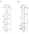
도2는 깊이별 센서 배치에 대한 예시적 구성을 설명하기 위한 도면,
도3은 일 실시예에 따른 토양 측정기의 블록도,
도4는 본 발명의 제2 실시예에 따른 토양 측정기의 사시도,
도5는 제2 실시예에 따른 토양 측정기를 탐침 유닛 단위로 분해한 분해 사시도,
도6은 제2 실시예에 따른 토양 측정기의 탐침 유닛의 사시도,
도7은 탐침 유닛의 양쪽 단부의 예시적 구성을 설명하기 위한 도면, 그리고,
도8은 탐침 유닛의 내부 구성의 예시적 구성을 설명하기 위한 도면이다. 1 is a perspective view of a soil measuring instrument according to a first embodiment of the present invention,
2 is a diagram for explaining an exemplary configuration of a sensor arrangement by depth,
3 is a block diagram of a soil meter according to an embodiment,
4 is a perspective view of a soil measuring instrument according to a second embodiment of the present invention,
FIG. 5 is an exploded perspective view of the soil measuring device according to the second embodiment,
6 is a perspective view of the probe unit of the soil measuring instrument according to the second embodiment,
7 is a view for explaining an exemplary configuration of both ends of the probe unit,
8 is a view for explaining an exemplary configuration of the internal configuration of the probe unit.
이상의 본 발명의 목적들, 다른 목적들, 특징들 및 이점들은 첨부된 도면과 관련된 이하의 바람직한 실시예들을 통해서 쉽게 이해될 것이다. 그러나 본 발명은 여기서 설명되는 실시예들에 한정되지 않고 다른 형태로 구체화될 수도 있다. 오히려, 여기서 소개되는 실시예들은 개시된 내용이 철저하고 완전해질 수 있도록 그리고 당업자에게 본 발명의 사상이 충분히 전달될 수 있도록 하기 위해 제공되는 것이다.BRIEF DESCRIPTION OF THE DRAWINGS The above and other objects, features, and advantages of the present invention will become more readily apparent from the following description of preferred embodiments with reference to the accompanying drawings. However, the present invention is not limited to the embodiments described herein but may be embodied in other forms. Rather, the embodiments disclosed herein are provided so that the disclosure can be thorough and complete, and will fully convey the scope of the invention to those skilled in the art.
본 명세서에서, 어떤 구성요소가 다른 구성요소 상에 있다고 언급되는 경우에 그것은 다른 구성요소 상에 직접 형성될 수 있거나 또는 그들 사이에 제 3의 구성요소가 개재될 수도 있다는 것을 의미한다. 또한, 도면들에 있어서, 구성요소들의 두께는 기술적 내용의 효과적인 설명을 위해 과장된 것이다.In this specification, when an element is referred to as being on another element, it may be directly formed on another element, or a third element may be interposed therebetween. Further, in the drawings, the thickness of the components is exaggerated for an effective description of the technical content.
본 명세서에서 제1, 제2 등의 용어가 구성요소들을 기술하기 위해서 사용된 경우, 이들 구성요소들이 이 같은 용어들에 의해서 한정되어서는 안된다. 이들 용어들은 단지 어느 구성요소를 다른 구성요소와 구별시키기 위해서 사용되었을 뿐이다. 여기에 설명되고 예시되는 실시예들은 그것의 상보적인 실시예들도 포함한다.Where the terms first, second, etc. are used herein to describe components, these components should not be limited by such terms. These terms have only been used to distinguish one component from another. The embodiments described and exemplified herein also include their complementary embodiments.
본 명세서에서 구성요소간의 위치 관계를 설명하기 위해 사용되는 '상부(위)', '하부(아래)', '좌', '우' 등의 표현은 절대적 기준으로서의 방향을 의미하지 않고 각 도면에서의 상대적 위치를 의미할 수 있다. 그러므로 이하에서 언급되는 위치관계를 나타내는 표현들은 각각의 도면을 참조하여 설명할 때의 해당 도면에서의 상대적 위치관계를 나타낼 수 있음을 이해할 것이다. The terms 'upper', 'lower', 'left', 'right', etc. used to describe the positional relationship between components in the present specification do not mean directions as absolute references, Can be defined as the relative position of the object. It will therefore be appreciated that the expressions representing the positional relationships referred to below may represent relative positional relationships in the respective drawings when described with reference to the respective drawings.
본 명세서에서, 단수형은 문구에서 특별히 언급하지 않는 한 복수형도 포함한다. 명세서에서 사용되는 '포함한다(comprise)' 및/또는 '포함하는(comprising)'은 언급된 구성요소는 하나 이상의 다른 구성요소의 존재 또는 추가를 배제하지 않는다.In the present specification, the singular form includes plural forms unless otherwise specified in the specification. The terms "comprise" and / or "comprising" used in the specification do not exclude the presence or addition of one or more other elements.
이하 도면을 참조하여 본 발명을 상세히 설명하도록 한다. 아래의 특정 실시예들을 기술하는데 있어서 여러 가지의 특정적인 내용들은 발명을 더 구체적으로 설명하고 이해를 돕기 위해 작성되었다. 하지만 본 발명을 이해할 수 있을 정도로 이 분야의 지식을 갖고 있는 독자는 이러한 여러 가지의 특정적인 내용들이 없어도 사용될 수 있다는 것을 인지할 수 있다. 어떤 경우에는, 발명을 기술하는 데 있어서 흔히 알려졌으면서 발명과 크게 관련 없는 부분들은 본 발명을 설명하는 데 있어 혼돈을 막기 위해 기술하지 않음을 미리 언급해 둔다. BEST MODE FOR CARRYING OUT THE INVENTION Hereinafter, the present invention will be described in detail with reference to the drawings. Various specific details are set forth in the following description of specific embodiments in order to provide a more detailed description of the invention and to aid in understanding the invention. However, it will be appreciated by those skilled in the art that the present invention may be understood by those skilled in the art without departing from such specific details. In some cases, it should be mentioned in advance that it is common knowledge in describing an invention that parts not significantly related to the invention are not described in order to avoid confusion in explaining the present invention.
도1은 본 발명의 제1 실시예에 따른 토양 측정기의 사시도이다. 1 is a perspective view of a soil measuring instrument according to a first embodiment of the present invention.
도면을 참조하면, 일 실시예에 따른 토양 측정기는 탐침부(P) 및 핸들부(H)로 구성된다. 탐침부(P)는 테이퍼형의 선단부(21) 및 내부에 빈 공간이 형성된 막대 형상의 탐침부 본체(20)를 포함한다. Referring to the drawings, a soil measuring instrument according to an embodiment includes a probe unit P and a handle unit H. The probe P includes a
탐침부(P)는 토양 측정기 사용시 수직으로 지면에 삽입되는 부분으로, 일 실시예에서 탐침부(P)의 본체(20)는 강철(steel) 또는 강성을 갖는 다른 금속 재질의 원통 형상이며, 도시한 것처럼 탐침부(P) 내부에 일정 간격으로 복수개의 센싱 모듈(10)이 배치된다. 탐침부 본체(20)의 한쪽 단부에는 테이퍼 처리된 선단부(21)가 결합되어 있어, 토양을 파낼 필요없이 탐침부(P)를 지면에 찔러서 토양 내로 삽입하기 용이하도록 되어 있다. 도시한 실시예에서 선단부(21)는 대략 원뿔형상으로 도시되었지만 선단부(21)의 형상은 여기에 제한되지 않으며, 아래로 갈수록 직경이 줄어드는 형상이면 어느 형상이든 무방하다. 또한 선단부(21)와 탐침부 본체(20)가 각기 별도로 제작되어 결합될 수도 있고 처음부터 일체로 제작되어도 무방하다. The probe P is a portion to be vertically inserted into the ground when the soil measuring instrument is used. In one embodiment, the
핸들부(H)는 탐침부(P)의 선단부(21)의 반대쪽 단부에 연결되어 배치되고 사용자가 파지(grip)할 수 있는 표면 구조를 가진다. 도시한 실시예에서, 핸들부(H)는 탐침부 본체(20)의 직경과 동일하거나 그보다 큰 직경을 갖는 통 형상의 핸들부 본체(30) 및 이 본체(30)의 측면에서 좌우로 돌출되어 뻗어있는 한 쌍의 손잡이(31)를 포함할 수 있다. 이러한 구성에 따라, 토양 측정시 사용자가 한 쌍의 손잡이(31)를 잡고 탐침부(P)를 토양에 수직으로 찔러서 토양 내로 삽입할 수 있다. The handle portion H is connected to the opposite end of the
대안적 실시예에서, 핸들부(H)는 포크레인이나 타공 장치 등의 다른 장비에 연결되어 기계적 힘에 의해 토양에 삽입될 수 있다. 예를 들어 탐침부(P)의 길이가 수 미터가 되면 사람의 힘으로 토양에 삽입하기 곤란할 수 있으므로 이러한 경우 탐침부(P)가 타공 장치에 결합되어 사용될 수 있다. 이를 위해, 대안적 실시예의 핸들부(H)가 예컨대 타공 장치에 결합되는 결합구조를 가질 수 있다. In an alternative embodiment, the handle portion H may be connected to other equipment, such as a fork-lift or perforator, and inserted into the soil by mechanical forces. For example, when the length of the probe P is several meters, it may be difficult to insert the probe into the soil by the force of a person. In this case, the probe P may be used in combination with the perforator. To this end, the handle portion H of the alternative embodiment may have a coupling structure, for example, coupled to a perforation device.
이와 같이 탐침부(P)가 인력에 의해 또는 기계적 힘에 의해 토양에 삽입되면,복수개의 센싱 모듈(10)이 서로 일정 거리 이격되어 있으므로 각 센싱 모듈(10)이 토양의 서로 다른 깊이에 위치하게 되므로, 토양 내의 서로 다른 깊이에서 토양의 물리성을 각각 측정할 수 있다. When the probes P are inserted into the soil by gravity or mechanical force, the plurality of
일 실시예에서 각 센싱 모듈(10)은 복수개의 토양 물리성을 측정하기 위해 복수개의 센서를 포함한다. 예를 들어 센싱 모듈(10)은 토양수분 센서, 전기 전도도 센서, 간극수압 센서, 온도 센서, 압력센서, 기울기 센서, 및 충격 센서 중 적어도 2개 이상의 센서를 포함할 수 있다. In one embodiment, each
센싱 모듈(10)에 포함될 센서들은 사용자가 측정하고자 하는 목적이나 상황에 따라 달라질 수 있다. 예를 들어 토양의 가뭄 정도를 측정하기 위해서는 센싱 모듈(10)이 적어도 토양수분 센서와 전기 전도도 센서를 포함하는 것이 바람직하며, 다른 예로서 지질학적 조사를 할 경우에는 예컨대 간극수압 센서, 온도센서, 기울기 센서, 충격 센서 등이 탑재된 센싱 모듈(10)이 사용될 수 있다. Sensors to be included in the
바람직한 일 실시예에서, 탐침부(P)에 설치되는 센싱 모듈(10)의 개수와 간격이 다양하게 조합되어 제조될 수 있다. 이와 관련하여 도2는 측정 대상인 토양의 종류에 따른 센싱 모듈(10)의 적절한 배치를 예로서 나타내었다. In a preferred embodiment, the number and spacing of the
도2의 (a)는 예컨대 진흙과 같이 작은 입자로 이루어진 토양의 가뭄 정도를 측정할 때 사용가능한 토양 측정기를 예시한 것으로, 도시한 것처럼 0.3m 등간격으로 배치된 복수개의 센싱 모듈(10)을 포함하는 탐침부(P)가 사용될 수 있다. 이 때 각각의 센싱 모듈(10)은 적어도 토양수분 센서와 전기전도도 센서를 포함하는 것이 바람직하다. 도면에서는 4개의 센싱 모듈(10)을 도시하였지만, 예컨대 탐침부(P)가 일정 등간격으로 배치된 3개 또는 5개 이상의 센싱 모듈(10)을 포함하는 것도 가능함은 물론이다. FIG. 2 (a) illustrates a soil measuring instrument that can be used to measure the degree of drought of soil composed of small particles such as clay. As shown in FIG. 2, a plurality of
도2의 (b)는 예컨대 마사토와 같이 굵은 입자로 이루어진 토양의 가뭄 정도를 측정할 때 사용가능한 토양 측정기를 예시한 것으로, 도시한 것처럼 위에서 차례로 1m, 0.3m, 0.2m 간격으로 3개의 센싱 모듈(10)이 배치된 탐침부(P)를 사용할 수 있다. 그러나 이러한 간격은 예시적으로 것으로, 대안적 실시예에서 예컨대 위에서 차례로 1m, 0.5m, 0.3m, 0.2m 간격으로 4개의 센싱 모듈(10)이 배치된 탐침부(P)를 사용할 수도 있을 것이다. FIG. 2 (b) illustrates a soil measuring instrument which can be used to measure the degree of drought of a soil composed of coarse particles such as Masato. As shown in the figure, three sensing modules The probe unit P having the
이와 같이 본 발명의 일 실시예에 따르면 복수개의 센싱 모듈(10) 중 서로 이웃하는 센싱 모듈 간의 거리가 모두 동일하거나, 핸들부(H)에서 점차 멀어지는 방향으로 센싱 모듈(10) 간의 거리가 점차 감소하거나 또는 점차 증가하도록 복수개의 센싱 모듈(10)을 배치할 수 있다. 그러므로 예컨대 센싱 모듈(10)의 이격 거리와 개수를 각각 다르게 구성한 다양한 토양 측정기들을 미리 마련하여 놓고, 사용자는 이들 토양 측정기들 중 측정대상인 토양의 종류나 특성에 따라 적절한 토양 측정기를 선택하여 사용할 수 있다. As described above, according to the embodiment of the present invention, the distances between adjacent sensing modules of the plurality of
도3은 일 실시예에 따른 토양 측정기의 예시적 블록도로서, 일 예로서 탐침부(P)가 3개의 센싱 모듈(10)을 포함하는 경우를 가정한 것이다. FIG. 3 is an exemplary block diagram of a soil measuring instrument according to an embodiment, assuming that the probe P includes three
도면을 참조하면, 토양 측정기의 핸들부(H)의 본체(30)가 제어부(310), 전원(320), 통신부(330), 및 사용자 인터페이스(340)를 포함할 수 있다. 제어부(310)는 복수개의 센싱 모듈(10)의 각각에 제어신호를 송신하고 각 센싱 모듈(10)로부터 데이터를 수신한다. 전원(320)은 제어부(310), 통신부(330), 사용자 인터페이스(340), 및 복수개의 센싱 모듈(10)의 각각이 동작할 수 있도록 전력을 공급한다. Referring to the drawings, a
통신부(330)는 센싱 모듈(10)로부터 수신한 데이터를 외부의 장치로 전송하는 역할을 한다. 예를 들어 본 발명에 따른 토양 측정기가 WiFi, WSN, LAN, 블루투스, 인터넷 등의 유선/무선 통신망을 통해 외부의 게이트웨이, 휴대용 컴퓨터, 데스크탑 컴퓨터, 서버 등의 외부 장치와 연결되어 있을 때, 통신부(330)는 센싱 모듈(10)이 측정한 데이터를 해당 외부 장치로 송신할 수 있다. The
사용자 인터페이스(340)는 토양 측정에 관한 사용자 명령을 수신하고 사용자에게 토양 측정 데이터 등 각종 정보를 보여주는 인터페이스로서, 예컨대 디스플레이, 터치스크린, 각종 조작 버튼이나 스위치 등을 포함할 수 있다. The
도시한 실시예에서는 통신부(330)와 사용자 인터페이스(340)를 도시하였지만, 구체적 실시 형태에 따라 예컨대 통신부(330)나 인터페이스(340)가 없어도 무방하다. 그리고 프로세서나 메모리, 저장장치 등 구성요소가 본 발명의 토양 측정기에 필요할 수 있지만, 본 발명의 설명의 편의를 위해 생략하였음을 이해할 것이다. Although the
또한 도시한 실시예에서는 핸들부(H)의 본체(30)에 제어부(310) 등의 구성요소가 설치된 것으로 도시하였지만, 이들 구성요소의 물리적 위치가 달라져도 무방하다. 예를 들어 제어부(310) 등의 구성요소가 탐침부(P)의 본체(20) 내부에 배치될 수도 있고 다른 예로서 핸들부(H)의 손잡이(31) 내에 배치될 수도 있을 것이다. In the illustrated embodiment, the
한편 도시한 실시예에서 복수개의 센싱 모듈(10)은 복수개의 전선에 의해 제어부(310) 및 전원(320)과 전기적으로 연결되어 있다. 일 실시예에서 전원(320)은 각 센싱 모듈(10)의 (+)단자 및 (-)단자와 연결된 전선을 통해 각 센싱 모듈(10)에 전원을 공급할 수 있다. 제어부(310)는 각 센싱 모듈(10)의 A단자 및 B단자와 연결된 전선을 통해 각 센싱 모듈(10)에 제어신호를 전송하고 각 센싱 모듈(10)은 이 전선을 통해 데이터를 제어부(310)로 전송할 수 있다. In the illustrated embodiment, the plurality of
제어부(310)와 각 센싱 모듈(10) 간의 통신은 공지의 다양한 통신 방식 중 하나를 사용하여 구현할 수 있다. 예를 들어 일 실시예에서 RS-485 통신 방식을 사용할 수 있다. RS-485 방식을 사용하는 경우, 우선 제어부가 각 센싱 모듈(10)마다 미리 할당된 식별 번호 중 어느 하나의 식별번호 및 식별된 센싱 모듈의 측정 데이터를 요청하는 요청 신호를 포함하는 제어신호를 복수개의 센싱 모듈(10) 전체에 전송한다. 예를 들어, 제어부(310)가 3개의 센싱 모듈 중 제1 센싱 모듈의 식별 번호 및 이 제1 센싱 모듈의 데이터를 요청하는 요청 신호를 포함한 제어신호를 A단자의 통신 라인을 통해 제1 내지 제3 센싱 모듈 전체에 전송한다. The communication between the
제1 내지 제3 센싱 모듈 중 해당 식별 번호가 할당된 센싱 모듈(즉 본 예에서는 제1 센싱 모듈)은 자신이 측정한 센싱 데이터를 자신의 식별 번호와 함께 예컨대 A단자의 통신 라인(B단자의 통신 라인이어도 무방함)을 통해 제어부(310)로 전송한다. 이 때 제2 및 제3 센싱 모듈은 제어부(310)로부터 받은 식별번호가 자신들의 식별 번호가 아니므로 특별한 동작을 하지 않아도 무방하다. The sensing module (i.e., the first sensing module in this example) to which the corresponding identification number is allocated among the first to third sensing modules transmits the sensed data measured by itself to the communication line of the A terminal Communication line may also be used). In this case, since the identification numbers received from the
제어부(310)가 제1 센싱 모듈로부터 데이터와 식별번호를 수신한 후, 제어부(310)는 수신한 식별번호가 제1 센싱 모듈의 식별번호인지 확인하고, 맞으면 수신한 데이터를 제1 센싱 모듈의 측정 데이터로서 저장 장치(미도시)에 저장할 수 있고, 그 후 통신부(330)를 통해 외부 장치로 전송하거나 또는 사용자 모니터나 디스플레이 등의 인터페이스(340)를 통해 사용자에게 보여줄 수 있다. 제어부(310)는 이상과 같은 동작을 나머지 제2 및 제3 센싱 모듈에 대해서도 반복하여 모든 센싱 모듈로부터 데이터를 순차적으로 수신하여 데이터를 저장하거나 외부로 전송할 수 있다. After receiving the data and the identification number from the first sensing module, the
상기와 같이 도3을 참조하여 RS-485 방식에서의 제어부(310) 및 센싱 모듈(10) 간 통신 방법을 설명하였으나, 대안적으로 RS-232와 같은 다른 유선 또는 무선 통신 방식으로 제어부(310)와 센싱 모듈(10) 간 통신이 구현될 수 있음은 물론이다. 3, the communication method between the
한편 제어부(310)와 전원(320)에 각각 연결된 센싱 모듈(10)은 당업계에 공지된 센싱 모듈을 사용할 수 있으며, 예를 들어 도8에 도시한 바와 같이 센싱 모듈(10)이 복수개의 센서(11) 및 이 센서와 전기적으로 결합된 회로보드(12)로 구성될 수 있다. 도8의 센싱 모듈(10)에 대해서는 후술하기로 한다. Meanwhile, the
이제 도4 내지 도8을 참조하여 제2 실시예에 따른 토양 측정기를 설명한다. Now, a soil measuring instrument according to a second embodiment will be described with reference to Figs. 4 to 8. Fig.
도4는 본 발명의 제2 실시예에 따른 토양 측정기의 사시도이고 도5는 토양 측정기를 탐침유닛 단위로 분해한 분해 사시도이다. FIG. 4 is a perspective view of a soil measuring device according to a second embodiment of the present invention, and FIG. 5 is an exploded perspective view of the soil measuring device in units of probe units.
도면을 참조하면, 제2 실시예에 따른 토양 측정기는 탐침부(P) 및 핸들부(H)를 포함하되, 탐침부(P)가 일렬로 연결된 복수개의 탐침 유닛(40)으로 구성되는 점에서 제1 실시예와 차이가 있다. Referring to the drawings, the soil measuring apparatus according to the second embodiment includes a probe unit P and a handle unit H, wherein the probe unit P includes a plurality of
일 실시예에서 탐침부(P)는 테이퍼 형상의 선단부(41) 및 막대 형상의 복수개의 탐침 유닛(40)을 포함한다. 선단부(41)는 일련의 연결된 탐침 유닛(40)의 한쪽 단부에 결합되며, 단부가 테이퍼 처리되어 사용자가 토양을 파낼 필요없이 탐침부(P)를 지면에 찔러서 토양 내로 삽입하기 용이하도록 되어 있다. 탐침 유닛(40)의 각각은 소정 길이를 갖는 강철 또는 강성을 갖는 임의의 금속 재질의 원통 형상을 가질 수 있고, 중공 내부에 센싱 모듈(10)을 하나씩 포함한다. 탐침 유닛(40)의 양쪽 단부에는 다른 탐침 유닛(40)과 결합할 수 있도록 예컨대 나사산 등의 결합구조가 형성되어 있으며, 따라서 사용자가 도5에서와 같이 각기 분리되어 있던 선단부(41), 탐침 유닛(40), 및 핸들부(H)를 일렬로 간단히 조립하여 도4에서와 같이 토양 측정기를 완성할 수 있다. In one embodiment, the probe P includes a tapered
센싱 모듈(10)은 도1 내지 도3을 참조하여 상술한 제1 실시예의 센싱 모듈과 동일 또는 유사한 구성 및 기능을 가진다. 즉 하나의 센싱 모듈은 복수개의 토양 물리성을 측정하기 위한 복수개의 센서를 포함할 수 있고, 예컨대 센싱 모듈(10)은 토양수분 센서, 전기 전도도 센서, 간극수압 센서, 온도 센서, 압력센서, 기울기 센서, 및 충격 센서 중 적어도 2개 이상의 센서를 포함할 수 있다. The
핸들부(H)는 일련의 연결된 탐침 유닛(40)의 다른쪽 단부, 즉 선단부(41)의 반대쪽 단부에 연결되며 사용자가 파지할 수 있는 표면 구조를 가진다. 도시한 실시예에서 핸들부(H)는 탐침 유닛(40)의 직경과 동일하거나 그보다 큰 직경을 갖는 통 형상의 핸들부 본체(50) 및 이 본체(50)의 측면에서 좌우로 돌출되어 뻗어있는 한 쌍의 손잡이(51)를 포함할 수 있다. 제1 실시예에서 상술하였듯이, 대안적 실시예에서 핸들부(H)는 타공 장치 등 외부 장비에 결합될 수 있는 결합구조를 가질 수 있고, 이에 따라 인력이 아니라 기계적 힘으로 탐침부(P)를 토양에 삽입할 수 있다. The handle portion H is connected to the other end of the series of
이러한 구성에 따라, 탐침부(H)가 토양에 삽입될 때 각각의 탐침 유닛(40)에 하나씩 배치된 센싱 모듈(10)이 토양의 서로 다른 깊이에 위치함으로써 토양 내의 서로 다른 깊이에서 토양 물리성을 각각 측정할 수 있다. According to this configuration, the
바람직한 일 실시예에서, 탐침부(P)에 설치되는 탐침 유닛(40)은 다양한 길이 및/또는 다양한 종류의 센서를 포함하도록 제작될 수 있다. 예를 들어 탐침 유닛(40)은 각각 1m, 0.5m, 0.3m, 그리고 0.2m 길이를 갖는 탐침 유닛으로 제작될 수 있다. 다른 예로서, 탐침 유닛(40)은 토양수분 센서, 전기 전도도 센서, 간극수압 센서, 온도 센서, 압력센서, 기울기 센서, 및 충격 센서 중 적어도 2개 이상의 센서의 조합으로 구성된 센싱 모듈(10)을 하나씩 구비할 수 있다. In a preferred embodiment, the
이러한 구성에 따라, 사용자는 토양 종류나 측정 목적 등에 따라 다양한 길이 및/또는 다양한 종류의 센서의 탐침 유닛(40)들을 조합하여 자신의 용도에 맞는 토양 측정기를 임의로 구성할 수 있다. 예컨대 도2를 다시 참조하면, 사용자는 선단부(41), 0.3m 길이의 탐침 유닛(40) 4개, 그리고 핸들부(H)를 일렬로 결합함으로써 도2의 (a)와 같은 토양 측정기를 만들 수 있다. 또 다른 예로서, 사용자가 선단부(41), 0.2m 길이 탐침 유닛(40), 0.3m 길이 탐침 유닛(40), 1m 길이 탐침 유닛(40), 그리고 핸들부(H)를 일렬로 결합하여 도2의 (b)와 같은 토양 측정기를 만들 수도 있다. According to such a configuration, the user can arbitrarily configure a soil measuring instrument suitable for his or her use by combining
도6 내지 도8은 이러한 제2 실시예에 따른 탐침 유닛(40)의 예시적 구성을 나타낸다. 도6은 탐침 유닛(40)의 사시도이고, 도7의 (a)와 (b)는 도6의 탐침 유닛(40)을 A 방향과 B 방향에서 바라본 단부를 각각 나타낸다. 그리고 도8은 탐침 유닛(40)의 분해 사시도이다. 6 to 8 show an exemplary configuration of the
도6 내지 도8을 참조하면, 일 실시예에 따른 탐침 유닛(40)은 분리가능한 캡(410) 및 케이스(420)로 구성될 수 있다. 케이스(420)는 원통 형상의 본체(421) 및 한쪽 단부에 형성된 연결부(422)를 포함한다. 케이스(420)의 한쪽 단부는 연결부(422)에 의해 폐쇄되어 있고 다른쪽 단부는 개방되어 있다. 개방된 단부의 내측에는 나사산(424)이 형성되어 있어 캡(410)과 결합될 수 있다. 6 through 8, the
캡(410)은 케이스(420)와 대략 동일한 외경의 원통 형상을 갖는 캡 본체(411), 및 캡 본체(411)의 한쪽 단부의 외주면에 회전가능하게 결합된 회전 너트(412) 및 다른쪽 단부에 형성되고 케이스(420)의 나사산(424)과 맞물리도록 구성된 나사산 연결부(414)를 포함한다. 캡(410)의 상기 회전 너트(412)가 있는 쪽의 단부는 연결단자 구조에 의해 폐쇄되어 있고 나사산 연결부(414) 쪽의 단부는 개방되어 있다. 이러한 캡(410) 및 케이스(420)의 구성에 따라, 캡(410)의 나사산 연결부(414)와 케이스(420)의 내측 나사산(424)이 맞물리면서 캡(410)과 케이스(420)가 결합되어 도6에 도시한 것과 같이 밀폐된 내부 공간을 갖는 탐침 유닛(40)이 된다. 캡(410)과 케이스(420)가 결합된 탐침 유닛(40)의 전체 길이는 위에서 설명한 것처럼 1m, 0.5m, 0.3m, 0.2m 등 다양한 길이 중 하나일 수 있다. The
탐침 유닛(40) 양쪽 단부의 연결 구조에 대해, 도7의 (a)는 도6의 A측의 단부를 나타내며, 도시한 것처럼 캡(410)의 회전 너트(412)에 의해 둘러싸인 2종류의 단자(415,417)가 형성되어 있다. 회전 너트(412)의 내측에는 나사산(413)이 형성되어 있으며, 이 나사산(413)은 케이스(420)의 연결부(422)의 나사산과 맞물리는 구조를 가진다. 6 (a) shows the end on the side of Fig. 6, and as shown in Fig. 6, two types of terminals (not shown) surrounded by a
일 실시예에서, 2종류의 단자(415,417) 중 핀 형상의 단자(415)는 전원 단자이며, 예컨대 도3에서 전원(320)과 센싱 모듈(10)을 연결하는 라인에 대응한다. 단자(415,417) 중 소켓 형상의 단자(417)는 통신 단자이며, 예컨대 도3에서 제어부(310)와 센싱 모듈(10)을 연결하는 라인에 대응한다. In one embodiment, the pin-shaped
도7의 (b)는 도6의 B측 단부를 나타내며, 이 단부는 도7의 (a)의 단부와 맞물리는 구조를 가진다. 도7의 (b)에 도시한 것처럼 케이스(420)의 연결부(422)쪽 단부는 연결부(422)에 의해 둘러싸인 2종류의 단자(425,427)를 포함하며, 도7의 (a)의 단자구조와 반대로 핀 형상의 단자(427)가 통신 단자이고 소켓 형상의 단자(425)가 전원 단자이다. 따라서, 예컨대 두 개의 탐침 유닛('제1 탐침 유닛' 및 '제2 탐침 유닛')이 일렬로 결합될 때, 제1 탐침 유닛의 캡(410) 쪽의 핀형 전원 단자(415)와 제2 탐침 유닛의 케이스(420) 쪽의 소켓형 전원 단자(425)가 연결되고 제1 탐침 유닛의 캡(410) 쪽의 소켓형 통신 단자(417)와 제2 탐침 유닛의 케이스(420) 쪽의 핀형 통신 단자(427)가 각각 연결된다. 그리고 이 때 제1 탐침 유닛의 회전 너트(412)를 회전시킴에 따라 회전 너트(412) 내측의 나사산(413)과 제2 탐침 유닛의 연결부(422)의 나사산이 맞물리게 되어 제1 탐침 유닛과 제2 탐침 유닛이 물리적 전기적으로 결합된다. Fig. 7 (b) shows the B-side end portion of Fig. 6, and this end portion has a structure of engaging with the end portion of Fig. 7 (a). 7 (b), the end of the
한편 도8에 도시한 것처럼 탐침 유닛(40) 내에 배치되는 센싱 모듈(10)도 교체 가능하게 구성될 수 있다. 도8을 참조하면 탐침 유닛(40)의 캡(410)은 외부의 단자(415,417)와 전기적으로 연결된 내부 커넥터(419)를 포함하고, 케이스(420)는 외부의 단자(425,427)와 전기적으로 연결된 내부 커넥터(429)를 포함한다. On the other hand, as shown in FIG. 8, the
커넥터(419)는 4핀이 삽입되는 소켓형 커넥터이고, 커넥터(429)는 4핀형 커넥터이다. 이 실시예에서 핀이 4개인 이유는, 도3 및 도7에서와 같이 전원용의 2개 단자 및 통신용의 2개 단자가 사용되기 때문으로, 대안적 실시예에서 통신 방식이 상이하면 핀과 소켓의 구성이 달라질 수 있음은 물론이다. The
도시한 실시예에서, 센싱 모듈(10)은 센서(11)와 회로보드(12)로 구성되고 양쪽 단부로 돌출된 커넥터(13,14)를 포함할 수 있다. 센서(11)는 수분센서, 전기 전도도 센서, 간극수압 센서, 온도 센서, 압력센서, 기울기 센서, 및 충격 센서 중 적어도 2개 이상의 센서를 포함할 수 있다. 도시한 실시예에서는 센서(11)를 대략 원기둥 형상으로 도시하였지만, 센서의 종류 등에 따라 센서(11) 형상이 달라질 수 있음은 물론이다. In the illustrated embodiment, the
회로보드(12)에는 제어부(310) 및 전원(320)과 센서(11) 사이에 개재되어 필요한 기능을 수행하는 회로소자들이 실장된다. 예를 들어, 센서(11)로부터의 센싱 데이터를 수신하고 임시 저장하는 메모리 및/또는 저장부, 제어부(310)로부터 수신한 제어신호를 해석하고 센싱 데이터를 제어부(310)로 전송하는 제어회로, 전원(320)으로부터 공급받은 전압 또는 전류 중 일부를 센서(11)에 공급하는 전원 관련 회로 등을 포함할 수 있다. The
회로보드(12)의 한쪽 단부에 결합된 커넥터(13)는 예컨대 4핀이 삽입되는 소켓형 커넥터이고, 케이스(420)의 내부 커넥터(429)와 연결될 수 있다. 센서(11) 쪽의 커넥터(14)는 회로보드(12)에서 도출된 4가닥 전선(즉, 전원용의 2개 전선 및 통신용의 2개 전선)이 센서(11)의 측면을 통과하여 센서(11)의 앞쪽으로 뻗어나와 형성된 것으로 4핀형 커넥터이고, 캡(410)의 내부 커넥터(419)와 연결될 수 있다. The
이러한 구성에 따라, 센싱 모듈(10)의 커넥터(13,14)와 탐침 유닛(40)의 내부 커넥터(429,419)를 각각 서로 연결/분리함으로써 센싱 모듈(10)을 쉽게 교체할 수 있으며, 측정하고자 하는 토양의 종류나 측정 목적에 따라 센서를 다양하게 교체하면서 탐침 유닛(40)의 케이스를 계속 재사용할 수 있다. 따라서 상술한 본 발명의 제2 실시예에 따르면, 여러 길이의 탐침 유닛(40)의 외부 케이스와 여러 종류의 센싱 모듈(10)을 서로 다양하게 조합하여 토양 측정기를 구성할 수 있으므로 측정 대상인 토양의 종류, 측정 목적이나 항목 등의 조건에 맞게 사용자가 토양 측정기를 맞춤 구성할 수 있다. According to this configuration, the
한편 도6 내지 도8에서는 특정 형상의 연결구조 및 단자 구조를 도시하였고 이에 기초하여 본 발명의 실시예를 설명하였지만, 탐침 유닛(40)을 서로 물리적, 전기적으로 결합하기 위해 당업계에 공지된 다양한 결합방식과 통신방식, 그리고 단자 형식을 조합하여 사용할 수 있다. 그러므로 도면에 도시한 구성은 단지 본 발명의 예시적 실시예에 지나지 않으며, 본 발명의 탐침 유닛(40)이 어느 특정 결합방식이나 단자 구조에 한정되지 않음을 당업자는 이해할 것이다. 6 to 8 illustrate connection structures and terminal structures of specific shapes and illustrate embodiments of the present invention based thereon. However, in order to physically and electrically couple the
이와 같이 본 발명이 속하는 분야에서 통상의 지식을 가진 자라면 이러한 명세서의 기재로부터 다양한 수정 및 변형이 가능함을 이해할 수 있으며, 그러므로 본 발명의 범위는 설명된 실시예에 국한되어 정해져서는 아니되며 후술하는 특허청구범위뿐 아니라 이 특허청구범위와 균등한 것들에 의해 정해져야 한다.It will be apparent to those skilled in the art that various modifications and variations can be made in the present invention without departing from the spirit and scope of the invention as defined by the appended claims and their equivalents. And should be determined by equivalents to the scope of the appended claims.
10: 센싱 모듈
11: 센서
12: 회로보드
13, 14: 커넥터
20: 탐침부 본체
30, 50: 핸들부 본체
40: 탐침 유닛
310: 제어부
320: 전원
330: 통신부
340: 사용자 인터페이스
410: 캡
420: 케이스10: Sensing module
11: Sensor
12: Circuit board
13, 14: Connector
20: probe main body
30, 50: handle body
40: probe unit
310:
320: Power supply
330:
340: User interface
410: cap
420: Case
Claims (12)
테이퍼형 일 단부를 가지며 내부에 빈공간이 형성된 막대 형상의 탐침부; 및
상기 탐침부의 타 단부에 배치되고, 사용자가 파지하거나 또는 타 장치에 결합될 수 있는 핸들부;를 포함하고,
상기 탐침부는 탐침부 내부에 소정 간격으로 이격되어 배치된 복수개의 센싱 모듈을 포함하고,
상기 탐침부가 토양에 삽입될 때 상기 복수개의 센싱 모듈이 토양의 서로 다른 깊이에 위치함으로써 토양 내의 서로 다른 깊이에서 토양 물리성을 각각 측정할 수 있는 것을 특징으로 하는 토양 측정기. In a soil meter,
A rod-shaped probe having a tapered one end and an empty space formed therein; And
And a handle portion disposed at the other end of the probe portion and capable of being held by a user or coupled to another device,
Wherein the probe unit includes a plurality of sensing modules disposed at predetermined intervals in the probe unit,
Wherein the plurality of sensing modules are located at different depths of the soil when the probe part is inserted into the soil, so that soil physical properties can be measured at different depths in the soil, respectively.
상기 복수개의 센싱 모듈 중 서로 이웃하는 센싱 모듈 간의 거리가 모두 동일하거나 또는 상기 핸들부에서 점차 멀이지는 방향으로 상기 센싱 모듈 간의 거리가 점차 감소하도록 상기 복수개의 센싱 모듈이 배치된 것을 특징으로 하는 토양 측정기. The method according to claim 1,
Wherein the plurality of sensing modules are disposed such that distances between adjacent sensing modules of the plurality of sensing modules are all the same or a distance between the sensing modules gradually decreases in a direction that is gradually distant from the handle portion. Measuring instrument.
상기 복수개의 센싱 모듈의 각 센싱 모듈이, 수분센서, 전기 전도도 센서, 간극수압 센서, 온도 센서, 압력센서, 기울기 센서, 및 충격 센서 중 적어도 2개 이상의 센서를 포함하는 것을 특징으로 하는 토양 측정기. 3. The method of claim 2,
Wherein each sensing module of the plurality of sensing modules includes at least two sensors among a moisture sensor, an electric conductivity sensor, a pore pressure sensor, a temperature sensor, a pressure sensor, a tilt sensor, and an impact sensor.
상기 복수개의 센싱 모듈의 각각에 제어신호를 송신하고 각 센싱 모듈로부터 데이터 신호를 수신하는 제어부; 및
상기 제어부와 상기 복수개의 센싱 모듈의 각각에 전력을 공급하는 전원;을 포함하는 것을 특징으로 하는 토양 측정기. The method of claim 3,
A control unit for transmitting a control signal to each of the plurality of sensing modules and receiving a data signal from each sensing module; And
And a power supply for supplying power to the control unit and the plurality of sensing modules, respectively.
상기 제어부가 (i) 상기 복수개의 센싱 모듈 중 제1 센싱 모듈을 식별하는 제1 식별신호; 및 (ii) 식별된 센싱 모듈로부터 센싱 데이터를 요청하는 요청 신호;를 포함하는 제어신호를 상기 복수개의 센싱 모듈에 전송하면, 상기 제1 센싱 모듈이 센싱 데이터를 상기 제어부로 전송하는 것을 특징으로 하는 토양 측정기. 5. The method of claim 4,
Wherein the control unit comprises: (i) a first identification signal identifying a first one of the plurality of sensing modules; And (ii) a request signal for requesting sensing data from the identified sensing module to the plurality of sensing modules, the first sensing module transmits the sensing data to the control unit Soil Meter.
테이퍼 형상의 선단부 및 막대 형상의 복수개의 탐침 유닛이 일렬로 결합된 탐침부; 및
상기 탐침부의 상기 선단부의 반대쪽 단부에 배치되고, 사용자가 파지하거나 또는 타 장치에 결합될 수 있는 핸들부;를 포함하고,상기 복수개의 탐침 유닛의 각각은 복수개 종류의 센서를 포함하는 센싱 모듈을 하나씩 포함하고,
상기 탐침부가 토양에 삽입될 때 각각의 센싱 모듈이 토양의 서로 다른 깊이에 위치함으로써 토양 내의 서로 다른 깊이에서 토양 물리성을 각각 측정할 수 있는 것을 특징으로 하는 토양 측정기. In a soil meter,
A probe unit having a tapered tip portion and a plurality of rod-shaped probe units coupled together in a row; And
And a handle portion disposed at an opposite end of the tip portion of the probe portion, the handle portion being capable of being held by a user or coupled to another device, wherein each of the plurality of probe units includes a sensing module including a plurality of types of sensors Including,
Wherein each sensing module is positioned at different depths of the soil when the probe is inserted into the soil, whereby soil physical properties can be measured at different depths in the soil, respectively.
상기 복수개의 탐침 유닛의 길이가 모두 동일하거나 또는 상기 핸들부에서 점차 멀어지는 방향으로 각 탐침 유닛의 길이가 점차 감소하도록 상기 복수개의 탐침 유닛이 결합된 것을 특징으로 하는 토양 측정기. The method according to claim 6,
Wherein the plurality of probe units are coupled such that the length of each probe unit gradually decreases in the direction in which the plurality of probe units are all the same length or are gradually moved away from the handle portion.
상기 복수개의 탐침 유닛의 각 센싱 모듈에 제어신호를 송신하고 각 센싱 모듈로부터 데이터 신호를 수신하는 제어부; 및
상기 제어부와 상기 각 센싱 모듈에 전력을 공급하는 전원;을 포함하는 것을 특징으로 하는 토양 측정기. The method according to claim 6,
A control unit for transmitting a control signal to each sensing module of the plurality of probe units and receiving a data signal from each sensing module; And
And a power supply for supplying power to the control unit and each of the sensing modules.
상기 각각의 센싱 모듈이, 수분센서, 전기 전도도 센서, 간극수압 센서, 온도 센서, 압력센서, 기울기 센서, 및 충격 센서 중 적어도 2개 이상의 센서를 포함하는 것을 특징으로 하는 토양 측정기. 9. The method of claim 8,
Wherein each of the sensing modules includes at least two sensors among a moisture sensor, an electric conductivity sensor, a pore pressure sensor, a temperature sensor, a pressure sensor, a tilt sensor, and an impact sensor.
각각의 상기 탐침 유닛은 제1 단부에 형성된 제1 연결단자 및 상기 제1 단부에 대향하는 제2 단부에 형성되고 상기 제1 연결단자와 전기적으로 맞물리는 제2 연결단자를 포함하고,
상기 탐침 유닛 내에 배치된 상기 센싱 모듈이 상기 제1 연결단자와 상기 제2 연결단자에 각각 전기적으로 연결된 것을 특징으로 하는 토양 측정기.10. The method of claim 9,
Each of said probe units includes a first connection terminal formed at a first end and a second connection terminal formed at a second end opposite to said first end and electrically engaged with said first connection terminal,
And the sensing module disposed in the probe unit is electrically connected to the first connection terminal and the second connection terminal, respectively.
상기 제1 연결단자와 제2 연결단자의 각각은 전원단자 및 신호단자를 포함하고,
상기 전원단자를 통해 상기 전원으로부터 상기 각각의 센싱 모듈로 전력이 공급되고,
상기 신호단자를 통해 상기 제어부와 상기 각 센싱 모듈 간의 제어신호 및 데이터 신호의 송수신이 이루어지는 것을 특징으로 하는 토양 측정기.11. The method of claim 10,
Wherein each of the first connection terminal and the second connection terminal includes a power supply terminal and a signal terminal,
Power is supplied from the power source to each of the sensing modules via the power terminal,
And a control signal and a data signal are transmitted and received between the control unit and each sensing module through the signal terminal.
각각의 상기 탐침 유닛이 케이스(420)와 캡(410)으로 분리 가능하되,
상기 케이스(420)는 상기 제1 연결단자가 형성된 상기 제1 단부 및 이에 대향하는 개방된 제3 단부를 갖는 원통 형상이고,
상기 캡(410)은 상기 제2 연결단자가 형성된 상기 제2 단부 및 이에 대향하는 개방된 제4 단부를 갖는 원통 형상이고,
상기 제3 단부와 상기 제4 단부가 탈착 가능하게 결합될 수 있고,
상기 제3 단부와 상기 제4 단부가 결합되면 상기 탐침 유닛이 밀폐되고, 상기 제3 단부와 상기 제4 단부가 서로 분리된 상태에서 상기 센싱 모듈이 상기 제1 연결단자와 상기 제2 연결단자로부터 분리되어 교체가능한 것을 특징으로 하는 토양 측정기. 11. The method of claim 10,
Each of said probe units being separable into a case 420 and a cap 410,
The case 420 is in the shape of a cylinder having the first end formed with the first connection terminal and the open third end opposed thereto,
The cap 410 is in the shape of a cylinder having the second end formed with the second connection terminal and the open fourth end opposite thereto,
The third end and the fourth end may be releasably engaged,
When the third end portion and the fourth end portion are coupled to each other, the probe unit is hermetically sealed, and the sensing module is connected to the first connection terminal and the second connection terminal The soil measuring device is characterized in that it can be separated and replaced.
Priority Applications (1)
| Application Number | Priority Date | Filing Date | Title |
|---|---|---|---|
| KR1020160163694A KR20170077783A (en) | 2016-12-02 | 2016-12-02 | Soil measuring device having a plurality of sensing modules with depth |
Applications Claiming Priority (1)
| Application Number | Priority Date | Filing Date | Title |
|---|---|---|---|
| KR1020160163694A KR20170077783A (en) | 2016-12-02 | 2016-12-02 | Soil measuring device having a plurality of sensing modules with depth |
Related Parent Applications (1)
| Application Number | Title | Priority Date | Filing Date |
|---|---|---|---|
| KR1020150187318A Division KR20170077437A (en) | 2015-12-28 | 2015-12-28 | Soil measuring device having a plurality of sensing modules with depth |
Publications (1)
| Publication Number | Publication Date |
|---|---|
| KR20170077783A true KR20170077783A (en) | 2017-07-06 |
Family
ID=59354348
Family Applications (1)
| Application Number | Title | Priority Date | Filing Date |
|---|---|---|---|
| KR1020160163694A Ceased KR20170077783A (en) | 2016-12-02 | 2016-12-02 | Soil measuring device having a plurality of sensing modules with depth |
Country Status (1)
| Country | Link |
|---|---|
| KR (1) | KR20170077783A (en) |
Cited By (4)
| Publication number | Priority date | Publication date | Assignee | Title |
|---|---|---|---|---|
| KR102308371B1 (en) * | 2020-08-07 | 2021-10-06 | (주)유비엔 | Depth control soil moisture monitoring device using broadband wireless communication and location information |
| CN115183903A (en) * | 2022-07-25 | 2022-10-14 | 中国科学院西北生态环境资源研究院 | Miniature single channel temperature acquisition device |
| KR102468014B1 (en) * | 2022-02-11 | 2022-11-17 | 신화건설㈜ | A temperature measuring module and a multi-temperature measuring instrument using thereof |
| CN117491597A (en) * | 2023-11-02 | 2024-02-02 | 惠州市精田机械制造有限公司 | Environment detection device for soil pollution treatment |
-
2016
- 2016-12-02 KR KR1020160163694A patent/KR20170077783A/en not_active Ceased
Cited By (5)
| Publication number | Priority date | Publication date | Assignee | Title |
|---|---|---|---|---|
| KR102308371B1 (en) * | 2020-08-07 | 2021-10-06 | (주)유비엔 | Depth control soil moisture monitoring device using broadband wireless communication and location information |
| KR102468014B1 (en) * | 2022-02-11 | 2022-11-17 | 신화건설㈜ | A temperature measuring module and a multi-temperature measuring instrument using thereof |
| CN115183903A (en) * | 2022-07-25 | 2022-10-14 | 中国科学院西北生态环境资源研究院 | Miniature single channel temperature acquisition device |
| CN117491597A (en) * | 2023-11-02 | 2024-02-02 | 惠州市精田机械制造有限公司 | Environment detection device for soil pollution treatment |
| CN117491597B (en) * | 2023-11-02 | 2024-04-02 | 惠州市精田机械制造有限公司 | Environment detection device for soil pollution treatment |
Similar Documents
| Publication | Publication Date | Title |
|---|---|---|
| KR20170077437A (en) | Soil measuring device having a plurality of sensing modules with depth | |
| CN103155290B (en) | Rosette | |
| EP2182593B1 (en) | System and method for sensing information that is being communicated through a connector | |
| TWM378377U (en) | Twisting force testing device | |
| KR20140092782A (en) | Apparatus for observation underground water | |
| KR101259236B1 (en) | Non-invasive medical data acquisition assembly | |
| CN104685362B (en) | analysis tool component | |
| JP2014055943A (en) | Wireless handle for battery tester, and battery tester assembly using the same | |
| CN218411267U (en) | Temperature and humidity measuring device and system | |
| US10295324B2 (en) | Measuring instrument | |
| CN211016126U (en) | Conductivity detection teaching aid for teaching | |
| CN106643912A (en) | Plant monitor and plant monitoring system with same | |
| JP6134532B2 (en) | Terminal unit and environmental test equipment with terminal unit | |
| CN209727274U (en) | Temperature sensor and temperature sensor group | |
| CN109506803A (en) | soil monitor | |
| CN214585407U (en) | Soil environment multi-element remote real-time monitoring equipment | |
| CN104502718B (en) | A kind of geology mud measuring appliance | |
| CN212872470U (en) | Novel portable soil moisture content is surveyd device | |
| CN217244370U (en) | Body fat scale | |
| ES2445625T3 (en) | Welding device with computer-based sensor system | |
| CN216746489U (en) | Carbon base temperature sensor | |
| CN209372980U (en) | Power system power consumption measuring device | |
| CN204302391U (en) | A kind of geology mud measuring appliance | |
| CN106618511A (en) | Wearable intelligent device capable of measuring body temperature | |
| CN209657482U (en) | A kind of monitoring device and system |
Legal Events
| Date | Code | Title | Description |
|---|---|---|---|
| A107 | Divisional application of patent | ||
| A201 | Request for examination | ||
| PA0107 | Divisional application |
Comment text: Divisional Application of Patent Patent event date: 20161202 Patent event code: PA01071R01D Filing date: 20151228 Application number text: 1020150187318 |
|
| PA0201 | Request for examination | ||
| A302 | Request for accelerated examination | ||
| PA0302 | Request for accelerated examination |
Patent event date: 20161209 Patent event code: PA03022R01D Comment text: Request for Accelerated Examination Patent event date: 20161202 Patent event code: PA03021R04I Comment text: Divisional Application of Patent |
|
| E902 | Notification of reason for refusal | ||
| PE0902 | Notice of grounds for rejection |
Comment text: Notification of reason for refusal Patent event date: 20161227 Patent event code: PE09021S01D |
|
| E902 | Notification of reason for refusal | ||
| PE0902 | Notice of grounds for rejection |
Comment text: Notification of reason for refusal Patent event date: 20170427 Patent event code: PE09021S01D |
|
| PG1501 | Laying open of application | ||
| E601 | Decision to refuse application | ||
| PE0601 | Decision on rejection of patent |
Patent event date: 20170921 Comment text: Decision to Refuse Application Patent event code: PE06012S01D Patent event date: 20170427 Comment text: Notification of reason for refusal Patent event code: PE06011S01I Patent event date: 20161227 Comment text: Notification of reason for refusal Patent event code: PE06011S01I |