KR20170077850A - Apparatus of omnidirectional monitoring camera - Google Patents
Apparatus of omnidirectional monitoring camera Download PDFInfo
- Publication number
- KR20170077850A KR20170077850A KR1020170077553A KR20170077553A KR20170077850A KR 20170077850 A KR20170077850 A KR 20170077850A KR 1020170077553 A KR1020170077553 A KR 1020170077553A KR 20170077553 A KR20170077553 A KR 20170077553A KR 20170077850 A KR20170077850 A KR 20170077850A
- Authority
- KR
- South Korea
- Prior art keywords
- camera
- image
- thermal
- omnidirectional
- unit
- Prior art date
- Legal status (The legal status is an assumption and is not a legal conclusion. Google has not performed a legal analysis and makes no representation as to the accuracy of the status listed.)
- Ceased
Links
Images


Classifications
-
- G—PHYSICS
- G08—SIGNALLING
- G08B—SIGNALLING SYSTEMS, e.g. PERSONAL CALLING SYSTEMS; ORDER TELEGRAPHS; ALARM SYSTEMS
- G08B13/00—Burglar, theft or intruder alarms
- G08B13/18—Actuation by interference with heat, light, or radiation of shorter wavelength; Actuation by intruding sources of heat, light, or radiation of shorter wavelength
- G08B13/189—Actuation by interference with heat, light, or radiation of shorter wavelength; Actuation by intruding sources of heat, light, or radiation of shorter wavelength using passive radiation detection systems
- G08B13/194—Actuation by interference with heat, light, or radiation of shorter wavelength; Actuation by intruding sources of heat, light, or radiation of shorter wavelength using passive radiation detection systems using image scanning and comparing systems
- G08B13/196—Actuation by interference with heat, light, or radiation of shorter wavelength; Actuation by intruding sources of heat, light, or radiation of shorter wavelength using passive radiation detection systems using image scanning and comparing systems using television cameras
- G08B13/19678—User interface
- G08B13/19689—Remote control of cameras, e.g. remote orientation or image zooming control for a PTZ camera
-
- H—ELECTRICITY
- H04—ELECTRIC COMMUNICATION TECHNIQUE
- H04N—PICTORIAL COMMUNICATION, e.g. TELEVISION
- H04N7/00—Television systems
- H04N7/18—Closed-circuit television [CCTV] systems, i.e. systems in which the video signal is not broadcast
-
- G—PHYSICS
- G08—SIGNALLING
- G08B—SIGNALLING SYSTEMS, e.g. PERSONAL CALLING SYSTEMS; ORDER TELEGRAPHS; ALARM SYSTEMS
- G08B13/00—Burglar, theft or intruder alarms
- G08B13/18—Actuation by interference with heat, light, or radiation of shorter wavelength; Actuation by intruding sources of heat, light, or radiation of shorter wavelength
- G08B13/189—Actuation by interference with heat, light, or radiation of shorter wavelength; Actuation by intruding sources of heat, light, or radiation of shorter wavelength using passive radiation detection systems
- G08B13/194—Actuation by interference with heat, light, or radiation of shorter wavelength; Actuation by intruding sources of heat, light, or radiation of shorter wavelength using passive radiation detection systems using image scanning and comparing systems
- G08B13/196—Actuation by interference with heat, light, or radiation of shorter wavelength; Actuation by intruding sources of heat, light, or radiation of shorter wavelength using passive radiation detection systems using image scanning and comparing systems using television cameras
- G08B13/19617—Surveillance camera constructional details
- G08B13/1963—Arrangements allowing camera rotation to change view, e.g. pivoting camera, pan-tilt and zoom [PTZ]
-
- H—ELECTRICITY
- H04—ELECTRIC COMMUNICATION TECHNIQUE
- H04N—PICTORIAL COMMUNICATION, e.g. TELEVISION
- H04N23/00—Cameras or camera modules comprising electronic image sensors; Control thereof
- H04N23/50—Constructional details
- H04N23/55—Optical parts specially adapted for electronic image sensors; Mounting thereof
-
- H04N5/2252—
-
- H04N5/2253—
-
- H04N5/2254—
-
- H04N5/2258—
-
- H—ELECTRICITY
- H04—ELECTRIC COMMUNICATION TECHNIQUE
- H04N—PICTORIAL COMMUNICATION, e.g. TELEVISION
- H04N5/00—Details of television systems
- H04N5/30—Transforming light or analogous information into electric information
- H04N5/33—Transforming infrared radiation
-
- H—ELECTRICITY
- H04—ELECTRIC COMMUNICATION TECHNIQUE
- H04N—PICTORIAL COMMUNICATION, e.g. TELEVISION
- H04N7/00—Television systems
- H04N7/18—Closed-circuit television [CCTV] systems, i.e. systems in which the video signal is not broadcast
- H04N7/183—Closed-circuit television [CCTV] systems, i.e. systems in which the video signal is not broadcast for receiving images from a single remote source
Landscapes
- Engineering & Computer Science (AREA)
- Multimedia (AREA)
- Signal Processing (AREA)
- Physics & Mathematics (AREA)
- General Physics & Mathematics (AREA)
- Human Computer Interaction (AREA)
- Accessories Of Cameras (AREA)
- Studio Devices (AREA)
- Closed-Circuit Television Systems (AREA)
Abstract
본 발명은 전방위 감시 카메라 장치에 관한 것이다. 본 발명의 일 실시예에 따른 전방위 감시 카메라 장치는 촬영대상지역의 열화상을 촬영하고, 수직 방향과 수평 방향으로 미리 설정된 소정의 각도로 회전되도록 설치된 열감지카메라부, 상기 열감지카메라부의 일측에 배치되어 있으며, 중앙을 기준으로 서로 대칭이 되는 다른 방향에 한쌍으로 상호 촬영되는 화각을 방위각과 고도각이 서로 다른 방향에서 각각 촬영될 수 있도록 구비하여 전방향에 대한 촬영이 가능한 전방향카메라부, 및 상기 열감지카메라부의 회전 작동과 열감지 작동을 제어하고, 상기 열감지카메라부와 상기 전방향카메라부에서 취득한 영상을 수신하여 열감지 영상 및 전방향영상을 출력하는 제어부를 포함한다.The present invention relates to an omnidirectional surveillance camera apparatus. The omnidirectional monitoring camera apparatus according to an embodiment of the present invention includes a thermal sensing camera unit configured to photograph a thermal image of a region to be imaged and to rotate at a predetermined angle set in a vertical direction and a horizontal direction, Directional camera unit capable of photographing in all directions by being provided with a view angle mutually photographed in a pair of different directions symmetrical to each other with respect to the center so that the view angle and altitude angle can be respectively photographed in different directions, And a control unit for controlling the rotation operation and the thermal sensing operation of the thermal sensing camera unit and receiving the image captured by the thermal sensing camera unit and the omnidirectional camera unit to output a thermal sensed image and an omnidirectional image.
Description
본 발명은 전방위 감시 카메라 장치에 관한 것으로, 보다 상세하게는 촬영대상지역을 감시하는 카메라 장치의 구조를 개선하여 회전에 의해 전방위로 열을 감지하면서 넓은 화각을 가져 주변을 관찰할 수 있음에 따라 열발생을 탐지하면서 열이 발생되는 원인이나 발생되는 경로, 및 주변 상황을 지속적으로 감시하여 감시 효율이 향상시킬 수 있는 전방위 감시 카메라 장치에 관한 것이다.The present invention relates to an omnidirectional surveillance camera device, and more particularly, to a camera device for monitoring an imaging target area, which can improve the structure of the omnidirectional surveillance camera device, The present invention relates to an omnidirectional surveillance camera device capable of continuously monitoring surveillance efficiency by detecting the cause of occurrence of heat, a path that occurs, and surrounding conditions.
일반적으로, 감시 카메라 장치는 사용자가 지정된 영역 내부의 영상을 촬영하고, 촬영된 영상을 관찰하여 영역 내에 화재의 발생, 허가되지 않은 사람이나 동물의 침입 등을 감시하는 장치이다.Generally, the surveillance camera device is a device for capturing an image of a user in a designated area, observing a photographed image, and monitoring the occurrence of a fire in an area, an intrusion of an unauthorized person or an animal.
이런, 감시 카메라 장치는 촬영 카메라의 시야각에 따라 촬영되는 영역이 설정되고, 설정된 촬영 영역을 촬영한 영상을 감시자가 모니터를 통해서 관찰하여 영역 내에 화재 발생, 허가되지 않은 사람이나 동물의 침입 등을 감시하도록 작동된다.In the surveillance camera device, an area to be photographed is set according to the viewing angle of the photographing camera, and a surveillant observes the photographed image of the set photographing area through a monitor to monitor a fire in the area and intrusion of unauthorized persons or animals .
이런, 통상적인 감시 카메라 장치는 촬영 카메라의 시야각을 벗어나는 사각 지대에서 촬영되지 않음에 따라 사각지대는 감시 영역에서 벗어나 감시되는 효율이 저하된다.Such a conventional surveillance camera device is not photographed in a blind spot beyond the viewing angle of the photographing camera, so that the blind spot is detached from the surveillance area and the efficiency of being monitored deteriorates.
상술되는 사각 지대는 촬영 카메라가 촬영을 할 수 없는 영역으로 감시 영역에서 벗어남에 따라 허가되지 않은 사람이나 동물이 침입하거나 화재가 발생되어도 감시될 수 없어 감시 효율이 저하된다.The blind spot described above can not be monitored even if an unauthorized person or animal enters or fires as the camera moves off the surveillance area to an area where shooting is not possible, resulting in lowered monitoring efficiency.
이에 최근에는 촬영 카메라에 360도 회전되는 구동 장치가 설치되어 회전되면서 촬영을 실시함에 따라 회전에 의해 촬영되는 영역을 확대하여 사각지대가 최소화되어 감시효율이 향상되는 감시 카메라 장치가 개발되어 사용되고 있다.In recent years, a surveillance camera device has been developed and used, in which a driving device that rotates 360 degrees is installed on a photographing camera, and photographing is performed by rotating the photographing camera to enlarge an area photographed by rotation so that a blind spot is minimized to improve monitoring efficiency.
이런, 종래 기술의 감시 카메라 장치는 일방향을 향해서 촬영을 실시하는 촬영 카메라를 구동 장치의 작동으로 회전시키면서 회전되는 궤적을 따라서 촬영되는 영역이 확대되고, 확대되는 촬영영역에 따라 사각지대가 줄어들어 감시 영역이 확장됨으로써 감시 효율이 향상될 수 있다.In the surveillance camera device of the related art, the photographing camera which photographs in one direction is rotated by the operation of the driving device, the area to be photographed is enlarged along the locus to be rotated, the blind spot is reduced according to the enlarged photographing area, The monitoring efficiency can be improved.
그러나, 종래 기술의 감시 카메라 장치는 회전되는 촬영 카메라가 회전되는 궤적을 벗어나는 상부와 하부에 사각지대가 존재함에 따라 사각지대에서 화재나 침입이 발생하는 것을 감지되지 못하여 감시 효율이 저하될 수 있다.However, in the surveillance camera device of the related art, since there is a blind spot on the upper and lower portions that are out of the trajectory where the rotating camera is rotated, fire or intrusion in the blind spot can not be detected and the monitoring efficiency may be lowered.
또한, 종래 기술의 감시 카메라 장치는 화재가 발생하게 되면 열로 그 위치를 감지하여 촬영에 의해 화재의 크기와 위치에 대한 감시를 실시하는 것으로, 화재가 발생된 지역에 집중되어 화재가 진행되는 방향과 주변 상황을 감시하기 어려웠다.In addition, the surveillance camera device of the prior art detects the position of the fire when a fire occurs, and monitors the size and position of the fire by photographing. It was difficult to monitor the surrounding situation.
따라서, 열감지에 의해 화재 및 외부인 침입을 감시함과 동시에 360도 전방향으로 촬영에 의해 지속적인 감시를 실시함에 따라 화재 및 외부인 침입에 대한 위치와 함께 주변 상황을 지속적으로 확인할 수 있어 즉각적인 대처와 함께 원인과 진행상황을 지속적으로 관찰할 수 있어 감시효율이 향상시키는 카메라 장치의 필요성이 대두되고 있다.Therefore, by monitoring the fire and outsiders by the heat detection and continuously monitoring by shooting 360 degrees all directions, it is possible to continuously check the surrounding situation along with the location of fire and outsiders, There is a need for a camera device capable of continuously monitoring the cause and progress, thereby improving the monitoring efficiency.
본 발명은 상기한 문제점을 개선하기 위해 발명된 것으로, 본 발명이 해결하고자 하는 과제는, 촬영대상지역을 감시하기 위해서 사각을 최소화하도록 이동되는 열감지 카메라와 전방향을 감시하는 카메라를 상호 연동하면서 화재 발생 및 침입자의 침입을 감시함과 동시에 주변상황을 지속적으로 감시하여 감시효율을 향상시킬 수 있는 전방위 감시 카메라 장치를 제공하는 것이다.SUMMARY OF THE INVENTION The present invention has been made in order to solve the problems described above, and it is an object of the present invention to provide a thermal sensing camera which moves to minimize a square, A surveillance camera device capable of continuously monitoring surveillance around a fire and intruder's intrusion while improving the surveillance efficiency.
본 발명의 기술적 과제는 이상에서 언급한 것들로 제한되지 않으며, 언급되지 않은 또 다른 기술적 과제는 아래의 기재로부터 당업자에게 명확하게 이해될 수 있을 것이다.The technical problem of the present invention is not limited to those mentioned above, and another technical problem which is not mentioned can be clearly understood by those skilled in the art from the following description.
상기 과제를 달성하기 위하여, 본 발명의 일 실시예에 따른 전방위 감시 카메라 장치는 촬영대상지역의 열화상을 촬영하고, 수직 방향과 수평 방향으로 미리 설정된 소정의 각도로 회전되도록 설치된 열감지카메라부, 상기 열감지카메라부의 일측에 배치되어 있으며, 중앙을 기준으로 서로 대칭이 되는 다른 방향에 한쌍으로 상호 촬영되는 화각을 방위각과 고도각이 서로 다른 방향에서 각각 촬영될 수 있도록 구비하여 전방향에 대한 촬영이 가능한 전방향카메라부, 및 상기 열감지카메라부의 회전 작동과 열감지 작동을 제어하고, 상기 열감지카메라부와 상기 전방향카메라부에서 취득한 영상을 수신하여 열감지 영상 및 전방향 영상을 출력하는 제어부를 포함한다.According to an aspect of the present invention, there is provided an omnidirectional monitoring camera apparatus comprising: a thermal sensing camera unit configured to photograph a thermal image of an area to be imaged and rotate to a predetermined angle set in a vertical direction and a horizontal direction; Sensing camera unit, and the angle of view, which is mutually photographed in a pair of different directions symmetrical with respect to the center, can be photographed in different azimuth angles and elevation angles, Direction camera unit, and a control unit for controlling the rotation operation and the thermal sensing operation of the thermal sensing camera unit, receiving the image captured by the thermal sensing camera unit and the omnidirectional camera unit, and outputting a thermal sensed image and an omnidirectional image And a control unit.
또한, 상기 열감지카메라부는, 촬영 대상 지역에 대한 열화상을 촬영하기 위한 열감지카메라, 상기 열감지카메라가 상하 방향으로 함께 회전되도록 돌출 구비된 카메라회전축, 상기 카메라회전축이 삽입되어 상하 방향으로 회전 가능하게 지지된 틸팅브라켓, 상기 카메라회전축을 회전시키도록 연결되어 작동에 의해 상기 열감지카메라를 상하 방향으로 회전시키는 동력을 제공하는 틸팅구동장치, 상기 틸팅브라켓을 상하와 교차되는 좌우 방향으로 함께 회전되도록 돌출된 틸팅회전축, 상기 틸팅회전축이 삽입되어 좌우 방향으로 회전가능하게 지지되어 있는 회전브라켓, 및 상기 틸팅회전축을 회전시키도록 연결되어 작동에 의해 상기 틸팅구동장치의 작동으로 상기 열감지카메라가 회전되는 상하방향과 교차되는 좌우 방향으로 상기 틸팅회전축을 회전시키는 동력을 제공하는 회전구동장치를 포함할 수 있고, 상기 틸팅구동장치와 상기 회전구동장치는 각각 상기 제어부에 연결되어 제어신호에 의해 상하 방향으로 각도를 조절하면서 좌우방향으로 회전됨에 따라 회전 궤적이 구형상의 내부에서 나선형태가 되도록 회전하면서 감시를 실시할 수 있다.The thermal sensing camera unit may include a thermal sensing camera for capturing a thermal image of a region to be photographed, a camera rotation axis projecting the thermal sensing camera so as to rotate together in the vertical direction, A tilting drive device connected to rotate the camera rotation shaft to provide power for rotating the thermal camera in the vertical direction, a tilting drive device for rotating the tilting bracket in the left and right direction A rotation bracket rotatably supported by the tilting rotary shaft so as to be rotatable in the left and right direction and a tilting rotary shaft connected to rotate the tilting rotary shaft, In the left-right direction intersecting with the up-and-down direction Wherein the tilting driving device and the rotation driving device are respectively connected to the control part, and the tilting driving device and the rotation driving device are connected to the control part so as to adjust the angle in the vertical direction by the control signal, The inside of the spherical shape can be monitored while rotating so as to form a spiral shape.
그리고, 상기 전방향 카메라는, 상기 열감지카메라부의 일측에 배치되어 있으며, 서로 대칭되는 양측에 각각 촬영되는 수단이 설치되도록 구비된 카메라하우징, 상기 카메라하우징에 배치되며, 촬영 시에 제1 방향의 180도의 화각을 가지는 제 1 어안렌즈체, 상기 제 1 어안렌즈체를 통해 촬영된 화상을 상기 제어부로 전송하는 제 1 이미지센서, 상기 카메라하우징에 배치되며, 촬영 시에 상기 제1 방향과 반대 방향의 180도의 화각을 가지는 제 2 어안렌즈체, 및 상기 제 2 어안렌즈체를 통해 촬영된 영상을 상기 제어부로 전송하는 제 2 이미지센서를 포함할 수있다.The omnidirectional camera may include a camera housing disposed on one side of the heat sensing camera unit and provided with means for photographing on both sides symmetrical to each other, A first fisheye lens body having an angle of view of 180 degrees, a first image sensor for transmitting an image photographed through the first fisheye lens body to the control unit, and a second image sensor disposed in the camera housing, And a second image sensor for transmitting an image photographed through the second fisheye lens body to the control unit.
아울러, 상기 제어부는, 상기 열감지카메라부의 상하 및 좌우 방향으로의 회전을 제어하고, 상기 열감지카메라부에서 수신한 열화상에서 미리 설정된 온도 이상의 열변화가 감지되면 열감지 신호를 생성하고, 상기 열감지카메라부를 상기 열변화가 감지되는 위치가 상기 열화상의 중앙에 위치하도록 제어하는 열감지제어부, 상기 열감지카메라부 및 상기 전방향카메라부와 전기적으로 연결되어 상기 열감지카메라부 및 상기 전방향카메라부로부터 영상을 수신하기 위한 영상수신부, 및 상기 영상수신부에서 수신된 상기 열감지 영상 및 상기 전방향 영상을 처리하여 영상처리부를 포함할 수 있다. The control unit may control the rotation of the thermal sensing camera unit in the vertical and lateral directions and generate a thermal sensed signal when a thermal change of a predetermined temperature or higher is detected in the thermal deterioration image received by the thermal sensing camera unit, A thermal sensing control unit for controlling the sensing camera unit so that a position at which the thermal change is sensed is located at the center of the thermal deterioration image; a heat sensing camera unit electrically connected to the thermal sensing camera unit and the omnidirectional camera unit, And an image processing unit for processing the heat sensing image and the omni-directional image received by the image receiving unit.
기타 실시예들의 구체적인 사항들은 상세한 설명 및 도면들에 포함되어 있다.The details of other embodiments are included in the detailed description and drawings.
본 발명의 일 실시예에 따른 전방위 감시 카메라 장치에 따르면, 촬영대상지역을 사각이 최소화되는 열감지 카메라와 촬영수단을 상호 대칭되는 방향에 한쌍으로 설치하여 촬영되는 화각을 전방향으로 확대시킨 전방향 카메라를 상호 연동하여 열변화를 감지하여 감지된 지역을 열감지 카메라로 촬영 감시를 실시함과 동시에 전방향 카메라로 열감지된 지역을 포함한 주변지역을 지속적으로 감시함에 따라 화재 또는 침입자 침입 상황이 발생되는 원인과 진행상황을 인지할 수 있어 감시 효율을 향상시킬 수 있다.According to the omnidirectional monitoring camera apparatus according to an embodiment of the present invention, the photographing target area is provided with a pair of heat sensing cameras and a photographing means which are minimized in angle of view in mutually symmetrical directions, The cameras detect the thermal change by detecting the thermal change, and the camera detects the area detected by the thermal camera and continuously monitors the surrounding area including the area detected by the omnidirectional camera. Therefore, there is a fire or invasion of the intruder It is possible to recognize the cause and the progress of the monitoring, thereby improving the monitoring efficiency.
또한, 본 발명의 실시예에 따른 전방위 감시 카메라 장치의 열감지카메라는 상하 방향과 좌우 방향으로 틸팅되면서 회전되도록 구비되어 경사진 방향을 유지하면서 회전되어 전후좌우 전방위를 촬영할 수 있음에 따라 촬영되지 않는 사각지역을 최소화할 수 있어 열감지에 의한 감시 효율을 향상시킬 수 있다.In addition, the thermal sensing camera of the omnidirectional monitoring camera apparatus according to the embodiment of the present invention is provided so as to be rotated while being tilted in the up-and-down direction and the left-to-right direction so as to be rotated while maintaining the inclined direction, It is possible to minimize the rectangular area and to improve the monitoring efficiency by the heat sensing.
그리고, 본 발명의 실시예에 따른 전방위 감시 카메라 장치의 전방향 카메라는 중앙을 중심으로 한쌍의 어안렌즈와 이미지 센서가 각각 설치되어 서로 다른 방위각과 고도각을 가지는 어안 영상을 하나의 화면에서 출력하여 360도 전방향을 촬영에 의해 감시할 수 있어 열감지카메라와 함께 주변지역을 감시함에 따라 화재의 발생 및 진행 상황 또는 침입자의 이동 경로 등의 넓은 지역을 열감지와 함께 지속적으로 감시할 수 있어 감시 효율을 향상시킬 수 있다.The omnidirectional camera of the omnidirectional surveillance camera apparatus according to the embodiment of the present invention includes a pair of fisheye lenses and an image sensor centered on the center and outputs a fisheye image having different azimuth angles and altitude angles on one screen 360 degree direction can be monitored by shooting. By monitoring the surrounding area together with the thermal sensing camera, it is possible to continuously monitor a large area such as the occurrence and progress of a fire or a movement path of an intruder, The efficiency can be improved.
아울러, 본 발명의 실시예에 따른 전방위 감시 카메라 장치는 사각을 최소화하도록 경사진 상태로 회전되는 열감지 카메라와 한쌍의 카메라를 양측에 설치하여 화각을 넓게 구비하여 전방향 감시 카메라를 설치하여 화재와 같이 발생된 상황을 촬영 감시하면서 발생 원인과 진행 상황을 모니터링할 수 있음에 따라 감시 효율을 향상시킬 수 있다.In addition, the omnidirectional monitoring camera apparatus according to the embodiment of the present invention includes a heat sensing camera rotated in an inclined state so as to minimize a square and a pair of cameras installed on both sides, It is possible to improve the monitoring efficiency by monitoring the cause and progress of the same situation while monitoring the same situation.
본 발명의 효과들은 이상에서 언급한 효과들로 제한되지 않으며, 언급되지 않은 또 다른 효과들은 청구범위의 기재로부터 당업자에게 명확하게 이해될 수 있을 것이다.The effects of the present invention are not limited to the effects mentioned above, and other effects not mentioned can be clearly understood by those skilled in the art from the description of the claims.
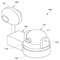
도 1은 본 발명의 일 실시예에 따른 전방위 감시 카메라 장치를 나타내는 사이도이다.
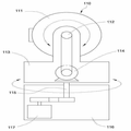
도 2는 도 1의 전방위 감시 카메라 장치의 주요 부분인 열감지카메라부의 회전 궤적을 나타내는 구성도이다.
도 3은 도 1의 전방위 감시 카메라 장치의 주요 부분인 열감지카메라부의 작동 상태를 나타내는 작동 상태도이다.
도 4는 도 1의 전방위 감시 카메라 장치의 주요 부분인 전방향카메라부의 구조를 나타내는 구성도이다.
도 5는 도 1의 전방위 감시 카메라 장치의 주요 부분인 제어부의 구성을 나타내는 구성도이다.BRIEF DESCRIPTION OF THE DRAWINGS FIG. 1 is a cross-sectional view of an omnidirectional monitoring camera apparatus according to an embodiment of the present invention.
FIG. 2 is a block diagram showing a rotation locus of a heat sensing camera unit, which is a main part of the omnidirectional monitoring camera apparatus of FIG. 1. FIG.
3 is an operational state diagram showing an operating state of the heat sensing camera unit which is a main part of the omnidirectional monitoring camera apparatus of FIG.
FIG. 4 is a block diagram showing the structure of an omnidirectional camera unit which is a main part of the omnidirectional monitoring camera apparatus of FIG. 1. FIG.
5 is a block diagram showing the configuration of a control unit which is a main part of the omnidirectional monitoring camera apparatus of Fig.
이하, 본 발명이 속하는 기술 분야에서 통상의 지식을 가진 자가 본 발명을 용이하게 실시할 수 있을 정도로 본 발명의 바람직한 실시예를 첨부된 도면을 참조하여 상세하게 설명하면 다음과 같다.DETAILED DESCRIPTION OF THE PREFERRED EMBODIMENTS Hereinafter, preferred embodiments of the present invention will be described in detail with reference to the accompanying drawings, so that those skilled in the art can easily carry out the present invention.
실시예를 설명함에 있어서 본 발명이 속하는 기술 분야에 익히 알려져 있고 본 발명과 직접적으로 관련이 없는 기술 내용에 대해서는 설명을 생략한다. 이는 불필요한 설명을 생략함으로써 본 발명의 요지를 흐리지 않고 더욱 명확히 전달하기 위함이다.In the following description of the embodiments of the present invention, descriptions of techniques which are well known in the technical field of the present invention and are not directly related to the present invention will be omitted. This is for the sake of clarity of the present invention without omitting the unnecessary explanation.
마찬가지 이유로 첨부 도면에 있어서 일부 구성요소는 과장되거나 생략되거나 개략적으로 도시되었다. 또한, 각 구성요소의 크기는 실제 크기를 전적으로 반영하는 것이 아니다. 각 도면에서 동일한 또는 대응하는 구성요소에는 동일한 참조 번호를 부여하였다.For the same reason, some of the components in the drawings are exaggerated, omitted, or schematically illustrated. Also, the size of each component does not entirely reflect the actual size. In the drawings, the same or corresponding components are denoted by the same reference numerals.
이하, 본 발명의 실시예들에 의하여 전방위 감시 카메라 장치를 설명하기 위한 도면들을 참고하여 본 발명에 대해 설명하도록 한다.Hereinafter, the present invention will be described with reference to the drawings for explaining an omnidirectional monitoring camera apparatus according to embodiments of the present invention.
도 1은 본 발명의 일 실시예에 따른 전방위 감시 카메라 장치를 나타내는 사이도이고, 도 2는 도 1의 전방위 감시 카메라 장치의 주요 부분인 열감지카메라부의 회전 궤적을 나타내는 구성도이며, 도 3은 도 1의 전방위 감시 카메라장치의 주요 부분인 열감지카메라부의 작동 상태를 나타내는 작동 상태도이고, 도 4는 도 1의 전방위 감시 카메라 장치의 주요 부분인 전방향카메라부의 구조를 나타내는 구성도이며, 도 5는 도 1의 전방위 감시 카메라 장치의 주요 부분인 제어부의 구성을 나타내는 구성도이다.FIG. 1 is a cross-sectional view showing an omnidirectional monitoring camera apparatus according to an embodiment of the present invention. FIG. 2 is a diagram showing a rotation locus of a thermal sensing camera unit, which is a main part of the omni- FIG. 4 is a configuration diagram showing the structure of an omnidirectional camera unit which is a main part of the omnidirectional monitoring camera apparatus of FIG. 1, and FIG. 5 Which is a main part of the omnidirectional monitoring camera apparatus of Fig. 1; Fig.
도 1 내지 도 5를 참고하면, 본 발명의 일 실시예에 따른 전방위 감시 카메라 장치(100)는 열감지를 실시하면서 교차 방향을 회전이동되는 열감지카메라부(110), 전방향카메라부(120), 및 제어부(130)를 포함한다.1 to 5, the omnidirectional
열감지카메라부(110)는 촬영대상지역 내에서 열을 감지하여 촬영을 실시하는 열감지카메라(111), 카메라회전축(112), 틸팅브라켓(113), 틸팅구동장치(114), 틸팅회전축(115), 회전브라켓(116), 및 회전구동장치(117)를 포함한다. The thermal
열감지카메라(111)는 촬영대상지역을 감시하기 위해서 설치되어 있으며, 촬영대상지역 내에 열화상을 촬영하도록 구비된다. 열감지카메라(111)는 촬영대상지역에 촬영되는 영상 내에서 열이 변화되는 열분포를 명도의 변화 또는 채도의 변화로 표시하여 표시된 부분으로 감지하도록 열화상을 촬영할 수 있다.The
열감지카메라(111)의 명도 변화와 채도 변화에 따른 열분포가 표시되는 상태에서 미리 설정된 온도 이상의 급격한 온도 변화가 발생되면 발생된 위치에서 명도 또는 채도가 급격하게 변화되도록 표시되고, 표시된 위치를 제어부(130)에서 인지할 수 있도록 촬영된 열화상을 전송할 수 있다. 제어부(130)는 전송받은 열화상에서 명도와 채도가 급격하게 변화되는 것을 화재 발생으로 인식하여 열감지 신호를 생성함과 동시에 열감지 위치가 열화상의 중앙에 위치하도록 열감지카메라(111)를 이동시킬 수 있다.When the temperature change of the
즉, 열감지카메라(111)는 열화상을 촬영함에 있어 제어부(130)가 상호 교차된 위치로 회전 이동하여 촬영되는 지역의 촬영되지 않는 사각을 최소화하면서 열화상을 촬영하고, 이동 촬영 중에 미리 설정된 온도 이상의 열변화가 발생되면 제어부(130)에서 이를 감지하여 열변화 지역이 촬영되는 화상의 중앙에 위치하도록 제어부(130)의 작동에 의해 이동되어 화재 지역을 감시하도록 촬영할 수 있다.In other words, the
즉, 열감지카메라(111)는 촬영대상지역을 이동하면서 감시를 실시하다가 화재 발생이나 외부 침입 등의 열변화 상황이 제어부(130)에서 감지되면 상황이 발생된 위치로 제어부(130)의 작동으로 이동하여 상황이 발생된 위치와 상황의 진행 상태를 지속적으로 모니터링하도록 촬영을 실시한다.That is, when the
특히, 산악이나 건물 내부에서 화재가 발생하게 되면 확산되는 속도가 빨라 진화가 어려움에 따라 열감지에 의해 화재가 발생되는 진원지를 신속하게 파악하고, 진원지의 정보를 촬영된 영상으로 전송하여 진원지의 위치와 유류에 의한 방화, 자연 발화, 담뱃불과 같은 실화 등의 화재의 종류에 대한 정보를 파악하여 화재의 진화 시에 효율적으로 진화를 실시할 수 있다.Particularly, when a fire occurs in a mountain or a building, the speed of spreading is so fast that it is difficult to evolve. Therefore, it is possible to quickly identify the epicenter where a fire occurs due to heat sensing, transmit information of the epicenter to the captured image, And information on the kinds of fires such as oil spill, spontaneous ignition, and cigarette misfire can be grasped and it can be evolved efficiently in the evolution of fire.
즉, 화재는 발화시키는 물질과 타는 물질의 종류에 따라 다른 종류의 소화기를 사용하여야하고, 화재의 진원지의 정보 없이 진화를 실시하게 되면 효율적인 진화가 어려움에 따라 진화를 위해서는 진원지의 위치와 화재의 종류를 정확하게 파악하는 것이 중요하다. 이에 따라, 열감지카메라(111)로 촬영대상지역을 감시하다가 화재에 의해 열변화가 감지되면 그 지역을 촬영하여 화재의 발화 위치와 화재의 종류에 대한 정보를 제공함에 따라 화재를 조기 진화하고, 확산을 방지할 수 있다.In other words, fire must use different types of fire extinguishers depending on the kind of burning substance and burning material, and if it is evolved without information of the source of fire, it is difficult to evolve efficiently. It is important to know exactly. Accordingly, if a thermal change is detected by a fire while monitoring an area to be photographed by the
카메라회전축(112)은 열감지카메라(111)의 양측면에 돌출되어 있으며, 열감지카메라(111)가 상하 방향으로 함께 회전되도록 구비된다. 카메라회전축(112)은 열감지카메라(111)의 상하 방향으로 회전되는 중심 위치에 돌출되어 열감지카메라(111)를 상하 방향으로 회전시키는 축 형태로 구비된다. 카메라회전축(112)을 회전하게 되면 열감지카메라(111)가 상하방향으로 회전되면서 감시 영역을 확장시킬 수 있다.The
틸팅브라켓(113)은 열감지카메라(111)의 양측면에서 하부 방향으로 구비되어 있으며, 카메라회전축(112)이 삽입되어 회전 가능하게 지지된다. 틸팅브라켓(113)은 열감지카메라(111)에 양측면과 하부에 위치하여 열감지카메라(111)를 상하방향으로 회전시키기 위해서 돌출 구비된 카메라회전축(112)이 회전 가능하게 지지되도록 설치된다.The
틸팅구동장치(114)는 틸팅브라켓(113)의 내부에 설치되어 있으며, 카메라회전축(112)을 회전시키도록 연결되어 작동에 의해 열감지카메라(111)를 상하 방향으로 회전시키는 동력을 제공하도록 구비된다. 틸팅구동장치(114)는 틸팅브라켓(113)의 내부에 회전 가능하게 삽입 지지된 카메라회전축(112)을 회전시키도록 연결되어 작동에 의해 카메라회전축(112)을 상하 방향으로 회전시키도록 설치된다.The
틸팅구동장치(114)는 축형태의 카메라회전축(112)에 연결되어 작동에 의해 회전시킬 수 있는 모든 수단이 포함될 수 있는 것으로, 통상적인 회전수단이 사용됨에 따라 상세한 설명을 생략한다.The
틸팅회전축(115)은 틸팅브라켓(113)의 하부에 돌출되어 있으며, 틸팅브라켓(113)을 상하와 교차되는 좌우 방향으로 함께 회전되도록 돌출되도록 구비된다. 틸팅회전축(115)은 열감지카메라(111)가 상하방향으로 회전작동되도록 지지된 틸팅브라켓(113)을 상하 방향과 교차되는 좌우 방향으로 회전시키는 중심축 형태로 하부 방향으로 돌출 구비된다.The tilting
회전브라켓(116)은 틸팅브라켓(113)의 하부에 배치되어 있으며, 틸팅회전축(115)이 삽입되어 좌우방향으로 회전 가능하게 지지되도록 설치된다. 회전브라켓(116)은 틸팅브라켓(113)의 하부에 위치하여 틸팅회전축(115)이 좌우 방향이 회전 가능하게 지지됨에 따라 틸팅구동장치(114)의 작동에 의해 상하 방향으로 회전되는 열감지카메라(111)를 틸팅브라켓(113)과 함께 좌우 방향으로 회전될 수 있도록 틸팅회전축(115)을 회전 가능하게 지지되도록 구비된다.The
회전구동장치(117)는 회전브라켓(116)의 내부에 배치되어 있으며, 틸팅회전축(115)을 회전시키도록 연결되어 작동에 의해 틸팅구동장치(114)의 작동으로 열감지카메라(111)가 회전되는 상하방향과 교차되는 좌우 방향으로 틸팅회전축(115)을 회전시키는 동력을 제공하도록 구비된다. 회전구동장치(117)는 회전브라켓(116)의 내부에 회전 가능하게 삽입 지지된 틸팅회전축(115)과 연결되도록 설치되어 작동에 의해 틸팅회전축(115)을 회전시키면 열감지카메라(111)가 상하로 회전구동되도록 지지된 틸팅브라켓(113)을 상하 방향과 교차되는 좌우 방향으로 회전시키도록 구비된다.The
이와 같은, 틸팅구동장치(114)와 회전구동장치(117)는 각각 제어부(130)에 연결되어 제어 신호에 의해 상하 방향으로 각도를 조절하면서 좌우방향으로 회전됨에 따라 회전 궤적이 구형을 따라서 나선형상이 되도록 회전하면서 감시를 실시할 수 있다. 따라서, 열감지카메라(111)는 제어부(130)의 작동에 의해 상하좌우 전방위에 대해서 회전되는 궤적을 가지면서 감시를 실시함에 따라 사각을 최소화할 수 있어 감시의 정확성을 향상시킬 수 있다.The tilting
전방향카메라부(120)는 열감지카메라(111)의 일측에 배치된 카메라 하우징(121), 제 1 어안렌즈체(122), 제 1 이미지센서(123), 제 2 어안렌즈체(124), 및 제 2 이미지센서(125)를 포함한다.The
카메라하우징(121)은 열감지카메라(111)의 일측에서 서로 대칭되는 양측을 각각 촬영하도록 설치된다. 카메라하우징(121)은 열감지카메라(111)의 일측에서 서로 대칭되는 양쪽을 촬영하기 위해서 각각의 촬영수단이 설치된 상태에서 촬영을 실시하도록 양쪽으로 통공이 구비된다.The
제 1 어안렌즈체(122)는 카메라하우징(121)에 위치하며, 촬영 시에 제1 방향의 180도의 화각을 가지도록 설치된다. 제 1 어안렌즈체(122)는 서로 대칭방향 중에 한쪽의 방향으 제 1 방향으로 정의하고, 볼록 형태로 방위각과 고도각이 180도 범위의 화각을 가지는 렌즈 형태로 구비되어 제 1 방향의 넓은 범위를 촬영에 의해 감시하도록 구비된다. 제 1 어안렌즈체(122)는 카메라하우징(121)의 서로 대칭되는 양쪽 중 한쪽 방향으로 제 1 이미지센서(123)에 투영되는 이미지가 한쪽 방향을 향해서 180도의 화각을 가지도록 설치되어 카메라하우징(121)을 중심으로 한쪽 방향의 상부와 하부 및 한쪽 방향의 화상을 모두 촬영할 수 있도록 설치된다.The first
제 1 이미지센서(123)는 제 1 어안렌즈체(122)를 통해 제1 방향으로 화상을 촬영하고, 촬영된 화상을 이미지로 저장하여 제어부(130)로 전송하도록 설치된다. 제 1 이미지센서(123)는 제 1 어안렌즈체(122)에서 투영된 화상을 전기적 신호로 변경하여 제어부(130)로 송신하도록 설치된다.The
제 2 어안렌즈체(124)는 카메라하우징에 위치하며, 촬영 시에 제1방향과 반대 방향의 180도의 화각을 가지도록 구비된다. 제 2 어안렌즈체(124)는 제 1 방향과 반대방향으로 볼록 형태로 방위각과 고도각이 180도 범위의 화각을 가지는 렌즈 형태로 구비되어 제 1 방향과 반대 방향의 넓은 범위를 촬영에 의해 감시하도록 구비된다. 제 2 어안렌즈체(125)는 카메라하우징(121)의 서로 대칭되는 양쪽 중 한쪽 방향과 반대 방향인 다른쪽 방향으로 제 2 이미지센서(125)에 투영되는 이미지가 한쪽 방향을 향해서 180도의 화각을 가지도록 설치되어 카메라하우징(121)을 중심으로 다른쪽 방향의 상부와 하부 및 다른쪽 방향의 화상을 모두 촬영할 수 있도록 설치된다.The second
제 2 이미지센서(125)는 제 2 어안렌즈체(124)를 통해 제1 방향의 반대 방향으로 화상을 촬영하고, 촬영된 화상을 이미지로 저장하여 제어부(130)로 전송하도록 설치된다. 제 2 이미지센서(123)는 제 1 어안렌즈체(122)에서 투영된 화상을 전기적 신호로 변경하여 제어부(130)로 송신하도록 설치된다.The
여기서, 제 1 어안렌즈체(122)와 제 2 어안렌즈체(124)는 서로 대칭되는 방향에서 각각 180도의 화각을 가지고 촬영됨에 따라 전체적으로 방위각과 고도각이 360도의 전방향으로 촬영하면서 감시할 수 있다. 즉, 전방향카메라부(120)는 서로 대칭되는 양쪽 방향에 각각 어안렌즈(122, 124)를 통해서 각각의 방향에서 고도각과 방위각이 180도 범위로 촬영하게 되면 전체적으로 360도 전방향으로 촬영하게 됨에 따라 촬영되는 범위를 확대시킬 수 있다.Since the first and second
즉, 전방향카메라부(120)는 열감지카메라부(110)에서 열변화를 감지하여 촬영을 실시할 때 주변 지역을 전방향에서 촬영하여 열변화된 위치의 주변을 지속적으로 감시할 수 있어 효율적 감시가 가능하다.That is, the
특히, 화재가 발생되었을 때에 화재 지역뿐만 아니라 주변에 사람이나 동물을 발견하여 대피시킬 수 있고, 화재 발생 후에 전파되는 방향을 인지하여 효과적으로 진화할 수 있다. 또한, 방화, 자연발화, 실화등의 발화 원인을 주변 상황 촬영에 의해 추적하고, 발화되는 원인 물질에 따라 진화계획을 수립하여 조기 진화를 실현할 수 있다. 그리고, 화재가 발생된 지역에서 인접한 위치에 인화물질 이나 위험 물질들이 있는지 확인 제거하여 화재의 확산을 최소화할 수 있다.In particular, when a fire occurs, people or animals can be found not only in the fire area but also in the vicinity, and can evacuate effectively after recognizing the direction of propagation after the fire occurs. In addition, the cause of ignition such as fire, spontaneous ignition, and misfire can be tracked by shooting the surrounding situation, and an evolutionary plan can be established in accordance with the causative substance to realize early evolution. In addition, it is possible to minimize the spread of fire by identifying and eliminating flammable or hazardous materials in adjacent locations in the area where the fire occurred.
아울러, 전방향카메라부(120)가 열감지카메라부(110)로 열변화를 감시하고 있는 설정된 영역을 전체적으로 감시하고 있어 열변화되는 상황의 전후를 파악할 수 있음에 따라 열감지카메라부(110)의 오작동이나 고장을 전방향의 촬영영상에 의해 인지할 수 있어 오작동과 고장에 의해 감시되지 않는 시간을 최소화할 수 있음으로써, 감시 효율이 향상될 수 있다.In addition, since the
제어부(130)는 틸팅구동장치(114)와 회전구동장치(117)의 작동을 제어하는 열감지제어부(131), 영상수신부(132), 및 영상처리부(133)를 포함한다.The
열감지제어부(131)는 틸팅구동장치(114)와 회전구동장치(117)에 각각 연결되어 있으며, 틸팅구동장치(114)의 작동에 의해 열감지카메라(111)의 상하 방향 각도를 조절하면서 회전구동장치(117)의 작동에 의해 열감지카메라(111)가 좌우 방향으로 회전되도록 제어하고, 열감지카메라(111)에서 열변화가 감지되어 생성된 열감지신호를 수신하여 열변화 위치가 화상의 중심에 위치하도록 틸팅구동장치(114)와 회전구동장치(117)를 작동시켜 열감지카메라(111)가 이동되도록 제어한다. 열감지제어부(131)는 열감지카메라(111)의 회전 궤적이 구형상의 내부에서 나선형태가 되도록 회전을 제어하여 열감지카메라(111)가 이동 시에 사각을 최소화하여 열감지 효율을 향상시킬 수 있다. 또한, 열감지카메라(111)가 이동 중에 열변화가 감지되면 회전 각도를 조절하여 열변화된 위치가 화상의 중심에 위치하도록 이동제어할 수 있다. 여기서, 열감지카메라에서 촬영된 열화상에서 미리 설정된 온도 이상의 열변화가 감지되면 열변화 지역으로 이동함과 동시에 열감지신호를 생성한다. 열감지신호는 감시자에게 열변화 상황을 알리는 수단이 사용될 수 있는 것으로, 경광등, 부저, 알람 등의 통상의 장치가 사용될 수 있음은 당업자에게 자명하다.The thermal
영상수신부(132)는 열감지카메라(111)와 제 1 이미지센서(122), 및 제 2 이미지센서(124)에 전기적으로 연결되어 열감지카메라(111)와 제 1 이미지센서(122), 및 제 2 이미지센서로(124)부터 영상을 수신하기 위하여 구비된다. 영상 수신부(132)는 열감지제어부(131)의 제어 신호에 따라 수직방향과 수평방향으로 교차 회전되면서 촬영대상지역을 촬영하는 열감지카메라(111)의 촬영 영상을 수신받고, 열감지카메라(111)에서 열이 감지되면 열감지신호에 따라 열감지제어부(131)의 작동으로 열감지 위치가 화상의 중앙에 위치하도록 이동되어 촬영되는 신호를 수신받도록 구비된다. 또한, 영상수신부(132)는 제 1 이미지센서(123)에서 제 1 방향으로 촬영된 영상신호를 수신하고, 제 2 이미지센서(125)에서 제 1 방향과 반대방향으로 촬영된 영상신호를 수신하여 영상처리부로 송신하도록 구비된다. 즉, 영상수신부(132)는 열감지카메라(111)에서 촬영되는 열화상 신호와 열변화가 발생된 지역이 중심에 위치하는 화상 신호, 제 1 이미지센서(123)에서 촬상된 제 1 방향의 화상 신호, 및 제 2 이미지센서(125)에서 촬상된 제 1 방향과 반대 방향의 화상 신호를 수신하여 영상처리부(133)로 송신하도록 구비된다.The
영상처리부(133)는 영상수신부(132)와 전기적으로 연결되어 있으며, 영상수신부에서 수신된 열감지카메라부(110)와 전방향카메라부(120)로부터의 열감지 영상 및 전방향 영상을 처리하여 출력하도록 구비된다. 영상처리부(133)는 열감지카메라부(110)에서 열화상 영상과 열이 감지되어 중앙에 위치하는 열감지 영상을 출력하여 촬영대상지역의 열 변화를 지속적으로 감시할 수 있다. 또한, 영상처리부(132)는 제 1 이미지센서(124)에 촬영된 제 1 방향의 180도 영상과 제 2 이미지센서에서 촬영된 제 1 방향과 반대 방향의 180도 영상을 하나의 360도 영상으로 합하여 전고도각과 전방위각의 전 방향이 촬영된 영상을 출력할 수 있다. 따라서, 열감지카메라부에서 열분포와 열변화를 감시하는 영상과, 전방향카메라부의 한쌍으로 촬영된 영상을 합하여 촬영대상지역의 전방위각과 전고도각의 360도 영상을 주변영상을 각각 사용자가 확인하여 화재 발생 또는 침입자의 침입을 열감지로 감시하면서 주변 상황에 따라 원인 및 진행상황을 지속적으로 감시할 수 있어 감시 효율을 향상시킬 수 있다.The
한편, 본 명세서와 도면에는 본 발명의 바람직한 실시예에 대하여 개시하였으며, 비록 특정 용어들이 사용되었으나, 이는 단지 본 발명의 기술 내용을 쉽게 설명하고 발명의 이해를 돕기 위한 일반적인 의미에서 사용된 것이지, 본 발명의 범위를 한정하고자 하는 것은 아니다. 여기에 개시된 실시예 외에도 본 발명의 기술적 사상에 바탕을 둔 다른 변형예들이 실시 가능하다는 것은 본 발명이 속하는 기술 분야에서 통상의 지식을 가진 자에게 자명한 것이다.While the present invention has been particularly shown and described with reference to exemplary embodiments thereof, it is to be understood that the invention is not limited to the disclosed embodiments, but, on the contrary, And is not intended to limit the scope of the invention. It is to be understood by those skilled in the art that other modifications based on the technical idea of the present invention are possible in addition to the embodiments disclosed herein.
100 : 감시 카메라 장치
110 : 열감지카메라부
111 : 열감지 카메라
112 : 카메라회전축
113 : 틸팅브라켓
114 : 틸팅구동장치
115 : 틸팅회전축
116 : 회전브라켓
117 : 회전구동장치
120 : 전방향카메라
121 : 카메라하우징
122 : 제 1 어안렌즈체
123 : 제 1 이미지센서
124 : 제 2 어안렌즈체
125 : 제 2 이미지센서
130 : 제어부
131 : 열감지제어부
132 : 영상수신부
133 : 영상처리부100: surveillance camera device 110: thermal sensing camera part
111: Thermal sensing camera 112: Camera rotation axis
113: tilting bracket 114: tilting drive device
115: tilting rotary shaft 116: rotary bracket
117: rotation driving device 120: omnidirectional camera
121: camera housing 122: first fisheye lens body
123: first image sensor 124: second fisheye lens body
125: second image sensor 130:
131: thermal sensing control unit 132: image receiving unit
133:
Claims (4)
상기 열감지카메라부의 일측에 배치되어 있으며, 중앙을 기준으로 서로 대칭이 되는 다른 방향에 한쌍으로 상호 촬영되는 화각을 방위각과 고도각이 서로 다른방향에서 각각 촬영될 수 있도록 구비하여 전방향에 대한 촬영이 가능한 전방향카메라부, 및
상기 열감지카메라부의 회전 작동과 열감지 작동을 제어하고, 상기 열감지카메라부와 상기 전방향카메라부에서 취득한 영상을 수신하여 열감지 영상 및 전방향영상을 출력하는 제어부를 포함하는 전방위 감시 카메라 장치.A thermal sensing camera unit configured to photograph a thermal image of a region to be photographed and to rotate at a predetermined angle set in a vertical direction and a horizontal direction,
Sensing camera unit, and the angle of view, which is mutually photographed in a pair of different directions symmetrical with respect to the center, can be photographed in different azimuth angles and elevation angles, A possible omnidirectional camera part, and
An omnidirectional surveillance camera unit including a thermal sensing camera unit and a control unit for receiving an image captured by the omnidirectional camera unit and outputting a thermal sensed image and an omnidirectional image, .
상기 열감지카메라부는,
촬영 대상 지역에 대한 열화상을 촬영하기 위한 열감지카메라,
상기 열감지카메라가 상하 방향으로 함께 회전되도록 돌출 구비된 카메라회전축,
상기 카메라회전축이 삽입되어 상하 방향으로 회전 가능하게 지지된 틸팅브라켓,
상기 카메라회전축을 회전시키도록 연결되어 작동에 의해 상기 열감지카메라를 상하 방향으로 회전시키는 동력을 제공하는 틸팅구동장치,
상기 틸팅브라켓을 상하와 교차되는 좌우 방향으로 함께 회전되도록 돌출된 틸팅회전축,
상기 틸팅회전축이 삽입되어 좌우 방향으로 회전가능하게 지지되어 있는 회전브라켓, 및
상기 틸팅회전축을 회전시키도록 연결되어 작동에 의해 상기 틸팅구동장치의 작동으로 상기 열감지카메라가 회전되는 상하방향과 교차되는 좌우 방향으로 상기틸팅회전축을 회전시키는 동력을 제공하는 회전구동장치를 포함하고,
상기 틸팅구동장치와 상기 회전구동장치는 각각 상기 제어부에 연결되어 제어 신호에 의해 상하 방향으로 각도를 조절하면서 좌우방향으로 회전됨에 따라 회전 궤적이 구형상의 내부에서 나선형태가 되도록 회전하면서 감시를 실시하는
전방위 감시 카메라 장치.The method according to claim 1,
The thermal sensing camera unit includes:
A thermal sensing camera for capturing thermal images of the area to be photographed,
A camera rotation axis provided so as to protrude so that the thermal sensing camera is rotated together in the vertical direction,
A tilting bracket inserted into the camera rotation shaft and rotatably supported in a vertical direction,
A tilting drive device connected to rotate the camera rotation shaft to provide power for rotating the thermal camera in the vertical direction by operation,
A tilting bracket rotatably supported by the tilting bracket,
A rotation bracket inserted into the tilting rotary shaft and rotatably supported in the left and right direction,
And a rotation driving device connected to rotate the tilting rotary shaft to provide power for rotating the tilting rotary shaft in a left-right direction intersecting the vertical direction in which the thermal sensing camera is rotated by operation of the tilting drive device ,
The tilting drive apparatus and the rotation drive apparatus are respectively connected to the control unit and are controlled so as to rotate in a horizontal direction while adjusting the angle in a vertical direction by a control signal,
Omnidirectional surveillance camera device.
상기 전방향 카메라는,
상기 열감지카메라부의 일측에 배치되어 있으며, 서로 대칭되는 양측에 각각 촬영되는 수단이 설치되도록 구비된 카메라하우징,
상기 카메라하우징에 배치되며, 촬영 시에 제1 방향의 180도의 화각을 가지는 제 1 어안렌즈체,
상기 제 1 어안렌즈체를 통해 촬영된 화상을 상기 제어부로 전송하는 제 1 이미지센서,
상기 카메라하우징에 배치되며, 촬영 시에 상기 제1 방향과 반대 방향의 180도의 화각을 가지는 제 2 어안렌즈체, 및
상기 제 2 어안렌즈체를 통해 촬영된 영상을 상기 제어부로 전송하는 제 2 이미지센서를 포함하는,
전방위 감시 카메라 장치.The method according to claim 1,
The omni-directional camera comprises:
A camera housing disposed on one side of the heat sensing camera and provided with means for photographing on both sides symmetrical to each other,
A first fisheye lens body disposed in the camera housing and having an angle of view of 180 degrees in a first direction at the time of shooting,
A first image sensor for transmitting an image photographed through the first fisheye lens body to the control unit,
A second fisheye lens body disposed in the camera housing and having an angle of view of 180 degrees opposite to the first direction at the time of shooting,
And a second image sensor for transmitting an image photographed through the second fisheye lens body to the control unit.
Omnidirectional surveillance camera device.
상기 제어부는,
상기 열감지카메라부의 상하 및 좌우 방향으로의 회전을 제어하고, 상기 열감지카메라부에서 수신한 열화상에서 미리 설정된 온도 이상의 열변화가 감지되면 열감지 신호를 생성하고, 상기 열감지카메라부를 상기 열변화가 감지되는 위치가 상기 열화상의 중앙에 위치하도록 제어하는 열감지제어부,
상기 열감지카메라부 및 상기 전방향카메라부와 전기적으로 연결되어 상기 열감지카메라부 및 상기 전방향카메라부로부터 영상을 수신하기 위한 영상수신부, 및
상기 영상수신부에서 수신된 상기 열감지 영상 및 상기 전방향 영상을 처리하여 영상처리부를 포함하는,
전방위 감시 카메라 장치.The method according to claim 1,
Wherein,
Wherein the control unit controls the rotation of the thermal sensing camera unit in the vertical and horizontal directions and generates a thermal sensed signal when a thermal change of a predetermined temperature or more is detected in the thermal deterioration image received by the thermal sensing camera unit, A heat sensing control unit for controlling the position of the sensing unit to be located at the center of the deterioration image,
An image receiving unit electrically connected to the heat sensing camera unit and the omnidirectional camera unit to receive images from the heat sensing camera unit and the omnidirectional camera unit,
And an image processing unit for processing the heat sensing image and the omnidirectional image received by the image receiving unit,
Omnidirectional surveillance camera device.
Priority Applications (1)
| Application Number | Priority Date | Filing Date | Title |
|---|---|---|---|
| KR1020170077553A KR20170077850A (en) | 2017-06-19 | 2017-06-19 | Apparatus of omnidirectional monitoring camera |
Applications Claiming Priority (1)
| Application Number | Priority Date | Filing Date | Title |
|---|---|---|---|
| KR1020170077553A KR20170077850A (en) | 2017-06-19 | 2017-06-19 | Apparatus of omnidirectional monitoring camera |
Related Parent Applications (1)
| Application Number | Title | Priority Date | Filing Date |
|---|---|---|---|
| KR1020150144284A Division KR20170044505A (en) | 2015-10-15 | 2015-10-15 | Apparatus of omnidirectional monitoring camera |
Publications (1)
| Publication Number | Publication Date |
|---|---|
| KR20170077850A true KR20170077850A (en) | 2017-07-06 |
Family
ID=59354098
Family Applications (1)
| Application Number | Title | Priority Date | Filing Date |
|---|---|---|---|
| KR1020170077553A Ceased KR20170077850A (en) | 2017-06-19 | 2017-06-19 | Apparatus of omnidirectional monitoring camera |
Country Status (1)
| Country | Link |
|---|---|
| KR (1) | KR20170077850A (en) |
Cited By (2)
| Publication number | Priority date | Publication date | Assignee | Title |
|---|---|---|---|---|
| KR101956125B1 (en) * | 2017-12-06 | 2019-03-12 | (주)스마트테크놀로지 | Fire sign detection system |
| KR20250027932A (en) * | 2023-08-21 | 2025-02-28 | 정선범 | Exterior Vehicle Camera Lens Cleaning System |
-
2017
- 2017-06-19 KR KR1020170077553A patent/KR20170077850A/en not_active Ceased
Cited By (2)
| Publication number | Priority date | Publication date | Assignee | Title |
|---|---|---|---|---|
| KR101956125B1 (en) * | 2017-12-06 | 2019-03-12 | (주)스마트테크놀로지 | Fire sign detection system |
| KR20250027932A (en) * | 2023-08-21 | 2025-02-28 | 정선범 | Exterior Vehicle Camera Lens Cleaning System |
Similar Documents
| Publication | Publication Date | Title |
|---|---|---|
| TWI645885B (en) | Movable intelligent fire extinguishing device | |
| ES2263797T3 (en) | DEPLOYABLE SURVEILLANCE DEVICE, PROVIDED WITH ACCOMMODATION WITH AUTOMATIC ENDORSEMENT, AND ASSOCIATED METHOD. | |
| KR101634337B1 (en) | Apparatus for Detecting and Extinguishing the Fire | |
| KR101508290B1 (en) | Day-night vision machine and water monitoring system thereof | |
| CN115623055A (en) | Telecommunication method, telecommunication system and autonomous mobile device | |
| KR101717579B1 (en) | System for detecting and suppressing of fire | |
| KR20170044451A (en) | System and Method for Controlling Remote Camera using Head mount display | |
| KR100865129B1 (en) | Forest fire monitoring terminal and forest fire monitoring system using the terminal | |
| CN111899447A (en) | Monitoring system and method | |
| KR101798372B1 (en) | system and method for detecting a fire | |
| KR20170077850A (en) | Apparatus of omnidirectional monitoring camera | |
| KR20170044505A (en) | Apparatus of omnidirectional monitoring camera | |
| KR101648292B1 (en) | Unmanned monitoring system apparatus | |
| KR101438731B1 (en) | Closed circuit television having improved performance of waterproof and shock absorbing | |
| KR101407549B1 (en) | Closed circuit television | |
| KR100614840B1 (en) | 360 ° panoramic camera device | |
| KR101738514B1 (en) | Monitoring system employing fish-eye thermal imaging camera and monitoring method using the same | |
| KR101305990B1 (en) | Closed circuit television | |
| KR20230104786A (en) | Firefighting drone with thermal imaging camera | |
| KR101619956B1 (en) | Apparatus for image processing of surveilance camera by using auto multi-tracing | |
| KR102173732B1 (en) | A remote camera control apparatus using a head mounted display | |
| KR20250095870A (en) | Robot for performing fire monitoring and fire suppression | |
| KR102598630B1 (en) | Object tracking pan-tilt apparatus based on ultra-wide camera and its operation method | |
| JP2005077279A (en) | Smoke detection system | |
| JP4535919B2 (en) | Surveillance system, surveillance camera, and controller |
Legal Events
| Date | Code | Title | Description |
|---|---|---|---|
| A107 | Divisional application of patent | ||
| PA0107 | Divisional application |
Comment text: Divisional Application of Patent Patent event date: 20170619 Patent event code: PA01071R01D Filing date: 20151015 Application number text: 1020150144284 |
|
| A201 | Request for examination | ||
| PA0201 | Request for examination |
Patent event code: PA02012R01D Patent event date: 20170622 Comment text: Request for Examination of Application Patent event code: PA02011R04I Patent event date: 20170619 Comment text: Divisional Application of Patent |
|
| PG1501 | Laying open of application | ||
| E902 | Notification of reason for refusal | ||
| PE0902 | Notice of grounds for rejection |
Comment text: Notification of reason for refusal Patent event date: 20170710 Patent event code: PE09021S01D |
|
| E90F | Notification of reason for final refusal | ||
| PE0902 | Notice of grounds for rejection |
Comment text: Final Notice of Reason for Refusal Patent event date: 20180319 Patent event code: PE09021S02D |
|
| E601 | Decision to refuse application | ||
| PE0601 | Decision on rejection of patent |
Patent event date: 20180901 Comment text: Decision to Refuse Application Patent event code: PE06012S01D Patent event date: 20180319 Comment text: Final Notice of Reason for Refusal Patent event code: PE06011S02I Patent event date: 20170710 Comment text: Notification of reason for refusal Patent event code: PE06011S01I |