KR20170077897A - Fuel cell stack having open flow passage - Google Patents
Fuel cell stack having open flow passage Download PDFInfo
- Publication number
- KR20170077897A KR20170077897A KR1020150187350A KR20150187350A KR20170077897A KR 20170077897 A KR20170077897 A KR 20170077897A KR 1020150187350 A KR1020150187350 A KR 1020150187350A KR 20150187350 A KR20150187350 A KR 20150187350A KR 20170077897 A KR20170077897 A KR 20170077897A
- Authority
- KR
- South Korea
- Prior art keywords
- diffusion layer
- gas diffusion
- fuel cell
- gasket
- flow path
- Prior art date
- Legal status (The legal status is an assumption and is not a legal conclusion. Google has not performed a legal analysis and makes no representation as to the accuracy of the status listed.)
- Ceased
Links
- 239000000446 fuel Substances 0.000 title claims abstract description 88
- 239000012528 membrane Substances 0.000 claims abstract description 45
- 239000007789 gas Substances 0.000 claims abstract description 42
- 238000009792 diffusion process Methods 0.000 claims abstract description 41
- 238000000926 separation method Methods 0.000 claims abstract description 36
- 239000001257 hydrogen Substances 0.000 claims abstract description 27
- 229910052739 hydrogen Inorganic materials 0.000 claims abstract description 27
- 238000001816 cooling Methods 0.000 claims abstract description 24
- UFHFLCQGNIYNRP-UHFFFAOYSA-N Hydrogen Chemical compound [H][H] UFHFLCQGNIYNRP-UHFFFAOYSA-N 0.000 claims abstract description 23
- QVGXLLKOCUKJST-UHFFFAOYSA-N atomic oxygen Chemical compound [O] QVGXLLKOCUKJST-UHFFFAOYSA-N 0.000 claims abstract description 21
- 239000001301 oxygen Substances 0.000 claims abstract description 21
- 229910052760 oxygen Inorganic materials 0.000 claims abstract description 21
- 239000005518 polymer electrolyte Substances 0.000 claims abstract description 20
- 239000002131 composite material Substances 0.000 claims abstract description 10
- 238000002347 injection Methods 0.000 claims abstract description 10
- 239000007924 injection Substances 0.000 claims abstract description 10
- OKTJSMMVPCPJKN-UHFFFAOYSA-N Carbon Chemical compound [C] OKTJSMMVPCPJKN-UHFFFAOYSA-N 0.000 claims description 10
- 229910052799 carbon Inorganic materials 0.000 claims description 10
- 229920000642 polymer Polymers 0.000 claims description 10
- 238000000034 method Methods 0.000 claims description 9
- PXHVJJICTQNCMI-UHFFFAOYSA-N Nickel Chemical compound [Ni] PXHVJJICTQNCMI-UHFFFAOYSA-N 0.000 claims description 6
- BASFCYQUMIYNBI-UHFFFAOYSA-N platinum Chemical compound [Pt] BASFCYQUMIYNBI-UHFFFAOYSA-N 0.000 claims description 6
- XEEYBQQBJWHFJM-UHFFFAOYSA-N Iron Chemical compound [Fe] XEEYBQQBJWHFJM-UHFFFAOYSA-N 0.000 claims description 4
- KDLHZDBZIXYQEI-UHFFFAOYSA-N Palladium Chemical compound [Pd] KDLHZDBZIXYQEI-UHFFFAOYSA-N 0.000 claims description 4
- RTAQQCXQSZGOHL-UHFFFAOYSA-N Titanium Chemical compound [Ti] RTAQQCXQSZGOHL-UHFFFAOYSA-N 0.000 claims description 3
- 238000003475 lamination Methods 0.000 claims description 3
- 229910052759 nickel Inorganic materials 0.000 claims description 3
- 229910052697 platinum Inorganic materials 0.000 claims description 3
- 239000010936 titanium Substances 0.000 claims description 3
- 229910052719 titanium Inorganic materials 0.000 claims description 3
- HYZJCKYKOHLVJF-UHFFFAOYSA-N 1H-benzimidazole Chemical compound C1=CC=C2NC=NC2=C1 HYZJCKYKOHLVJF-UHFFFAOYSA-N 0.000 claims description 2
- 229910052684 Cerium Inorganic materials 0.000 claims description 2
- VYZAMTAEIAYCRO-UHFFFAOYSA-N Chromium Chemical compound [Cr] VYZAMTAEIAYCRO-UHFFFAOYSA-N 0.000 claims description 2
- YCKRFDGAMUMZLT-UHFFFAOYSA-N Fluorine atom Chemical compound [F] YCKRFDGAMUMZLT-UHFFFAOYSA-N 0.000 claims description 2
- 229920006275 Ketone-based polymer Polymers 0.000 claims description 2
- ZOKXTWBITQBERF-UHFFFAOYSA-N Molybdenum Chemical compound [Mo] ZOKXTWBITQBERF-UHFFFAOYSA-N 0.000 claims description 2
- KJTLSVCANCCWHF-UHFFFAOYSA-N Ruthenium Chemical compound [Ru] KJTLSVCANCCWHF-UHFFFAOYSA-N 0.000 claims description 2
- ATJFFYVFTNAWJD-UHFFFAOYSA-N Tin Chemical compound [Sn] ATJFFYVFTNAWJD-UHFFFAOYSA-N 0.000 claims description 2
- 150000001408 amides Chemical class 0.000 claims description 2
- 229910052804 chromium Inorganic materials 0.000 claims description 2
- 239000011651 chromium Substances 0.000 claims description 2
- 229910017052 cobalt Inorganic materials 0.000 claims description 2
- 239000010941 cobalt Substances 0.000 claims description 2
- GUTLYIVDDKVIGB-UHFFFAOYSA-N cobalt atom Chemical compound [Co] GUTLYIVDDKVIGB-UHFFFAOYSA-N 0.000 claims description 2
- 150000002148 esters Chemical class 0.000 claims description 2
- 239000004744 fabric Substances 0.000 claims description 2
- 239000011737 fluorine Substances 0.000 claims description 2
- 229910052731 fluorine Inorganic materials 0.000 claims description 2
- PCHJSUWPFVWCPO-UHFFFAOYSA-N gold Chemical compound [Au] PCHJSUWPFVWCPO-UHFFFAOYSA-N 0.000 claims description 2
- 229910052737 gold Inorganic materials 0.000 claims description 2
- 239000010931 gold Substances 0.000 claims description 2
- 150000003949 imides Chemical class 0.000 claims description 2
- 229910052742 iron Inorganic materials 0.000 claims description 2
- WPBNNNQJVZRUHP-UHFFFAOYSA-L manganese(2+);methyl n-[[2-(methoxycarbonylcarbamothioylamino)phenyl]carbamothioyl]carbamate;n-[2-(sulfidocarbothioylamino)ethyl]carbamodithioate Chemical compound [Mn+2].[S-]C(=S)NCCNC([S-])=S.COC(=O)NC(=S)NC1=CC=CC=C1NC(=S)NC(=O)OC WPBNNNQJVZRUHP-UHFFFAOYSA-L 0.000 claims description 2
- 229910052750 molybdenum Inorganic materials 0.000 claims description 2
- 239000011733 molybdenum Substances 0.000 claims description 2
- 229910052762 osmium Inorganic materials 0.000 claims description 2
- SYQBFIAQOQZEGI-UHFFFAOYSA-N osmium atom Chemical compound [Os] SYQBFIAQOQZEGI-UHFFFAOYSA-N 0.000 claims description 2
- 229910052763 palladium Inorganic materials 0.000 claims description 2
- 229910052707 ruthenium Inorganic materials 0.000 claims description 2
- 229910052718 tin Inorganic materials 0.000 claims description 2
- 239000011135 tin Substances 0.000 claims description 2
- WFKWXMTUELFFGS-UHFFFAOYSA-N tungsten Chemical compound [W] WFKWXMTUELFFGS-UHFFFAOYSA-N 0.000 claims description 2
- 229910052721 tungsten Inorganic materials 0.000 claims description 2
- 239000010937 tungsten Substances 0.000 claims description 2
- 229910052720 vanadium Inorganic materials 0.000 claims description 2
- GWXLDORMOJMVQZ-UHFFFAOYSA-N cerium Chemical compound [Ce] GWXLDORMOJMVQZ-UHFFFAOYSA-N 0.000 claims 1
- 229910052741 iridium Inorganic materials 0.000 claims 1
- GKOZUEZYRPOHIO-UHFFFAOYSA-N iridium atom Chemical compound [Ir] GKOZUEZYRPOHIO-UHFFFAOYSA-N 0.000 claims 1
- 229910052703 rhodium Inorganic materials 0.000 claims 1
- 239000010948 rhodium Substances 0.000 claims 1
- MHOVAHRLVXNVSD-UHFFFAOYSA-N rhodium atom Chemical compound [Rh] MHOVAHRLVXNVSD-UHFFFAOYSA-N 0.000 claims 1
- LEONUFNNVUYDNQ-UHFFFAOYSA-N vanadium atom Chemical compound [V] LEONUFNNVUYDNQ-UHFFFAOYSA-N 0.000 claims 1
- 238000004519 manufacturing process Methods 0.000 abstract description 8
- 229910052751 metal Inorganic materials 0.000 description 16
- 239000002184 metal Substances 0.000 description 16
- 239000000498 cooling water Substances 0.000 description 14
- 239000012495 reaction gas Substances 0.000 description 7
- -1 hydrogen ions Chemical class 0.000 description 6
- 238000006722 reduction reaction Methods 0.000 description 6
- 238000007254 oxidation reaction Methods 0.000 description 4
- XLYOFNOQVPJJNP-UHFFFAOYSA-N water Substances O XLYOFNOQVPJJNP-UHFFFAOYSA-N 0.000 description 4
- 239000003054 catalyst Substances 0.000 description 3
- MYMOFIZGZYHOMD-UHFFFAOYSA-N Dioxygen Chemical compound O=O MYMOFIZGZYHOMD-UHFFFAOYSA-N 0.000 description 2
- 239000000853 adhesive Substances 0.000 description 2
- 230000001070 adhesive effect Effects 0.000 description 2
- 239000000470 constituent Substances 0.000 description 2
- 229910001882 dioxygen Inorganic materials 0.000 description 2
- 238000003754 machining Methods 0.000 description 2
- 230000003647 oxidation Effects 0.000 description 2
- RYGMFSIKBFXOCR-UHFFFAOYSA-N Copper Chemical compound [Cu] RYGMFSIKBFXOCR-UHFFFAOYSA-N 0.000 description 1
- 229910045601 alloy Inorganic materials 0.000 description 1
- 239000000956 alloy Substances 0.000 description 1
- WYTGDNHDOZPMIW-RCBQFDQVSA-N alstonine Natural products C1=CC2=C3C=CC=CC3=NC2=C2N1C[C@H]1[C@H](C)OC=C(C(=O)OC)[C@H]1C2 WYTGDNHDOZPMIW-RCBQFDQVSA-N 0.000 description 1
- 229910052782 aluminium Inorganic materials 0.000 description 1
- XAGFODPZIPBFFR-UHFFFAOYSA-N aluminium Chemical compound [Al] XAGFODPZIPBFFR-UHFFFAOYSA-N 0.000 description 1
- 239000003575 carbonaceous material Substances 0.000 description 1
- ZMIGMASIKSOYAM-UHFFFAOYSA-N cerium Chemical compound [Ce][Ce][Ce][Ce][Ce][Ce][Ce][Ce][Ce][Ce][Ce][Ce][Ce][Ce][Ce][Ce][Ce][Ce][Ce][Ce][Ce][Ce][Ce][Ce][Ce][Ce][Ce][Ce][Ce][Ce][Ce][Ce][Ce][Ce][Ce][Ce][Ce][Ce] ZMIGMASIKSOYAM-UHFFFAOYSA-N 0.000 description 1
- 239000007795 chemical reaction product Substances 0.000 description 1
- 150000001875 compounds Chemical class 0.000 description 1
- 229910052802 copper Inorganic materials 0.000 description 1
- 239000010949 copper Substances 0.000 description 1
- 230000005611 electricity Effects 0.000 description 1
- 238000003487 electrochemical reaction Methods 0.000 description 1
- 238000010438 heat treatment Methods 0.000 description 1
- 150000002500 ions Chemical class 0.000 description 1
- 239000000463 material Substances 0.000 description 1
- 230000002093 peripheral effect Effects 0.000 description 1
- CFQCIHVMOFOCGH-UHFFFAOYSA-N platinum ruthenium Chemical compound [Ru].[Pt] CFQCIHVMOFOCGH-UHFFFAOYSA-N 0.000 description 1
- 238000010248 power generation Methods 0.000 description 1
- 238000003825 pressing Methods 0.000 description 1
- 239000011347 resin Substances 0.000 description 1
- 229920005989 resin Polymers 0.000 description 1
- 238000007789 sealing Methods 0.000 description 1
- 230000035939 shock Effects 0.000 description 1
- 239000010935 stainless steel Substances 0.000 description 1
- 229910001220 stainless steel Inorganic materials 0.000 description 1
- 239000000126 substance Substances 0.000 description 1
- GPPXJZIENCGNKB-UHFFFAOYSA-N vanadium Chemical compound [V]#[V] GPPXJZIENCGNKB-UHFFFAOYSA-N 0.000 description 1
Images




Classifications
-
- H—ELECTRICITY
- H01—ELECTRIC ELEMENTS
- H01M—PROCESSES OR MEANS, e.g. BATTERIES, FOR THE DIRECT CONVERSION OF CHEMICAL ENERGY INTO ELECTRICAL ENERGY
- H01M8/00—Fuel cells; Manufacture thereof
- H01M8/02—Details
- H01M8/0202—Collectors; Separators, e.g. bipolar separators; Interconnectors
- H01M8/0267—Collectors; Separators, e.g. bipolar separators; Interconnectors having heating or cooling means, e.g. heaters or coolant flow channels
-
- H—ELECTRICITY
- H01—ELECTRIC ELEMENTS
- H01M—PROCESSES OR MEANS, e.g. BATTERIES, FOR THE DIRECT CONVERSION OF CHEMICAL ENERGY INTO ELECTRICAL ENERGY
- H01M8/00—Fuel cells; Manufacture thereof
- H01M8/02—Details
- H01M8/0202—Collectors; Separators, e.g. bipolar separators; Interconnectors
- H01M8/0258—Collectors; Separators, e.g. bipolar separators; Interconnectors characterised by the configuration of channels, e.g. by the flow field of the reactant or coolant
-
- H—ELECTRICITY
- H01—ELECTRIC ELEMENTS
- H01M—PROCESSES OR MEANS, e.g. BATTERIES, FOR THE DIRECT CONVERSION OF CHEMICAL ENERGY INTO ELECTRICAL ENERGY
- H01M8/00—Fuel cells; Manufacture thereof
- H01M8/10—Fuel cells with solid electrolytes
- H01M8/1004—Fuel cells with solid electrolytes characterised by membrane-electrode assemblies [MEA]
-
- H—ELECTRICITY
- H01—ELECTRIC ELEMENTS
- H01M—PROCESSES OR MEANS, e.g. BATTERIES, FOR THE DIRECT CONVERSION OF CHEMICAL ENERGY INTO ELECTRICAL ENERGY
- H01M8/00—Fuel cells; Manufacture thereof
- H01M8/10—Fuel cells with solid electrolytes
- H01M8/1016—Fuel cells with solid electrolytes characterised by the electrolyte material
- H01M8/1018—Polymeric electrolyte materials
- H01M8/102—Polymeric electrolyte materials characterised by the chemical structure of the main chain of the ion-conducting polymer
-
- H—ELECTRICITY
- H01—ELECTRIC ELEMENTS
- H01M—PROCESSES OR MEANS, e.g. BATTERIES, FOR THE DIRECT CONVERSION OF CHEMICAL ENERGY INTO ELECTRICAL ENERGY
- H01M8/00—Fuel cells; Manufacture thereof
- H01M8/24—Grouping of fuel cells, e.g. stacking of fuel cells
- H01M8/2465—Details of groupings of fuel cells
-
- Y—GENERAL TAGGING OF NEW TECHNOLOGICAL DEVELOPMENTS; GENERAL TAGGING OF CROSS-SECTIONAL TECHNOLOGIES SPANNING OVER SEVERAL SECTIONS OF THE IPC; TECHNICAL SUBJECTS COVERED BY FORMER USPC CROSS-REFERENCE ART COLLECTIONS [XRACs] AND DIGESTS
- Y02—TECHNOLOGIES OR APPLICATIONS FOR MITIGATION OR ADAPTATION AGAINST CLIMATE CHANGE
- Y02E—REDUCTION OF GREENHOUSE GAS [GHG] EMISSIONS, RELATED TO ENERGY GENERATION, TRANSMISSION OR DISTRIBUTION
- Y02E60/00—Enabling technologies; Technologies with a potential or indirect contribution to GHG emissions mitigation
- Y02E60/30—Hydrogen technology
- Y02E60/50—Fuel cells
-
- Y02E60/521—
Landscapes
- Chemical & Material Sciences (AREA)
- Life Sciences & Earth Sciences (AREA)
- Engineering & Computer Science (AREA)
- Manufacturing & Machinery (AREA)
- Sustainable Development (AREA)
- Sustainable Energy (AREA)
- Chemical Kinetics & Catalysis (AREA)
- Electrochemistry (AREA)
- General Chemical & Material Sciences (AREA)
- Crystallography & Structural Chemistry (AREA)
- Fuel Cell (AREA)
Abstract
본 발명은 고분자 전해질막; 상기 고분자 전해질막의 일면에 형성된 애노드 전극; 및 상기 고분자 전해질막의 타면에 형성된 캐소드 전극;을 포함하는 막 전극 접합체(MEA;membrane electrode assembly); 상기 막 전극 접합체의 일면에 접하는 제1 가스 확산층; 상기 막 전극 접합체의 타면에 접하는 제2 가스 확산층; 상기 제1 가스 확산층 일면에 접하고, 일부가 요철 형태로 절곡되어 산소연료 주입과 공냉을 동시에 수행하는 복합 유로를 포함하는 캐소드 분리판; 상기 제2 가스 확산층 일면에 접하고 수소 유로가 형성된 애노드 분리판; 상기 캐소드 분리판의 복합 유로 상단 및 하단에 각각 위치하는 제1 가스켓; 및 제2 가스켓; 상기 애노드 분리판과 상기 제2 가스 확산층 사이에 위치하는 제3 가스켓;을 포함하는 연료전지를 제공한다. 또한, 본 발명의 일 실시 예에 따른 개방형 유로가 구비된 연료전지 스택은 산소연료 주입과 공냉을 동시에 수행 가능하고, 이에 연료전지에서 발생하는 열과 수분을 효율적으로 방출할 수 있으며, 간소화된 구조로 인해 경량화, 제조 비용 절감이 가능하다.The present invention relates to a polymer electrolyte membrane; An anode electrode formed on one surface of the polymer electrolyte membrane; And a cathode electrode formed on the other surface of the polymer electrolyte membrane, the membrane electrode assembly comprising: a membrane electrode assembly (MEA) A first gas diffusion layer in contact with one surface of the membrane electrode assembly; A second gas diffusion layer contacting the other surface of the membrane electrode assembly; A cathode separation plate including a composite flow path which is in contact with one surface of the first gas diffusion layer and is partially bent in a concavo-convex form to simultaneously perform oxygen fuel injection and air cooling; An anode separator which is in contact with one surface of the second gas diffusion layer and has a hydrogen flow path; A first gasket positioned at an upper end and a lower end of the multiple flow path of the cathode separation plate, respectively; And a second gasket; And a third gasket positioned between the anode separator and the second gas diffusion layer. In addition, the fuel cell stack having the open channel according to an embodiment of the present invention can simultaneously perform oxygen fuel injection and air cooling, and can efficiently discharge heat and moisture generated in the fuel cell, Thus making it possible to reduce the weight and manufacturing cost.
Description
본 발명은 개방형 유로가 구비된 연료전지 스택에 관한 것이다.The present invention relates to a fuel cell stack having an open channel.
연료전지는 수소 가스와 산소 가스를 이용하여 전기 화학적으로 전기를 생산하는 장치로서, 외부에서 연속적으로 공급되는 수소 및 공기를 전기화학 반응에 의하여 직접 전기에너지와 열에너지로 변환시키는 장치이다.A fuel cell is a device for producing electricity electrochemically using hydrogen gas and oxygen gas, and is a device for directly converting hydrogen and air continuously supplied from the outside into electric energy and thermal energy by electrochemical reaction.
이러한 연료전지는 산화전극에서의 산화반응 및 환원전극에서의 환원반응을 이용하여 전력을 생성하게 된다. 이때, 산화 및 환원 반응을 촉진시키기 위해 백금 또는 백금-루테늄 금속 등을 포함하는 촉매층과 고분자 전해질막으로 구성된 막-전극 접합체(MEA;membrane electrode assembly)가 사용되며 막-전극 접합체 양단으로 전도성 물질의 분리판이 체결되어 셀 구조를 이룬다.Such a fuel cell generates electric power by using an oxidation reaction at the oxidation electrode and a reduction reaction at the reduction electrode. At this time, a membrane electrode assembly (MEA) composed of a catalyst layer containing platinum or platinum-ruthenium metal and a polymer electrolyte membrane is used to promote the oxidation and reduction reaction, and a membrane electrode assembly The separation plate is fastened to form a cell structure.
연료전지의 단위 셀(unit cell)은 전압이 낮아 실용성이 떨어지기 때문에, 일반적으로 수개 내지 수백개의 단위 셀을 적층하여 스택(stack)으로 사용한다. 단위 셀의 적층 시, 각각의 단위 셀 간에 전기적 접속이 이루어지게 하고, 반응 가스를 분리시켜주는 역할을 하는 것이 금속 분리판이다. 일반적인 연료전지용 금속 분리판은 직사각형 형태의 금속판의 중심부에 반응가스 채널 및 냉각수 채널이 형성되고, 그 주변을 둘러싸는 가스켓이 형성된다. 반응가스 채널과 냉각수 채널을 포함하여 통상 채널부라 한다.Since a unit cell of a fuel cell is low in practicality due to low voltage, generally several to several hundred unit cells are stacked and used as a stack. When a unit cell is stacked, a metal separator plays a role of making electrical connection between each unit cell and separating the reaction gas. In a typical metallic separator for a fuel cell, a reaction gas channel and a cooling water channel are formed at the center of a rectangular metal plate, and a gasket surrounding the periphery of the reaction gas channel and the cooling water channel is formed. Including a reaction gas channel and a cooling water channel.
통상 반응가스 채널은 금속판의 전면에서 배면으로 스탬핑 공정에 의해 돌출되어 형성되고, 냉각수 채널은 금속판의 배면에 돌출된 반응가스 채널 사이의 영역을 활용하여 형성된다. 이렇게 형성된 채널부의 구조는 반응가스가 금속판의 전면 상에서 유동하고, 냉각수는 금속판의 배면 상에서 유동하도록 한다. 이러한 점에서 금속판의 전면을 반응가스 유동면으로, 금속판의 배면을 냉각수 유동면이라 지칭하기도 한다.Usually, the reaction gas channel is formed by protruding from the front surface of the metal plate to the back surface by a stamping process, and the cooling water channel is formed by utilizing a region between the reaction gas channels protruding from the back surface of the metal plate. The structure of the channel portion thus formed allows the reactive gas to flow on the front surface of the metal plate and the cooling water to flow on the back surface of the metal plate. In this respect, the front surface of the metal plate may be referred to as the reaction gas flow surface, and the back surface of the metal plate may be referred to as the cooling water flow surface.
이러한 구조를 갖는 금속 분리판은 수냉식(water-cooled) 금속 분리판 구조로서, 채널부 일측의 냉각수 유입 매니폴드로 유입되는 냉각수가 냉각수 채널을 통과하면서 연료전지 동작시 활성화 손실(activation loss), 양극에서의 환원 반응 및 줄 가열(joule heating) 등의 원인으로 인하여 발생하는 열을 냉각시킨다. 상기의 냉각과정을 거친 냉각수는, 이후 채널부 타측의 냉각수 배출 매니폴드를 통하여 분리판 외부로 빠져나간다.The metal separator having such a structure is a water-cooled metal separator plate. The cooling water flowing into the cooling water inlet manifold at one side of the channel portion passes through the cooling water channel, And the heat generated by the reduction reaction and the joule heating of the heat source is cooled. The cooling water having undergone the cooling process is then discharged to the outside of the separation plate through the cooling water discharge manifold on the other side of the channel portion.
이러한 수냉식 금속 분리판의 경우, 연료전지 동작시 발생하는 열을 냉각시키기 위하여, 냉각수를 금속 분리판에 지속적으로 공급해주어야 한다. 이 경우 냉각수 공급을 위한 펌프, 이온제거기, 열교환기 등의 장치가 필요하게 되며, 이로 인하여 연료전지 시스템 제조 비용의 상승을 초래하는 원인이 된다.In the case of such a water-cooled metal separator, in order to cool the heat generated during operation of the fuel cell, cooling water must be continuously supplied to the metal separator. In this case, a device for supplying cooling water, such as a pump, an ion eliminator, and a heat exchanger, is required, which causes a rise in manufacturing cost of the fuel cell system.
이에 반해, 종래의 공냉식 금속 분리판의 경우, 공기 공급을 위한 캐소드 분리판 1 장과, 원활한 공기 공급을 위한 수직 방향의 공간 확보 및 냉각 핀의 역할을 수행하는 냉각판 1 장, 총 2장으로 캐소드 층을 제작하고 있었으나, 이 경우 냉각판이 추가로 필요하기 때문에 연료전지 스택의 전체 부피 및 제조 비용을 증가시키는 문제가 있었다. 관련 선행문헌으로 공기냉각 구조를 갖는 냉각판이 단위전지 사이에 적층된 연료전지 스택에 대하여 기재되어 있다(대한민국 공개특허공보 제10-2003-0042633호).On the contrary, in the case of the conventional air-cooled metal separator, one cathode separator for air supply, one cooling plate for securing a space in the vertical direction for smooth air supply and serving as a cooling fin, However, in this case, since a cooling plate is additionally required, there is a problem of increasing the total volume of the fuel cell stack and manufacturing cost. Related Background Art [0002] A fuel cell stack in which a cooling plate having an air cooling structure is laminated between unit cells is disclosed in Korean Patent Publication No. 10-2003-0042633.
그런데, 종래의 연료 전지에서는 상기한 가스켓이 평평한 단면 형상을 가지면서 막-전극 접합체의 가장자리 부분에 단순히 압착되어 연결된다. 이때 연료전지의 체결시 분리판에 가해지는 가압력의 차이에 의하여 가스켓과 막-전극 접합체 사이에 틈새가 발생 될 수 있다. 이러한 틈새에 의하여 막-전극 접합체와 양 분리판 간의 기밀이 파괴됨에 따라 이 분리판을 통과하는 수소와 산소의 누설이 있을 수 있다. 따라서 연료전지의 정상적인 전기 출력이 어렵게 되고, 분리판을 통과하는 수소와 산소의 압력 저감으로 인해 연료 전지 성능이 저하됨은 물론, 수소와 산소의 누설로 인한 안전 사고를 초래할 우려가 있다.However, in the conventional fuel cell, the gasket is simply pressed and connected to the edge portion of the membrane-electrode assembly with a flat cross-sectional shape. At this time, a gap may be generated between the gasket and the membrane-electrode assembly due to the difference in the pressing force applied to the separator plate when the fuel cell is tightened. As the airtightness between the membrane electrode assembly and the separator plate is destroyed by the gap, hydrogen and oxygen may leak through the separator plate. Therefore, the normal electrical output of the fuel cell becomes difficult, and the fuel cell performance is deteriorated due to the reduction of the pressure of hydrogen and oxygen passing through the separator, and safety accidents due to leakage of hydrogen and oxygen may occur.
또한, 애노드 전극 또는 캐소드 전극의 촉매층과 가스 확산층에 접착제를 사용하여 막-전극 접합체를 제조하는 방법이 기재되어 있고(대한민국 공개특허공보 제2003-0094001호), 막-전극 접합체의 가장자리와 냉각수 이송 판(water transport plate)의 가장자리를 탄성 접착제로 접착시켜 밀폐성을 개선시킨 연료전지 스택이 기재되어 있으며(미국특허 6165634호), 카본 플레이트의 가스 누출을 방지하기 위하여 저점도의 수지를 함침, 저온 소성시킨 것에 대하여 기재하고 있으나(일본 특개평 9-55214호), 상기 밀폐 방법은 분리판과 막-전극 접합체의 압착시에 균일한 평면을 형성하지 못하여 연료전지 스택의 막-전극 접합체와 분리판 사이에서 수소와 산소의 누출이 발생하는 문제를 여전히 가지고 있다.In addition, a method of manufacturing a membrane-electrode assembly by using an adhesive for a catalyst layer and a gas diffusion layer of an anode electrode or a cathode electrode is disclosed (Korean Patent Laid-Open Publication No. 2003-0094001), and the edge of the membrane- (U.S. Patent No. 6,165,634) discloses a fuel cell stack in which the edge of a water transport plate is bonded with an elastic adhesive to improve airtightness (U.S. Patent No. 6,165,634). In order to prevent gas leakage of a carbon plate, a low viscosity resin is impregnated, (Japanese Unexamined Patent Publication No. 9-55214). However, this sealing method fails to form a uniform plane when the separator and the membrane-electrode assembly are squeezed, so that the membrane-electrode assembly of the fuel cell stack and the separator plate There is still a problem of leakage of hydrogen and oxygen from the gas.
본 발명의 목적은 경량화 및 간소화된 연료전지 스택을 제공하는 데 있다.It is an object of the present invention to provide a fuel cell stack that is lightweight and simplified.
상기 목적을 달성하기 위하여, 본 발명의 실시 예는In order to achieve the above object,
고분자 전해질막; 상기 고분자 전해질막의 일면에 형성된 애노드 전극; 및 상기 고분자 전해질막의 타면에 형성된 캐소드 전극;을 포함하는 막 전극 접합체(MEA;membrane electrode assembly);Polymer Electrolyte Membrane; An anode electrode formed on one surface of the polymer electrolyte membrane; And a cathode electrode formed on the other surface of the polymer electrolyte membrane, the membrane electrode assembly comprising: a membrane electrode assembly (MEA)
상기 막 전극 접합체의 일면에 접하는 제1 가스 확산층;A first gas diffusion layer in contact with one surface of the membrane electrode assembly;
상기 막 전극 접합체의 타면에 접하는 제2 가스 확산층;A second gas diffusion layer contacting the other surface of the membrane electrode assembly;
상기 제1 가스 확산층 일면에 접하고, 일부가 요철 형태로 절곡되어 산소연료 주입과 공냉을 동시에 수행하는 복합 유로를 포함하는 캐소드 분리판;A cathode separation plate including a composite flow path which is in contact with one surface of the first gas diffusion layer and is partially bent in a concavo-convex form to simultaneously perform oxygen fuel injection and air cooling;
상기 제2 가스 확산층 일면에 접하고 수소 유로가 형성된 애노드 분리판;An anode separator which is in contact with one surface of the second gas diffusion layer and has a hydrogen flow path;
상기 캐소드 분리판의 복합 유로 상단 및 하단에 각각 위치하는 제1 가스켓; 및 제2 가스켓;A first gasket positioned at an upper end and a lower end of the multiple flow path of the cathode separation plate, respectively; And a second gasket;
상기 애노드 분리판과 상기 제2 가스 확산층 사이에 위치하는 제3 가스켓;을 포함하는 연료전지를 제공한다.And a third gasket positioned between the anode separator and the second gas diffusion layer.
또한, 본 발명의 다른 실시 예는In another embodiment of the present invention,
상기의 연료전지를 적어도 2개 이상 포함하고, 상기 연료전지를 적층 시 적층 단부에 집전판, 엔드 플레이트 및 적층판 일측면에 공기대류 팬(fan)을 더 포함하는 것을 특징으로 하는 연료전지 스택을 제공한다.Wherein the fuel cell stack further comprises at least two fuel cells, and further comprises a current collecting plate, an end plate, and an air convection fan at one side of the laminated plate at the lamination end when stacking the fuel cells do.
본 발명에 따른 개방형 유로가 구비된 연료전지 스택은 산소연료 주입과 공냉을 동시에 수행 가능하고, 이에 연료전지에서 발생하는 열과 수분을 효율적으로 방출할 수 있으며, 간소화된 구조로 인해 경량화, 제조 비용 절감이 가능하다.The fuel cell stack having the open flow path according to the present invention can simultaneously perform oxygen fuel injection and air cooling, and can efficiently discharge heat and moisture generated in the fuel cell. Further, the fuel cell stack can be reduced in weight due to a simplified structure, This is possible.
도 1은 본 발명의 실시 예에 따른 연료전지(101)의 일례를 개략적으로 나타낸 것이다.
도 2는 본 발명의 실시 예에 따른 연료전지의 애노드 분리판(42)의 일례를 개략적으로 나타낸 것이다.
도 3은 본 발명의 실시 예에 따른 연료전지의 캐소드 분리판(41)의 측면도이다.
도 4는 본 발명의 실시 예에 따른 연료전지 스택(100)의 일례를 개략적으로 나타낸 것이다.
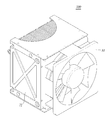
도 5은 본 발명의 실시 예에 따른 연료전지 스택의 체결이 완료된 조립체의 일례를 개략적으로 나타낸 것이다.1 schematically shows an example of a
2 schematically shows an example of an
3 is a side view of the
4 schematically shows an example of the
5 is a schematic view showing an example of an assembled assembly of a fuel cell stack according to an embodiment of the present invention.
상기 목적을 달성하기 위하여, 본 발명의 일 실시 예는In order to achieve the above object,
고분자 전해질막; 상기 고분자 전해질막의 일면에 형성된 애노드 전극; 및 상기 고분자 전해질막의 타면에 형성된 캐소드 전극;을 포함하는 막 전극 접합체(MEA;membrane electrode assembly)(11); 상기 막 전극 접합체의 일면에 접하는 제1 가스 확산층(21); 상기 막 전극 접합체의 타면에 접하는 제2 가스 확산층(22); 상기 제1 가스 확산층 일면에 접하고, 일부가 요철 형태로 절곡되어 산소연료 주입과 공냉을 동시에 수행하는 복합 유로를 포함하는 캐소드 분리판(41); 상기 제2 가스 확산층 일면에 접하고 수소 유로가 형성된 애노드 분리판(42); 상기 캐소드 분리판의 복합 유로 상단 및 하단에 각각 위치하는 제1 가스켓(31); 및 제2 가스켓(32); 상기 애노드 분리판과 상기 제2 가스 확산층 사이에 위치하는 제3 가스켓(33);을 포함하는 연료전지(101)를 제공한다.Polymer Electrolyte Membrane; An anode electrode formed on one surface of the polymer electrolyte membrane; A membrane electrode assembly (MEA) 11 including a cathode electrode formed on the other surface of the polymer electrolyte membrane; A first gas diffusion layer (21) in contact with one surface of the membrane electrode assembly; A second gas diffusion layer (22) in contact with the other surface of the membrane electrode assembly; A
이때, 도 1 내지 도 3에 본 발명의 실시 예에 따른 연료전지(101)의 일례를 모식도를 통해 개략적으로 나타내었으며, 이하, 도 1 내지 도 3을 참조하여, 본 발명의 실시 예에 따른 연료전지를 상세히 설명한다.1 to 3 schematically show an example of a
본 발명의 일 실시 예에 따른 연료전지는, 수소 이온(H+)이 이동 가능한 고분자 전해질막(미도시); 상기 고분자 전해질막의 일면에 형성되고, 촉매를 포함하는 애노드 전극(미도시); 및 상기 고분자 전해질막의 타면에 형성된 캐소드 전극(미도시);을 포함하는 막 전극 접합체(MEA;membrane electrode assembly)(11);를 구비하고, 상기 막 전극 접합체의 일면에 접하는 제1 가스 확산층(21); 상기 막 전극 접합체의 타면에 접하는 제2 가스 확산층(22); 상기 제1 가스 확산층 일면에 접하고, 일부가 요철 형태로 절곡되어 산소연료 주입과 공냉을 동시에 수행하는 복합 유로를 포함하는 캐소드 분리판(41); 상기 제2 가스 확산층 일면에 접하고 1개 이상의 S자형 수소 유로가 형성된 애노드 분리판(42); 상기 캐소드 분리판의 복합 유로 상단 및 하단에 각각 위치하는 제1 가스켓(31); 및 제2 가스켓(32); 상기 애노드 분리판과 상기 제2 가스 확산층 사이에 위치하는 제3 가스켓(33);을 포함하는 연료전지(101)로 구성될 수 있다.A fuel cell according to an embodiment of the present invention includes a polymer electrolyte membrane (not shown) to which hydrogen ions (H + ) can move; An anode electrode (not shown) formed on one side of the polymer electrolyte membrane and including a catalyst; And a membrane electrode assembly (MEA) 11 including a cathode electrode (not shown) formed on the other surface of the polymer electrolyte membrane, and a first gas diffusion layer 21 ); A second gas diffusion layer (22) in contact with the other surface of the membrane electrode assembly; A
상기 연료전지(101)의 애노드 전극(미도시)에서는 수소의 산화반응이 진행되어 수소 이온(H+)과 전자(e-)가 발생하며, 이때 생성된 수소이온은 고분자 전해질막(미도시)을 통해 캐소드 전극으로 이동하고, 전자는 애노드 전극으로부터 제2 가스 확산층, 애노드 분리판(42), 캐소드 분리판(41) 및 제1 가스확산층(21)을 거쳐 캐소드 전극으로 이동하게 된다. 이와 동시에 캐소드 전극(미도시)에서는 애노드 전극으로부터 수소이온과 전자를 받아 산소의 환원반응이 진행되면서 물을 생성하고, 전자의 흐름 및 고분자 전해질막을 통하는 수소 이온의 흐름에 의하여 전기에너지가 생성된다.In the anode electrode (not shown) of the
상기 고분자 전해질막(미도시)은 불소계 고분자, 벤즈이미다졸계 고분자, 케톤계 고분자, 에스테르계 고분자, 아미드계 고분자 및 이미드계 고분자 등을 사용할 수 있으며, 수소이온을 전도할 수 있는 물질이라면 이에 제한하는 것은 아니다.The polymer electrolyte membrane (not shown) may include a fluorine-based polymer, a benzimidazole-based polymer, a ketone-based polymer, an ester-based polymer, an amide-based polymer, and an imide-based polymer. It does not.
상기 애노드 전극(미도시) 및 캐소드 전극(미도시)은 백금, 금, 루테늄, 오스뮴, 세륨, 주석, 텅스텐, 티타늄, 몰리브덴, 철, 바나듐, 망간, 코발트, 크롬, 니켈, 팔라듐, 로듐 및 이리듐 등을 사용할 수 있으나, 이에 제한하는 것은 아니다.The anode electrode (not shown) and the cathode electrode (not shown) may be formed of platinum, gold, ruthenium, osmium, cerium, tin, tungsten, titanium, molybdenum, iron, vanadium, manganese, cobalt, chromium, nickel, palladium, And the like may be used, but the present invention is not limited thereto.
상기 제1 가스 확산층(21)은 상기 막 전극 접합체(11)와 캐소드 분리판(41) 사이에 위치하며, 산소 기체 및 물의 확산과 전자의 이동을 용이하게 한다.The first
상기 제2 가스 확산층(22)은 상기 막 전극 접합체(11)와 애노드 분리판(42) 사이에 위치하며, 수소 기체의 확산 및 전자의 이동을 용이하게 한다.The second
상기 제1 가스확산층(21) 및 제2 가스확산층(22)은 시트 타입의 카본 합성물(composite), 카본 페이퍼(carbon paper), 카본 클로스(carbon cloth) 등을 사용할 수 있으나, 기체 및 물의 확산과 전자의 이동이 효과적으로 이루어질 수 있는 물질이라면 이에 제한하는 것은 아니다.The first
상기 제1 가스켓(31) 및 제2 가스켓(32)은 상기 캐소드 분리판(41)의 절곡된 요철 형태의 복합 유로 높이와 동일한 두께를 갖는 것이 바람직하다.It is preferable that the
이때, 연료전지를 구성하는 구성요소들이 적층되며 체결될 시 캐소드 분리판의 응력 집중을 최소화하고, 수소연료가 상기 애노드 분리판(42)으로 주입되는 유로를 확보할 수 있으며, 애노드 판으로 주입되는 수소와 공기(산소)의 혼입을 방지할 수 있다.At this time, when components constituting the fuel cell are laminated and fastened, stress concentration of the cathode separation plate is minimized, a flow path for injecting hydrogen fuel into the
구체적으로, 상기 제1 가스켓은 상기 캐소드 분리판의 복합 유로 상단에 위치할 수 있고, 상기 제2 가스켓은 상기 캐소드 분리판의 복합 유로 하단에 위치하여 체결될 수 있다.Specifically, the first gasket may be located at the upper end of the composite flow path of the cathode separation plate, and the second gasket may be positioned at the lower end of the composite flow passage of the cathode separation plate.
상기 캐소드 분리판(41)은 도 3과 같이 요철 형태로 절곡되어 산소(공기)연료 주입과 공냉을 동시에 수행하는 복합 유로를 형성할 수 있다.The
구체적으로, 요철 형태로 절곡된 구조를 갖는 캐소드 분리판이 제1 가스 확산층과 접할 시 산소(공기)연료 유로가 형성되며, 상기 요철 형태로 절곡된 구조를 갖는 캐소드 분리판이 다른 애노드 분리판(42)과 접할 시 공냉 유로가 형성된다.Specifically, an oxygen (air) fuel flow path is formed when the cathode separator having a structure bent in a concavo-convex shape contacts with the first gas diffusion layer, and the cathode separator having a structure bent in the concavo- The air cooling passage is formed.
상기와 같이 형성된 산소연료 유로와 공냉 유로로 공기를 주입하여, 산소연료 공급 및 공기의 대류로 인한 연료전지의 냉각을 용이하게 할 수 있다.Air can be injected into the oxygen fuel flow path and the air cooling flow path formed as described above to facilitate cooling of the fuel cell due to oxygen fuel supply and air convection.
이때, 캐소드 분리판의 절곡된 요철 형태는 복합 유로를 형성하고, 연료전지 적층 체결시 발생하는 국부적인 응력을 최소화하면서 기밀성을 유지할 수 있는 형태라면 이에 제한하는 것은 아니다.At this time, the bent shape of the cathode separator plate is not limited to the one that forms the multiple flow path and can maintain the airtightness while minimizing the local stress generated in the fuel cell stacking.
상기와 같이 복합 유로가 형성된 연료전지는 산소연료 주입과 공냉이 동시에 수행됨으로 인해, 종래의 연료전지가 갖는 냉각을 위한 주변장치(냉각 유로, 냉각수 등)를 최소화할 수 있는 장점이 있으며, 이로 인해 경량화가 가능하고 무인 항공기 등의 운송수단 발전용으로 용이하게 사용할 수 있다.Since the oxygen fuel injection and the air cooling are simultaneously performed in the fuel cell having the complex flow path as described above, there is an advantage in that the peripheral devices (cooling channels, cooling water, etc.) for cooling of the conventional fuel cell can be minimized, It can be lightweight and can be easily used for power generation of vehicles such as unmanned aerial vehicles.
상기 애노드 분리판(42)은 도 2에 도시된 바와 같이 수소 유로를 형성하는 말단이 만곡된(curved) 돌출부를 갖는 것이 바람직하다.It is preferable that the
구체적으로, 상기 애노드 분리판에 적어도 2개 이상의 S자(serpentine) 형상을 갖는 말단이 만곡된 돌출부를 형성함으로써, 돌출부와 타 돌출부 사이인 요부에 수소가 이송될 수 있는 수소 유로 적어도 1개 이상 갖출 수 있다.Specifically, at least two or more serpentine protrusions are formed on the anode separator to provide at least one hydrogen flow path through which the hydrogen can be transferred to the recesses between the protrusions and the other protrusions. .
또한, 상기 애노드 분리판의 만곡된 돌출부로 인해, 연료전지를 구성하는 구성요소들이 적층되며 체결될 시, 애노드 분리판의 만곡된 돌출부와 접하는 제2 가스확산층의 변형을 최소화할 수 있다.Further, due to the curved protrusion of the anode separator, deformation of the second gas diffusion layer contacting with the curved protrusion of the anode separator plate can be minimized when the constituent elements constituting the fuel cell are laminated and fastened.
종래 캐소드 분리판 및 애노드 분리판은 탄소계 재료를 사용하여 기계가공을 통해 유로를 제작하였고, 상기 탄소계 분리판은 막 전극 접합체(MEA) 양쪽면에 위치되는 각 가스 확산층의 바깥면 쪽에 배치되며 냉각유로와 연료 유로를 갖는다.Conventionally, the cathode separator and the anode separator were manufactured by machining using a carbon-based material, and the carbon separator was disposed on the outer surface side of each gas diffusion layer positioned on both sides of the membrane electrode assembly (MEA) And has a cooling channel and a fuel channel.
그러나 이러한 탄소계 분리판은 제작비용이 많이 들뿐 아니라 열 및 전기 전달효율이 낮고 강도 문제로 인해 분리판 자체를 박판화 시키는 것이 어려우며, 제작 후에 내 충격 특성이 좋지 않은 단점이 있었다.However, such a carbon-based separator is not only expensive to manufacture but also has a low heat and electric transfer efficiency, and it is difficult to thin the separator itself due to the strength problem, and the shock resistance characteristic is poor after fabrication.
본 발명의 일 실시 예에서는 분리판인 캐소드 분리판(41) 및 애노드 분리판(42)의 재료를 강도가 우수하며 동시에 박판화가 용이한 금속 분리판을 이용한다. 상기 금속 분리판은 기계가공을 통해 유로를 제작하는 탄소계 분리판에 비해 제작시간 및 비용을 현저히 낮출 수 있는 장점이 있다.In an embodiment of the present invention, the material of the
이때, 상기 캐소드 분리판 및 애노드 분리판은 스테인리스강, 알루미늄, 구리, 니켈, 티타늄 및 이들의 합금을 사용할 수 있으나, 이에 제한하는 것은 아니다.The cathode separation plate and the anode separation plate may be made of stainless steel, aluminum, copper, nickel, titanium, or an alloy thereof. However, the present invention is not limited thereto.
상기 제3 가스켓의 두께는 상기 애노드 분리판(42)의 돌출부 높이와 동일한 것이 바람직하다.The thickness of the third gasket is preferably the same as the height of the projecting portion of the
이때, 연료전지(101)를 구성하는 구성요소들이 적층되며 체결될 시 애노드 분리판 돌출부의 응력 집중을 감소시키고, 수소연료가 상기 애노드 분리판으로 주입되는 유로의 기밀성을 확보할 수 있다.At this time, when the constituent elements of the
나아가, 본 발명의 일 실시 예는Further, an embodiment of the present invention
상기의 연료전지(101)를 적어도 2개 이상 포함하고, 상기 연료전지를 적층 시 적층 단부에 집전판(61, 62), 엔드 플레이트(71, 72, 73, 74) 및 적층판 일측면에 공기대류 팬(fan)(81)을 더 포함하는 것을 특징으로 하는 연료전지 스택(100)을 제공한다.(61, 62), end plates (71, 72, 73, 74) at one end of the stacked layer when the fuel cell is stacked, and air convection And a fan (81) connected to the fuel cell stack (100).
이때, 도 4 및 도 5에 본 발명의 일 실시 예에 따른 연료전지 스택(100)의 일례를 모식도를 통해 개략적으로 나타내었으며, 이하, 도 4 및 도 5를 참조하여, 본 발명의 일 실시 예에 따른 연료전지 스택에 대하여 상세히 설명한다.4 and 5 schematically show an example of the
본 발명의 일 실시 예에 따른 연료전지 스택(100)은, 상기의 연료전지(101)를 적어도 2개 이상 포함하고, 상기 연료전지를 적층 시 적층 단부에 제1 집전판(61) 및 제2 집전판(62)을 더 포함하며, 스택을 마감하는 제1 엔드 플레이트(71), 제2 엔드 플레이트(72), 제3 엔드 플레이트(73), 제4 엔드 플레이트(74) 및 적층판 일측면에 공기대류 팬(fan)(81)을 더 포함한다.The
상기 제1 집전판(61), 적어도 2개 이상의 연료전지(101) 및 제2 집전판(62)을 통해 전자의 흐름이 발생할 수 있다. 구체적으로, 상기 연료전지 내 막 전극 접합체에서 수소연료가 수소 이온 및 전자로 분리되고, 이때 발생한 전자는 애노드 분리판(42)을 거쳐 최종적으로 제2 집전판에 도달하며 전류가 흐르게 될 수 있다.Electrons may flow through the first
상기 제1 엔드 플레이트(71)는 상기 제1 집전판(61)의 일면에 위치하여, 적층을 마감하고, 지지하는 역할을 한다.The
또한, 상기 제2 엔드 플레이트(72)는 상기 제2 집전판(62)의 일면에 위치하여, 적층을 마감하고, 지지하는 역할을 한다.The
나아가, 상기 제3 엔드 플레이트(73)는 적어도 2개 이상의 연료전지가 적층된 제1 가스켓(31)들의 상부에 위치하며, 연료전지들의 상단을 마감하는 역할을 한다.Furthermore, the
더욱 나아가, 상기 제4 엔드 플레이트(74)는 적어도 2개 이상의 연료전지가 적층된 제2 가스켓(32)들의 하부에 위치하며, 연료전지들의 하단을 마감하는 역할을 한다.Furthermore, the
상기 공기대류 팬(81)은 적어도 2개 이상이 적층된 연료전지(101)의 캐소드 분리판(41)에 형성된 복합 유로 내부로 산소(공기)연료를 주입하고, 공냉을 동시에 수행하도록 할 수 있다.The
이때, 상기 캐소드 분리판의 복합 유로에 발생하는 공기 대류로 인해 연료전지 반응 생성물인 물을 연료전지 외부로 배출시킬 수 있다.At this time, water, which is a fuel cell reaction product, can be discharged to the outside of the fuel cell due to air convection generated in the composite flow path of the cathode separator.
도 5에 본 발명의 일 실시 예에 따른 연료전지 스택(100)이 체결된 조립체의 일례를 도시하였다.FIG. 5 shows an example of an assembly in which the
상기 연료전지 스택의 제1 집전체(61) 및 제2 집전체(62)와 외부 회로를 전기적으로 연결하고, 연료전지 스택의 상단과 하단에 형성된 수소연료 주입부에 수소를 주입하며, 공기대류 팬(81)을 구동하여 산소(공기)연료 및 공냉을 수행함으로써 연료전지 스택이 작동될 수 있다.The first
따라서, 본 발명의 일 실시 예에 따른 개방형 유로가 구비된 연료전지 스택은 산소연료 주입과 공냉을 동시에 수행 가능하고, 이에 연료전지에서 발생하는 열과 수분을 효율적으로 방출할 수 있으며, 간소화된 구조로 인해 경량화, 제조 비용 절감이 가능하다.Therefore, the fuel cell stack having the open channel according to the embodiment of the present invention can simultaneously perform oxygen fuel injection and air cooling, and can efficiently discharge heat and moisture generated in the fuel cell, and a simplified structure Thus making it possible to reduce the weight and manufacturing cost.
본 발명은 상술한 실시 형태 및 첨부된 도면에 의해 한정되는 것이 아니며 첨부된 청구범위에 의해 한정하고자 한다. 따라서, 청구범위에 기재된 본 발명의 기술적 사상을 벗어나지 않는 범위 내에서 당 기술분야의 통상의 지식을 가진 자에 의해 다양한 형태의 치환, 변형 및 변경이 가능할 것이며, 이 또한 본 발명의 범위에 속한다고 할 것이다.The present invention is not limited to the above-described embodiment and the accompanying drawings, but is intended to be limited by the appended claims. It will be apparent to those skilled in the art that various changes in form and details may be made therein without departing from the spirit and scope of the invention as defined by the appended claims. something to do.
11 : 막 전극 접합체(MEA)
21 : 제1 가스 확산층
22 : 제2 가스 확산층
31 : 제1 가스켓
32 : 제2 가스켓
33 : 제3 가스켓
41 : 캐소드 분리판
42 : 애노드 분리판
61 : 제1 집전판
62 : 제2 집전판
71 : 제1 엔드 플레이트
72 : 제2 엔드 플레이트
73 : 제3 엔드 플레이트
74 : 제4 엔드 플레이트
81 : 공기대류 팬
100 : 연료전지 스택
101 : 연료전지11: membrane electrode assembly (MEA) 21: first gas diffusion layer
22: second gas diffusion layer 31: first gasket
32: second gasket 33: third gasket
41: cathode separation plate 42: anode separation plate
61: 1st Edition, Full Version 62: 2nd Edition, Full Version
71: first end plate 72: second end plate
73: third end plate 74: fourth end plate
81: air convection fan 100: fuel cell stack
101: Fuel cell
Claims (8)
상기 막 전극 접합체의 일면에 접하는 제1 가스 확산층;
상기 막 전극 접합체의 타면에 접하는 제2 가스 확산층;
상기 제1 가스 확산층 일면에 접하고, 일부가 요철 형태로 절곡되어 산소연료 주입과 공냉을 동시에 수행하는 복합 유로를 포함하는 캐소드 분리판;
상기 제2 가스 확산층 일면에 접하고 수소 유로가 형성된 애노드 분리판;
상기 캐소드 분리판의 복합 유로 상단 및 하단에 각각 위치하는 제1 가스켓; 및 제2 가스켓;
상기 애노드 분리판과 상기 제2 가스 확산층 사이에 위치하는 제3 가스켓;을 포함하는 연료전지.
Polymer Electrolyte Membrane; An anode electrode formed on one surface of the polymer electrolyte membrane; And a cathode electrode formed on the other surface of the polymer electrolyte membrane, the membrane electrode assembly comprising: a membrane electrode assembly (MEA)
A first gas diffusion layer in contact with one surface of the membrane electrode assembly;
A second gas diffusion layer contacting the other surface of the membrane electrode assembly;
A cathode separation plate including a composite flow path which is in contact with one surface of the first gas diffusion layer and is partially bent in a concavo-convex form to simultaneously perform oxygen fuel injection and air cooling;
An anode separator which is in contact with one surface of the second gas diffusion layer and has a hydrogen flow path;
A first gasket positioned at an upper end and a lower end of the multiple flow path of the cathode separation plate, respectively; And a second gasket;
And a third gasket positioned between the anode separation plate and the second gas diffusion layer.
상기 제1 가스켓 및 제2 가스켓은 상기 캐소드 분리판의 복합 유로 높이와 동일한 두께를 갖는 것을 특징으로 하는 연료전지.
The method according to claim 1,
Wherein the first gasket and the second gasket have a thickness equal to the height of the multiple passage of the cathode separator.
상기 애노드 분리판은 수소 유로를 형성하는 말단이 만곡된(curved) 돌출부를 갖는 것을 특징으로 하는 연료전지.
The method according to claim 1,
Wherein the anode separator plate has a curved protrusion which forms a hydrogen flow path.
상기 제3 가스켓의 두께는 제3항의 애노드 분리판의 돌출부 높이와 동일한 것을 특징으로 하는 연료전지.
The method according to claim 1,
And the thickness of the third gasket is the same as the height of the protrusion of the anode separator of claim 3.
상기 애노드 전극 및 캐소드 전극은 백금, 금, 루테늄, 오스뮴, 세륨, 주석, 텅스텐, 티타늄, 몰리브덴, 철, 바나듐, 망간, 코발트, 크롬, 니켈, 팔라듐, 로듐 및 이리듐으로 이루어지는 군으로부터 선택된 1종 이상인 것을 특징으로 하는 연료전지.
The method according to claim 1,
The anode electrode and the cathode electrode may be at least one selected from the group consisting of platinum, gold, ruthenium, osmium, cerium, tin, tungsten, titanium, molybdenum, iron, vanadium, manganese, cobalt, chromium, nickel, palladium, rhodium and iridium And a fuel cell.
상기 고분자 전해질막은 불소계 고분자, 벤즈이미다졸계 고분자, 케톤계 고분자, 에스테르계 고분자, 아미드계 고분자 및 이미드계 고분자로 이루어지는 군으로부터 선택되는 1종 이상인 것을 특징으로 하는 연료전지.
The method according to claim 1,
Wherein the polymer electrolyte membrane is at least one selected from the group consisting of a fluorine-based polymer, a benzimidazole-based polymer, a ketone-based polymer, an ester-based polymer, an amide-based polymer, and an imide-based polymer.
상기 제1 가스 확산층 및 제2 가스 확산층은 시트(sheet) 형태의 카본 합성물(composite), 카본 페이퍼(carbon paper), 카본 클로스(carbon cloth)로 이루어지는 군으로부터 선택되는 1종 이상인 것을 특징으로 하는 연료전지.
The method according to claim 1,
Wherein the first gas diffusion layer and the second gas diffusion layer are at least one selected from the group consisting of sheet-shaped carbon composite, carbon paper, and carbon cloth. battery.
A fuel cell stack comprising at least two fuel cells according to claim 1, and further comprising a current collecting plate, an end plate, and an air convection fan at one side of the laminated plate at the lamination end when the fuel cell is stacked.
Priority Applications (1)
| Application Number | Priority Date | Filing Date | Title |
|---|---|---|---|
| KR1020150187350A KR20170077897A (en) | 2015-12-28 | 2015-12-28 | Fuel cell stack having open flow passage |
Applications Claiming Priority (1)
| Application Number | Priority Date | Filing Date | Title |
|---|---|---|---|
| KR1020150187350A KR20170077897A (en) | 2015-12-28 | 2015-12-28 | Fuel cell stack having open flow passage |
Publications (1)
| Publication Number | Publication Date |
|---|---|
| KR20170077897A true KR20170077897A (en) | 2017-07-07 |
Family
ID=59353434
Family Applications (1)
| Application Number | Title | Priority Date | Filing Date |
|---|---|---|---|
| KR1020150187350A Ceased KR20170077897A (en) | 2015-12-28 | 2015-12-28 | Fuel cell stack having open flow passage |
Country Status (1)
| Country | Link |
|---|---|
| KR (1) | KR20170077897A (en) |
Cited By (4)
| Publication number | Priority date | Publication date | Assignee | Title |
|---|---|---|---|---|
| KR20220069447A (en) * | 2020-11-20 | 2022-05-27 | 인하대학교 산학협력단 | Apparatus for measuring performance of unit cell in fuel cell |
| CN119518012A (en) * | 2024-11-28 | 2025-02-25 | 广东云韬氢能科技有限公司 | A wind-driven air-supply type air-cooled battery stack and bipolar plate |
| US12374704B2 (en) | 2022-02-17 | 2025-07-29 | Terralix Co., Ltd. | Air-cooling type fuel cell capable of air recirculation |
| US12542285B2 (en) | 2021-11-19 | 2026-02-03 | Terralix Co., Ltd. | Air supply apparatus for fuel cell |
-
2015
- 2015-12-28 KR KR1020150187350A patent/KR20170077897A/en not_active Ceased
Cited By (4)
| Publication number | Priority date | Publication date | Assignee | Title |
|---|---|---|---|---|
| KR20220069447A (en) * | 2020-11-20 | 2022-05-27 | 인하대학교 산학협력단 | Apparatus for measuring performance of unit cell in fuel cell |
| US12542285B2 (en) | 2021-11-19 | 2026-02-03 | Terralix Co., Ltd. | Air supply apparatus for fuel cell |
| US12374704B2 (en) | 2022-02-17 | 2025-07-29 | Terralix Co., Ltd. | Air-cooling type fuel cell capable of air recirculation |
| CN119518012A (en) * | 2024-11-28 | 2025-02-25 | 广东云韬氢能科技有限公司 | A wind-driven air-supply type air-cooled battery stack and bipolar plate |
Similar Documents
| Publication | Publication Date | Title |
|---|---|---|
| JP6368807B2 (en) | Manufacturing method of fuel cell stack and manufacturing method of metal separator for fuel cell | |
| US9269969B2 (en) | Fuel cell stack | |
| US20140017590A1 (en) | Electrolyte membrane-electrode assembly for fuel cells, and method for producing same | |
| CN110224154B (en) | Frame-equipped membrane electrode assembly, method for producing same, and fuel cell | |
| US8431284B2 (en) | Low electrical resistance bipolar plate-diffusion media assembly | |
| JP6092060B2 (en) | Electrolyte membrane / electrode structure with resin frame for fuel cells | |
| US9490497B2 (en) | Solid polymer electrolyte type fuel cell, and electrolyte membrane-electrode-frame assembly | |
| US11302935B2 (en) | Fuel cell stack, dummy cell for fuel cell stack, and method of producing dummy cell | |
| US7531265B2 (en) | Fuel cell | |
| JP5011627B2 (en) | Fuel cell | |
| US10297841B2 (en) | Fuel cell and production apparatus for the fuel cell | |
| JP2018129174A (en) | Metal separator for fuel cell, method for producing the same, and power generation cell | |
| US10559835B2 (en) | Resin-framed membrane-electrode assembly for fuel cell | |
| JP5454301B2 (en) | Fuel cell stack | |
| JP2005149748A (en) | Separator | |
| JP2017168370A (en) | Step MEA with resin frame for fuel cell and manufacturing method thereof | |
| US10847826B2 (en) | Polymer electrolyte fuel cells and production method thereof | |
| EP2244324B1 (en) | Cambered Flow-field Plate | |
| US9673475B2 (en) | Fuel cell stack | |
| JP2012195128A (en) | Gasket for polymer electrolyte fuel cell and polymer electrolyte fuel cell | |
| JP5664457B2 (en) | FUEL CELL SEPARATOR PLATE, FUEL CELL SEPARATOR, FUEL CELL, AND METHOD FOR PRODUCING FUEL CELL SEPARATOR PLATE | |
| JP6681537B2 (en) | Joined body, fuel cell using the joined body, and method for disassembling the same | |
| CN106104878A (en) | Fuel cell | |
| JP7649140B2 (en) | Fuel cell separator and fuel cell stack | |
| JP2009238572A (en) | Separator used for fuel cell, and method of manufacturing separator |
Legal Events
| Date | Code | Title | Description |
|---|---|---|---|
| PA0109 | Patent application |
Patent event code: PA01091R01D Comment text: Patent Application Patent event date: 20151228 |
|
| A201 | Request for examination | ||
| PA0201 | Request for examination |
Patent event code: PA02012R01D Patent event date: 20160928 Comment text: Request for Examination of Application Patent event code: PA02011R01I Patent event date: 20151228 Comment text: Patent Application |
|
| PG1501 | Laying open of application | ||
| E902 | Notification of reason for refusal | ||
| PE0902 | Notice of grounds for rejection |
Comment text: Notification of reason for refusal Patent event date: 20171116 Patent event code: PE09021S01D |
|
| E601 | Decision to refuse application | ||
| PE0601 | Decision on rejection of patent |
Patent event date: 20180424 Comment text: Decision to Refuse Application Patent event code: PE06012S01D Patent event date: 20171116 Comment text: Notification of reason for refusal Patent event code: PE06011S01I |