KR20170092904A - 조향모터제어장치 및 조향모터제어방법 - Google Patents
조향모터제어장치 및 조향모터제어방법 Download PDFInfo
- Publication number
- KR20170092904A KR20170092904A KR1020160014167A KR20160014167A KR20170092904A KR 20170092904 A KR20170092904 A KR 20170092904A KR 1020160014167 A KR1020160014167 A KR 1020160014167A KR 20160014167 A KR20160014167 A KR 20160014167A KR 20170092904 A KR20170092904 A KR 20170092904A
- Authority
- KR
- South Korea
- Prior art keywords
- sensor
- output
- measurement area
- steering motor
- value
- Prior art date
- Legal status (The legal status is an assumption and is not a legal conclusion. Google has not performed a legal analysis and makes no representation as to the accuracy of the status listed.)
- Granted
Links
Images

Classifications
-
- B—PERFORMING OPERATIONS; TRANSPORTING
- B62—LAND VEHICLES FOR TRAVELLING OTHERWISE THAN ON RAILS
- B62D—MOTOR VEHICLES; TRAILERS
- B62D5/00—Power-assisted or power-driven steering
- B62D5/04—Power-assisted or power-driven steering electrical, e.g. using an electric servo-motor connected to, or forming part of, the steering gear
- B62D5/0457—Power-assisted or power-driven steering electrical, e.g. using an electric servo-motor connected to, or forming part of, the steering gear characterised by control features of the drive means as such
- B62D5/0481—Power-assisted or power-driven steering electrical, e.g. using an electric servo-motor connected to, or forming part of, the steering gear characterised by control features of the drive means as such monitoring the steering system, e.g. failures
- B62D5/049—Power-assisted or power-driven steering electrical, e.g. using an electric servo-motor connected to, or forming part of, the steering gear characterised by control features of the drive means as such monitoring the steering system, e.g. failures detecting sensor failures
-
- B—PERFORMING OPERATIONS; TRANSPORTING
- B62—LAND VEHICLES FOR TRAVELLING OTHERWISE THAN ON RAILS
- B62D—MOTOR VEHICLES; TRAILERS
- B62D5/00—Power-assisted or power-driven steering
- B62D5/04—Power-assisted or power-driven steering electrical, e.g. using an electric servo-motor connected to, or forming part of, the steering gear
- B62D5/0457—Power-assisted or power-driven steering electrical, e.g. using an electric servo-motor connected to, or forming part of, the steering gear characterised by control features of the drive means as such
- B62D5/046—Controlling the motor
-
- B—PERFORMING OPERATIONS; TRANSPORTING
- B62—LAND VEHICLES FOR TRAVELLING OTHERWISE THAN ON RAILS
- B62D—MOTOR VEHICLES; TRAILERS
- B62D5/00—Power-assisted or power-driven steering
- B62D5/04—Power-assisted or power-driven steering electrical, e.g. using an electric servo-motor connected to, or forming part of, the steering gear
- B62D5/0457—Power-assisted or power-driven steering electrical, e.g. using an electric servo-motor connected to, or forming part of, the steering gear characterised by control features of the drive means as such
- B62D5/0481—Power-assisted or power-driven steering electrical, e.g. using an electric servo-motor connected to, or forming part of, the steering gear characterised by control features of the drive means as such monitoring the steering system, e.g. failures
- B62D5/0484—Power-assisted or power-driven steering electrical, e.g. using an electric servo-motor connected to, or forming part of, the steering gear characterised by control features of the drive means as such monitoring the steering system, e.g. failures for reaction to failures, e.g. limp home
-
- G—PHYSICS
- G01—MEASURING; TESTING
- G01R—MEASURING ELECTRIC VARIABLES; MEASURING MAGNETIC VARIABLES
- G01R19/00—Arrangements for measuring currents or voltages or for indicating presence or sign thereof
- G01R19/165—Indicating that current or voltage is either above or below a predetermined value or within or outside a predetermined range of values
- G01R19/16566—Circuits and arrangements for comparing voltage or current with one or several thresholds and for indicating the result not covered by subgroups G01R19/16504, G01R19/16528, G01R19/16533
-
- G—PHYSICS
- G01—MEASURING; TESTING
- G01R—MEASURING ELECTRIC VARIABLES; MEASURING MAGNETIC VARIABLES
- G01R31/00—Arrangements for testing electric properties; Arrangements for locating electric faults; Arrangements for electrical testing characterised by what is being tested not provided for elsewhere
- G01R31/34—Testing dynamo-electric machines
- G01R31/343—Testing dynamo-electric machines in operation
-
- G—PHYSICS
- G08—SIGNALLING
- G08B—SIGNALLING SYSTEMS, e.g. PERSONAL CALLING SYSTEMS; ORDER TELEGRAPHS; ALARM SYSTEMS
- G08B21/00—Alarms responsive to a single specified undesired or abnormal condition and not otherwise provided for
- G08B21/18—Status alarms
- G08B21/182—Level alarms, e.g. alarms responsive to variables exceeding a threshold
-
- G—PHYSICS
- G08—SIGNALLING
- G08B—SIGNALLING SYSTEMS, e.g. PERSONAL CALLING SYSTEMS; ORDER TELEGRAPHS; ALARM SYSTEMS
- G08B21/00—Alarms responsive to a single specified undesired or abnormal condition and not otherwise provided for
- G08B21/18—Status alarms
- G08B21/185—Electrical failure alarms
-
- H—ELECTRICITY
- H02—GENERATION; CONVERSION OR DISTRIBUTION OF ELECTRIC POWER
- H02P—CONTROL OR REGULATION OF ELECTRIC MOTORS, ELECTRIC GENERATORS OR DYNAMO-ELECTRIC CONVERTERS; CONTROLLING TRANSFORMERS, REACTORS OR CHOKE COILS
- H02P29/00—Arrangements for regulating or controlling electric motors, appropriate for both AC and DC motors
-
- H—ELECTRICITY
- H03—ELECTRONIC CIRCUITRY
- H03F—AMPLIFIERS
- H03F3/00—Amplifiers with only discharge tubes or only semiconductor devices as amplifying elements
- H03F3/20—Power amplifiers, e.g. Class B amplifiers, Class C amplifiers
- H03F3/21—Power amplifiers, e.g. Class B amplifiers, Class C amplifiers with semiconductor devices only
- H03F3/217—Class D power amplifiers; Switching amplifiers
Landscapes
- Engineering & Computer Science (AREA)
- Physics & Mathematics (AREA)
- General Physics & Mathematics (AREA)
- Chemical & Material Sciences (AREA)
- Combustion & Propulsion (AREA)
- Transportation (AREA)
- Mechanical Engineering (AREA)
- Power Engineering (AREA)
- Business, Economics & Management (AREA)
- Emergency Management (AREA)
- Power Steering Mechanism (AREA)
- Steering Control In Accordance With Driving Conditions (AREA)
Abstract
Description
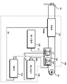
도 2는 본 발명의 일 실시 예에 따른 센서들이 션트저항 및 증폭기로 구성되는 경우에 따른 구성과 동작을 설명하기 위한 상세한 예를 도시한 도면이다.
도 3은 본 발명의 일 실시 예에 따른 조향모터제어장치의 동작을 설명하기 위한 일 예를 도시한 도면이다.
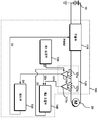
도 4는 본 발명의 다른 일 실시 예에 따른 조향모터제어장치의 구성과 동작을 설명하기 위한 일 예를 도시한 도면이다.
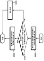
도 5는 본 발명의 다른 일 실시 예에 따른 조향모터제어장치의 동작을 설명하기 위한 일 예를 도시한 도면이다.
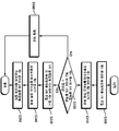
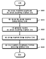
도 6은 본 발명의 일 실시 예에 따른 조향모터제어방법의 흐름도를 도시한 도면이다.
Claims (8)
- 입력단에 연결된 전원을 제어단을 통해 입력받은 제어신호에 기초하여 출력단에 연결된 조향모터에 전류를 출력하는 모듈부;
상기 전류를 측정할 수 있는 복수의 센서들;
상기 복수의 센서들 중 하나인 제1 센서의 측정영역과 제2 센서의 측정영역이 동일하도록 상기 제1 센서의 측정영역을 1차 조절하는 제1 조절부;
측정영역이 1차 조절된 제1 센서와 측정영역이 고정된 상기 제2 센서 각각이 출력한 1차 출력값의 차이가 미리 설정된 정상값 이내이면, 상기 1차 출력값에 기초하여 상기 제1 센서의 측정영역을 2차 조절하는 제2 조절부; 및
측정영역이 2차 조절된 제1 센서가 출력한 2차 출력값에 기초하여 상기 제어신호를 출력하는 제어부를 포함하는 조향모터제어장치. - 제 1항에 있어서,
상기 제1 센서를 포함하는 하나 이상의 센서들은, 션트(Shunt)저항 및 증폭기를 포함하며,
상기 제1 조절부 및 상기 제2 조절부는,
상기 제1 센서에 포함되는 증폭기의 게인을 조절하는 것을 특징으로 하는 조향모터제어장치. - 제 2항에 있어서,
상기 증폭기는, 스위치소자를 포함하고,
상기 제1 조절부 및 상기 제2 조절부는,
상기 제1 센서의 증폭기에 포함되는 스위치소자에 입력되는 스위치신호를 가변시킴으로써, 상기 게인을 조절하는 것을 특징으로 하는 조향모터제어장치. - 제 1항에 있어서,
알림을 제공하는 알림부가 더 포함되고,
상기 알림부는,
측정영역이 1차 조절된 제1 센서와 상기 제2 센서 각각이 출력한 1차 출력값의 차이가 상기 정상값을 초과하면 상기 알림을 제공하는 것을 특징으로 하는 조향모터제어장치. - 입력단에 연결된 전원을 제어단을 통해 입력받은 제어신호에 기초하여 출력단에 연결된 조향모터에 전류를 출력하는 모듈부;
상기 전류를 측정하되 측정영역이 각각 다른 복수의 센서들; 및
상기 복수의 센서들 중 하나이되, 제1 센서의 측정영역은 제2 센서의 측정영역에 대해 1이상의 실수 배이며, 상기 제1 센서가 출력한 출력값을 상기 1이상의 실수로 곱셈 연산한 값과 상기 제2 센서가 출력한 출력값의 차이가 미리 설정된 정상값 이내이면, 상기 제2 센서의 출력값에 기초하여 상기 제어신호를 출력하는 제어부를 포함하는 조향모터제어장치. - 제 5항에 있어서,
알림을 제공하는 알림부가 더 포함되고,
상기 알림부는,
상기 제1 센서가 출력한 출력값을 상기 1이상의 실수로 곱셈 연산한 값과 상기 제2 센서가 출력한 출력값의 차이가 상기 정상값을 초과하면 상기 알림을 제공하는 것을 특징으로 하는 조향모터제어장치. - 입력단에 연결된 전원을 제어단을 통해 입력받은 제어신호에 기초하여 출력단에 연결된 조향모터에 전류를 출력하는 조향모터제어방법에 있어서,
복수의 센서들 중 하나인 제1 센서의 측정영역과 제2 센서의 측정영역이 동일하도록 상기 제1 센서의 측정영역을 1차 조절하는 단계;
측정영역이 1차 조절된 제1 센서와 측정영역이 고정된 상기 제2 센서를 이용하여 상기 전류를 측정하는 단계;
상기 측정영역이 1차 조절된 제1 센서와 측정영역이 고정된 상기 제2 센서 각각이 출력한 1차 출력값의 차이가 미리 설정된 정상값 이내이면, 상기 1차 출력값에 기초하여 상기 제1 센서의 측정영역을 2차 조절하는 단계;
측정영역이 2차 조절된 제1 센서를 이용하여 상기 전류를 측정하는 단계; 및
상기 측정영역이 2차 조절된 제1 센서가 출력한 2차 출력값에 기초하여 상기 제어신호를 출력하는 단계를 포함하는 조향모터제어방법. - 제 7항에 있어서,
알림을 제공하는 단계가 더 포함되고,
상기 알림을 제공하는 단계는,
측정영역이 1차 조절된 제1 센서와 상기 제2 센서 각각이 출력한 1차 출력값의 차이가 상기 정상값을 초과하면 상기 알림을 제공하는 것을 특징으로 하는 조향모터제어방법.
Priority Applications (1)
| Application Number | Priority Date | Filing Date | Title |
|---|---|---|---|
| KR1020160014167A KR102436847B1 (ko) | 2016-02-04 | 2016-02-04 | 조향모터제어장치 및 조향모터제어방법 |
Applications Claiming Priority (1)
| Application Number | Priority Date | Filing Date | Title |
|---|---|---|---|
| KR1020160014167A KR102436847B1 (ko) | 2016-02-04 | 2016-02-04 | 조향모터제어장치 및 조향모터제어방법 |
Publications (2)
| Publication Number | Publication Date |
|---|---|
| KR20170092904A true KR20170092904A (ko) | 2017-08-14 |
| KR102436847B1 KR102436847B1 (ko) | 2022-08-26 |
Family
ID=60142013
Family Applications (1)
| Application Number | Title | Priority Date | Filing Date |
|---|---|---|---|
| KR1020160014167A Active KR102436847B1 (ko) | 2016-02-04 | 2016-02-04 | 조향모터제어장치 및 조향모터제어방법 |
Country Status (1)
| Country | Link |
|---|---|
| KR (1) | KR102436847B1 (ko) |
Cited By (2)
| Publication number | Priority date | Publication date | Assignee | Title |
|---|---|---|---|---|
| KR20230055472A (ko) | 2021-10-18 | 2023-04-26 | 정진근 | 콤바인 오거 회전용 모터 |
| KR20230062910A (ko) | 2021-11-01 | 2023-05-09 | 정진근 | 이앙기 조향핸들의 각도 제어용 bldc 모터 |
Citations (7)
| Publication number | Priority date | Publication date | Assignee | Title |
|---|---|---|---|---|
| JPH09126919A (ja) * | 1995-09-29 | 1997-05-16 | Trw Inc | パワー・アシスト・ステアリング・システムのためのトルク・センサの自動ゲイン制御装置 |
| JP2001039323A (ja) * | 1999-07-27 | 2001-02-13 | Nsk Ltd | 電動パワーステアリング装置の制御装置 |
| JP2003312492A (ja) * | 2002-04-22 | 2003-11-06 | Honda Motor Co Ltd | 電動パワーステアリング装置における初期調整方法 |
| JP2004058748A (ja) * | 2002-07-26 | 2004-02-26 | Toyoda Mach Works Ltd | 車両用操舵制御システム |
| KR20100090875A (ko) * | 2009-02-09 | 2010-08-18 | 주식회사 만도 | 션트 저항을 이용한 전류 검출 장치 및 그를 이용한 전자제어장치 |
| JP2013255372A (ja) * | 2012-06-08 | 2013-12-19 | Denso Corp | 電源システム |
| JP2014016256A (ja) * | 2012-07-09 | 2014-01-30 | Toyota Motor Corp | 蓄電システム |
-
2016
- 2016-02-04 KR KR1020160014167A patent/KR102436847B1/ko active Active
Patent Citations (7)
| Publication number | Priority date | Publication date | Assignee | Title |
|---|---|---|---|---|
| JPH09126919A (ja) * | 1995-09-29 | 1997-05-16 | Trw Inc | パワー・アシスト・ステアリング・システムのためのトルク・センサの自動ゲイン制御装置 |
| JP2001039323A (ja) * | 1999-07-27 | 2001-02-13 | Nsk Ltd | 電動パワーステアリング装置の制御装置 |
| JP2003312492A (ja) * | 2002-04-22 | 2003-11-06 | Honda Motor Co Ltd | 電動パワーステアリング装置における初期調整方法 |
| JP2004058748A (ja) * | 2002-07-26 | 2004-02-26 | Toyoda Mach Works Ltd | 車両用操舵制御システム |
| KR20100090875A (ko) * | 2009-02-09 | 2010-08-18 | 주식회사 만도 | 션트 저항을 이용한 전류 검출 장치 및 그를 이용한 전자제어장치 |
| JP2013255372A (ja) * | 2012-06-08 | 2013-12-19 | Denso Corp | 電源システム |
| JP2014016256A (ja) * | 2012-07-09 | 2014-01-30 | Toyota Motor Corp | 蓄電システム |
Cited By (2)
| Publication number | Priority date | Publication date | Assignee | Title |
|---|---|---|---|---|
| KR20230055472A (ko) | 2021-10-18 | 2023-04-26 | 정진근 | 콤바인 오거 회전용 모터 |
| KR20230062910A (ko) | 2021-11-01 | 2023-05-09 | 정진근 | 이앙기 조향핸들의 각도 제어용 bldc 모터 |
Also Published As
| Publication number | Publication date |
|---|---|
| KR102436847B1 (ko) | 2022-08-26 |
Similar Documents
| Publication | Publication Date | Title |
|---|---|---|
| CN115902369B (zh) | 电流传感器 | |
| US20190207508A1 (en) | Inverter device | |
| JP2015208143A (ja) | 電動機駆動装置 | |
| JP6373296B2 (ja) | 絶縁抵抗監視装置およびその監視制御方法ならびに電動制御機器 | |
| CN102095918B (zh) | Ac电机驱动电流测量系统和方法 | |
| KR101575294B1 (ko) | 인버터의 입력단 전압 추정 방법 및 이를 이용한 모터 제어 방법 | |
| KR101038668B1 (ko) | 3상 bldc 모터의 제어 방법 및 제어 시스템 | |
| JP6266298B2 (ja) | 電流検出回路、およびモータ制御装置 | |
| JP2009112143A (ja) | 3相交流モータ制御装置および3相交流モータ制御方法 | |
| KR102436847B1 (ko) | 조향모터제어장치 및 조향모터제어방법 | |
| KR20100033862A (ko) | 션트저항을 사용하는 인버터의 전류 측정 방법 | |
| JP4752848B2 (ja) | 電流検出装置及び電流検出方法 | |
| CN115769485B (zh) | 计算电动机的绝缘电阻值的电动机驱动装置 | |
| US10992208B2 (en) | Converter device for an electrical machine, motor vehicle, and method for operating a converter device | |
| KR101500079B1 (ko) | Dc-dc컨버터 전류 추정 방법 | |
| US11031888B2 (en) | Operation of a rotating electric machine having two position sensors | |
| KR101822280B1 (ko) | 저전압 직류 변환기의 출력전압 센싱 오차 보정 방법 | |
| JP6027509B2 (ja) | 過電流検出装置 | |
| CN104040869A (zh) | 用于校准多相逆变器的方法、用于运行的设备、计算机程序、计算机程序产品 | |
| KR20130028527A (ko) | 초기 보정 기능을 갖는 모터 구동 장치 및 방법 | |
| CN115208273A (zh) | 电力转换装置以及电动机控制方法 | |
| JP6082316B2 (ja) | 誘導電動機制御装置 | |
| EP4052049A1 (en) | Three phase current measurement | |
| JP2006345683A (ja) | 電流検出装置 | |
| JP2007135310A (ja) | 過電流検出回路、過電流検出回路を備えたpwmインバータ装置およびpwmサイクロコンバータ装置 |
Legal Events
| Date | Code | Title | Description |
|---|---|---|---|
| PA0109 | Patent application |
St.27 status event code: A-0-1-A10-A12-nap-PA0109 |
|
| PG1501 | Laying open of application |
St.27 status event code: A-1-1-Q10-Q12-nap-PG1501 |
|
| R17-X000 | Change to representative recorded |
St.27 status event code: A-3-3-R10-R17-oth-X000 |
|
| P22-X000 | Classification modified |
St.27 status event code: A-2-2-P10-P22-nap-X000 |
|
| P22-X000 | Classification modified |
St.27 status event code: A-2-2-P10-P22-nap-X000 |
|
| PN2301 | Change of applicant |
St.27 status event code: A-3-3-R10-R13-asn-PN2301 St.27 status event code: A-3-3-R10-R11-asn-PN2301 |
|
| A201 | Request for examination | ||
| PA0201 | Request for examination |
St.27 status event code: A-1-2-D10-D11-exm-PA0201 |
|
| PN2301 | Change of applicant |
St.27 status event code: A-3-3-R10-R13-asn-PN2301 St.27 status event code: A-3-3-R10-R11-asn-PN2301 |
|
| D13-X000 | Search requested |
St.27 status event code: A-1-2-D10-D13-srh-X000 |
|
| D14-X000 | Search report completed |
St.27 status event code: A-1-2-D10-D14-srh-X000 |
|
| E902 | Notification of reason for refusal | ||
| PE0902 | Notice of grounds for rejection |
St.27 status event code: A-1-2-D10-D21-exm-PE0902 |
|
| P11-X000 | Amendment of application requested |
St.27 status event code: A-2-2-P10-P11-nap-X000 |
|
| P13-X000 | Application amended |
St.27 status event code: A-2-2-P10-P13-nap-X000 |
|
| E701 | Decision to grant or registration of patent right | ||
| PE0701 | Decision of registration |
St.27 status event code: A-1-2-D10-D22-exm-PE0701 |
|
| GRNT | Written decision to grant | ||
| PR0701 | Registration of establishment |
St.27 status event code: A-2-4-F10-F11-exm-PR0701 |
|
| PR1002 | Payment of registration fee |
St.27 status event code: A-2-2-U10-U11-oth-PR1002 Fee payment year number: 1 |
|
| PG1601 | Publication of registration |
St.27 status event code: A-4-4-Q10-Q13-nap-PG1601 |
|
| PN2301 | Change of applicant |
St.27 status event code: A-5-5-R10-R13-asn-PN2301 St.27 status event code: A-5-5-R10-R11-asn-PN2301 |
|
| PR1001 | Payment of annual fee |
St.27 status event code: A-4-4-U10-U11-oth-PR1001 Fee payment year number: 4 |
|
| R18 | Changes to party contact information recorded |
Free format text: ST27 STATUS EVENT CODE: A-5-5-R10-R18-OTH-X000 (AS PROVIDED BY THE NATIONAL OFFICE) |
|
| R18-X000 | Changes to party contact information recorded |
St.27 status event code: A-5-5-R10-R18-oth-X000 |