KR20170097784A - switch - Google Patents
switch Download PDFInfo
- Publication number
- KR20170097784A KR20170097784A KR1020177021039A KR20177021039A KR20170097784A KR 20170097784 A KR20170097784 A KR 20170097784A KR 1020177021039 A KR1020177021039 A KR 1020177021039A KR 20177021039 A KR20177021039 A KR 20177021039A KR 20170097784 A KR20170097784 A KR 20170097784A
- Authority
- KR
- South Korea
- Prior art keywords
- casing
- pcb
- flexible
- substrate
- interior
- Prior art date
- Legal status (The legal status is an assumption and is not a legal conclusion. Google has not performed a legal analysis and makes no representation as to the accuracy of the status listed.)
- Granted
Links
Images


Classifications
-
- A—HUMAN NECESSITIES
- A61—MEDICAL OR VETERINARY SCIENCE; HYGIENE
- A61N—ELECTROTHERAPY; MAGNETOTHERAPY; RADIATION THERAPY; ULTRASOUND THERAPY
- A61N1/00—Electrotherapy; Circuits therefor
- A61N1/02—Details
- A61N1/04—Electrodes
- A61N1/0404—Electrodes for external use
- A61N1/0408—Use-related aspects
- A61N1/0452—Specially adapted for transcutaneous muscle stimulation [TMS]
-
- A—HUMAN NECESSITIES
- A61—MEDICAL OR VETERINARY SCIENCE; HYGIENE
- A61N—ELECTROTHERAPY; MAGNETOTHERAPY; RADIATION THERAPY; ULTRASOUND THERAPY
- A61N1/00—Electrotherapy; Circuits therefor
- A61N1/02—Details
- A61N1/04—Electrodes
- A61N1/0404—Electrodes for external use
- A61N1/0472—Structure-related aspects
- A61N1/0484—Garment electrodes worn by the patient
-
- A—HUMAN NECESSITIES
- A61—MEDICAL OR VETERINARY SCIENCE; HYGIENE
- A61N—ELECTROTHERAPY; MAGNETOTHERAPY; RADIATION THERAPY; ULTRASOUND THERAPY
- A61N1/00—Electrotherapy; Circuits therefor
- A61N1/02—Details
- A61N1/04—Electrodes
- A61N1/0404—Electrodes for external use
- A61N1/0408—Use-related aspects
- A61N1/0456—Specially adapted for transcutaneous electrical nerve stimulation [TENS]
-
- A—HUMAN NECESSITIES
- A61—MEDICAL OR VETERINARY SCIENCE; HYGIENE
- A61N—ELECTROTHERAPY; MAGNETOTHERAPY; RADIATION THERAPY; ULTRASOUND THERAPY
- A61N1/00—Electrotherapy; Circuits therefor
- A61N1/18—Applying electric currents by contact electrodes
- A61N1/32—Applying electric currents by contact electrodes alternating or intermittent currents
- A61N1/36—Applying electric currents by contact electrodes alternating or intermittent currents for stimulation
- A61N1/36014—External stimulators, e.g. with patch electrodes
- A61N1/3603—Control systems
-
- H—ELECTRICITY
- H01—ELECTRIC ELEMENTS
- H01H—ELECTRIC SWITCHES; RELAYS; SELECTORS; EMERGENCY PROTECTIVE DEVICES
- H01H13/00—Switches having rectilinearly-movable operating part or parts adapted for pushing or pulling in one direction only, e.g. push-button switch
- H01H13/70—Switches having rectilinearly-movable operating part or parts adapted for pushing or pulling in one direction only, e.g. push-button switch having a plurality of operating members associated with different sets of contacts, e.g. keyboard
- H01H13/702—Switches having rectilinearly-movable operating part or parts adapted for pushing or pulling in one direction only, e.g. push-button switch having a plurality of operating members associated with different sets of contacts, e.g. keyboard with contacts carried by or formed from layers in a multilayer structure, e.g. membrane switches
-
- H—ELECTRICITY
- H01—ELECTRIC ELEMENTS
- H01H—ELECTRIC SWITCHES; RELAYS; SELECTORS; EMERGENCY PROTECTIVE DEVICES
- H01H13/00—Switches having rectilinearly-movable operating part or parts adapted for pushing or pulling in one direction only, e.g. push-button switch
- H01H13/70—Switches having rectilinearly-movable operating part or parts adapted for pushing or pulling in one direction only, e.g. push-button switch having a plurality of operating members associated with different sets of contacts, e.g. keyboard
- H01H13/86—Switches having rectilinearly-movable operating part or parts adapted for pushing or pulling in one direction only, e.g. push-button switch having a plurality of operating members associated with different sets of contacts, e.g. keyboard characterised by the casing, e.g. sealed casings or casings reducible in size
-
- H—ELECTRICITY
- H01—ELECTRIC ELEMENTS
- H01H—ELECTRIC SWITCHES; RELAYS; SELECTORS; EMERGENCY PROTECTIVE DEVICES
- H01H2205/00—Movable contacts
- H01H2205/006—Movable contacts mounted on spacer
-
- H—ELECTRICITY
- H01—ELECTRIC ELEMENTS
- H01H—ELECTRIC SWITCHES; RELAYS; SELECTORS; EMERGENCY PROTECTIVE DEVICES
- H01H2207/00—Connections
- H01H2207/028—Connections on spacer
-
- H—ELECTRICITY
- H01—ELECTRIC ELEMENTS
- H01H—ELECTRIC SWITCHES; RELAYS; SELECTORS; EMERGENCY PROTECTIVE DEVICES
- H01H2207/00—Connections
- H01H2207/034—Connections sealed
-
- H—ELECTRICITY
- H01—ELECTRIC ELEMENTS
- H01H—ELECTRIC SWITCHES; RELAYS; SELECTORS; EMERGENCY PROTECTIVE DEVICES
- H01H2209/00—Layers
- H01H2209/046—Properties of the spacer
-
- H—ELECTRICITY
- H01—ELECTRIC ELEMENTS
- H01H—ELECTRIC SWITCHES; RELAYS; SELECTORS; EMERGENCY PROTECTIVE DEVICES
- H01H2211/00—Spacers
- H01H2211/026—Spacers without separate element
-
- H—ELECTRICITY
- H01—ELECTRIC ELEMENTS
- H01H—ELECTRIC SWITCHES; RELAYS; SELECTORS; EMERGENCY PROTECTIVE DEVICES
- H01H2221/00—Actuators
- H01H2221/002—Actuators integral with membrane
-
- H—ELECTRICITY
- H01—ELECTRIC ELEMENTS
- H01H—ELECTRIC SWITCHES; RELAYS; SELECTORS; EMERGENCY PROTECTIVE DEVICES
- H01H2223/00—Casings
- H01H2223/002—Casings sealed
-
- H—ELECTRICITY
- H01—ELECTRIC ELEMENTS
- H01H—ELECTRIC SWITCHES; RELAYS; SELECTORS; EMERGENCY PROTECTIVE DEVICES
- H01H2223/00—Casings
- H01H2223/04—Casings portable; hand held
-
- H—ELECTRICITY
- H01—ELECTRIC ELEMENTS
- H01H—ELECTRIC SWITCHES; RELAYS; SELECTORS; EMERGENCY PROTECTIVE DEVICES
- H01H2225/00—Switch site location
- H01H2225/006—Switch site location more then one pole
-
- H—ELECTRICITY
- H01—ELECTRIC ELEMENTS
- H01H—ELECTRIC SWITCHES; RELAYS; SELECTORS; EMERGENCY PROTECTIVE DEVICES
- H01H2227/00—Dimensions; Characteristics
- H01H2227/028—Key stroke
-
- H—ELECTRICITY
- H01—ELECTRIC ELEMENTS
- H01H—ELECTRIC SWITCHES; RELAYS; SELECTORS; EMERGENCY PROTECTIVE DEVICES
- H01H2227/00—Dimensions; Characteristics
- H01H2227/032—Operating force
- H01H2227/034—Regulation of operating force
-
- H—ELECTRICITY
- H01—ELECTRIC ELEMENTS
- H01H—ELECTRIC SWITCHES; RELAYS; SELECTORS; EMERGENCY PROTECTIVE DEVICES
- H01H2229/00—Manufacturing
- H01H2229/044—Injection moulding
Landscapes
- Health & Medical Sciences (AREA)
- Life Sciences & Earth Sciences (AREA)
- General Health & Medical Sciences (AREA)
- Engineering & Computer Science (AREA)
- Biomedical Technology (AREA)
- Nuclear Medicine, Radiotherapy & Molecular Imaging (AREA)
- Radiology & Medical Imaging (AREA)
- Animal Behavior & Ethology (AREA)
- Public Health (AREA)
- Veterinary Medicine (AREA)
- Heart & Thoracic Surgery (AREA)
- Biophysics (AREA)
- Push-Button Switches (AREA)
- Electrotherapy Devices (AREA)
- Contacts (AREA)
Abstract
신경근육 자극 장치가 개시되며, 이 장치는, 제어 전자기기를 지지하는 인쇄 회로 기판(PCB)을 수용하는 플라스틱 케이싱을 가지며, 상기 케이싱은, 전기 회로를 완성하기 위해, 전기 전도성 경로를 가지는 전기 절연 기판이 PCB와 접촉하게 밀려지도록 상기 케이싱의 내부로 휘어질 수 있는 외부 일체형 유연성 부분을 포함한다. 이러한 스위치는, 적은 작동 부품들을 가지기 때문에 제조 비용이 비교적 싸고, 보통의 제조 공정으로 형성될 수 있으며, 튼튼하다. A neuromuscular stimulation device is disclosed that includes a plastic casing for receiving a printed circuit board (PCB) that supports a control electronics, the casing comprising: an electrical insulated conduit having an electrically conductive path, And an outer integral flexible portion that can flex into the interior of the casing such that the substrate is pushed into contact with the PCB. Such a switch has a relatively low cost of manufacture because it has fewer operating parts, can be formed in a normal manufacturing process, and is robust.
Description
본 발명은 전자 장치 내에 통합되는 스위치 구성에 관한 것이다. 본 발명의 태양들은 이러한 스위치를 포함하는 전자 장치에 관한 것이다. 특히, 스위치는 일회용 의료 장치, 예를 들어 전자 신경자극 장치에 유용하다. The present invention relates to a switch arrangement incorporated within an electronic device. Aspects of the invention relate to an electronic device comprising such a switch. In particular, the switch is useful for disposable medical devices, for example, an electronic nerve stimulation device.
낮은 비용의, 일회용 전자 장치들은 의료 장치 분야를 포함하는 많은 분야에서 사용된다. 본 출원인은 이전에 국제특허출원 WO2010/070332에서 전자 신경자극 장치를 설명하였다. 여기에 설명된 장치는, 장치를 구동하기 위해 그리고 사용자가 장치를 작동시키는 것을 허용하기 위해 필요한 전자 장치를 수용하는 제어 유닛을 포함하며; 이는 전형적으로 PCB와 전지를 포함한다. 제어 유닛에 의해 구동되는 한 쌍의 전극들이 제어 유닛으로 이어지는 전기 전도성 트랙과 함께 유연성 전기절연 기판(BoPET[Biaxially-oriented polyethylene terephthalate]와 같은, 예를 들어 Mylar[RTM]) 상에 인쇄된다. 기판은 예를 들어, 유연한 플라스틱 재료로 만들어진 더욱 단단한 세장형 돌출부(elongate tongue) 상에 장착된다. Low cost, disposable electronic devices are used in many fields, including the field of medical devices. The Applicant has previously described an electronic nerve stimulation device in International Patent Application WO2010 / 070332. The apparatus described herein includes a control unit for receiving an electronic device for driving the device and for allowing a user to operate the device; This typically involves PCBs and batteries. A pair of electrodes driven by the control unit is printed on a flexible electrically insulating substrate (e.g., Mylar [RTM]), such as a biaxially-oriented polyethylene terephthalate (BoPET), with an electrically conductive track leading to the control unit. The substrate is mounted on a more rigid elongate tongue, for example made of a flexible plastic material.
이러한 장치는 장치를 작동 또는 정지시키기 위한, 또는 사용자가 전기적 자극의 강도 또는 다른 특징들을 조절하는 것을 허용하기 위한 전기 스위치를 포함한다. 적합한 스위치와 그들에 동반되는 이동 부분들을 낮은 비용의 유닛 내에 통합하는 것은, 특히 상기 유닛이 밀봉되거나 또는 버려지도록 의도된 것일 때, 문제가 될 수 있다. Such an apparatus includes an electrical switch for activating or deactivating the device, or for allowing the user to adjust the strength or other characteristics of the electrical stimulus. Integrating suitable switches and their associated moving parts into low cost units can be a problem, especially when the unit is intended to be sealed or discarded.
본 발명의 실시예들의 목적은 대체 가능한 스위치 구성을 제공하는 것이다. It is an object of embodiments of the present invention to provide alternative switch configurations.
본 발명의 제1 태양에 따르면, 전자 장치가 제공되며, 상기 전자 장치는:According to a first aspect of the invention, there is provided an electronic device comprising:
내부와 외부를 한정하는 플라스틱 케이싱(casing)으로서, 내부는 전기 접점을 가진 인쇄 회로 기판(PCB)을 수용하고, 상기 케이싱은 케이싱의 내부로 휘어질 수 있는 외부 일체형 유연성 부분을 포함하는, 케이싱;CLAIMS What is claimed is: 1. A plastic casing defining an interior and an exterior, the interior of which includes a printed circuit board (PCB) having electrical contacts, the casing including an outer integral flexible portion capable of flexing into the interior of the casing;
전기 전도성 경로를 가지는 유연성 전기 절연 기판;을 포함하며;A flexible electrically insulating substrate having an electrically conductive path;
상기 유연성 기판의 적어도 부분은, 상기 부분이 PCB에 인접하지만 PCB로부터 이격되도록 상기 케이싱에 의해 유지되고;Wherein at least a portion of the flexible substrate is held by the casing such that the portion is adjacent to the PCB but spaced from the PCB;
상기 일체형 유연성 부분은 상기 케이싱의 내부로 휘어질 때, 상기 유연성 기판의 상기 부분을 상기 PCB와 접촉하도록 강제함으로써, 상기 전기 전도성 경로가 상기 전기 접점과 접촉함에 의하여 전기 회로가 완성된다. When the integral flexible portion is bent into the casing, by forcing the portion of the flexible substrate to come into contact with the PCB, the electrically conductive path contacts the electrical contact to complete the electrical circuit.
이러한 구성은 제어 전자기기들을 지지하는 인쇄 회로 기판(PCB)과 조합하여 인쇄 회로를 지지하는 기판으로부터 스위치가 형성될 수 있도록 허용한다. 상기 케이싱의 일체형 유연성 부분의 작동 시에 상기 기판과 PCB 상의 인쇄 회로는 서로에 대하여 접촉되도록 배치되며, 이는 전기 회로를 완성한다. 이것은 장치를 작동 또는 정지시키거나, 또는 작동 파라미터들을 조절하는데 사용될 수 있다. 상기 스위치는, 적은 작동 부품들을 가지기 때문에 제조 비용이 비교적 싸고, 보통의 제조 공정으로 형성될 수 있으며, 튼튼하다. This configuration allows a switch to be formed from a substrate that supports the printed circuit in combination with a printed circuit board (PCB) that supports control electronics. Upon operation of the integral flexible portion of the casing, the printed circuitry on the substrate and the PCB are placed in contact with one another to complete the electrical circuit. This can be used to turn the device on or off, or to adjust operating parameters. Because the switch has fewer operating parts, the manufacturing cost is relatively low, can be formed in a normal manufacturing process, and is robust.
바람직한 실시예에서, 상기 외부 일체형 유연성 부분은 탄성이 있으며, 상기 일체형 유연성 부분에 힘이 인가될 때 상기 케이싱 내부로 휘어지고, 힘이 인가되지 않을 때, 더 이상 그렇게 휘어지지 않는다. 이는 상기 유연성 부분이 스프링으로서 작용하여 상기 스위치가 닫힌 후에 다시 열리도록 허용한다. 따라서, 상기 스위치를 다시 열기 위한 추가적인 스프링을 포함할 필요가 없다.In a preferred embodiment, the outer integral flexible portion is resilient and is not flexed any more when it is flexed into the casing when a force is applied to the integral flexible portion and when no force is applied. This allows the flexible portion to act as a spring to open again after the switch is closed. Therefore, it is not necessary to include an additional spring for re-opening the switch.
바람직하게는, 상기 외부 일체형 유연성 부분은 돔(dome) 형태로 형성된다. 이러한 특징은 눌려졌을 때 촉각 피드백(tectile feedback)을 제공한다. 이는 작동 중에 상기 돔이 변형될 때 일어난다. 상기 돔의 전체 형상과 중합체의 특성 둘 다 버턴/돔이 그 원래의 상태로 재구성되는데 도움을 준다. Preferably, the outer integral flexible portion is formed in the form of a dome. This feature provides tactile feedback when pressed. This occurs when the dome is deformed during operation. Both the overall shape of the dome and the properties of the polymer help the button / dome to reconstitute to its original state.
바람직하게는, 상기 유연성 기판의 부분은 상기 케이싱에 의해 장력하에서 유지된다. 예를 들어, 상기 유연성 기판은 상기 케이싱 내부에 형성된 구불구불한 경로 내부에 배치됨으로써, 상기 기판이 상기 케이싱에 의해 유지될 수 있다. 또한, 상기 기판을 장력하에서 유지하는 것은 상기 기판이 어느 정도 스프링으로서 작용하도록 허용할 뿐만 아니라, 원하지 않는 움직임을 방지 또는 감소시키기 위해 상기 기판이 상기 케이싱 내부에 빠르게 유지되도록 한다. 상기 케이싱은 (예를 들어, 초음파 용접과 같은 용접에 의해) 함께 고정되는 두 개의 부분들로 형성될 수 있으며, 상기 구불구불한 경로는 상기 두 개의 부분들 사이에 형성된다. Preferably, the portion of the flexible substrate is held under tension by the casing. For example, the flexible substrate may be disposed within a serpentine path formed within the casing so that the substrate can be held by the casing. Also, holding the substrate under tension not only allows the substrate to act as a spring to some extent, but also allows the substrate to be quickly held within the casing to prevent or reduce unwanted movement. The casing may be formed of two portions that are secured together (e.g., by welding, such as ultrasonic welding), and the serpentine path is formed between the two portions.
상기 유연성 기판은 상기 케이싱을 넘어서 연장될 수 있다. 이는, 예를 들어, 신경근육 자극 장치로서 사용하기 위한 상기 케이싱 너머에 장착된 구동 전극들로의 전기 신호를 상기 케이싱 외부에서 받을 수 있도록 한다.The flexible substrate may extend beyond the casing. This allows, for example, electrical signals to drive electrodes mounted on the casing beyond the casing for use as a neuromuscular stimulation device.
상기 유연성 기판은 중합체 기판, 바람직하게는 이축-연신 폴리에틸렌 테레프탈레이트(biaxially-oriented polyethylene terephthalate) 필름, 예를 들어 마일러(Mylar(RTM))일 수 있다. The flexible substrate may be a polymer substrate, preferably a biaxially-oriented polyethylene terephthalate film, such as Mylar (RTM).
상기 일체형 유연성 부분은, 상기 유연성 기판을 상기 PCB와 접촉하도록 강제하는데 도움을 주기 위해 크기와 형상이 부여된 내부 돌기, 예를 들어, 상기 케이싱 상의 유연성 부분의 내면으로부터 연장된 핀 또는 핀들을 포함할 수 있다. The integral flexible portion includes an inner protrusion sized and shaped to assist in forcing the flexible substrate to contact the PCB, for example, pins or fins extending from the inner surface of the flexible portion on the casing .
상기 장치는 상기 케이싱 내부에 전지를 더 포함할 수 있다. The apparatus may further include a battery inside the casing.
상기 장치는 다수의 외부 일체형 유연성 부분들과, 상기 PCB 상에 대응되는 다수의 전기 접점들을 포함할 수 있으며, 즉 상기 장치는 다수의 스위치들을 포함한다. The device may include a plurality of external integral flexible portions and a plurality of electrical contacts corresponding to the PCB, i. E. The device comprises a plurality of switches.
바람직하게는, 상기 케이싱은 수분의 침투에 대해 실질적으로 밀봉된다. Preferably, the casing is substantially sealed against penetration of moisture.
바람직하게는, 상기 케이싱은 사출 성형된다. Preferably, the casing is injection molded.
상기 장치는 바람직하게는 의료 장치, 예를 들어 전기적 신경근육 자극기이다. 그러나, 스위치는 임의의 수의 장치들 내부에 포함될 수 있으며, 이는 기술자에게 명백할 것이다.The device is preferably a medical device, for example an electrical neuromuscular stimulator. However, the switch may be included within any number of devices, as will be apparent to those skilled in the art.
또한, 본 발명에 의해 전기 스위치가 제공되며, 상기 전기 스위치는:Further, according to the present invention, there is provided an electric switch, comprising:
내부와 외부를 한정하는 플라스틱 케이싱(casing)으로서, 내부는 전기 접점을 가진 인쇄 회로 기판(PCB)을 수용하고, 상기 케이싱은 케이싱의 내부로 휘어질 수 있는 외부 일체형 유연성 부분을 포함하는, 케이싱;CLAIMS What is claimed is: 1. A plastic casing defining an interior and an exterior, the interior of which includes a printed circuit board (PCB) having electrical contacts, the casing including an outer integral flexible portion capable of flexing into the interior of the casing;
전기 전도성 경로를 가지는 유연성 전기 절연 기판;을 포함하며;A flexible electrically insulating substrate having an electrically conductive path;
상기 유연성 기판의 적어도 부분은, 상기 부분이 PCB에 인접하지만 PCB로부터 이격되도록 상기 케이싱에 의해 유지되고;Wherein at least a portion of the flexible substrate is held by the casing such that the portion is adjacent to the PCB but spaced from the PCB;
상기 일체형 유연성 부분은 상기 케이싱의 내부로 휘어질 때, 상기 유연성 기판의 상기 부분을 상기 PCB와 접촉하도록 강제함으로써, 상기 전기 전도성 경로가 상기 전기 접점과 접촉함에 의하여 전기 회로가 완성된다. When the integral flexible portion is bent into the casing, by forcing the portion of the flexible substrate to come into contact with the PCB, the electrically conductive path contacts the electrical contact to complete the electrical circuit.
도 1은 WO2010/070332로부터 발췌한 전자 신경근육 자극 장치를 보여준다.
도 2는 본 발명의 실시예에 따른 스위치 구성을 포함하는 장치의 제어 모듈의 단면을 보여준다.
도 3은 사용자에 의해 작동되었을 때의 도 2의 제어 모듈을 보여준다.
도 4는 도 3의 부분 확대도를 보여준다.
도 5와 6은 대체 가능한 장치를 보여준다. Figure 1 shows an electromagnetism stimulating device taken from WO2010 / 070332.
2 shows a cross section of a control module of an apparatus comprising a switch arrangement according to an embodiment of the present invention.
Figure 3 shows the control module of Figure 2 when activated by a user.
Fig. 4 shows a partial enlarged view of Fig. 3. Fig.
Figures 5 and 6 show replaceable devices.
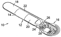
도 1에는 WO2010/070332에 개시된 신경근육 자극 장치(10)가 도시되어 있다. 상기 장치는 유연한, 비신축성 열가소성 탄성중합체(elastomer) 기판(12)을 포함하며, 이는 일단부에 세장형 돌출부(tongue)(14)와 타단부에 성형된 오목부(recess)(16)를 포함한다. FIG. 1 shows a
상기 돌출부(14)에 양전극(18)과 음전극(20)이 인쇄된다. 양전극이 음전극보다 약간 더 크다. 각 전극은 전극으로부터 오목부(16) 내에 위치한 각각의 접점(26, 28)으로 이어지는 도전성 트랙(22, 24)를 포함한다. The
도면들에 도시되지 않았지만, 원치 않는 전류의 누설을 방지하기 위해, 양의 트랙(22)과 음전극(20) 사이에 절연 스트립이 배치되어 있으며, 돌출부의 가장자리에 유사한 스트립들이 배치된다. Although not shown in the drawings, insulating strips are disposed between the
상기 오목부(16) 내부에 전지(미도시)와, 전극들을 제어하기 위해 적합한 회로를 포함하는 PCB(미도시)가 배치된다. 이는 도전성 트랙들(22, 24)과 접점들(26, 28)과 함께 완전한 회로를 형성한다. 그 다음에, 플라스틱 커버가 오목부(16) 위에 소닉 용접되어 구성부품들을 밀봉한다. 그 다음에, 겔(gel) 층이 전체 장치(10) 위에 배치되며; 이는 사용자의 사지(limb)와의 전기적 접촉을 제공하고 상기 장치가 사용자에게 부착된 상태로 유지되도록 돕는다. 상기 겔은 박리식 보호층에 의해 운반 시 보호될 수 있다. A PCB (not shown) including a battery (not shown) and a circuit suitable for controlling the electrodes is disposed in the
상기 오목부(16)의 외면은 일체형 다이어프램 버턴(30)과 LED를 디스플레이하기 위한 개구(32)로 형성된다. 상기 버턴(30)은 장치를 작동시키기 위해 배터리 하우징 또는 PCB 상의 대응되는 버턴에 접촉하도록 구성된다. 상기 개구(32)는 장치가 작동중인지 여부를 나타내는 LED를 디스플레이 한다.The outer surface of the
여기서 설명되는 바와 같이, 스위치 구성을 통합하기 위해, 상기 장치(10)는 다수의 방식으로 변경된다. 상기 양전극(18)과 음전극(20)은 BoPET(예컨대, Mylar(RTM)) 유연성 기판상에 인쇄되며, 이는 그 자체가 세장형 돌출부(14)에 부착되어 있다. 상기 기판은 또한 상기 전극들을 PCB 상의 제어 회로에 연결하기 위한 도전성 트랙들을 가지고 있다. 그리고, 설명되는 바와 같이, 상기 버턴(30)은 스스로 배터리 하우징 또는 PCB 상의 대응되는 버턴에 접촉하지 않는다. As described herein, to integrate the switch configuration, the
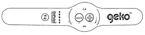
외부에서 본 대체 가능한 장치가 도 5와 6에 도시되어 있다. 이 장치는 도 1에 도시된 장치와 작동면에서 일반적으로 유사하지만, 오목부/인클로저가 유연성 돌출부의 중심쪽으로 배치된다는 점에서 약간 다른 구성을 가진다. 도 5에서, 상기 장치의 상면에 두 개의 돔-형상의 푸시 버턴들이 있는 것을 볼 수 있다. 도 6에는 상기 장치의 저면이 도시된다. Alternative devices viewed from the outside are shown in Figs. 5 and 6. Fig. The device is generally similar in operation to the device shown in Figure 1, but has a slightly different configuration in that the recess / enclosure is disposed towards the center of the flexible protrusion. In Figure 5, it can be seen that there are two dome-shaped pushbuttons on the top of the device. The bottom of the device is shown in Fig.
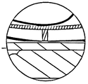
도 2는 본 발명의 실시예에 따른 도 5와 6의 변경된 장치들의 단면을 보여준다. 이 도면은 인클로저(enclosure)(도 1의 오목부(16)에 대응됨)를 형성하는 하우징(30)을 보여준다. 상기 하우징(30)은, 하우징의 상측 부분과 하측 부분을 형성하는 두 개의 사출 성형 플라스틱 부분들(32, 34)로 형성된다. 상기 세장형 돌출부(14)는 상기 하우징(30)의 양단부에 형성된 플랜지들에 연결될 수 있다. 상기 하우징(30) 내부에 전지(36)와 PCB(38)가 위치한다. 상기 하우징의 두 개의 부분들은 수밀성 밀봉을 형성하기 위해, 예를 들어, 초음파 용접에 의해 함께 용접된다. Figure 2 shows a cross section of the modified apparatus of Figures 5 and 6 according to an embodiment of the present invention. This view shows the housing 30 forming an enclosure (corresponding to the
상기 하우징(30)은 그 내부에 상측 및 하측 부분들(32, 34) 사이에 형성된 돌출부 경로(40)를 포함하며, 상기 경로는 상기 부분들 사이의 갭(gap)으로서 형성된다. 이 경로(40) 내부에 마일러(Mylar) 유연성 기판(42)이 배치되며, 이는 하우징을 넘어서 돌출부(14)에 고정될 수 있다. 상기 기판(42)의 (도면에 도시된 바에 따른) 하면에 기판을 PCB(30)와 전지(36)에 연결하기 위한 한 쌍의 전극과 전기 도전성 트랙들이 인쇄된다. 구불구불한 경로(40)는 기판(42)을 장력하에서 유지하는 역할을 하며, 그럼으로써 기판(42)은 PCB(38) 위에 매달려 있고 하우징에 대해 이동하지 않는다. The housing 30 includes a protruding
상기 하우징(30)의 상측 부분(32)의 상부 외면에 한 쌍의 스위치들이 유연한 둘출된 돔(44)의 형태로 형성되며; 각각의 돔(44)은 내부로 연장된 핀(46)을 포함한다. 상기 돔(44)과 핀(46)은 상기 하우징 내부에 일체로 형성된다. 상기 돔(440은 특히 탄성 재료로 형성됨으로써, 압력하에서 변형되지만, 그 압력이 제거되었을 때 원래 위치로 복귀한다. 본 발명의 몇몇의 실시예들에서, 상기 돔은 단순히 변형 가능한 재료로 형성될 수 있으며, 그럼으로써 그들의 원래 위치로 되돌아가지 않는다. A pair of switches are formed on the upper outer surface of the
상기 스위치들을 작동시키기 위해, (도 3과 4에 도시된 바와 같이) 사용자는 손가락으로 상기 돔(44)에 압력을 가하게 된다. 상기 돔(44)은 변형되고 하우징(30) 내부로 연장되며; 이는 상기 핀(46)이 기판(42)과 접촉되도록 강제하고, 이에 따라 기판(42)은 PCB(38)와 접촉하도록 가압된다. 따라서, 상기 기판(42) 상에 인쇄된 도전성 트랙의 일부는 PCB 상에 형성된 도전성 부분과 접촉하게 되고, 그럼으로써 완전한 전기 회로를 형성하고 스위치를 닫는다. 사용자가 스위치를 해제할 때, 플라스틱 재료의 탄성에 의해 돔(44)은 원래의 위치로 되돌아가게 되며, 상기 기판(42) 내의 장력도 스프링으로서 작용함으로써 돔의 복귀를 돕는다. 이는 기판(42)을 PCB(38)로부터 분리시킴으로써, 스위치가 열리게 된다. 상기 스위치의 돔 형상은, 상기 기판의 탄성 및 핀의 존재와 조합되어, 함께 사용자에게 촉각 피드백(tectile feedback)을 제공한다. To actuate the switches, the user applies pressure to the
어떤 실시예에서, 상기 돔(44)은 탄성이 없을 수 있으며, 그럼으로써 상기 스위치는 닫힌 상태로 유지될 것이고, 이는 1회용 버턴 또는 회로를 위해 사용될 수 있다. In some embodiments, the
상기 스위치가 신경근육 자극을 위한 의료 장치의 맥락에서 설명되었다 하더라도, 그 적용 가능성은 이에 제한되지 않는다는 것은 명백할 것이다. 특히, 상기 스위치 구성은, 비교적 적은 동작 부품이 있으며, 스위치는 전자 장치 내에 사용될 수 있는 구성부품들(케이싱, 기판, PCB)로 형성될 수 있다는 점에서, 이상적으로 저비용의 1회용 적용에 적합하다. 또한, 케이싱은 밀봉되어 대체로 수밀성 장치가 될 수 있다. 본 발명자는 특히 상기 스위치는 그 중에서도 휴대용 전화기, 시계, 제어 패널, 또는 키보드에서 이점이 있을 것으로 예상한다.Although the switch has been described in the context of a medical device for neuromuscular stimulation, it will be clear that its applicability is not so limited. In particular, the switch configuration is ideally suited for low-cost, single-use applications in that it has relatively few moving parts and the switch can be formed of components (casing, substrate, PCB) that can be used in an electronic device . Also, the casing may be sealed to be a generally watertight device. The present inventors especially anticipate that the switch will be advantageous, among other things, in a portable telephone, a clock, a control panel, or a keyboard.
Claims (17)
전기 전도성 경로를 가지는 유연성 전기 절연 기판;을 포함하며;
상기 유연성 기판의 적어도 부분은, 상기 부분이 PCB에 인접하지만 PCB로부터 이격되도록 상기 케이싱에 의해 유지되고;
상기 일체형 유연성 부분은 상기 케이싱의 내부로 휘어질 때, 상기 유연성 기판의 상기 부분을 상기 PCB와 접촉하도록 강제함으로써, 상기 전기 전도성 경로가 상기 전기 접점과 접촉함에 의하여 전기 회로가 완성되는, 전자 장치. CLAIMS What is claimed is: 1. A plastic casing defining an interior and an exterior, the interior of which includes a printed circuit board (PCB) having electrical contacts, the casing including an outer integral flexible portion capable of flexing into the interior of the casing;
A flexible electrically insulating substrate having an electrically conductive path;
Wherein at least a portion of the flexible substrate is held by the casing such that the portion is adjacent to the PCB but spaced from the PCB;
Wherein the integral flexible portion is forced into contact with the PCB when the portion of the flexible substrate is bent into the casing such that the electrically conductive path contacts the electrical contact to complete the electrical circuit.
상기 외부 일체형 유연성 부분은 탄성이 있으며, 상기 일체형 유연성 부분에 힘이 인가될 때 상기 케이싱 내부로 휘어지고, 힘이 인가되지 않을 때, 더 이상 그렇게 휘어지지 않는, 전자 장치.The method according to claim 1,
Wherein the externally integral flexible portion is resilient and flexes into the casing when a force is applied to the integral flexible portion and is no longer so bent when no force is applied.
상기 외부 일체형 유연성 부분은 돔(dome) 형태로 형성되는, 전자 장치.3. The method according to claim 1 or 2,
Wherein the outer integral flexible portion is formed in the form of a dome.
상기 유연성 기판의 부분은 상기 케이싱에 의해 장력하에서 유지되는, 전자 장치.The apparatus according to any one of the preceding claims,
Wherein a portion of the flexible substrate is held under tension by the casing.
상기 유연성 기판은 상기 케이싱 내부에 형성된 구불구불한 경로 내부에 배치됨으로써, 상기 기판이 상기 케이싱에 의해 유지되는, 전자 장치.The apparatus according to any one of the preceding claims,
Wherein the flexible substrate is disposed within a serpentine path formed within the casing such that the substrate is held by the casing.
상기 케이싱은 함께 고정되는 두 개의 부분들로 형성되고, 상기 구불구불한 경로는 상기 두 개의 부분들 사이에 형성되는, 전자 장치.6. The method of claim 5,
Wherein the casing is formed of two portions that are secured together, and wherein the serpentine path is formed between the two portions.
상기 유연성 기판은 상기 케이싱을 넘어서 연장되는, 전자 장치.The apparatus according to any one of the preceding claims,
Wherein the flexible substrate extends beyond the casing.
상기 유연성 기판은 중합체 기판인, 전자 장치.The apparatus according to any one of the preceding claims,
Wherein the flexible substrate is a polymer substrate.
상기 유연성 기판은 이축-연신 폴리에틸렌 테레프탈레이트(biaxially-oriented polyethylene terephthalate) 필름인, 전자 장치.9. The method of claim 8,
Wherein the flexible substrate is a biaxially-oriented polyethylene terephthalate film.
상기 일체형 유연성 부분은, 상기 유연성 기판을 상기 PCB와 접촉하도록 강제하는데 도움을 주기 위해 크기와 형상이 부여된 내부 돌기를 포함하는, 전자 장치.The apparatus according to any one of the preceding claims,
Wherein the integral flexible portion includes an inner protrusion sized and shaped to assist in forcing the flexible substrate into contact with the PCB.
상기 케이싱은 전지를 더 포함하는, 전자 장치.The apparatus according to any one of the preceding claims,
Wherein the casing further comprises a battery.
다수의 외부 일체형 유연성 부분들과, 상기 PCB 상에 대응되는 다수의 전기 접점들을 포함하는, 전자 장치.The apparatus according to any one of the preceding claims,
A plurality of external integral flexible portions, and a plurality of electrical contacts corresponding to the PCB.
상기 케이싱은 수분의 침투에 대해 실질적으로 밀봉되는, 전자 장치.The apparatus according to any one of the preceding claims,
Wherein the casing is substantially sealed against penetration of moisture.
상기 케이싱은 사출 성형되는, 전자 장치.The apparatus according to any one of the preceding claims,
Wherein the casing is injection molded.
상기 전자 장치는 의료 장치인, 전자 장치.The apparatus according to any one of the preceding claims,
Wherein the electronic device is a medical device.
상기 의료 장치는 전기적 신경근육 자극기인, 전자 장치.16. The method of claim 15,
Wherein the medical device is an electrical neuromuscular stimulator.
전기 전도성 경로를 가지는 유연성 전기 절연 기판;을 포함하며;
상기 유연성 기판의 적어도 부분은, 상기 부분이 PCB에 인접하지만 PCB로부터 이격되도록 상기 케이싱에 의해 유지되고;
상기 일체형 유연성 부분은 상기 케이싱의 내부로 휘어질 때, 상기 유연성 기판의 상기 부분을 상기 PCB와 접촉하도록 강제함으로써, 상기 전기 전도성 경로가 상기 전기 접점과 접촉함에 의하여 전기 회로가 완성되는, 전기 스위치.CLAIMS What is claimed is: 1. A plastic casing defining an interior and an exterior, the interior of which includes a printed circuit board (PCB) having electrical contacts, the casing including an outer integral flexible portion capable of flexing into the interior of the casing;
A flexible electrically insulating substrate having an electrically conductive path;
Wherein at least a portion of the flexible substrate is held by the casing such that the portion is adjacent to the PCB but spaced from the PCB;
Wherein the integral flexible portion is forced into contact with the PCB when the flexible portion is flexed into the casing such that the electrically conductive path contacts the electrical contact to complete the electrical circuit.
Applications Claiming Priority (3)
| Application Number | Priority Date | Filing Date | Title |
|---|---|---|---|
| GB201500163 | 2015-01-07 | ||
| GB1500163.9 | 2015-01-07 | ||
| PCT/GB2016/050032 WO2016110705A1 (en) | 2015-01-07 | 2016-01-07 | Switch |
Publications (2)
| Publication Number | Publication Date |
|---|---|
| KR20170097784A true KR20170097784A (en) | 2017-08-28 |
| KR102487596B1 KR102487596B1 (en) | 2023-01-11 |
Family
ID=55168296
Family Applications (1)
| Application Number | Title | Priority Date | Filing Date |
|---|---|---|---|
| KR1020177021039A Active KR102487596B1 (en) | 2015-01-07 | 2016-01-07 | switch |
Country Status (8)
| Country | Link |
|---|---|
| US (1) | US10478611B2 (en) |
| EP (1) | EP3243208B1 (en) |
| JP (1) | JP6976853B2 (en) |
| KR (1) | KR102487596B1 (en) |
| CN (1) | CN107206231B (en) |
| CA (1) | CA2973173C (en) |
| ES (1) | ES2819527T3 (en) |
| WO (1) | WO2016110705A1 (en) |
Families Citing this family (2)
| Publication number | Priority date | Publication date | Assignee | Title |
|---|---|---|---|---|
| CN107431156B (en) | 2015-01-07 | 2020-09-01 | 斯凯医疗技术有限公司 | Tamper-proof battery case |
| US10548235B1 (en) * | 2018-04-09 | 2020-01-28 | Rockwell Collins, Inc. | Harsh environment key panel and bezel structures |
Citations (8)
| Publication number | Priority date | Publication date | Assignee | Title |
|---|---|---|---|---|
| JPS57128421A (en) * | 1980-12-15 | 1982-08-10 | Advanced Circuit Tech | Electric switch assembly and method of producing same |
| DE3716379A1 (en) * | 1986-05-16 | 1987-11-19 | Sharp Kk | Electronic apparatus having a keyboard |
| JPH0472524U (en) * | 1990-11-07 | 1992-06-25 | ||
| JPH05101743A (en) * | 1991-10-07 | 1993-04-23 | Koden Electron Co Ltd | Pressing switch device |
| JP2004031185A (en) * | 2002-06-27 | 2004-01-29 | Yazaki Corp | Thin switch |
| JP2006345484A (en) * | 2005-05-12 | 2006-12-21 | Matsushita Electric Ind Co Ltd | Transmitter |
| JP2012512682A (en) * | 2008-12-19 | 2012-06-07 | スカイ メディカル テクノロジー リミテッド | treatment |
| JP2013062071A (en) * | 2011-09-12 | 2013-04-04 | Nitto Denko Corp | Push button switch and adhesive tape for push button switch |
Family Cites Families (21)
| Publication number | Priority date | Publication date | Assignee | Title |
|---|---|---|---|---|
| US4070821A (en) | 1976-03-22 | 1978-01-31 | Hughes Aircraft Company | Electric watch battery contact spring |
| US4190748A (en) * | 1977-01-31 | 1980-02-26 | Rogers Corporation | Keyboard switch assembly |
| US4322587A (en) * | 1979-12-06 | 1982-03-30 | Rogers Corporation | Keyboard device |
| US4323740A (en) * | 1980-02-04 | 1982-04-06 | Rogers Corporation | Keyboard actuator device and keyboard incorporating the device |
| CH660109GA3 (en) | 1985-06-25 | 1987-03-31 | ||
| AU8118587A (en) * | 1986-11-17 | 1988-05-19 | Exicom Australia Pty Limited | Improved membrane keyboard |
| FR2621403B1 (en) | 1987-10-05 | 1992-12-11 | Fuji Photo Film Co Ltd | PHOTOGRAPHIC FILM MODULE HAVING AN OPTICAL LENS |
| US5752087A (en) | 1997-05-20 | 1998-05-12 | Eastman Kodak Company | One-time-use camera with front and rear cover parts that can be bent apart to permit battery to drop out of chamber |
| US6049145A (en) | 1997-07-07 | 2000-04-11 | Motorola, Inc. | Tamper proof safety circuit |
| EP1054316B1 (en) | 1999-05-15 | 2006-10-11 | Scheidt & Bachmann Gmbh | Security device for electronic circuits against unauthorised access |
| JP2002257960A (en) | 2001-03-01 | 2002-09-11 | Citizen Watch Co Ltd | Structure of solar clock |
| CA2389950A1 (en) * | 2002-06-28 | 2003-03-09 | Robert Gagnon | How to produce crude petroleum from organic wastes by a process called petrolisation |
| US7764936B2 (en) * | 2005-05-12 | 2010-07-27 | Panasonic Corporation | Dust and water resistant electronics enclosure |
| JP3875716B1 (en) | 2006-05-23 | 2007-01-31 | 株式会社バンダイ | Battery box and battery built-in toy |
| JP5115479B2 (en) * | 2006-10-12 | 2013-01-09 | 日本電気株式会社 | Operation key structure |
| GB2487758A (en) | 2011-02-03 | 2012-08-08 | Isansys Lifecare Ltd | Health monitoring electrode assembly |
| US8777115B2 (en) * | 2012-07-13 | 2014-07-15 | Syscard Innovations Inc. | Card switch |
| JP6107039B2 (en) * | 2012-10-04 | 2017-04-05 | ミツミ電機株式会社 | Switch manufacturing method |
| US20140295333A1 (en) * | 2013-03-29 | 2014-10-02 | Xerox Corporation | Image forming system |
| EP2986339A4 (en) | 2013-04-19 | 2016-12-21 | Oculeve Inc | DEVICES AND METHODS FOR NASAL STIMULATION |
| CN107431156B (en) | 2015-01-07 | 2020-09-01 | 斯凯医疗技术有限公司 | Tamper-proof battery case |
-
2016
- 2016-01-07 ES ES16700661T patent/ES2819527T3/en active Active
- 2016-01-07 WO PCT/GB2016/050032 patent/WO2016110705A1/en not_active Ceased
- 2016-01-07 CN CN201680005312.9A patent/CN107206231B/en active Active
- 2016-01-07 CA CA2973173A patent/CA2973173C/en active Active
- 2016-01-07 US US15/540,838 patent/US10478611B2/en active Active
- 2016-01-07 JP JP2017535910A patent/JP6976853B2/en active Active
- 2016-01-07 KR KR1020177021039A patent/KR102487596B1/en active Active
- 2016-01-07 EP EP16700661.8A patent/EP3243208B1/en active Active
Patent Citations (10)
| Publication number | Priority date | Publication date | Assignee | Title |
|---|---|---|---|---|
| JPS57128421A (en) * | 1980-12-15 | 1982-08-10 | Advanced Circuit Tech | Electric switch assembly and method of producing same |
| DE3716379A1 (en) * | 1986-05-16 | 1987-11-19 | Sharp Kk | Electronic apparatus having a keyboard |
| JPH0472524U (en) * | 1990-11-07 | 1992-06-25 | ||
| JPH05101743A (en) * | 1991-10-07 | 1993-04-23 | Koden Electron Co Ltd | Pressing switch device |
| JP2004031185A (en) * | 2002-06-27 | 2004-01-29 | Yazaki Corp | Thin switch |
| US20040026222A1 (en) * | 2002-06-27 | 2004-02-12 | Yazaki Corporation | Slim switch |
| JP2006345484A (en) * | 2005-05-12 | 2006-12-21 | Matsushita Electric Ind Co Ltd | Transmitter |
| JP2012512682A (en) * | 2008-12-19 | 2012-06-07 | スカイ メディカル テクノロジー リミテッド | treatment |
| JP2013062071A (en) * | 2011-09-12 | 2013-04-04 | Nitto Denko Corp | Push button switch and adhesive tape for push button switch |
| EP2757566A1 (en) * | 2011-09-12 | 2014-07-23 | Nitto Denko Corporation | Push-button switch and adhesive tape for push-button switch |
Also Published As
| Publication number | Publication date |
|---|---|
| JP6976853B2 (en) | 2021-12-08 |
| ES2819527T3 (en) | 2021-04-16 |
| CA2973173C (en) | 2023-07-18 |
| US10478611B2 (en) | 2019-11-19 |
| CN107206231B (en) | 2021-01-05 |
| US20180001076A1 (en) | 2018-01-04 |
| JP2018506819A (en) | 2018-03-08 |
| CN107206231A (en) | 2017-09-26 |
| WO2016110705A1 (en) | 2016-07-14 |
| CA2973173A1 (en) | 2016-07-14 |
| EP3243208B1 (en) | 2020-06-17 |
| KR102487596B1 (en) | 2023-01-11 |
| EP3243208A1 (en) | 2017-11-15 |
Similar Documents
| Publication | Publication Date | Title |
|---|---|---|
| US5332944A (en) | Environmentally sealed piezoelectric switch assembly | |
| US10722705B2 (en) | Nerve electrical stimulation device | |
| WO2017047519A1 (en) | Elastic wiring member | |
| JP2014087669A (en) | Sexual stimulation device | |
| JP6904356B2 (en) | Actuators, actuator modules, endoscopes, endoscope modules and control methods | |
| US20170136228A1 (en) | Cutaneous device, in particular a pulse generator for electrical stimulation | |
| KR102487596B1 (en) | switch | |
| AU2003237021A1 (en) | Electrical switch | |
| EP3679595B1 (en) | A button assembly | |
| US20180026240A1 (en) | Tamper proof battery enclosure | |
| JP2723258B2 (en) | Small electrical stimulator | |
| KR101610794B1 (en) | Electrostatic force based actuator including conductive polymer layer | |
| US10258787B2 (en) | Cutaneous medical device comprising a main part and including a base and a removable electrode | |
| JP6973325B2 (en) | Electronics | |
| JP6950645B2 (en) | Electronics | |
| JP7035901B2 (en) | Electronics | |
| CN219323655U (en) | Functional component and physiotherapy equipment using same | |
| JP2020028189A (en) | Electronic apparatus | |
| KR20170110339A (en) | Haptic module using piezoelectric element | |
| KR20250143590A (en) | Haptic actuator module and assembly using electrostatic attraction and pin stimulation | |
| JP2020028162A (en) | Electronic apparatus | |
| RU95178U1 (en) | PIEZO SWITCH WITH LIGHT RING INDICATION | |
| KR20260036156A (en) | Variable electrical therapy apparatus | |
| CN117752522A (en) | Functional component and physiotherapy equipment using same | |
| JP5228901B2 (en) | Push-on switch |
Legal Events
| Date | Code | Title | Description |
|---|---|---|---|
| PA0105 | International application |
St.27 status event code: A-0-1-A10-A15-nap-PA0105 |
|
| PG1501 | Laying open of application |
St.27 status event code: A-1-1-Q10-Q12-nap-PG1501 |
|
| P11-X000 | Amendment of application requested |
St.27 status event code: A-2-2-P10-P11-nap-X000 |
|
| P13-X000 | Application amended |
St.27 status event code: A-2-2-P10-P13-nap-X000 |
|
| R15-X000 | Change to inventor requested |
St.27 status event code: A-3-3-R10-R15-oth-X000 |
|
| R16-X000 | Change to inventor recorded |
St.27 status event code: A-3-3-R10-R16-oth-X000 |
|
| A201 | Request for examination | ||
| PA0201 | Request for examination |
St.27 status event code: A-1-2-D10-D11-exm-PA0201 |
|
| E902 | Notification of reason for refusal | ||
| PE0902 | Notice of grounds for rejection |
St.27 status event code: A-1-2-D10-D21-exm-PE0902 |
|
| E13-X000 | Pre-grant limitation requested |
St.27 status event code: A-2-3-E10-E13-lim-X000 |
|
| P11-X000 | Amendment of application requested |
St.27 status event code: A-2-2-P10-P11-nap-X000 |
|
| P13-X000 | Application amended |
St.27 status event code: A-2-2-P10-P13-nap-X000 |
|
| E701 | Decision to grant or registration of patent right | ||
| PE0701 | Decision of registration |
St.27 status event code: A-1-2-D10-D22-exm-PE0701 |
|
| PR0701 | Registration of establishment |
St.27 status event code: A-2-4-F10-F11-exm-PR0701 |
|
| PR1002 | Payment of registration fee |
St.27 status event code: A-2-2-U10-U12-oth-PR1002 Fee payment year number: 1 |
|
| PG1601 | Publication of registration |
St.27 status event code: A-4-4-Q10-Q13-nap-PG1601 |
|
| PR1001 | Payment of annual fee |
St.27 status event code: A-4-4-U10-U11-oth-PR1001 Fee payment year number: 4 |
|
| U11 | Full renewal or maintenance fee paid |
Free format text: ST27 STATUS EVENT CODE: A-4-4-U10-U11-OTH-PR1001 (AS PROVIDED BY THE NATIONAL OFFICE) Year of fee payment: 4 |