KR20170120008A - Brake control device and motor calibration method of the brake control device - Google Patents
Brake control device and motor calibration method of the brake control device Download PDFInfo
- Publication number
- KR20170120008A KR20170120008A KR1020160048441A KR20160048441A KR20170120008A KR 20170120008 A KR20170120008 A KR 20170120008A KR 1020160048441 A KR1020160048441 A KR 1020160048441A KR 20160048441 A KR20160048441 A KR 20160048441A KR 20170120008 A KR20170120008 A KR 20170120008A
- Authority
- KR
- South Korea
- Prior art keywords
- phase
- position value
- motor
- value
- phase motor
- Prior art date
- Legal status (The legal status is an assumption and is not a legal conclusion. Google has not performed a legal analysis and makes no representation as to the accuracy of the status listed.)
- Withdrawn
Links
Images



Classifications
-
- B—PERFORMING OPERATIONS; TRANSPORTING
- B60—VEHICLES IN GENERAL
- B60T—VEHICLE BRAKE CONTROL SYSTEMS OR PARTS THEREOF; BRAKE CONTROL SYSTEMS OR PARTS THEREOF, IN GENERAL; ARRANGEMENT OF BRAKING ELEMENTS ON VEHICLES IN GENERAL; PORTABLE DEVICES FOR PREVENTING UNWANTED MOVEMENT OF VEHICLES; VEHICLE MODIFICATIONS TO FACILITATE COOLING OF BRAKES
- B60T13/00—Transmitting braking action from initiating means to ultimate brake actuator with power assistance or drive; Brake systems incorporating such transmitting means, e.g. air-pressure brake systems
- B60T13/74—Transmitting braking action from initiating means to ultimate brake actuator with power assistance or drive; Brake systems incorporating such transmitting means, e.g. air-pressure brake systems with electrical assistance or drive
-
- B—PERFORMING OPERATIONS; TRANSPORTING
- B60—VEHICLES IN GENERAL
- B60T—VEHICLE BRAKE CONTROL SYSTEMS OR PARTS THEREOF; BRAKE CONTROL SYSTEMS OR PARTS THEREOF, IN GENERAL; ARRANGEMENT OF BRAKING ELEMENTS ON VEHICLES IN GENERAL; PORTABLE DEVICES FOR PREVENTING UNWANTED MOVEMENT OF VEHICLES; VEHICLE MODIFICATIONS TO FACILITATE COOLING OF BRAKES
- B60T13/00—Transmitting braking action from initiating means to ultimate brake actuator with power assistance or drive; Brake systems incorporating such transmitting means, e.g. air-pressure brake systems
- B60T13/74—Transmitting braking action from initiating means to ultimate brake actuator with power assistance or drive; Brake systems incorporating such transmitting means, e.g. air-pressure brake systems with electrical assistance or drive
- B60T13/741—Transmitting braking action from initiating means to ultimate brake actuator with power assistance or drive; Brake systems incorporating such transmitting means, e.g. air-pressure brake systems with electrical assistance or drive acting on an ultimate actuator
-
- H—ELECTRICITY
- H02—GENERATION; CONVERSION OR DISTRIBUTION OF ELECTRIC POWER
- H02P—CONTROL OR REGULATION OF ELECTRIC MOTORS, ELECTRIC GENERATORS OR DYNAMO-ELECTRIC CONVERTERS; CONTROLLING TRANSFORMERS, REACTORS OR CHOKE COILS
- H02P6/00—Arrangements for controlling synchronous motors or other dynamo-electric motors using electronic commutation dependent on the rotor position; Electronic commutators therefor
- H02P6/14—Electronic commutators
- H02P6/16—Circuit arrangements for detecting position
Landscapes
- Engineering & Computer Science (AREA)
- Transportation (AREA)
- Mechanical Engineering (AREA)
- Power Engineering (AREA)
- Braking Systems And Boosters (AREA)
- Regulating Braking Force (AREA)
Abstract
본 발명의 실시 예에 따른 브레이크 제어 장치는 휠의 제동을 위한 유체를 공급하는 액추에이터를 구동시키는 3상 모터, 3상 모터 회전시 모터의 회전 위치를 산출하는 위치센서, 3상 모터 및 위치센서를 제어하는 전자제어유닛를 포함하고, 전자제어유닛은 3상 모터를 여자시켜 위치센서에 의하여 산출된 3상 모터의 위치값을 3상 모터의 극수를 기초로 보정한다.The brake control apparatus according to an embodiment of the present invention includes a three-phase motor for driving an actuator for supplying a fluid for braking a wheel, a position sensor for calculating a rotational position of the motor when the three-phase motor rotates, And the electronic control unit excites the three-phase motor to correct the position value of the three-phase motor calculated by the position sensor based on the number of poles of the three-phase motor.
Description
본 발명은 브레이크 제어 장치에 관한 것으로 구체적으로는 브레이크 제어 장치의 모터를 초기 검증하고 이를 기초로 모터의 위치값을 보정하는 방법에 관한 것이다.The present invention relates to a brake control apparatus, and more particularly, to a method of initially verifying a motor of a brake control apparatus and correcting a position value of the motor based on the initial verification.
차량에는 필수적으로 제동장치 즉, 차량용 브레이크 장치가 설치된다. 이러한 차량용 브레이크 장치는 달리고 있는 차량의 속도를 줄이거나 정지시키는 기능을 하는 장치를 말한다.The vehicle is essentially provided with a braking device, that is, a vehicle braking device. Such a vehicle braking device refers to a device that functions to reduce or stop the speed of a running vehicle.
종래의 차량용 브레이크 장치에는 엔진의 흡입압을 사용해서 제동력이 발생하는 지공 브레이크와 유압을 사용해서 제동력을 발생하는 유압 브레이크가 있다.BACKGROUND ART [0002] Conventional vehicular brake devices include a pneumatic brake that generates a braking force by using the suction pressure of an engine, and a hydraulic brake that generates a braking force by using hydraulic pressure.
진공 브레이크는 진공 부스터에서 차량 엔진의 흡입압과 대기압의 압력차를 이용하여 작은 힘으로 큰 제동력을 발휘할 수 있도록 하는 장치이지만, 차량의 정차 시에도 진공 형성을 위해서 엔진을 상시구동해야 하므로 연비 효율이 저감되는 문제점이 있어 유압 브레이크가 도입되었다.The vacuum brake is a device that allows the vacuum booster to exert a large braking force with a small force using the suction pressure of the vehicle engine and the atmospheric pressure difference. However, since the engine must be driven at all times for vacuum formation even when the vehicle is stopped, There is a problem that the hydraulic brake is introduced.
한편, 유압 브레이크의 한 종류인 전자제어 유압 브레이크 시스템은 운전자가 페달을 밟으면 전자제어유닛이 이를 감지하고 유압을 마스터 실린더에 공급함으로써, 각 바퀴의 휠 실린더에 제동 유압을 전달하여 제동력을 발생하는 브레이크 시스템이다. On the other hand, an electronically controlled hydraulic brake system, which is a type of hydraulic brake, is a brake system in which when the driver depresses a pedal, the electronic control unit senses this and the hydraulic pressure is supplied to the master cylinder to transmit the braking hydraulic pressure to the wheel cylinder of each wheel, System.
최근에는 전자제어 전자제어유닛(ECU) 시스템과 마스터 실린더 및 부스터를 하나의 시스템 유닛으로 통합함으로써 하나의 시스템 유닛을 통해 ABS 및 CBS 기능의 수행이 가능하고 사이즈 및 중량을 감소시킨 전동식 일체형 브레이크 제어 장치가 도입되고 있다.In recent years, an electronic control unit (ECU) system, a master cylinder and a booster are integrated into a single system unit, thereby enabling ABS and CBS functions to be performed through one system unit, Is introduced.
다만, 브레이크 제어 장치에 구비된 유도 전동기에는 직접적인 접점이 없기 때문에 모터의 이상을 파악하는데 어려움이 있고, 모터 위치 값을 구하기 위해서 홀 센서를 최소 2개가 필요하여 비용적 측면에서 불리하다.However, since there is no direct contact with the induction motor provided in the brake control device, it is difficult to grasp the abnormality of the motor, and at least two Hall sensors are required to obtain the motor position value, which is disadvantageous in terms of cost.
하기 선행문헌은 전자제어 유압 브레이크에 관한 것으로 유압제어유닛, 부스팅시린더, 마스터실린더, 페달, 시뮬레이터, 밸브에 관련된 기술이 개시되어 있으면 본 발명의 기술적 요지는 포함하고 있지 않다.The following prior art documents relate to electronically controlled hydraulic brakes and do not incorporate the technical gist of the present invention if techniques related to hydraulic control units, boosting cylinders, master cylinders, pedals, simulators and valves are disclosed.
본 발명의 실시 예에 따른 브레이크 제어 장치 및 브레이크 제어 장치의 모터 보정 방법은 다음과 같은 해결과제를 목적으로 한다.A brake control apparatus and a motor control method for a brake control apparatus according to embodiments of the present invention aim at the following problems.
첫째, 모터의 초기 상태를 검증할 수 있는 장치 및 방법을 제공하고자 한다.First, an apparatus and method for verifying an initial state of a motor are provided.
둘째, 모터를 여자시켜 모터의 각상의 위치값을 산출하는 장치 및 방법을 제공하고자 한다.Secondly, an apparatus and method for calculating a position value of each phase of a motor by exciting a motor are provided.
셋째, 산출된 위치값을 기초로 모터의 위치값을 보정할 수 있는 장치 및 방법을 제공하고자 한다.Third, an apparatus and method for correcting a position value of a motor based on a calculated position value are provided.
본 발명의 해결과제는 이상에서 언급된 것들에 한정하지 않으며, 언급되지 아니한 다른 해결과제들은 아래의 기재로부터 당해 기술분야에 있어서의 통상의 지식을 가진 자가 명확하게 이해할 수 있을 것이다.The present invention has been made in view of the above problems, and it is an object of the present invention to at least solve the problems in the conventional arts.
본 발명의 실시 예에 따른 브레이크 제어 장치는 휠의 제동을 위한 유체를 공급하는 액추에이터를 구동시키는 3상 모터, 3상 모터 회전시 모터의 회전 위치를 산출하는 위치센서, 3상 모터 및 위치센서를 제어하는 전자제어유닛를 포함하고, 전자제어유닛은 3상 모터를 여자시켜 위치센서에 의하여 산출된 3상 모터의 위치값을 3상 모터의 극수를 기초로 보정한다.The brake control apparatus according to an embodiment of the present invention includes a three-phase motor for driving an actuator for supplying a fluid for braking a wheel, a position sensor for calculating a rotational position of the motor when the three-phase motor rotates, And the electronic control unit excites the three-phase motor to correct the position value of the three-phase motor calculated by the position sensor based on the number of poles of the three-phase motor.
전자제어유닛은 미리 설정된 시간동안 상기 3상 모터의 각상을 여자시켜 각상의 위치값의 위치값을 산출하고, 각상의 위치값에 전기각 120도를 더하여 각상의 위치값을 상호 비교하고, 비교한 값이 미리 설정된값 미만인지 판단한다.The electronic control unit calculates the position value of each phase value by exciting each phase of the three-phase motor for a predetermined time, adds the electric angle of 120 degrees to the position value of each phase, compares the position value of each phase with each other, Value is less than a predetermined value.
전자제어유닛은 산출된 3상 모터 각상의 위치값 중 U상의 위치값을 기준으로 3상 모터 극 수를 2로 나눈 숫자만큼 시계방향 및 반시계방향 중 어느 방향을 기초로 모터회전을 하여 U상의 평균위치값을 산출한다.The electronic control unit rotates the motor based on the position value of the U phase among the position values of the calculated three-phase motors on the basis of the number of the three-phase motor poles divided by 2 in either clockwise or counterclockwise direction, The average position value is calculated.
전자제어유닛은 U상의 평균위치값을 U상의 위치값으로 설정하여 3상 모터에 적용한다.The electronic control unit applies the 3-phase motor by setting the average position value of the U phase to the U phase position value.
본 발명의 또 다른 실시 예에 따른 브레이크 제어 장치의 모터 위치값 보정 방법은 브레이크 제어 장치에 설치된 전자제어유닛이 3상 모터의 각상을 여자시키는 단계, 전자제어유닛에서 3상 모터의 각상의 위치값을 산출하는 단계, 3상 모터 각상의 위치값에 전기각 120도를 더하여 3상 모터 각상의 위치값을 상호 비교하는 단계, 3상 모터의 극수를 2로 나눈 숫자만큼 모터를 회전하여 3상 모터의 U상의 평균위치값을 산출하는 단계, U상의 평균위치값을 U상의 위치값으로 설정하는 단계를 포함한다.The method for correcting a motor position value of a brake control apparatus according to another embodiment of the present invention includes the steps of causing an electronic control unit provided in a brake control apparatus to energize each phase of a three-phase motor, Phase motor by adding the electric angle of 120 degrees to the position value of each phase of the three-phase motor, comparing the position values of the phases of the three-phase motor, rotating the motor by the number obtained by dividing the number of poles of the three- Calculating an average position value of the U phase of the U phase, and setting an average position value of the U phase to the U phase position value.
3상 모터의 각상을 여자시키는 단계는 브레이크 제어장치에 설치되어 3상 모터 각상의 위치값을 탐지하는 위치센서의 값에 대하여 안정화시키는 단계, 여자된 3상 모터의 각상의 전류를 검증하는 단계를 포함한다.The step of energizing each phase of the three-phase motor comprises the steps of stabilizing the value of the position sensor for detecting the position value of each phase of the three-phase motor provided in the brake control device, and verifying the current of each phase of the excited three- .
각상의 위치값을 산출하는 단계에는 3상 모터의 U상을 여자시켜 제1의 U상 위치값을 산출하는 단계, 3상 모터(20)의 V상을 여자시켜 V상 위치값을 산출하는 단계, 3상 모터(20)의 W상을 여자시켜 W상 위치값을 산출하는 단계, 3상 모터의 U상을 다시 여자시켜 제2의 U상 위치값을 산출하는 단계를 포함하고, 제1의 U상 위치값을 기초로 상기 V상 위치값, W상 위치값, 및 제2의 U상 위치값을 산출한다.Calculating the position value of each phase includes calculating a first U phase position value by exciting the U phase of the three-phase motor, calculating a V phase position value by exciting the V phase of the three-
각상의 위치값을 상호 비교하는 단계는 제1의 U상 위치값에 전기각 120도를 더하여 상기 V상 위치값과 비교하는 단계, V상 위치값에 전기각 120도를 더하여 W상 위치값과 비교하는 단계, W상 위치값에 전기각 120도를 더하여 제2의 U상 위치값과 비교하는 단계를 포함하고, 각상의 위치값을 비교한 값이 미리 설정된 제1값 이상일 경우 3상 모터(20)를 고장 처리한다.The step of comparing the position values of the respective phases comprises the steps of: adding a first U phase position value to the V phase position value by adding 120 degrees to the first U phase position value; adding the electrical angle of 120 degrees to the V phase position value; Comparing the W phase position value with a second U phase position value by adding an electrical angle of 120 degrees to the W phase position value, and when the value obtained by comparing the position value of each phase is equal to or greater than a preset first value, 20).
U상의 평균위치값을 산출하는 단계는 모터 회전 방향을 시계방향으로 하여 U 제1평균위치값을 산출하는 단계, 모터 회전 방향을 반시계방향으로 하여 U상의 제2평균위치값을 산출하는 단계를 포함하고 U상의 평균위치값은 제1평균위치값 및 제2평균위치값 중 적어도 어느 하나로 한다.Calculating the average position value on the U-phase includes calculating a first U-average position value in a clockwise direction of the motor rotation direction and calculating a second average position value on the U-axis in a counterclockwise direction And the average position value of the U phase is at least one of a first average position value and a second average position value.
설정된 U상의 위치값이 적용된 3상 모터의 RPM을 확인하는 단계를 더 포함한다. And confirming the RPM of the three-phase motor to which the position value on the set U is applied.
RPM을 확인하는 단계는 약계자 제어를 통하여 일정한 토크전류를 3상 모터에 인가하여 산출된 3상 모터의 RPM을 미리 설정된 PRM과 비교하는 단계, 타겟 RPM을 설정하여 3상 모터의 PRM이 타겟RPM에 도달하는 시간을 확인하는 단계를 포함한다.The step of verifying the RPM is a step of comparing the RPM of the three-phase motor calculated by applying a constant torque current to the three-phase motor through weak field control, with a preset PRM, setting the target RPM so that the PRM of the three- And the time required to reach the < RTI ID = 0.0 >
본 발명의 실시 예에 따른 브레이크 제어 장치 및 브레이크 제어 장치의 모터 보정 방법은 전자제어유닛을 통하여 모터의 각상을 여자시켜 각상의 위치값을 산출할 수 있다.The brake control apparatus and the motor correction method of the brake control apparatus according to the embodiment of the present invention can calculate the position value of each phase by exciting each phase of the motor through the electronic control unit.
또한, 전자제어유닛을 통하여 산출된 각상의 위치값을 상호 비교하므로 모터의 위치값 보정시 신뢰성을 높일 수 있다.Further, since the position values of the respective phases calculated through the electronic control unit are compared with each other, the reliability in correcting the position value of the motor can be improved.
또한, 위치값 보정을 통하여 브레이크 제어 장치의 효율을 높일 수 있다.Further, the efficiency of the brake control apparatus can be improved through the correction of the position value.
본 발명의 효과는 이상에서 언급된 것들에 한정되지 않으며, 언급되지 아니한 다른 효과들은 아래의 기재로부터 당해 기술분야에 있어서의 통상의 지식을 가진자가 명확하게 이해할 수 있을 것이다.The effects of the present invention are not limited to those mentioned above, and other effects not mentioned can be clearly understood by those skilled in the art from the following description.
도 1은 본 발명의 실시 예에 따른 브레이크 제어 장치를 도시한 회로도이다.
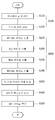
도 2는 본 발명의 또 다른 실시 예에 따른 브레이크 제어 장치의 모터 위치값 보정 방법을 도시한 플로우 차트이다
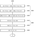
도 3은 본 발명의 또 다른 실시 예에 따른 브레이크 제어 장치의 모터 위치값 보정 방법의 각 상의 위치값을 산출하는 단계를 구체화한 플로우 차트이다.
도 4는 본 발명의 또 다른 실시 예에 따른 브레이크 제어 장치의 모터 위치값 보정 방법의 각 상의 위치값 상호 비교 단계를 구체화한 플로우 차트이다.
도 5는 본 발명의 또 다른 실시 예에 따른 브레이크 제어 장치의 모터 위치값 보정 방법의 PRM 확인 단계를 구체화한 플로우 차트이다.1 is a circuit diagram showing a brake control apparatus according to an embodiment of the present invention.
2 is a flowchart illustrating a method of correcting a motor position value of a brake control apparatus according to another embodiment of the present invention
3 is a flowchart illustrating a step of calculating a position value of each phase of the motor position correction method of the brake control apparatus according to another embodiment of the present invention.
4 is a flowchart illustrating a step of comparing position values of respective phases of a method of correcting a motor position value of a brake control apparatus according to another embodiment of the present invention.
5 is a flowchart illustrating a PRM check step of a method of correcting a motor position value of a brake control apparatus according to another embodiment of the present invention.
첨부된 도면을 참조하여 본 발명을 구체적으로 설명하겠다. 첨부된 도면은 본 발명의 사상을 쉽게 이해할 수 있도록 하기 위한 것일 뿐, 첨부된 도면에 의해 본 발명의 사항이 제한되는 것으로 해석되어서는 아니 됨을 유의해야 한다.The present invention will be described in detail with reference to the accompanying drawings. It is to be understood that the accompanying drawings are only for the purpose of facilitating understanding of the present invention and are not to be construed as limiting the scope of the present invention.
본 발명의 실시 예에 따른 브레이크 제어 장치는 3상 모터(20), 위치센서(70), 밸브(40), 전자제어유닛(50)를 포함한다.The brake control apparatus according to the embodiment of the present invention includes a three-
3상 모터(20)는 휠(60)의 제동을 위한 유체를 공급하는 액추에이터(10)를 구동시킨다.The three-
액추에이터(10)는 유체를 토출하고 흡입할 수 있게 실린더 및 피스톤으로 이루어진 펌프로 형성될 수 있다.The
밸브(40)는 유체의 흐름을 단속한다.The
따라서, 3상 모터와 밸브(40)의 오픈(Open)과 클로즈(Close) 상태에 따라 유압이 형성되어 유체는 액추에이터(20)에 및 휠(60)에 공급된다.Accordingly, hydraulic pressure is generated in accordance with the three-phase motor and the
위치센서(70)는 3상 모터(20) 회전시 3상 모터의 위치값을 산출한다.The
한편, 위치센서(70)의 노이즈 값을 제거하기 위하여 일정시간 동안 위치센서에서 산출되는 값이 수렴되도록 한 후 3상 모터의 위치값을 산출하는 것이 바람직하다.In order to remove the noise value of the
전자제어유닛(50)는 3상 모터(20), 밸브(40) 및 위치센서(70)를 제어한다.The
또한, 전자제어유닛(50)은 3상 모터(20)를 여자시켜 위치센서(70)에 의하여 산출된 3상 모터(20)의 위치값을 3상 모터(20)의 극수를 기초로 보정한다.The
또한, 전자제어유닛(50)은 3상 모터(20)의 각상을 여자시켜 각상의 위치값을 산출하고, 각상의 위치값에 전기각 120도를 더하여 각상의 위치값을 상호 비교하고, 비교한 값이 미리 설정된 값 미만인지 판단한다.Further, the
그 결과, 비교한 값이 설정된 값 이상이 될 경우 3상 모터(20)를 고장으로 판단할 수 있다.As a result, when the compared value is equal to or greater than the set value, the three-
따라서, 모터 초기 상태인 운전자가 시동을 걸고 운전 의지를 보였을 때 모터 각상의 위치를 검증하여 모터의 상태를 미리 파악하므로 운전자에게 경고등과 같은 수단으로 모터의 고장 여부를 효율적으로 알려줄 수 있다.Therefore, when the driver, who is in the initial state of the motor, starts the operation and shows the driver's intention, the position of the motor is verified to grasp the state of the motor in advance, so that the driver can be informed of the failure of the motor efficiently by means such as a warning lamp.
또한, 모터의 여자를 활용하여 모터의 고장 여부를 확인하므로 모터 구동 회로의 이상 여부도 용이 파악할 수 있다.In addition, by checking whether the motor is faulty by utilizing the excitation of the motor, it is easy to determine whether or not the motor driving circuit is abnormal.
각상을 여자시켜 위치값을 산출할 경우 U상, V상 W상, U상 순으로 여자를 시킨다.When each position is excited and the position value is calculated, the U phase, V phase, W phase, and U phase are excited.
따라서, 3상 모터(20)의 U상을 여자시켜 제1의 U상 위치값을 기준점 하고, V상을 여자시켜 V상의 위치값을 산출하고, 이후 W상을 여자시켜 W상의 위치값을 산출하고 다시 U상을 여자시켜 제2의 U상의 위치값을 산출할 수 있다.Therefore, the U phase of the three-
또한, 제1의 U상 위치값을 산출할 경우 산출된 값이 마이너스인지 플러스인지에 따라 3상 모터의 회전방향과 모터의 회전에 따른 액추에이터의 피스톤이 움직이는 방향을 알 수 있다.Further, when calculating the first U phase position value, the direction in which the piston of the actuator moves in accordance with the rotation direction of the three-phase motor and the rotation of the motor can be determined depending on whether the calculated value is negative or positive.
3상 모터(20) 회전 방향에 따라 피스톤이 실린더의 벽에 걸릴 경우 제1의 U상 위치값이 정상적인 값으로 나오지 않을 수 있으므로 제1의 U상 위치값을 기준점으로 형성한다.When the piston is caught by the wall of the cylinder according to the rotation direction of the three-
따라서, 3상 모터(20)의 상태를 검증할 경우 3상 모터(20)의 회전 방향을 액추에이터의 피스톤이 유체를 토출하도록 움직이는 방향인 어플라이 방향으로 설정하여 3상 모터(29)를 제어하는 것이 바람직하다.Accordingly, when verifying the state of the three-
각상의 위치값을 상호 비교하는 경우, 3상 모터(20)의 각상은 전기각 120도의 차이를 두고 형성하므로 다음과 같이 비교를 한다.When the position values of the respective phases are compared with each other, each phase of the three-
산출된 V상 위치값은 제1의 U상 위치값 전기각 120도를 더하여 비교하고, 산출된 W상 위치값은 V상 위치값에 전기각 120도를 더하여 비교하고, 산출된 제2의 U상의 위치값은 W상 위치값에 전기각 120도를 더하여 비교한다.The calculated V phase position value is compared with the first U phase position value electrical angle of 120 degrees, and the calculated W phase position value is compared with the V phase position value by adding the electrical angle of 120 degrees, and the calculated second U The position value on the W phase is compared with the W phase position value by adding the electric angle of 120 degrees.
따라서, 상기 비교된 값(절대값)이 전자제어유닛에 미리 설정된 값보다 작을 경우 정상적인 모터 상태로 파악하고, 클 경우 고장처리를 하여 운전자에게 경고할 수 있다.Therefore, if the compared value (absolute value) is smaller than a preset value in the electronic control unit, it can be grasped as a normal motor state.
또한, 이처럼 3상 모터 각 상의 위치를 상호 비교하는 것은 보정 전에 산출되는 위치값에 대하여 신뢰성을 높여 효율적으로 보정을 수행할 수 있다.Also, comparing the positions of the three-phase motor angles with each other can improve the reliability with respect to the position value calculated before the correction so that the correction can be performed efficiently.
미리 설정된 값은 전기각 10도로 형성할 수 있고, 3상 모터 설계 상태 및 외부 환경에 따라 변경할 수 있다.The preset value can be set to 10 degrees of electric angle, and can be changed according to the three-phase motor design state and the external environment.
도 1에 도시된 바와 같이 본 발명의 실시 예에 따른 브레이크 제어 장치는 3상 모터(20) 및 밸브(40)의 상태에 따라 휠(60) 및 액추에이터(10)에 유체를 공급할 수 있게 액추에이터에 연결되고 유체를 저장하는 리저버(30)를 더 포함할 수 있다.1, the brake control apparatus according to the embodiment of the present invention includes a three-
위 경우, 밸브는 액추에이터 및 액추에이터 사이에 구비될 수 있다.In the above case, the valve may be provided between the actuator and the actuator.
이에 따라, 휠(60) 혹은 액추에이터(10)에 공급된 유체에 상태에 따라 유체를 휠(60) 혹은 액추에이터(10)에 공급하거나 유체를 다시 회수하여 리저버(30)에 저장할 수 있다. Accordingly, the fluid supplied to the
또한, 본 발명의 실시 예에 따른 브레이크 제어 장치의 전자제어유닛(50)은 밸브(40)를 오픈시킨 후 3상 모터(20)를 여자시켜 3상 모터(20) 각상의 위치값을 산출할 수 있다.Further, the
따라서, 밸브(40)는 전자제어유닛에 제어에 의하여 오픈 될 때까지 평상시에는 클로즈 되는 NC(Normal Close) 솔레노이드 밸브로 형성할 수 있다.Therefore, the
위 경우, 밸브(40)를 오픈시켜 3상 모터(20)의 부하를 최소화함으로써 모터(20) 각상의 위치값을 정확하게 산출할 수 있다.In this case, by opening the
본 발명의 실시 예에 따른 브레이크 제어 장치의 전자제어유닛(50)은 산출된 상기 3상 모터(20) 각상의 위치값 중 U상의 위치값을 기준으로 상기 3상 모터(20) 극 수를 2로 나눈 숫자만큼 시계방향 및 반시계방향 중 어느 방향을 기초로 모터회전을 하여 U상의 평균위치값을 산출할 수 있다.The
이처럼, U상의 평균위치값 산출시 3상 모터(20)의 극 수에 맞추어 취득할 위치값 개수를 정형화하여 일관성을 유지한다.As described above, when calculating the average position value of the U phase, the number of position values to be acquired is matched to the number of poles of the three-
3상 모터가 액추에이터의 피스톤이 유체를 토출되는 어플라이 방향 혹은 반대로 릴리즈 되는 방향으로 회전될 수 있으므로 시계 방향과 반시계방향으로 중 어느 한 방향으로 3상 모터를 회전하여 U상의 평균위치값을 산출할 수 있다.Since the 3-phase motor can be rotated in the direction in which the piston of the actuator discharges the fluid or in the opposite direction in which the fluid is discharged, the 3-phase motor is rotated in either clockwise or counterclockwise direction to calculate the average position value of U phase can do.
또한, 전자제어유닛(50)은 산출된 U상의 평균위치값을 U상의 위치값으로 보정하여 3상 모터(20)에 적용할 수 있다.Further, the
이처럼 U상의 위치값을 기초로 3상 모터의 극 수에 따라 모터 자체를 회전시켜 모터의 위치값을 보정함으로 모터 제어 효율을 높일 수 있다.In this way, the motor control efficiency can be improved by correcting the position value of the motor by rotating the motor according to the number of poles of the three-phase motor based on the position value of the U phase.
또한, 종래에 모터 위치값을 보정하기 위해 사용되었던 센서 숫자를 줄일 수 있으므로 비용을 절감시킬 수 있다.In addition, it is possible to reduce the number of sensors conventionally used for correcting the motor position value, thereby reducing the cost.
이하 본 발명의 또 다른 실시 예에 따른 브레이크 제어 장치의 모터 위치값 보정 방법에 대하여 설명하도록 하며 본 발명의 실시 예에 따른 브레이크 제어 장치에서의 설명과 중복되는 내용은 생략하도록 한다.Hereinafter, a method of correcting a motor position value of a brake control apparatus according to another embodiment of the present invention will be described, and duplicate description of a brake control apparatus according to an embodiment of the present invention will be omitted.
도 2에 도시된 바와 같이 본 발명의 또 다른 실시 예에 따른 브레이크 제어 장치의 모터 위치값 보정 방법은 3상 모터의 각상을 여자시키는 단계(S100), 각상의 위치값을 산출하는 단계(S200), 각상의 위치값을 상호 비교하는 단계(S300), U상의 평균위치값을 산출하는 단계(S400), U상의 위치값 보정 단계(S500)를 포함한다.As shown in FIG. 2, the method for correcting a motor position value of a brake control apparatus according to another embodiment of the present invention includes a step of exciting each phase of a three-phase motor (S100), a step S200 of calculating a position value of each phase, A step S300 of comparing position values of the respective phases, a step S400 of calculating an average position value of the U phase, and a step S500 of correcting the position of the U phase.
3상 모터(20)의 각상을 여자시키는 단계(S100)는 브레이크 제어 장치에 설치된 전자제어유닛(50)이 3상 모터(20)의 각상을 여자시키는 단계이다.The step (S100) of energizing each phase of the three-
각상의 위치값을 산출하는 단계(S200)는 전자제어유닛(50)에서 여자된 3상 모터(20)의 각상의 위치값을 산출하는 단계이다.The step S200 of calculating the position value of each phase is a step of calculating the position value of each phase of the three-
각상의 위치값을 상호 비교하는 단계(S300)는 3상 모터(20) 각상의 위치값에 전기각 120도를 더하여 3상 모터(20) 각상의 위치값을 상호 비교하는 단계이다.In the step S300 of comparing the position values of the respective phases, the positions of the respective phases of the three-
U상의 평균위치값을 산출하는 단계(S400)는 3상 모터(20)의 극수를 2로 나눈 숫자만큼 3상 모터(20)를 회전하여 3상 모터(20)의 U상의 평균위치값을 산출하는 단계이다.The average position value of the U phase of the three-
U상의 위치값 보정 단계(S500)는 U상의 평균위치값을 U상의 위치값으로 보정하는 단계이다.The position value correction step (S500) of the U phase is a step of correcting the U phase average position value to the U phase position value.
도 3에 도시된 바와 같이 본 발명의 또 다른 실시 예에 따른 브레이크 제어 장치의 모터 위치값 보정 방법의 3상 모터(20)의 각상을 여자시키는 단계(S100)는 안정화시키는 단계(S110),각상의 전류를 검증하는 단계(S120)를 포함할 수 있다. As shown in FIG. 3, step S100 of exciting each phase of the three-
안정화시키는 단계(S110)는 브레이크 제어장치에 설치되어 상기 3상 모터(20) 각상의 위치값을 탐지하는 위치센서의 값에 대하여 안정화시키는 단계이다.The step of stabilizing (S110) is a step of stabilizing the value of the position sensor installed on the brake control device and detecting the position value of each phase of the three-phase motor (20).
전류를 검증하는 단계(S120)는 여자된 3상 모터(20)의 각상의 전류를 검증하는 단계이다.The step of verifying the current (S120) is a step of verifying the current of each phase of the excited three-
즉, 여자 후 모터 각상의 전류(Iu, Iv, Iw)를 계산하여 3상 모터의 특정 비율(Iu : Iv : Iw = 2 : 1 : 1) 만족 여부를 확인하므로 모터에 대한 신뢰성을 높일 수 있다.That is, the current (Iu, Iv, Iw) of each phase of the motor after excitation is calculated to confirm the satisfaction of a specific ratio (Iu: Iv: Iw: Iw = 2: 1: 1) of the three-phase motor, .
따라서 모터 U상 위치값 산출 시 U상을 여자시키고 센서값이 안정화되고, U상을 기준으로 V상 및 W상의 비율이 만족하게 되면 U상의 위치값을 산출하게 된다.Therefore, when calculating the U phase position value of the motor, U phase is excited and the sensor value is stabilized. If the ratio of V phase and W phase is satisfied based on U phase, the U phase position is calculated.
도 3에 도시된 바와 같이 본 발명의 또 다른 실시 예에 따른 브레이크 제어 장치의 모터 위치값 보정 방법의 각상의 위치값을 산출하는 단계(S200)에는 제1의 U상 위치값을 산출하는 단계(S210), V상 위치값을 산출하는 단계(S220), W상 위치값을 산출하는 단계(S230), 제2의 U상 위치값을 출하는 단계(S240)를 포함할 수 있다.As shown in FIG. 3, calculating a position value of each phase of the motor position correction method of the brake control apparatus according to another embodiment of the present invention includes calculating a first U phase position value (step S200) S210), calculating a V phase position value (S220), calculating a W phase position value (S230), and outputting a second U phase position value (S240).
제1의 U상 위치값을 산출하는 단계(S210)는 3상 모터(20)의 U상을 여자시켜 제1의 U상 위치값을 산출하는 단계이다.The step of calculating the first U phase position value (S210) is a step of calculating the first U phase position value by exciting the U phase of the three-
V상 위치값을 산출하는 단계(S220)는 3상 모터(20)의 V상을 여자시켜 V상 위치값을 산출하는 단계이다.The step (S220) of calculating the V phase position value is a step of calculating the V phase position value by exciting the V phase of the three-
W상 위치값을 산출하는 단계(S230)는 3상 모터(20)의 W상을 여자시켜 W상 위치값을 산출하는 단계이다.The step (S230) of calculating the W phase position value is a step of calculating the W phase position value by exciting the W phase of the three-
제2의 U상 위치값을 출하는 단계(S240)는 3상 모터(20)의 U상을 다시 여자시켜 제2의 U상 위치값을 산출하는 단계이다.The step S240 of releasing the second U phase position value is a step of calculating the second U phase position value by exciting the U phase of the three-
또한, 전자제어유닛은 제1의 U상 위치값을 기초로 상기 V상 위치값, W상 위치값, 및 제2의 U상 위치값을 산출한다.Further, the electronic control unit calculates the V-phase position value, the W-phase position value and the second U-phase position value based on the first U-phase position value.
따라서, 3상 모터의 U상을 여자시켜 산출된 제1의 U상 위치값을 기준점 하고, V상을 여자시켜 V상의 위치값을 산출하고, 이후 W상을 여자시켜 W상의 위치값을 산출하고, 다시 U상을 여자시켜 제2의 U상의 위치값을 산출한다.Therefore, the first U phase position value calculated by exciting the U phase of the three-phase motor is set as a reference point, the V phase is excited to calculate the position value of the V phase, and then the W phase is excited to calculate the position value of the W phase , And the position value of the second U phase is calculated by exciting the U phase again.
도 4에 도시된 바와 같이 본 발명의 또 다른 실시 예에 따른 브레이크 제어 장치의 모터 위치값 보정 방법의 각상의 위치값 상호 비교 단계(S300)는 V상 위치값 비교하는 단계(S310), W상 위치값 비교하는 단계(S320), 제2의 U상 위치값 비교하는 단계(S330)을 포함할 수 있다.As shown in FIG. 4, comparing the position value of each phase of the method of correcting the motor position of the brake control apparatus according to another embodiment of the present invention (S300) includes a step (S310) of comparing a V- A position value comparison step S320, and a second U phase position value comparison step S330.
V상 위치값 비교하는 단계(S310)는 제1의 U상 값에 전기각 120도를 더하여 상기 V상 위치값과 비교하는 단계이다.The V phase position value comparison step S310 compares the first U phase value with the V phase position value by adding 120 degrees to the first U phase value.
W상 위치값 비교하는 단계(S320)는 V상 위치값에 전기각 120도를 더하여 상기 W상 위치값과 비교하는 단계이다.The W phase position value comparison step S320 compares the V phase position value with the W phase position value by adding 120 degrees to the V phase position value.
제의 U상 위치값 비교하는 단계(S330)는 W상 위치값에 전기각 120도를 더하여 제2의 U상 위치값과 비교하는 단계이다.The step of comparing U phase position values (S330) is a step of comparing the W phase position value with the second U phase position value by adding the electrical angle of 120 degrees to the W phase position value.
또한, 각상의 위치값을 비교한 값이 미리 설정된 값 이상일 경우 상기 3상 모터(20)를 고장 처리한다.Also, when the value obtained by comparing the position values of the respective phases is equal to or larger than a preset value, the three-
따라서, 비교한 값이 미리 설정된 값 이하일 경우 모터의 상태를 정상적인 상태로 파악하고 이상이 있을 경우 고장 처리하여 사용자에게 경고등과 같은 수단으로 경고할 수 있다.Accordingly, if the compared value is less than a preset value, the motor state is recognized as a normal state, and if there is an abnormality, the motor can be faulted to warn the user by means such as a warning lamp.
미리 설정된 값은 전기각 10도 설정할 수 있고 환경에 따라 설계로 변경할 수 있다.The preset value can be set to 10 degrees of electric angle and can be changed to design according to the environment.
또한, 이처럼 3상 모터 각 상의 위치를 상호 비교하는 것은 보정 전에 산출되는 위치값에 대하여 신뢰성을 높여 효율적으로 보정을 수행할 수 있다.Also, comparing the positions of the three-phase motor angles with each other can improve the reliability with respect to the position value calculated before the correction so that the correction can be performed efficiently.
도 4에 도시된 바와 같이 본 발명의 또 다른 실시 예에 따른 브레이크 제어 장치의 모터 위치값 보정 방법의 각상의 U상의 평균위치값을 산출하는 단계(S400)는 제1평균위치값을 산출하는 단계(S410), 제2평균위치값을 산출하는 단계(S420)를 포함할 수 있다.As shown in FIG. 4, calculating an average position value of U phase of each phase of the motor position correction method of the brake control apparatus according to another embodiment of the present invention (S400) includes calculating a first average position value (S410), and calculating a second average position value (S420).
제1평균위치값을 산출하는 단계(S410)는 3상 모터(20) 회전 방향을 시계방향으로 하여 U상의 평균위치값을 산출하는 단계이다.Step S410 of calculating the first average position value is a step of calculating an average position value of the U phase by rotating the three-
제2평균위치값을 산출하는 단계(S420)는 3상 모터(20) 회전 방향을 반 시계 방향으로 하여 U상의 평균위치값을 산출하는 단계이다.The step of calculating the second average position value (S420) is a step of calculating the average position value of the U phase by turning the rotation direction of the three-
또한, U상의 평균위치값은 제1평균위치값 및 제2평균위치값 중 적어도 어느 하나로 할 수 있다.The average position value of the U phase may be at least one of the first average position value and the second average position value.
도 5에 도시된 바와 같이 본 발명의 또 다른 실시 예에 따른 브레이크 제어 장치의 모터 위치값 보정 방법은 설정된 U상의 위치값이 적용된 상기 3상 모터(20)의 RPM을 확인하는 단계를 더 포함할 수 있다.As shown in FIG. 5, the method for correcting the motor position value of the brake control apparatus according to another embodiment of the present invention further includes checking the RPM of the three-
또한, RPM을 확인하는 단계(S600)는 미리 설정된 PRM과 비교하는 단계(S610), 타겟RPM에 도달하는 시간을 확인하는 단계(S620)를 포함할 수 있다.In addition, the step of confirming the RPM (S600) may include a step (S610) of comparing with the preset PRM, and a step (S620) of confirming the time to reach the target RPM.
미리 설정된 PRM과 비교하는 단계(S610)는 약계자 제어를 통하여 일정한 토크전류를 상기 3상 모터(20)에 인가하여 산출된 상기 3상 모터(20)의 RPM을 미리 설정된 RPM과 비교하는 단계이다.The step S610 of comparing with the preset PRM is a step of comparing the RPM of the three-
따라서, 약계자 영역에서 3상 모터(20)를 고속으로 회전시켜 모터 회전 및 제어 시정수를 확인을 통하여 보정 정합성을 확인할 수 있다.Accordingly, the three-
3상 모터(20)의 RPM과 미리 설정된 RPM 차이가 10% 미만이면 정상적으로 모터 위치값이 보정되는 것으로 보고, 위 차이값 및 미리 설정된 RPM은 설계환경에 따라 변경 될 수 가질 수 있다.If the difference between the RPM of the three-
타겟RPM에 도달하는 시간을 확인하는 단계(S620)는 타겟RPM을 설정하여 상기 3상 모터(20)의 PRM이 상기 타겟RPM에 도달하는 시간을 확인하는 단계이다.The step of confirming the time to reach the target RPM (S620) is a step of setting the target RPM to confirm the time when the PRM of the three-
따라서 미리 설정된 PRM과 비교하는 단계(S610)에서 모터 보정이 정상적으로 확인될 경우 타겟PRM을 주어 3상 모터의 RPM 도달 시간으로 모터 보정 정합성을 재확인 할 수 있다.Accordingly, when the motor correction is normally confirmed in the step S610 of comparing with the preset PRM, the target PRM is given to reaffirm the motor calibration conformity with the RPM arrival time of the three-phase motor.
본 발명의 또 다른 실시 예에 따른 브레이크 제어 장치의 모터 위치값 보정 방법의 3상 모터 각상을 여자시키는 단계(S100)이전에 전자제어유닛(50)이 밸브(40)의 구동 여부를 확인하는 단계, 전자제어유닛(50)이 상기 밸브(40)를 오픈(open)시키는 단계를 포함 할 수 있다.The step of confirming whether the
밸브(40) 구동 여부 확인 단계(S100)는 전자제어유닛(50)이 밸브(40)의 구동 여부를 확인하는 단계이다.The step S100 of confirming whether the
밸브(40) 오픈 단계(S200)는 전자제어유닛(50)이 상기 밸브(40)를 오픈시키는 단계이다.The
따라서, 밸브(40)를 오픈시켜 3상 모터(20)의 부하를 최소화함으로써 모터(20) 각상의 위치값을 정확하게 산출할 수 있다.Therefore, the position of each phase of the
본 명세서에서 설명되는 실시 예와 첨부된 도면은 발명에 포함되는 기술적 사상의 일부를 예시적으로 설명하는 것에 불과하다. 따라서 본 명세서에 개시된 실시예들은 본 발명의 기술적 사상을 한정하기 위한 것이 아니라 설명하기 위한 것이므로, 이러한 실시 예에 의하여 본 발명의 기술 사상의 범위가 한정되는 것이 아님은 자명하다. 본 발명의 명세서 및 도면에 포함된 기술적 사상의 범위 내에서 당해 기술분야에 있어서의 통상의 지식을 가진 자가 용이하게 유추할 수 있는 변형 예와 구체적인 실시 예는 모두 본 발명의 권리범위에 포함되는 것으로 해석되어야 할 것이다.The embodiments and the accompanying drawings described in the present specification are merely illustrative of some of the technical ideas included in the invention. Therefore, it is to be understood that the embodiments disclosed herein are not intended to limit the scope of the present invention but to limit the scope of the present invention. It will be understood by those of ordinary skill in the art that various changes in form and details may be made therein without departing from the spirit and scope of the invention as defined by the appended claims and their equivalents. It should be interpreted.
10 : 액추에이터 20 : 모터
30 : 리저버 40 : 밸브
50 : 전자제어유닛 60 : 휠
70 : 위치 센서10: actuator 20: motor
30: Reservoir 40: Valve
50: Electronic control unit 60: Wheel
70: Position sensor
Claims (11)
상기 3상 모터(20) 회전시 상기 모터의 위치값을 산출하는 위치센서(70);
상기 3상 모터(20) 및 상기 위치센서를 제어하는 전자제어유닛(50);
를 포함하고,
상기 전자제어유닛(50)은 3상 모터(20)를 여자시켜 상기 위치센서(70)에 의하여 산출된 상기 3상 모터(20)의 위치값을 상기 3상 모터의 극수를 기초로 보정하는 브레이크 제어 장치.
A three-phase motor (20) for driving an actuator (10) for supplying a fluid for braking the wheel (60);
A position sensor (70) for calculating a position value of the motor when the three-phase motor (20) is rotated;
An electronic control unit (50) for controlling the three-phase motor (20) and the position sensor;
Lt; / RTI >
The electronic control unit 50 includes a brake that excites the three-phase motor 20 and corrects the position value of the three-phase motor 20 calculated by the position sensor 70 based on the number of poles of the three- controller.
상기 전자제어유닛(50)은
상기 3상 모터(20)의 각상을 여자시켜 각상의 위치값의 위치값을 산출하고,
상기 각상의 위치값에 전기각 120도를 더하여 상기 각상의 위치값을 상호 비교하고,
비교한 값이 미리 설정된 값 미만인지 판단하는 브레이크 제어 장치.
3. The method of claim 2,
The electronic control unit (50)
Phase of the three-phase motor 20 is excited to calculate the position value of the position value of each phase,
Adding the electric angle of 120 degrees to the position value of each of the phases, comparing the position values of the respective phases,
And determines whether the compared value is less than a preset value.
상기 전자제어유닛(50)은
산출된 상기 3상 모터(20) 각상의 위치값 중 U상의 위치값을 기준으로 상기 3상 모터(20) 극 수를 2로 나눈 숫자만큼 시계방향 및 반시계방향 중 어느 방향을 기초로 모터회전을 하여 U상의 평균위치값을 산출하는 브레이크 제어 장치.
3. The method of claim 2,
The electronic control unit (50)
The number of poles of the three-phase motor (20) is divided by two, based on the calculated position value of each phase of the three-phase motor (20) And calculates an average position value of the U phase.
상기 전자제어유닛(50)은
상기 U상의 평균위치값을 상기 U상의 위치값으로 설정하여 상기 3상 모터에 적용하는 브레이크 제어 장치.
The method of claim 3,
The electronic control unit (50)
And the average position value of the U phase is set as a position value of the U phase to apply to the three-phase motor.
상기 전자제어유닛(50)에서 상기 3상 모터(20)의 상기 각상의 위치값을 산출하는 단계(S200);
상기 3상 모터(20) 각상의 위치값에 전기각 120도를 더하여 상기 3상 모터(20) 각상의 위치값을 상호 비교하는 단계(S300);
상기 3상 모터(20)의 극수를 2로 나눈 숫자만큼 상기 3상 모터(20)를 회전하여 상기 3상 모터(20)의 U상의 평균위치값을 산출하는 단계(S400);
상기 U상의 평균위치값을 상기 U상의 위치값으로 설정하는 단계(S500);
를 포함하는 브레이크 제어 장치의 모터 위치값 보정 방법.
The step (S100) of causing the electronic control unit 50 provided in the brake control device to energize each phase of the three-phase motor 20;
Calculating a position value of each phase of the three-phase motor (20) in the electronic control unit (50) (S200);
(S300) of comparing positions of respective phases of the three-phase motor (20) by adding an electric angle of 120 degrees to a position value of each phase of the three-phase motor (20);
A step (S400) of calculating the average position value of the U phase of the three-phase motor (20) by rotating the three-phase motor (20) by a number obtained by dividing the number of poles of the three-phase motor (20) by two;
Setting an average position value of the U phase to a position value of the U phase (S500);
And correcting the motor position value of the brake control device.
상기 3상 모터(20)의 각상을 여자시키는 단계(S100)는
브레이크 제어장치에 설치되어 상기 3상 모터(20) 각상의 위치값을 탐지하는 위치센서의 값에 대하여 안정화시키는 단계(S110);
상기 여자된 3상 모터(20)의 각상의 전류를 검증하는 단계(S120);
를 포함하는 브레이크 제어 장치의 모터 위치값 보정 방법.
6. The method of claim 5,
The step S100 of exciting each phase of the three-phase motor 20
(S110) installed in the brake control device to stabilize the value of the position sensor detecting the position of each phase of the three-phase motor (20);
(S120) of verifying the current of each phase of the excited three-phase motor (20);
And correcting the motor position value of the brake control device.
상기 각상의 위치값을 산출하는 단계(S200)에는
상기 3상 모터(20)의 U상을 여자시켜 제1의 U상 위치값을 산출하는 단계(S210);
상기 3상 모터(20)의 V상을 여자시켜 V상 위치값을 산출하는 단계(S220);
상기 3상 모터(20)의 W상을 여자시켜 W상 위치값을 산출하는 단계(S230);
상기 3상 모터(20)의 U상을 다시 여자시켜 제2의 U상 위치값을 산출하는 단계(S240);
를 포함하고,
상기 제1의 U상 위치값을 기초로 상기 V상 위치값, W상 위치값, 및 제2의 U상 위치값을 산출하는 브레이크 제어 장치의 모터 위치값 보정 방법.
6. The method of claim 5,
In the step S200 of calculating the position value of each phase
A step (S210) of calculating a first U phase position value by exciting the U phase of the three-phase motor (20);
A step (S220) of calculating a V-phase position value by exciting the V-phase of the three-phase motor 20;
A step (S230) of calculating a W phase position value by exciting the W phase of the three-phase motor 20;
A step (S240) of calculating a second U phase position value by exciting the U phase of the three-phase motor 20 again;
Lt; / RTI >
And calculating the V phase position value, the W phase position value, and the second U phase position value based on the first U phase position value.
상기 각상의 위치값을 상호 비교하는 단계(S300)는
상기 제1의 U상 위치값에 전기각 120도를 더하여 상기 V상 위치값과 비교하는 단계(S310);
상기 V상 위치값에 전기각 120도를 더하여 상기 W상 위치값과 비교하는 단계(S320);
상기 W상 위치값에 전기각 120도를 더하여 상기 제2의 U상 위치값과 비교하는 단계(S330);
를 포함하고,
상기 각상의 위치값을 비교한 값이 미리 설정된 값 이상일 경우 상기 3상 모터(20)를 고장 처리하는 브레이크 제어 장치의 모터 위치값 보정 방법.
6. The method of claim 5,
The step of comparing the position values of the respective phases (S300)
Adding the electrical angle of 120 degrees to the first U phase position value and comparing the first U phase position value with the V phase position value (S310);
Adding the electrical angle of 120 degrees to the V phase position value and comparing the value with the W phase position value (S320);
Adding the electrical angle of 120 degrees to the W phase position value and comparing the W phase position value with the second U phase position value (S330);
Lt; / RTI >
Wherein the three-phase motor (20) is broken when a value obtained by comparing the position values of the three phases is equal to or greater than a preset value.
상기 U상의 평균위치값을 산출하는 단계(S400);
상기 3상 모터(20) 회전 방향을 시계방향으로 하여 상기 U상의 제1평균위치값을 산출하는 단계(S410);
상기 3상 모터(30) 회전 방향을 반시계방향으로 하여 상기 U상의 제2평균위치값을 산출하는 단계(S420);
를 포함하고, 상기 U상의 평균위치값은 상기 제1평균위치값 및 상기 제2평균위치값 중 적어도 어느 하나로 하는 브레이크 제어 장치의 위치값 보정 방법.
6. The method of claim 5,
Calculating an average position value of the U phase (S400);
Calculating a first average position value of the U phase by rotating the three-phase motor 20 in a clockwise direction (S410);
Calculating a second average position value of the U phase by turning the rotation direction of the three-phase motor (30) counterclockwise (S420);
Wherein the average position value of the U phase is at least one of the first average position value and the second average position value.
상기 설정된 U상의 위치값이 적용된 상기 3상 모터(20)의 RPM을 확인하는 단계(S600);
를 더 포함하는 브레이크 제어 장치의 모터 위치값 보정 방법.
6. The method of claim 5,
Confirming the RPM of the three-phase motor 20 to which the position value of the set U phase is applied (S600);
And correcting the motor position value of the brake control device.
상기 RPM을 확인하는 단계(S600)는
약계자 제어를 통하여 일정한 토크전류를 상기 3상 모터(20)에 인가하여 산출된 상기 3상 모터(20)의 RPM을 미리 설정된 PRM과 비교하는 단계(S610);
타겟 RPM을 설정하여 상기 3상 모터(20)의 PRM이 상기 타겟RPM에 도달하는 시간을 확인하는 단계(S620);
를 포함하는 브레이크 제어 장치의 모터 위치값 보정 방법.11. The method of claim 10,
The step of confirming the RPM (S600)
(S610) comparing RPM of the three-phase motor 20 calculated by applying a constant torque current to the three-phase motor 20 through weak field control to a predetermined PRM;
(S620) setting a target RPM to confirm the time at which the PRM of the three-phase motor 20 reaches the target RPM;
And correcting the motor position value of the brake control device.
Priority Applications (1)
| Application Number | Priority Date | Filing Date | Title |
|---|---|---|---|
| KR1020160048441A KR20170120008A (en) | 2016-04-20 | 2016-04-20 | Brake control device and motor calibration method of the brake control device |
Applications Claiming Priority (1)
| Application Number | Priority Date | Filing Date | Title |
|---|---|---|---|
| KR1020160048441A KR20170120008A (en) | 2016-04-20 | 2016-04-20 | Brake control device and motor calibration method of the brake control device |
Publications (1)
| Publication Number | Publication Date |
|---|---|
| KR20170120008A true KR20170120008A (en) | 2017-10-30 |
Family
ID=60301173
Family Applications (1)
| Application Number | Title | Priority Date | Filing Date |
|---|---|---|---|
| KR1020160048441A Withdrawn KR20170120008A (en) | 2016-04-20 | 2016-04-20 | Brake control device and motor calibration method of the brake control device |
Country Status (1)
| Country | Link |
|---|---|
| KR (1) | KR20170120008A (en) |
Cited By (1)
| Publication number | Priority date | Publication date | Assignee | Title |
|---|---|---|---|---|
| KR20190106206A (en) * | 2018-03-08 | 2019-09-18 | 주식회사 만도 | Electric brake system and controlling method thereof |
-
2016
- 2016-04-20 KR KR1020160048441A patent/KR20170120008A/en not_active Withdrawn
Cited By (1)
| Publication number | Priority date | Publication date | Assignee | Title |
|---|---|---|---|---|
| KR20190106206A (en) * | 2018-03-08 | 2019-09-18 | 주식회사 만도 | Electric brake system and controlling method thereof |
Similar Documents
| Publication | Publication Date | Title |
|---|---|---|
| US9016058B2 (en) | Vehicle braking force generator | |
| US9630605B2 (en) | Electric brake device | |
| US20070216218A1 (en) | Brake by wire type brake system | |
| US9573578B2 (en) | Electric brake device | |
| JP7107148B2 (en) | Actuator control device, in-vehicle system | |
| US20170349153A1 (en) | Motor drive control unit | |
| US11001242B2 (en) | Braking control device for vehicle | |
| EP4086126B1 (en) | Electronic brake system and method for controlling same | |
| WO2017069179A1 (en) | Braking control device for vehicle | |
| US10875515B2 (en) | Braking control device for vehicle | |
| KR20170120008A (en) | Brake control device and motor calibration method of the brake control device | |
| JP5590309B2 (en) | Braking device for vehicle | |
| KR20210065240A (en) | System for controlling vehicle considering sudden unintended acceleration | |
| JP4847380B2 (en) | Electric brake device | |
| KR20200006868A (en) | Brake apparatus for vehicle | |
| KR20170050339A (en) | Brake control device and motor initial verification method of the brake control | |
| WO2019189658A1 (en) | Braking control device for vehicle | |
| JP6417877B2 (en) | Brake control device for vehicle | |
| CN110678366A (en) | Vehicle brake control device | |
| JP4768665B2 (en) | Braking control device | |
| US8564229B2 (en) | Device and method for controlling motor | |
| JP2008100588A (en) | Brake device | |
| JP5546517B2 (en) | Brake hydraulic pressure control device for vehicles | |
| JP2016120897A (en) | Braking device for vehicle | |
| JP6084600B2 (en) | Braking device for vehicle |
Legal Events
| Date | Code | Title | Description |
|---|---|---|---|
| PA0109 | Patent application |
St.27 status event code: A-0-1-A10-A12-nap-PA0109 |
|
| PG1501 | Laying open of application |
St.27 status event code: A-1-1-Q10-Q12-nap-PG1501 |
|
| PN2301 | Change of applicant |
St.27 status event code: A-3-3-R10-R13-asn-PN2301 St.27 status event code: A-3-3-R10-R11-asn-PN2301 |
|
| PC1203 | Withdrawal of no request for examination |
St.27 status event code: N-1-6-B10-B12-nap-PC1203 |
|
| PN2301 | Change of applicant |
St.27 status event code: A-3-3-R10-R13-asn-PN2301 St.27 status event code: A-3-3-R10-R11-asn-PN2301 |
|
| PN2301 | Change of applicant |
St.27 status event code: A-3-3-R10-R13-asn-PN2301 St.27 status event code: A-3-3-R10-R11-asn-PN2301 |
|
| R18 | Changes to party contact information recorded |
Free format text: ST27 STATUS EVENT CODE: A-3-3-R10-R18-OTH-X000 (AS PROVIDED BY THE NATIONAL OFFICE) |
|
| R18-X000 | Changes to party contact information recorded |
St.27 status event code: A-3-3-R10-R18-oth-X000 |