KR20170120032A - 지향성 안테나 모듈 - Google Patents
지향성 안테나 모듈 Download PDFInfo
- Publication number
- KR20170120032A KR20170120032A KR1020170049185A KR20170049185A KR20170120032A KR 20170120032 A KR20170120032 A KR 20170120032A KR 1020170049185 A KR1020170049185 A KR 1020170049185A KR 20170049185 A KR20170049185 A KR 20170049185A KR 20170120032 A KR20170120032 A KR 20170120032A
- Authority
- KR
- South Korea
- Prior art keywords
- antenna
- antenna module
- directional antenna
- module
- directional
- Prior art date
- Legal status (The legal status is an assumption and is not a legal conclusion. Google has not performed a legal analysis and makes no representation as to the accuracy of the status listed.)
- Granted
Links
Images



Classifications
-
- H—ELECTRICITY
- H01—ELECTRIC ELEMENTS
- H01Q—ANTENNAS, i.e. RADIO AERIALS
- H01Q9/00—Electrically-short antennas having dimensions not more than twice the operating wavelength and consisting of conductive active radiating elements
- H01Q9/04—Resonant antennas
- H01Q9/16—Resonant antennas with feed intermediate between the extremities of the antenna, e.g. centre-fed dipole
-
- H—ELECTRICITY
- H01—ELECTRIC ELEMENTS
- H01Q—ANTENNAS, i.e. RADIO AERIALS
- H01Q3/00—Arrangements for changing or varying the orientation or the shape of the directional pattern of the waves radiated from an antenna or antenna system
- H01Q3/24—Arrangements for changing or varying the orientation or the shape of the directional pattern of the waves radiated from an antenna or antenna system varying the orientation by switching energy from one active radiating element to another, e.g. for beam switching
-
- G—PHYSICS
- G01—MEASURING; TESTING
- G01S—RADIO DIRECTION-FINDING; RADIO NAVIGATION; DETERMINING DISTANCE OR VELOCITY BY USE OF RADIO WAVES; LOCATING OR PRESENCE-DETECTING BY USE OF THE REFLECTION OR RERADIATION OF RADIO WAVES; ANALOGOUS ARRANGEMENTS USING OTHER WAVES
- G01S3/00—Direction-finders for determining the direction from which infrasonic, sonic, ultrasonic or electromagnetic waves, or particle emission, not having a directional significance, are being received
- G01S3/02—Direction-finders for determining the direction from which infrasonic, sonic, ultrasonic or electromagnetic waves, or particle emission, not having a directional significance, are being received using radio waves
- G01S3/14—Systems for determining direction or deviation from predetermined direction
- G01S3/38—Systems for determining direction or deviation from predetermined direction using adjustment of real or effective orientation of directivity characteristic of an antenna or an antenna system to give a desired condition of signal derived from that antenna or antenna system, e.g. to give a maximum or minimum signal
- G01S3/44—Systems for determining direction or deviation from predetermined direction using adjustment of real or effective orientation of directivity characteristic of an antenna or an antenna system to give a desired condition of signal derived from that antenna or antenna system, e.g. to give a maximum or minimum signal the adjustment being varied periodically or continuously until it is halted automatically when the desired condition is attained
-
- G—PHYSICS
- G01—MEASURING; TESTING
- G01S—RADIO DIRECTION-FINDING; RADIO NAVIGATION; DETERMINING DISTANCE OR VELOCITY BY USE OF RADIO WAVES; LOCATING OR PRESENCE-DETECTING BY USE OF THE REFLECTION OR RERADIATION OF RADIO WAVES; ANALOGOUS ARRANGEMENTS USING OTHER WAVES
- G01S3/00—Direction-finders for determining the direction from which infrasonic, sonic, ultrasonic or electromagnetic waves, or particle emission, not having a directional significance, are being received
- G01S3/02—Direction-finders for determining the direction from which infrasonic, sonic, ultrasonic or electromagnetic waves, or particle emission, not having a directional significance, are being received using radio waves
- G01S3/14—Systems for determining direction or deviation from predetermined direction
- G01S3/16—Systems for determining direction or deviation from predetermined direction using amplitude comparison of signals derived sequentially from receiving antennas or antenna systems having differently-oriented directivity characteristics or from an antenna system having periodically-varied orientation of directivity characteristic
- G01S3/22—Systems for determining direction or deviation from predetermined direction using amplitude comparison of signals derived sequentially from receiving antennas or antenna systems having differently-oriented directivity characteristics or from an antenna system having periodically-varied orientation of directivity characteristic derived from different combinations of signals from separate antennas, e.g. comparing sum with difference
-
- G—PHYSICS
- G01—MEASURING; TESTING
- G01S—RADIO DIRECTION-FINDING; RADIO NAVIGATION; DETERMINING DISTANCE OR VELOCITY BY USE OF RADIO WAVES; LOCATING OR PRESENCE-DETECTING BY USE OF THE REFLECTION OR RERADIATION OF RADIO WAVES; ANALOGOUS ARRANGEMENTS USING OTHER WAVES
- G01S3/00—Direction-finders for determining the direction from which infrasonic, sonic, ultrasonic or electromagnetic waves, or particle emission, not having a directional significance, are being received
- G01S3/02—Direction-finders for determining the direction from which infrasonic, sonic, ultrasonic or electromagnetic waves, or particle emission, not having a directional significance, are being received using radio waves
- G01S3/14—Systems for determining direction or deviation from predetermined direction
- G01S3/38—Systems for determining direction or deviation from predetermined direction using adjustment of real or effective orientation of directivity characteristic of an antenna or an antenna system to give a desired condition of signal derived from that antenna or antenna system, e.g. to give a maximum or minimum signal
- G01S3/40—Systems for determining direction or deviation from predetermined direction using adjustment of real or effective orientation of directivity characteristic of an antenna or an antenna system to give a desired condition of signal derived from that antenna or antenna system, e.g. to give a maximum or minimum signal adjusting orientation of a single directivity characteristic to produce maximum or minimum signal, e.g. rotatable loop antenna or equivalent goniometer system
-
- H—ELECTRICITY
- H01—ELECTRIC ELEMENTS
- H01Q—ANTENNAS, i.e. RADIO AERIALS
- H01Q1/00—Details of, or arrangements associated with, antennas
- H01Q1/36—Structural form of radiating elements, e.g. cone, spiral, umbrella; Particular materials used therewith
- H01Q1/38—Structural form of radiating elements, e.g. cone, spiral, umbrella; Particular materials used therewith formed by a conductive layer on an insulating support
-
- H—ELECTRICITY
- H01—ELECTRIC ELEMENTS
- H01Q—ANTENNAS, i.e. RADIO AERIALS
- H01Q1/00—Details of, or arrangements associated with, antennas
- H01Q1/48—Earthing means; Earth screens; Counterpoises
-
- H—ELECTRICITY
- H01—ELECTRIC ELEMENTS
- H01Q—ANTENNAS, i.e. RADIO AERIALS
- H01Q15/00—Devices for reflection, refraction, diffraction or polarisation of waves radiated from an antenna, e.g. quasi-optical devices
- H01Q15/14—Reflecting surfaces; Equivalent structures
-
- H—ELECTRICITY
- H01—ELECTRIC ELEMENTS
- H01Q—ANTENNAS, i.e. RADIO AERIALS
- H01Q21/00—Antenna arrays or systems
- H01Q21/0087—Apparatus or processes specially adapted for manufacturing antenna arrays
-
- H—ELECTRICITY
- H01—ELECTRIC ELEMENTS
- H01Q—ANTENNAS, i.e. RADIO AERIALS
- H01Q21/00—Antenna arrays or systems
- H01Q21/06—Arrays of individually energised antenna units similarly polarised and spaced apart
- H01Q21/061—Two dimensional planar arrays
- H01Q21/062—Two dimensional planar arrays using dipole aerials
-
- H—ELECTRICITY
- H01—ELECTRIC ELEMENTS
- H01Q—ANTENNAS, i.e. RADIO AERIALS
- H01Q25/00—Antennas or antenna systems providing at least two radiating patterns
- H01Q25/02—Antennas or antenna systems providing at least two radiating patterns providing sum and difference patterns
-
- H—ELECTRICITY
- H01—ELECTRIC ELEMENTS
- H01Q—ANTENNAS, i.e. RADIO AERIALS
- H01Q7/00—Loop antennas with a substantially uniform current distribution around the loop and having a directional radiation pattern in a plane perpendicular to the plane of the loop
-
- H—ELECTRICITY
- H01—ELECTRIC ELEMENTS
- H01Q—ANTENNAS, i.e. RADIO AERIALS
- H01Q9/00—Electrically-short antennas having dimensions not more than twice the operating wavelength and consisting of conductive active radiating elements
- H01Q9/04—Resonant antennas
- H01Q9/06—Details
- H01Q9/065—Microstrip dipole antennas
-
- H—ELECTRICITY
- H01—ELECTRIC ELEMENTS
- H01Q—ANTENNAS, i.e. RADIO AERIALS
- H01Q3/00—Arrangements for changing or varying the orientation or the shape of the directional pattern of the waves radiated from an antenna or antenna system
- H01Q3/02—Arrangements for changing or varying the orientation or the shape of the directional pattern of the waves radiated from an antenna or antenna system using mechanical movement of antenna or antenna system as a whole
-
- H—ELECTRICITY
- H01—ELECTRIC ELEMENTS
- H01Q—ANTENNAS, i.e. RADIO AERIALS
- H01Q3/00—Arrangements for changing or varying the orientation or the shape of the directional pattern of the waves radiated from an antenna or antenna system
- H01Q3/26—Arrangements for changing or varying the orientation or the shape of the directional pattern of the waves radiated from an antenna or antenna system varying the relative phase or relative amplitude of energisation between two or more active radiating elements; varying the distribution of energy across a radiating aperture
- H01Q3/30—Arrangements for changing or varying the orientation or the shape of the directional pattern of the waves radiated from an antenna or antenna system varying the relative phase or relative amplitude of energisation between two or more active radiating elements; varying the distribution of energy across a radiating aperture varying the relative phase between the radiating elements of an array
- H01Q3/34—Arrangements for changing or varying the orientation or the shape of the directional pattern of the waves radiated from an antenna or antenna system varying the relative phase or relative amplitude of energisation between two or more active radiating elements; varying the distribution of energy across a radiating aperture varying the relative phase between the radiating elements of an array by electrical means
- H01Q3/40—Arrangements for changing or varying the orientation or the shape of the directional pattern of the waves radiated from an antenna or antenna system varying the relative phase or relative amplitude of energisation between two or more active radiating elements; varying the distribution of energy across a radiating aperture varying the relative phase between the radiating elements of an array by electrical means with phasing matrix
-
- H—ELECTRICITY
- H01—ELECTRIC ELEMENTS
- H01Q—ANTENNAS, i.e. RADIO AERIALS
- H01Q9/00—Electrically-short antennas having dimensions not more than twice the operating wavelength and consisting of conductive active radiating elements
- H01Q9/04—Resonant antennas
- H01Q9/16—Resonant antennas with feed intermediate between the extremities of the antenna, e.g. centre-fed dipole
- H01Q9/28—Conical, cylindrical, cage, strip, gauze, or like elements having an extended radiating surface; Elements comprising two conical surfaces having collinear axes and adjacent apices and fed by two-conductor transmission lines
- H01Q9/285—Planar dipole
Landscapes
- Physics & Mathematics (AREA)
- Engineering & Computer Science (AREA)
- General Physics & Mathematics (AREA)
- Radar, Positioning & Navigation (AREA)
- Remote Sensing (AREA)
- Electromagnetism (AREA)
- Manufacturing & Machinery (AREA)
- Variable-Direction Aerials And Aerial Arrays (AREA)
Abstract
Description
도 1은 종래의 휴대용 지향성 안테나 모듈에 의해 수행되는 최대 방향 탐지를 나타내는 개략도이다.
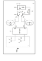
도 2는 본 발명의 제1 측면에 따른 지향성 안테나 모듈의 가능한 예시적인 실시예를 나타낸 블록도이다.
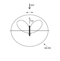
도 3은 특정 동작 모드에서 제1 측면에 따른 지향성 안테나 모듈에 의해 수행되는 최소 방향 탐지를 나타내는 개략도이다.
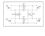
도 4는 본 발명의 제1 측면에 따른 지향성 안테나 모듈 내 180도 하이브리드의 가능한 예시적인 구현예를 나타내는 회로도이다.
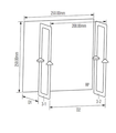
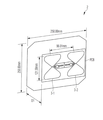
도 5는 본 발명의 제1 측면에 따른 지향성 안테나 모듈의 안테나 어레이에서 사용되는 안테나 소자의 가능한 실시예를 나타내는 개략도이다.
도 6은 본 발명의 제1 측면에 따른 지향성 안테나 모듈의 안테나 어레이에서 사용되는 안테나 소자의 다른 가능한 실시예를 나타낸다.
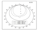
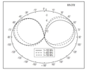
도 7a 및 도 7b는 다른 동작 모드들에서의 제1 주파수 범위에서 본 발명의 제1 측면에 따른 지향성 안태나 모듈 내 안테나 어레이에 의해 측정되는 방사 패턴들을 나타낸다.
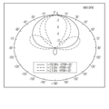
도 8a 및 도 8b는 다른 동작 모드들에서의 본 발명의 제1 측면에 따른 지향성 안테나 모듈 내 안테나 어레이에 의해 측정되는 방사 패턴들을 나타낸다.
도 9는 본 발명의 제1 측면에 따른 지향성 안테나 모듈의 가능한 다른 실시예를 개략적으로 나타내는 블록도이다.
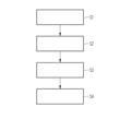
도 10은 본 발명의 제2 측면에 따른 신호원의 방향 탐지를 위한 방법의 가능한 예시적인 실시예를 나타내는 흐름도이다.
2 : 안테나 어레이
3-1, 3-2 : 안테나 소자
4 : 180도 하이브리드 회로
5-1 : 제1 출력
5-2 : 제2 출력
6-1 : 제1 신호선
6-2 : 제2 신호선
7-1 : 제1 입력
7-2 : 제2 출력
7-3 : 출력 단자
7-4 : 제어 입력
8 : 스위칭 소자
9 : 신호선
10 : 바이어스-T 커플러
11 ; 안테나 모듈 출력
12 : 제어 신호선
13 : 안테나 핸들
14 : 모듈 인식부
Claims (16)
- 지향성 안테나 모듈(1)로서,
적어도 두 개의 안테나 소자들(3)을 갖는 적어도 하나의 안테나 어레이(2)로서, 상기 안테나 소자들(3)은 상기 안테나 소자들(3)로부터 수신되는 안테나 신호의 동상 합 신호(∑) 및 이상 합 신호(Δ)를 제공하는 180도 하이브리드(4)에 연결되는, 적어도 하나의 상기 안테나 어레이(2); 및
방향 탐지 모드 제어 신호(Direction Finding Mode Control signal : DFM-CRTL)에 응답하여 상기 180도 하이브리드(4)에 의해 출력되는 상기 동상 합 신호(∑)와 상기 이상 합 신호(Δ)의 사이를 스위칭하여 상기 지향성 안테나 모듈(1)의 안테나 모듈 출력(11)에 안테나 출력 신호를 제공하는 스위칭 소자(8)를 포함하는, 지향성 안테나 모듈.
- 청구항 1에 있어서,
상기 지향성 안테나 모듈(1)은, 상기 180도 하이브리드에 의해 출력되는 상기 동상 합 신호(∑)가 상기 스위칭 소자(8)에 의해 상기 지향성 안테나 모듈(1)의 상기 안테나 모듈 출력(11)으로 스위칭되는 최대 방향 탐지 모드와, 상기 180도 하이브리드에 의해 출력되는 상기 이상 합 신호(Δ)가 상기 스위칭 소자(8)에 의해 상기 지향성 안테나 모듈(1)의 상기 안테나 모듈 출력(11)으로 스위칭되는 최소 방향 탐지 모드의 사이에서 스위칭 가능한, 지향성 안테나 모듈.
- 청구항 1 또는 2에 있어서,
상기 안테나 어레이(2)는, 반사판(RP)의 정면에 배치되는 부하 루프 안테나들(loaded loop antennas)에 의해 형성되고 제1 주파수 범위에서 사용되는 안테나 소자들(3)을 포함하는, 지향성 안테나 모듈.
- 청구항 1 내지 3 중 어느 한 항에 있어서,
상기 안테나 어레이(2)는, 반사판(RP)의 정면에 배치되는 다이폴 안테나들(dipole antennas)에 의해 형성되고 제2 주파수 범위에서 사용되는 안테나 소자들(3)을 포함하는, 지향성 안테나 모듈.
- 청구항 4에 있어서,
상기 다이폴 안테나들, 상기 180도 하이브리드(4) 및 상기 스위칭 소자(8)는, 인쇄 회로 기판(PCB)에 인쇄되는, 지향성 안테나 모듈.
- 청구항 1 내지 5 중 어느 한 항에 있어서,
상기 안테나 어레이(2)는, 제3 주파수 범위에서 사용되는 LPDA 안테나들에 의해 형성되는 안테나 소자들(3)을 포함하는, 지향성 안테나 모듈.
- 청구항 1 내지 6 중 어느 한 항에 있어서,
상기 스위칭 소자(8)는, 상기 지향성 안테나 모듈(1)의 상기 안테나 모듈 출력(11)에 배치되는 바이어스-T 소자에 의해 커플 아웃(coupled out)되는 방향 탐지 모드 제어 신호에 의해 제어되거나 또는 상기 지향성 안테나 모듈(1)의 제어 버튼에 의해 제어되는 RF 스위치인, 지향성 안테나 모듈.
- 청구항 1 내지 7 중 어느 한 항에 있어서,
상기 안테나 모듈(1)은, 상기 지향성 안테나 모듈(1)의 상기 스위칭 소자(8)로 공급되는 상기 지향성 방향 탐지 모드 제어 신호(DFM-CTRL)에 커플 인(couple in)되는 바이어스-T 소자를 포함하는 안테나 핸들(13)에 장착 가능한, 지향성 안테나 모듈.
- 청구항 8에 있어서,
상기 안테나 핸들(13)은, 상기 지향성 안테나 모듈(1)이 상기 안테나 핸들(13)에 장착된 것을 인식하는 모듈 인식부(14)를 포함하는, 지향성 안테나 모듈.
- 청구항 9에 있어서,
상기 안테나 핸들(8)의 상기 모듈 인식부(14)는, 상기 안테나 핸들(13)에 장착되는 상기 지향성 안테나 모듈(1)의 상기 적어도 하나의 안테나 어레이(2)에 구현되는 안테나 소자들의 타입 및/또는 장착되는 상기 지향성 안테나 모듈(1)의 상기 적어도 하나의 안테나 어레이(2)에서 지원되는 적어도 하나의 주파수 범위를 인식하는, 지향성 안테나 모듈.
- 청구항 1 내지 10 중 어느 한 항에 있어서,
상기 지향성 안테나 모듈(1)은,
100 MHz와 700 MHz 사이인 제1 주파수 범위에서 사용되는 반사판의 정면에 배치되는 부하 루프 안테나들에 의해 형성되는 안테나 소자들을 포함하는 제1 안테나 어레이(2-1); 및/또는
700 MHz와 2.5 GHz 사이인 제2 주파수 범위에서 사용되는 반사판의 정면에 배치되는 다이폴 안테나들에 의해 형성되는 안테나 소자들을 포함하는 제2 안테나 어레이(2-2); 및/또는
2.5 GHz를 초과하는 제3 주파수 범위에서 사용되는 LPDA 안테나들에 의해 형성되는 안테나 소자들을 포함하는 제3 안테나 어레이(2-3)를 포함하는, 지향성 안테나 모듈.
- 청구항 1 내지 11 중 어느 한 항에 있어서,
상기 지향성 안테나 모듈(1)은, 주파수 범위 선택 제어 신호(FRS-CRTL)에 응답하여 상이한 주파수 범위들의 사이에서 스위칭 가능한, 지향성 안테나 모듈.
- 청구항 11 또는 12에 있어서,
상기 지향성 안테나 모듈(1)의 안테나 어레이(2-i) 각각은, 상기 각 안테나 어레이(2-i)의 안테나 소자들(3)으로부터 수신되는 상기 안테나 신호들의 동상 합 신호(∑) 및 이상 합 신호(Δ)를 제공하는 관련되는 180도 하이브리드(4-i)에 연결되는, 지향성 안테나 모듈.
- 청구항 13에 있어서,
각 180도 하이브리드(4-i)에 연결되는 관련되는 스위칭 소자(8-i)는, 방향 탐지 모드 제어 신호(DFM-CRTL)에 응답하여 상기 각 180도 하이브리드(4-i)에 의해 출력되는 상기 동상 합 신호(∑)와 상기 이상 합 신호(Δ)의 사이에서 스위칭하도록 연결되어 상기 지향성 안테나 모듈(1)의 주파수 다중화부(12)에 인가되는 각 안테나 어레이(2-i)의 출력 신호를 출력하는, 지향성 안테나 모듈.
- 청구항 11 내지 14 중 어느 한 항에 있어서, 상기 부하 루프 안테나들과 상기 지향성 안테나 모듈(1)의 제1 안테나 어레이(2-1)에서 구현되는 상기 안테나 소자들의 상기 반사판(RP) 사이의 거리 및/또는 상기 다이폴 안테나와 상기 지향성 안테나 모듈(1)의 상기 제2 안테나 어레이(2-2)에서 구현되는 상기 안테나 소자들의 상기 반사판(RP) 사이의 거리는, 조정 가능한, 지향성 안테나 모듈.
- 신호원의 방향 탐지 방법으로서,
지향성 안테나 모듈(1)을, 상기 지향성 안테나 모듈(1) 내 안테나 어레이의 적어도 두 개의 안테나 소자들에 연결되는 180도 하이브리드에 의해 출력되는 동상 합 신호(∑)가 상기 지향성 안테나 모듈(1)에 의해 출력되는 최대 방향 탐지 모드로 스위칭하는 단계(S1);
상기 지향성 안테나 모듈(1)을, 상기 지향성 안테나 모듈(1)에 의해 출력되는 상기 동상 합 신호가 최대치에 도달할 때까지 피벗하는 단계(S2);
상기 지향성 안테나 모듈(1)을, 상기 지향성 안테나 모듈(1) 내 상기 안테나 어레이(2)의 적어도 두 개의 안테나 소자들에 연결되는 상기 180도 하이브리드에 의해 출력되는 이상 합 신호(Δ)가 상기 안테나 모듈(1)에 의해 출력되는 최소 방향 탐지 모드로 스위칭하는 단계(S3); 및
상기 지향성 안테나 모듈(1)을, 상기 지향성 안테나 모듈(1)에 의해 출력되는 상기 이상 합 신호가 신호원의 방위를 나타내는 최소치에 도달할 때까지 피벗하는 단계(S4)를 포함하는, 신호원의 방향 탐지 방법.
Applications Claiming Priority (2)
| Application Number | Priority Date | Filing Date | Title |
|---|---|---|---|
| EP16166220.0 | 2016-04-20 | ||
| EP16166220.0A EP3236278B1 (en) | 2016-04-20 | 2016-04-20 | Directional antenna module |
Publications (2)
| Publication Number | Publication Date |
|---|---|
| KR20170120032A true KR20170120032A (ko) | 2017-10-30 |
| KR102289873B1 KR102289873B1 (ko) | 2021-08-13 |
Family
ID=55794910
Family Applications (1)
| Application Number | Title | Priority Date | Filing Date |
|---|---|---|---|
| KR1020170049185A Active KR102289873B1 (ko) | 2016-04-20 | 2017-04-17 | 지향성 안테나 모듈 |
Country Status (5)
| Country | Link |
|---|---|
| US (1) | US10790584B2 (ko) |
| EP (1) | EP3236278B1 (ko) |
| KR (1) | KR102289873B1 (ko) |
| CN (1) | CN107305245B (ko) |
| ES (1) | ES2842198T3 (ko) |
Families Citing this family (7)
| Publication number | Priority date | Publication date | Assignee | Title |
|---|---|---|---|---|
| CN107959126B (zh) * | 2017-12-13 | 2024-02-27 | 华诺星空技术股份有限公司 | 一种用于反无人机被动探测及定位的天线装置 |
| CN109633722B (zh) * | 2019-01-11 | 2023-01-24 | 中国民航大学 | 基于三分之一l1波长天线构型的小型无人机卫星寻北方法 |
| CN110797660B (zh) * | 2019-11-14 | 2021-07-13 | 中信科移动通信技术股份有限公司 | 测向天线及测向方法 |
| CA3209399A1 (en) * | 2021-02-24 | 2022-09-01 | Michael Thomas Pace | System and method for a digitally beamformed phased array feed |
| US12088013B2 (en) | 2021-03-30 | 2024-09-10 | Skyworks Solutions, Inc. | Frequency range two antenna array with switches for joining antennas for frequency range one communications |
| CN113219403A (zh) * | 2021-05-20 | 2021-08-06 | 南京中原得生电子实业有限公司 | 便携式监测测向天线阵系统 |
| CN114527424B (zh) * | 2022-02-16 | 2024-12-31 | Oppo广东移动通信有限公司 | 定位方法、装置、终端配件、移动终端及电子设备 |
Citations (8)
| Publication number | Priority date | Publication date | Assignee | Title |
|---|---|---|---|---|
| US4240080A (en) * | 1979-11-19 | 1980-12-16 | The United States Of America As Represented By The Secretary Of The Army | Short backfire antenna with sum and error patterns |
| US4319249A (en) * | 1980-01-30 | 1982-03-09 | Westinghouse Electric Corp. | Method and antenna for improved sidelobe performance in dipole arrays |
| KR20010014070A (ko) * | 1998-04-22 | 2001-02-26 | 요트.게.아. 롤페즈 | 안테나 다이버시티 시스템 |
| US20070139285A1 (en) * | 2004-09-22 | 2007-06-21 | Matsushita Electric Industrial Co., Ltd. | Loop antenna unit and radio communication medium processor |
| WO2009050488A2 (en) * | 2007-10-19 | 2009-04-23 | Technology Solutions (Uk) Limited | Readers |
| JP2010223649A (ja) * | 2009-03-23 | 2010-10-07 | Furukawa Electric Co Ltd:The | レーダ装置 |
| CN203423253U (zh) * | 2013-08-27 | 2014-02-05 | 中船重工鹏力(南京)大气海洋信息系统有限公司 | 便携式高频地波雷达接收天线 |
| KR20160029616A (ko) * | 2014-09-05 | 2016-03-15 | 한국전자통신연구원 | 두 개의 베이스라인을 사용한 하이브리드 방향탐지 장치 및 방법 |
Family Cites Families (18)
| Publication number | Priority date | Publication date | Assignee | Title |
|---|---|---|---|---|
| US4360816A (en) * | 1971-07-21 | 1982-11-23 | The United States Of America As Represented By The Secretary Of The Navy | Phased array of six log-periodic dipoles |
| GB1472893A (en) * | 1974-01-30 | 1977-05-11 | Rudge A | Directional antenna systems |
| US4315266A (en) * | 1980-07-25 | 1982-02-09 | Nasa | Spiral slotted phased antenna array |
| DE9002945U1 (de) * | 1990-03-15 | 1990-09-13 | Weiner, Karl, Dipl.-Verwaltungswirt, 8670 Hof | Schmalbandiger Mono- bzw. Duobanderreger mit homogenen gleichen Öffnungswinkeln (Halbwertsbreiten) ohne statischer Aufladung für Parabolaperturen |
| DE10012080C1 (de) * | 2000-03-14 | 2001-10-31 | Daimler Chrysler Ag | Antennenarray und Verfahren zum Betrieb eines Antennenarrays |
| US6933907B2 (en) * | 2003-04-02 | 2005-08-23 | Dx Antenna Company, Limited | Variable directivity antenna and variable directivity antenna system using such antennas |
| US7505435B2 (en) * | 2003-12-02 | 2009-03-17 | Intel Corporation | RF circuitry and compact hybrid for wireless communication devices |
| KR200371277Y1 (ko) * | 2004-05-18 | 2004-12-29 | (주)더블유엘호스트 | 단일 빔 안테나를 사용한 알 에프 중계시스템 |
| JP4509870B2 (ja) * | 2005-06-09 | 2010-07-21 | Dxアンテナ株式会社 | アンテナ装置 |
| CN101436714B (zh) * | 2007-11-15 | 2012-07-11 | 大同大学 | 部分反射面天线 |
| US20090160638A1 (en) * | 2007-12-20 | 2009-06-25 | 3M Innovative Properties Company | Radio frequency identification reader system |
| RU2563455C2 (ru) * | 2009-06-08 | 2015-09-20 | Интел Корпорейшн | Многоэлементная антенная решетка с амплитудной и фазовой компенсацией с адаптивным предварительным искажением для беспроводной сети |
| US9342716B2 (en) * | 2010-02-04 | 2016-05-17 | Carefusion 303, Inc. | Software-defined multi-mode RFID read devices |
| CN201804103U (zh) * | 2010-10-12 | 2011-04-20 | 成都点阵科技有限公司 | 便携式一体化无线电监测测向主机 |
| KR20130095128A (ko) * | 2012-02-17 | 2013-08-27 | 한국전자통신연구원 | 리더 안테나 및 이를 포함하는 rfid 전자 선반 |
| US20140049443A1 (en) * | 2012-08-15 | 2014-02-20 | Daniel A. Katz | Extendable Loop Antenna for Portable Communication Device |
| CN104239834A (zh) * | 2013-06-24 | 2014-12-24 | 万信科技系统有限公司 | 无线射频识别阅读器系统及其控制方法 |
| US10289877B2 (en) * | 2013-09-23 | 2019-05-14 | Hand Held Products, Inc. | Directional antenna for RFID tag finder |
-
2016
- 2016-04-20 EP EP16166220.0A patent/EP3236278B1/en active Active
- 2016-04-20 ES ES16166220T patent/ES2842198T3/es active Active
-
2017
- 2017-03-10 US US15/456,200 patent/US10790584B2/en active Active
- 2017-04-17 KR KR1020170049185A patent/KR102289873B1/ko active Active
- 2017-04-19 CN CN201710306468.7A patent/CN107305245B/zh active Active
Patent Citations (8)
| Publication number | Priority date | Publication date | Assignee | Title |
|---|---|---|---|---|
| US4240080A (en) * | 1979-11-19 | 1980-12-16 | The United States Of America As Represented By The Secretary Of The Army | Short backfire antenna with sum and error patterns |
| US4319249A (en) * | 1980-01-30 | 1982-03-09 | Westinghouse Electric Corp. | Method and antenna for improved sidelobe performance in dipole arrays |
| KR20010014070A (ko) * | 1998-04-22 | 2001-02-26 | 요트.게.아. 롤페즈 | 안테나 다이버시티 시스템 |
| US20070139285A1 (en) * | 2004-09-22 | 2007-06-21 | Matsushita Electric Industrial Co., Ltd. | Loop antenna unit and radio communication medium processor |
| WO2009050488A2 (en) * | 2007-10-19 | 2009-04-23 | Technology Solutions (Uk) Limited | Readers |
| JP2010223649A (ja) * | 2009-03-23 | 2010-10-07 | Furukawa Electric Co Ltd:The | レーダ装置 |
| CN203423253U (zh) * | 2013-08-27 | 2014-02-05 | 中船重工鹏力(南京)大气海洋信息系统有限公司 | 便携式高频地波雷达接收天线 |
| KR20160029616A (ko) * | 2014-09-05 | 2016-03-15 | 한국전자통신연구원 | 두 개의 베이스라인을 사용한 하이브리드 방향탐지 장치 및 방법 |
Also Published As
| Publication number | Publication date |
|---|---|
| KR102289873B1 (ko) | 2021-08-13 |
| EP3236278B1 (en) | 2020-12-09 |
| CN107305245A (zh) | 2017-10-31 |
| US20170310003A1 (en) | 2017-10-26 |
| US10790584B2 (en) | 2020-09-29 |
| ES2842198T3 (es) | 2021-07-13 |
| EP3236278A1 (en) | 2017-10-25 |
| CN107305245B (zh) | 2023-12-22 |
Similar Documents
| Publication | Publication Date | Title |
|---|---|---|
| KR102289873B1 (ko) | 지향성 안테나 모듈 | |
| Zhong et al. | A compact dual-band circularly polarized antenna with wide axial-ratio beamwidth for vehicle GPS satellite navigation application | |
| US7577464B2 (en) | Compact antenna system for polarization sensitive null steering and direction-finding | |
| Gómez-Tornero et al. | Hybrid analog-digital processing system for amplitude-monopulse RSSI-based MIMO WiFi direction-of-arrival estimation | |
| US7924225B2 (en) | Direction finding antenna systems and methods for use thereof | |
| CN112103626B (zh) | 渐缩壁罩 | |
| Ghaemi et al. | A small-aperture, ultrawideband HF/VHF direction-finding system for unmanned aerial vehicles | |
| KR102080305B1 (ko) | 일체형 적층 패치 배열 안테나 | |
| US20160181690A1 (en) | Pentaband antenna | |
| EP4411986A1 (en) | Controlled radiation pattern antenna for jamming/spoofing resistant airborne gnss sensors | |
| CN111613881A (zh) | 测向接收装置及测向系统 | |
| Muqaibel et al. | Sparse DOA estimation for directional antenna arrays: An experimental validation | |
| Ma et al. | Broadband, small-aperture direction-finding array with azimuth and elevation estimation capability | |
| CN113109757A (zh) | 一种基于干涉仪的测向微波信道组件 | |
| WO2010006484A1 (en) | Direction finding antenna systems and methods for use thereof | |
| Vasanelli et al. | Characterization of mm-Wave Conformal Antenna Arrays for a $3\times 8$ MIMO Radar | |
| Toprak et al. | A compact wideband circular polarized antenna for automotive gnss applications | |
| Hua et al. | Direction-of-arrival estimator using array switching on software defined radio platform | |
| Alsliety et al. | A study of ground-plane-level and vehicle-level radiation patterns of GPS antenna in telematics applications | |
| US12009915B2 (en) | Compact receiver system with antijam and antispoof capability | |
| KR100822705B1 (ko) | 위상비교 방식의 방향 탐지 안테나 | |
| CN215449570U (zh) | 一种基于干涉仪的测向微波信道组件 | |
| Tyrväinen | Design of a Vivaldi Antenna Array for Direction Finding Applications | |
| Baharuddin et al. | An Electronically Steerable Antenna Designed for Accurate DoA Determination of U-NII-2-Extended WLAN Devices | |
| Ma | Wideband, Direction of Arrival Estimation Using Small-Aperture Antenna Arrays |
Legal Events
| Date | Code | Title | Description |
|---|---|---|---|
| PA0109 | Patent application |
St.27 status event code: A-0-1-A10-A12-nap-PA0109 |
|
| PG1501 | Laying open of application |
St.27 status event code: A-1-1-Q10-Q12-nap-PG1501 |
|
| A201 | Request for examination | ||
| PA0201 | Request for examination |
St.27 status event code: A-1-2-D10-D11-exm-PA0201 |
|
| D13-X000 | Search requested |
St.27 status event code: A-1-2-D10-D13-srh-X000 |
|
| D14-X000 | Search report completed |
St.27 status event code: A-1-2-D10-D14-srh-X000 |
|
| E902 | Notification of reason for refusal | ||
| PE0902 | Notice of grounds for rejection |
St.27 status event code: A-1-2-D10-D21-exm-PE0902 |
|
| E13-X000 | Pre-grant limitation requested |
St.27 status event code: A-2-3-E10-E13-lim-X000 |
|
| P11-X000 | Amendment of application requested |
St.27 status event code: A-2-2-P10-P11-nap-X000 |
|
| P13-X000 | Application amended |
St.27 status event code: A-2-2-P10-P13-nap-X000 |
|
| E701 | Decision to grant or registration of patent right | ||
| PE0701 | Decision of registration |
St.27 status event code: A-1-2-D10-D22-exm-PE0701 |
|
| GRNT | Written decision to grant | ||
| PR0701 | Registration of establishment |
St.27 status event code: A-2-4-F10-F11-exm-PR0701 |
|
| PR1002 | Payment of registration fee |
St.27 status event code: A-2-2-U10-U11-oth-PR1002 Fee payment year number: 1 |
|
| PG1601 | Publication of registration |
St.27 status event code: A-4-4-Q10-Q13-nap-PG1601 |
|
| PR1001 | Payment of annual fee |
St.27 status event code: A-4-4-U10-U11-oth-PR1001 Fee payment year number: 4 |
|
| PR1001 | Payment of annual fee |
St.27 status event code: A-4-4-U10-U11-oth-PR1001 Fee payment year number: 5 |
|
| U11 | Full renewal or maintenance fee paid |
Free format text: ST27 STATUS EVENT CODE: A-4-4-U10-U11-OTH-PR1001 (AS PROVIDED BY THE NATIONAL OFFICE) Year of fee payment: 5 |