KR20170125745A - 팬텀 전압 검출기가 있는 정전 감지 시스템 - Google Patents
팬텀 전압 검출기가 있는 정전 감지 시스템 Download PDFInfo
- Publication number
- KR20170125745A KR20170125745A KR1020170056931A KR20170056931A KR20170125745A KR 20170125745 A KR20170125745 A KR 20170125745A KR 1020170056931 A KR1020170056931 A KR 1020170056931A KR 20170056931 A KR20170056931 A KR 20170056931A KR 20170125745 A KR20170125745 A KR 20170125745A
- Authority
- KR
- South Korea
- Prior art keywords
- power source
- voltage
- rectifier
- phantom
- switch
- Prior art date
- Legal status (The legal status is an assumption and is not a legal conclusion. Google has not performed a legal analysis and makes no representation as to the accuracy of the status listed.)
- Granted
Links
Images


Classifications
-
- G—PHYSICS
- G01—MEASURING; TESTING
- G01R—MEASURING ELECTRIC VARIABLES; MEASURING MAGNETIC VARIABLES
- G01R31/00—Arrangements for testing electric properties; Arrangements for locating electric faults; Arrangements for electrical testing characterised by what is being tested not provided for elsewhere
- G01R31/40—Testing power supplies
- G01R31/42—AC power supplies
-
- H—ELECTRICITY
- H02—GENERATION; CONVERSION OR DISTRIBUTION OF ELECTRIC POWER
- H02J—ELECTRIC POWER NETWORKS; CIRCUIT ARRANGEMENTS OR SYSTEMS FOR SUPPLYING OR DISTRIBUTING ELECTRIC POWER; SYSTEMS FOR STORING ELECTRIC ENERGY
- H02J9/00—Circuit arrangements for emergency or stand-by power supply, e.g. for emergency lighting
- H02J9/04—Circuit arrangements for emergency or stand-by power supply, e.g. for emergency lighting in which the distribution system is disconnected from the normal source and connected to a standby source
- H02J9/06—Circuit arrangements for emergency or stand-by power supply, e.g. for emergency lighting in which the distribution system is disconnected from the normal source and connected to a standby source with automatic change-over, e.g. UPS systems
- H02J9/061—Circuit arrangements for emergency or stand-by power supply, e.g. for emergency lighting in which the distribution system is disconnected from the normal source and connected to a standby source with automatic change-over, e.g. UPS systems for DC powered loads
-
- G—PHYSICS
- G01—MEASURING; TESTING
- G01R—MEASURING ELECTRIC VARIABLES; MEASURING MAGNETIC VARIABLES
- G01R1/00—Details of instruments or arrangements of the types included in groups G01R5/00 - G01R13/00 and G01R31/00
- G01R1/30—Structural combination of electric measuring instruments with basic electronic circuits, e.g. with amplifier
-
- G—PHYSICS
- G01—MEASURING; TESTING
- G01R—MEASURING ELECTRIC VARIABLES; MEASURING MAGNETIC VARIABLES
- G01R19/00—Arrangements for measuring currents or voltages or for indicating presence or sign thereof
- G01R19/145—Indicating the presence of current or voltage
- G01R19/155—Indicating the presence of voltage
-
- G—PHYSICS
- G01—MEASURING; TESTING
- G01R—MEASURING ELECTRIC VARIABLES; MEASURING MAGNETIC VARIABLES
- G01R21/00—Arrangements for measuring electric power or power factor
- G01R21/001—Measuring real or reactive component; Measuring apparent energy
- G01R21/003—Measuring reactive component
Landscapes
- Physics & Mathematics (AREA)
- General Physics & Mathematics (AREA)
- Engineering & Computer Science (AREA)
- Power Engineering (AREA)
- Business, Economics & Management (AREA)
- Emergency Management (AREA)
- Measurement Of Current Or Voltage (AREA)
Abstract
Description
도 1 은 일 실시예에 따르는 예시적인 정전 감지 시스템의 블록도를 도시한다;
도 2 는 일 실시예에 따르는, 이차 전력원을 포함하는 예시적인 정전 감지 시스템을 도시한다;
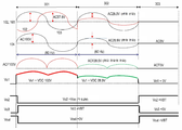
도 3 은 일 실시예에 따르는 예시적인 정전 감지 시스템에 대한 타이밍 도이다;
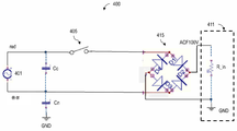
도 4 는 일 실시예에 따르는 예시적인 정전 감지 시스템의 블록도를 도시한다;
도 5 는 일 실시예에 따르는, 이차 전력원을 포함하는 예시적인 정전 감지 시스템을 도시한다;
도 6 은 일 실시예에 따르는 정전 감지 시스템에 대한 예시적인 타이밍 도를 도시한다;
도 7 은 일 실시예에 따르는 감지 증폭기를 포함하는 예시적인 정전 감지 시스템을 도시한다;
도 8 은 일 실시예에 따르는 정전 감지 시스템에 대한 예시적인 타이밍 도를 도시한다; 그리고
도 9 는 일 실시예에 따르는 정전 감지 시스템을 포함하는 예시적인 시스템을 도시한다.
도면은 반드시 척도에 맞게 도시되는 것은 아니고, 도면 전체에 걸쳐서 예시를 위해 유사한 구조 또는 기능의 요소들은 일반적으로 유사한 참조 번호에 의해 표현된다. 도면들은 본 명세서에서 설명되는 다양한 실시예들을 쉽게 설명하기 위한 것일 뿐이다. 도면은 본 명세서에 개시된 교시내용의 모든 양태를 기술하지 않으며, 청구항의 범위를 한정하지 않는다.
Claims (20)
- 정전 감지 시스템으로서,
3상선 및 중성선을 사용하여 교류(AC) 전력을 제공하는 일차 전력원;
이차 전력원;
하나 이상의 감지 소자를 포함하는 감지 블록; 및
상기 일차 전력원으로부터의 AC 전력을 정류하도록 구성되고, 정류된 전력을 감지 블록 전압 검출기로 제공하는 정류기를 포함하고,
상기 일차 전력원의 상기 3상선 중 두 개의 선과 중성선은 상기 정류기에 연결되며, 상기 두 개의 선 중 제 1 선은 스위치를 통해 상기 정류기에 연결되고, 상기 두 개의 선 중 제 2 선은 상기 정류기에 직접적으로 연결되며,
상기 감지 블록은 팬텀 전압(phantom voltage)을 감지하고, 정전 기간 동안 상기 이차 전력원에 대응하는 출력 신호를 제공하는, 정전 감지 시스템. - 제 1 항에 있어서,
상기 출력 신호는 스위치-온 기간과 스위치-오프 기간 동안 상기 일차 전력원에 대응하는, 정전 감지 시스템. - 제 1 항에 있어서,
상기 하나 이상의 감지 소자는 저항 및 커패시터를 포함하는, 정전 감지 시스템. - 제 3 항에 있어서,
상기 팬텀 전압은 상기 저항 및 커패시터에 의해 직류(DC) 레벨로 변환되는, 정전 감지 시스템. - 제 4 항에 있어서,
상기 감지 블록은, 상기 DC 레벨이 제 1 트랜지스터의 베이스-이미터 전압보다 더 높은 경우 상기 팬텀 전압 및 전류를 증폭하는 제 1 트랜지스터를 더 포함하는, 정전 감지 시스템. - 제 5 항에 있어서,
상기 감지 블록은, 상기 팬텀 전압을 중간 전압으로 변환하고 상기 출력 신호를 제공하는 제 2 트랜지스터 및 인버터를 더 포함하는, 정전 감지 시스템. - 제 1 항에 있어서,
상기 제 1 선은 흑색선이고 상기 제 2 선은 적색선인, 정전 감지 시스템. - 제 1 항에 있어서,
상기 제 1 선은 적색선이고 상기 제 2 선은 중성선인, 정전 감지 시스템. - 제 1 항에 있어서,
상기 감지 블록은, 상기 하나 이상의 감지 소자에 커플링되는 감지 증폭기 및 상기 감지 증폭기와 직렬 연결되는 드라이버를 더 포함하는, 정전 감지 시스템. - 제 9 항에 있어서,
상기 감지 증폭기는 레퍼런스 전압에 기초하여 상기 팬텀 전압을 증폭하는, 정전 감지 시스템. - 제 1 항에 있어서,
상기 정전 감지 시스템은 AC/DC 컨버터를 더 포함하고,
상기 감지 블록은 상기 AC/DC 컨버터로부터 수신되는 신호에 기초하여 상기 이차 전력원에 대응하는 출력 전압을 제공하는, 정전 감지 시스템. - 제 1 항에 있어서,
상기 이차 전력원에 대응하는 출력 신호는 정전 기간 동안 디바이스로 제공되는, 정전 감지 시스템. - 제 1 항에 있어서,
상기 감지 블록은 디바이스 내에 통합되는, 정전 감지 시스템. - 제 1 항에 있어서,
디바이스는 응급 라이트, 고-정밀도 머신, 및 의료 디바이스 중 하나인, 정전 감지 시스템. - 정류기에 커플링된 하나 이상의 감지 소자를 포함하는 팬텀 전압 검출기로서,
상기 정류기는 일차 전력원으로부터의 AC 전력을 정류하도록 구성되고,
상기 일차 전력원의 3상선 중 두 개의 선과 중성선은 상기 정류기에 연결되며,
상기 두 개의 선 중 제 1 선은 스위치를 통해 상기 정류기에 연결되고,
상기 두 개의 선 중 제 2 선은 상기 정류기에 직접적으로 연결되며,
상기 하나 이상의 감지 소자는 팬텀 전압을 검출하고,
상기 팬텀 전압 검출기는 정전 기간 동안 이차 전력원에 대응하는 출력 신호를 제공하는, 팬텀 전압 검출기. - 제 15 항에 있어서,
상기 출력 신호는 스위치-온 기간과 스위치-오프 기간 동안 상기 일차 전력원에 대응하는, 팬텀 전압 검출기. - 제 15 항에 있어서,
상기 하나 이상의 감지 소자는 저항 및 커패시터를 포함하는, 팬텀 전압 검출기. - 제 17 항에 있어서,
상기 감지 블록은 상기 팬텀 전압을 출력 신호로 변환하는 하나 이상의 트랜지스터 및 인버터를 더 포함하는, 팬텀 전압 검출기. - 제 15 항에 있어서,
상기 팬텀 전압 검출기는, 상기 하나 이상의 감지 소자에 커플링되는 감지 증폭기 및 상기 감지 증폭기와 직렬 연결되는 드라이버를 더 포함하는, 팬텀 전압 검출기. - 제 19 항에 있어서,
상기 감지 증폭기는 레퍼런스 전압에 기초하여 상기 팬텀 전압을 증폭하는, 팬텀 전압 검출기.
Applications Claiming Priority (4)
| Application Number | Priority Date | Filing Date | Title |
|---|---|---|---|
| US201662332421P | 2016-05-05 | 2016-05-05 | |
| US62/332,421 | 2016-05-05 | ||
| US201662359538P | 2016-07-07 | 2016-07-07 | |
| US62/359,538 | 2016-07-07 |
Publications (2)
| Publication Number | Publication Date |
|---|---|
| KR20170125745A true KR20170125745A (ko) | 2017-11-15 |
| KR102170996B1 KR102170996B1 (ko) | 2020-10-28 |
Family
ID=60244050
Family Applications (1)
| Application Number | Title | Priority Date | Filing Date |
|---|---|---|---|
| KR1020170056931A Active KR102170996B1 (ko) | 2016-05-05 | 2017-05-04 | 팬텀 전압 검출기가 있는 정전 감지 시스템 |
Country Status (2)
| Country | Link |
|---|---|
| US (1) | US10454299B2 (ko) |
| KR (1) | KR102170996B1 (ko) |
Cited By (1)
| Publication number | Priority date | Publication date | Assignee | Title |
|---|---|---|---|---|
| KR20190105523A (ko) * | 2018-03-05 | 2019-09-17 | 권익수 | 결합된 인덕터 장치를 포함하는 팬텀 전압 검출기를 구비한 정전 감지 시스템 |
Families Citing this family (2)
| Publication number | Priority date | Publication date | Assignee | Title |
|---|---|---|---|---|
| CN110401198B (zh) * | 2019-07-29 | 2021-02-09 | 陕西惠齐电力科技开发有限公司 | 一种铁路车站低压变配电智能监控系统 |
| EP3787375B1 (en) * | 2019-08-30 | 2024-10-02 | Tridonic GmbH & Co. KG | Adapter for electrically connecting a lighting device to an electrical track |
Citations (4)
| Publication number | Priority date | Publication date | Assignee | Title |
|---|---|---|---|---|
| JP2000341443A (ja) * | 1999-05-31 | 2000-12-08 | Sharp Corp | Isdnにおける電力供給装置 |
| KR20110002773U (ko) * | 2009-09-11 | 2011-03-17 | 미시린 프라스페리티 컴퍼니 리미티드 | 전력 관리 장치 |
| KR20130090598A (ko) * | 2012-02-06 | 2013-08-14 | 박성훈 | 엘이디 조명의 충전시스템 및 정전감지 장치 |
| US20150194843A1 (en) * | 2014-01-03 | 2015-07-09 | Capstone Lighting Technologies, LLC | Apparatus and method for switch state detection and controlling electrical power |
Family Cites Families (11)
| Publication number | Priority date | Publication date | Assignee | Title |
|---|---|---|---|---|
| US3976986A (en) * | 1973-09-27 | 1976-08-24 | Zabroski Stanley E | Emergency lamp and solid state switching circuit therefor |
| US4323820A (en) * | 1980-03-27 | 1982-04-06 | Foxmar Industries Inc. | Emergency lighting system |
| US5148158A (en) * | 1988-03-24 | 1992-09-15 | Teledyne Industries, Inc. | Emergency lighting unit having remote test capability |
| US8299712B2 (en) * | 2007-04-06 | 2012-10-30 | Sunovia Energy Technologies, Inc. | Light unit with internal power failure detection |
| CN102265481A (zh) * | 2008-12-08 | 2011-11-30 | Tycka设计私人有限公司 | 一种改进的安全系统 |
| US8132933B2 (en) * | 2010-08-11 | 2012-03-13 | Albert Chao | Power blackout bulb |
| GB2513221B (en) * | 2011-03-31 | 2015-07-29 | Litonics Ltd | Lighting device |
| JP2014002904A (ja) * | 2012-06-18 | 2014-01-09 | Cyber Coin Kk | 蛍光灯型led照明装置およびその点消灯モード切替方法 |
| KR101667135B1 (ko) * | 2015-01-15 | 2016-10-17 | 권익수 | 비상등 기능을 가지는 전등 장치 |
| US9811985B2 (en) * | 2015-05-04 | 2017-11-07 | Ledsens Llc | Power outage safety light bulb |
| ITUB20155559A1 (it) * | 2015-11-13 | 2017-05-13 | Beghelli Spa | Alimentatore di emergenza per apparecchi di illuminazione |
-
2017
- 2017-05-04 KR KR1020170056931A patent/KR102170996B1/ko active Active
- 2017-05-04 US US15/587,147 patent/US10454299B2/en active Active - Reinstated
Patent Citations (4)
| Publication number | Priority date | Publication date | Assignee | Title |
|---|---|---|---|---|
| JP2000341443A (ja) * | 1999-05-31 | 2000-12-08 | Sharp Corp | Isdnにおける電力供給装置 |
| KR20110002773U (ko) * | 2009-09-11 | 2011-03-17 | 미시린 프라스페리티 컴퍼니 리미티드 | 전력 관리 장치 |
| KR20130090598A (ko) * | 2012-02-06 | 2013-08-14 | 박성훈 | 엘이디 조명의 충전시스템 및 정전감지 장치 |
| US20150194843A1 (en) * | 2014-01-03 | 2015-07-09 | Capstone Lighting Technologies, LLC | Apparatus and method for switch state detection and controlling electrical power |
Cited By (1)
| Publication number | Priority date | Publication date | Assignee | Title |
|---|---|---|---|---|
| KR20190105523A (ko) * | 2018-03-05 | 2019-09-17 | 권익수 | 결합된 인덕터 장치를 포함하는 팬텀 전압 검출기를 구비한 정전 감지 시스템 |
Also Published As
| Publication number | Publication date |
|---|---|
| US20170324272A1 (en) | 2017-11-09 |
| US10454299B2 (en) | 2019-10-22 |
| KR102170996B1 (ko) | 2020-10-28 |
Similar Documents
| Publication | Publication Date | Title |
|---|---|---|
| CN101930026B (zh) | 一种具有功率损耗检测功能的电子装置 | |
| US9740262B2 (en) | Power supply detecting circuit | |
| US9651588B2 (en) | Power detecting circuit | |
| KR102170996B1 (ko) | 팬텀 전압 검출기가 있는 정전 감지 시스템 | |
| US9557353B2 (en) | Power supply detecting circuit | |
| US20120101750A1 (en) | Device for measuring power supply efficiency and method for using same | |
| KR102170709B1 (ko) | 결합된 인덕터 장치를 포함하는 팬텀 전압 검출기를 구비한 정전 감지 시스템 | |
| US8391034B2 (en) | Power supply module with filtering circuit and power supply module assembly | |
| US20080024138A1 (en) | Identifying apparatus for ac power supply arrangement | |
| US7982626B2 (en) | Proper grounding detection and alarm circuit for electronic device | |
| US7830102B2 (en) | Light source driving device | |
| US20120187866A1 (en) | Multi-lamp driving system | |
| US5814977A (en) | Power supply for compensating a failed voltage | |
| US20190097415A1 (en) | Devices and methods for fault indication connector circuits | |
| US20220373581A1 (en) | Method and Circuit Arrangement for Ascertaining a Type and Value of an Input Voltage | |
| TWM534700U (zh) | 具電源反接保護與偵測機制的車用電器裝置 | |
| US12047046B2 (en) | System and method for auto calibration in a power blackout sensing system | |
| US20050229015A1 (en) | Method for controlling the mode of an electronic application | |
| JPH06113553A (ja) | Acアダプタ | |
| US6690151B2 (en) | Phase detection circuit | |
| JP5074087B2 (ja) | 放電ランプ駆動装置 | |
| US20240230728A9 (en) | Abnormal detection circuit for detecting three-phase ac power | |
| CN106483396A (zh) | 一种负载供电电源的识别系统及方法 | |
| JP2007185088A (ja) | 電圧検知回路及び該電圧検知回路を用いる放電ランプ駆動システム | |
| JP2005300284A (ja) | アナログ入力回路の電源電圧低下検出回路 |
Legal Events
| Date | Code | Title | Description |
|---|---|---|---|
| PA0109 | Patent application |
Patent event code: PA01091R01D Comment text: Patent Application Patent event date: 20170504 |
|
| PG1501 | Laying open of application | ||
| A201 | Request for examination | ||
| PA0201 | Request for examination |
Patent event code: PA02012R01D Patent event date: 20190319 Comment text: Request for Examination of Application Patent event code: PA02011R01I Patent event date: 20170504 Comment text: Patent Application |
|
| E902 | Notification of reason for refusal | ||
| PE0902 | Notice of grounds for rejection |
Comment text: Notification of reason for refusal Patent event date: 20200225 Patent event code: PE09021S01D |
|
| E701 | Decision to grant or registration of patent right | ||
| PE0701 | Decision of registration |
Patent event code: PE07011S01D Comment text: Decision to Grant Registration Patent event date: 20201019 |
|
| GRNT | Written decision to grant | ||
| PR0701 | Registration of establishment |
Comment text: Registration of Establishment Patent event date: 20201022 Patent event code: PR07011E01D |
|
| PR1002 | Payment of registration fee |
Payment date: 20201022 End annual number: 3 Start annual number: 1 |
|
| PG1601 | Publication of registration | ||
| PR1001 | Payment of annual fee |
Payment date: 20230710 Start annual number: 4 End annual number: 4 |