KR20170143324A - 절연형 다출력 전력공급장치 및 이를 갖는 전동기 구동 장치 - Google Patents
절연형 다출력 전력공급장치 및 이를 갖는 전동기 구동 장치 Download PDFInfo
- Publication number
- KR20170143324A KR20170143324A KR1020160077412A KR20160077412A KR20170143324A KR 20170143324 A KR20170143324 A KR 20170143324A KR 1020160077412 A KR1020160077412 A KR 1020160077412A KR 20160077412 A KR20160077412 A KR 20160077412A KR 20170143324 A KR20170143324 A KR 20170143324A
- Authority
- KR
- South Korea
- Prior art keywords
- power
- output
- unit
- auxiliary
- transformer
- Prior art date
- Legal status (The legal status is an assumption and is not a legal conclusion. Google has not performed a legal analysis and makes no representation as to the accuracy of the status listed.)
- Granted
Links
Images



Classifications
-
- H—ELECTRICITY
- H02—GENERATION; CONVERSION OR DISTRIBUTION OF ELECTRIC POWER
- H02M—APPARATUS FOR CONVERSION BETWEEN AC AND AC, BETWEEN AC AND DC, OR BETWEEN DC AND DC, AND FOR USE WITH MAINS OR SIMILAR POWER SUPPLY SYSTEMS; CONVERSION OF DC OR AC INPUT POWER INTO SURGE OUTPUT POWER; CONTROL OR REGULATION THEREOF
- H02M3/00—Conversion of DC power input into DC power output
- H02M3/22—Conversion of DC power input into DC power output with intermediate conversion into AC
- H02M3/24—Conversion of DC power input into DC power output with intermediate conversion into AC by static converters
- H02M3/28—Conversion of DC power input into DC power output with intermediate conversion into AC by static converters using discharge tubes with control electrode or semiconductor devices with control electrode to produce the intermediate AC
- H02M3/325—Conversion of DC power input into DC power output with intermediate conversion into AC by static converters using discharge tubes with control electrode or semiconductor devices with control electrode to produce the intermediate AC using devices of a triode or a transistor type requiring continuous application of a control signal
- H02M3/335—Conversion of DC power input into DC power output with intermediate conversion into AC by static converters using discharge tubes with control electrode or semiconductor devices with control electrode to produce the intermediate AC using devices of a triode or a transistor type requiring continuous application of a control signal using semiconductor devices only
- H02M3/33569—Conversion of DC power input into DC power output with intermediate conversion into AC by static converters using discharge tubes with control electrode or semiconductor devices with control electrode to produce the intermediate AC using devices of a triode or a transistor type requiring continuous application of a control signal using semiconductor devices only having several active switching elements
- H02M3/33576—Conversion of DC power input into DC power output with intermediate conversion into AC by static converters using discharge tubes with control electrode or semiconductor devices with control electrode to produce the intermediate AC using devices of a triode or a transistor type requiring continuous application of a control signal using semiconductor devices only having several active switching elements having at least one active switching element at the secondary side of an isolation transformer
-
- H—ELECTRICITY
- H02—GENERATION; CONVERSION OR DISTRIBUTION OF ELECTRIC POWER
- H02P—CONTROL OR REGULATION OF ELECTRIC MOTORS, ELECTRIC GENERATORS OR DYNAMO-ELECTRIC CONVERTERS; CONTROLLING TRANSFORMERS, REACTORS OR CHOKE COILS
- H02P27/00—Arrangements or methods for the control of AC motors characterised by the kind of supply voltage
- H02P27/04—Arrangements or methods for the control of AC motors characterised by the kind of supply voltage using variable-frequency supply voltage, e.g. inverter or converter supply voltage
- H02P27/06—Arrangements or methods for the control of AC motors characterised by the kind of supply voltage using variable-frequency supply voltage, e.g. inverter or converter supply voltage using DC to AC converters or inverters
Landscapes
- Engineering & Computer Science (AREA)
- Power Engineering (AREA)
- Inverter Devices (AREA)
Abstract
Description
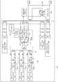
도 2는 본 발명의 다른 일 실시예에 따른 절연형 다출력 전력 공급 장치의 개략적인 구성도이다.
도 3은 본 발명의 또 다른 일 실시예에 따른 절연형 다출력 전력 공급 장치의 개략적인 구성도이다.
110: 정류부
120: 인버터부
130: 메인 제어부
140,240,340: 절연형 다출력 전력 공급 장치
141,241,341: 메인 변환부
142,242,342: 보조 변환부
143: 제어부
144,244,344: 배전압부
Claims (19)
- 입력 전력을 스위칭하는 메인 변환부;
스위칭된 입력 전력을 변압하여 복수의 제1 전력을 출력하는 제1 절연형 트랜스포머;
상기 제1 절연형 트랜스포머의 복수의 제1 전력 중 적어도 하나의 제1 전력을 스위칭하는 보조 변환부;
상기 보조 변환부에 의해 스위칭된 제1 전력을 변압하여 제2 전력을 출력하는 제2 절연형 트랜스포머; 및
상기 제2 절연형 트랜스포머로부터의 제2 전력의 전압 레벨을 체배하여 출력하는 배전압부
를 포함하는 절연형 다출력 전력 공급 장치.
- 제1항에 있어서,
상기 메인 변환부는
상기 입력 전력을 PWM(Pulse Width Modulation) 스위칭하는 메인 스위치부; 및
상기 메인 스위치부의 PWM 스위칭을 제어하는 메인 PWM 제어부
를 포함하는 절연형 다출력 전력 공급 장치.
- 제2항에 있어서,
상기 메인 변환부는 플라이백(fly-back) 컨버터인 절연형 다출력 전력 공급 장치.
- 제1항에 있어서,
상기 보조 변환부는
상기 적어도 하나의 제1 전력을 PWM 스위칭하는 보조 스위치부; 및
상기 보조 스위치부의 PWM 스위칭을 제어하는 보조 PWM 제어부
를 포함하는 절연형 다출력 전력 공급 장치.
- 제4항에 있어서,
상기 보조 스위치부는 하프 브리지(half-bridge) 스위치, 풀 브리지(full-bridge) 스위치 또는 푸쉬-풀(push-pull) 스위치 중 하나인 절연형 다출력 전력 공급 장치.
- 제1항에 있어서,
상기 복수의 제1 전력 중 적어도 일부의 제1 전력의 전압 레벨은 서로 상이한 절연형 다출력 전력 공급 장치.
- 제1항에 있어서,
상기 배전압부는 상기 제2 전력의 전압 레벨을 체배한 제1 출력 전력 및 상기 제2 전력의 극성을 마이너스로 변환한 제2 출력 전력을 출력하는 절연형 다출력 전력 공급 장치.
- 제7항에 있어서,
상기 제2 절연형 트랜스포머는 복수의 제2 전력을 출력하는 복수의 2차 권선을 포함하고,
상기 배전압부는 복수의 제1 출력 전력 및 복수의 제2 출력 전력을 출력하는 절연형 다출력 전력 공급 장치.
- 제7항에 있어서,
상기 보조 변환부는 복수개 구비되고,
상기 제2 절연형 트랜스포머는 상기 복수개의 보조 변환부에 대응되어 복수개 구비되며,
상기 배전압부는 복수개 구비되어, 상기 복수개의 배전압부는 상기 복수개의 제2 절연형 트랜스포머 각각의 제2 전력의 전압 레벨을 체배한 제1 출력 전력 및 상기 제2 전력의 극성을 마이너스로 변환한 제2 출력 전력을 출력하는 절연형 다출력 전력 공급 장치.
- 계통 전원을 정류하는 정류부;
정류된 계통 전원을 인버팅하여 전동기를 구동시키는 인버터부;
상기 인버터부의 인버팅 동작을 제어하는 메인 제어부; 및
상기 정류부, 상기 인버터부 및 상기 제어부 각각에 전력을 공급하는 절연형 다출력 전력 공급 장치를 포함하고,
상기 절연형 다출력 전력 공급 장치는 상기 정류부 및 상기 제어부에 공급되는 전력을 출력하는 제1 절연형 트랜스포머와 상기 인버터부에 공급되는 전력을 출력하는 제2 절연형 트랜스포머를 갖는 전동기 구동 장치.
- 제10항에 있어서,
상기 절연형 다출력 전력 공급 장치는
정류된 계통 전력을 스위칭하는 메인 변환부;
상기 제1 절연형 트랜스포머의 복수의 제1 전력 중 적어도 하나의 제1 전력을 스위칭하는 보조 변환부; 및
상기 제2 절연형 트랜스포머로부터의 제2 전력의 전압 레벨을 체배하여 출력하는 배전압부를 더 포함하고,
상기 제1 절연형 트랜스포머는 상기 메인 변환부에 의해 스위칭된 전력을 변압하여 상기 복수의 제1 전력을 출력하고,
상기 제2 절연형 트랜스포머는 상기 보조 변환부에 의해 스위칭된 제1 전력을 변압하여 상기 제2 전력을 출력하는 전동기 구동 장치.
- 제11항에 있어서,
상기 메인 변환부는
상기 입력 전력을 PWM(Pulse Width Modulation) 스위칭하는 메인 스위치부; 및
상기 메인 스위치부의 PWM 스위칭을 제어하는 메인 PWM 제어부
를 포함하는 전동기 구동 장치.
- 제12항에 있어서,
상기 메인 변환부는 플라이백(fly-back) 컨버터인 전동기 구동 장치.
- 제11항에 있어서,
상기 보조 변환부는
상기 적어도 하나의 제1 전력을 PWM 스위칭하는 보조 스위치부; 및
상기 보조 스위치부의 PWM 스위칭을 제어하는 보조 PWM 제어부
를 포함하는 전동기 구동 장치.
- 제14항에 있어서,
상기 보조 스위치부는 하프 브리지(half-bridge) 스위치, 풀 브리지(full-bridge) 스위치 또는 푸쉬-풀(push-pull) 스위치 중 하나인 전동기 구동 장치.
- 제11항에 있어서,
상기 복수의 제1 전력 중 적어도 일부의 제1 전력의 전압 레벨은 서로 상이한 전동기 구동 장치.
- 제11항에 있어서,
상기 배전압부는 상기 제2 전력의 전압 레벨을 체배한 제1 출력 전력 및 상기 제2 전력의 극성을 마이너스로 변환한 제2 출력 전력을 출력하는 절연형 다출력 전력 공급 장치.
- 제17항에 있어서,
상기 제2 절연형 트랜스포머는 복수의 제2 전력을 출력하는 복수의 2차 권선을 포함하고,
상기 배전압부는 복수의 제1 출력 전력 및 복수의 제2 출력 전력을 출력하는 전동기 구동 장치.
- 제17항에 있어서,
상기 보조 변환부는 복수개 구비되고,
상기 제2 절연형 트랜스포머는 상기 복수개의 보조 변환부에 대응되어 복수개 구비되며,
상기 배전압부는 복수개 구비되어, 상기 복수개의 배전압부는 상기 복수개의 제2 절연형 트랜스포머 각각의 제2 전력의 전압 레벨을 체배한 제1 출력 전력 및 상기 제2 전력의 극성을 마이너스로 변환한 제2 출력 전력을 출력하는 전동기 구동 장치.
Priority Applications (1)
| Application Number | Priority Date | Filing Date | Title |
|---|---|---|---|
| KR1020160077412A KR102165635B1 (ko) | 2016-06-21 | 2016-06-21 | 절연형 다출력 전력공급장치 및 이를 갖는 전동기 구동 장치 |
Applications Claiming Priority (1)
| Application Number | Priority Date | Filing Date | Title |
|---|---|---|---|
| KR1020160077412A KR102165635B1 (ko) | 2016-06-21 | 2016-06-21 | 절연형 다출력 전력공급장치 및 이를 갖는 전동기 구동 장치 |
Publications (2)
| Publication Number | Publication Date |
|---|---|
| KR20170143324A true KR20170143324A (ko) | 2017-12-29 |
| KR102165635B1 KR102165635B1 (ko) | 2020-10-14 |
Family
ID=60938967
Family Applications (1)
| Application Number | Title | Priority Date | Filing Date |
|---|---|---|---|
| KR1020160077412A Active KR102165635B1 (ko) | 2016-06-21 | 2016-06-21 | 절연형 다출력 전력공급장치 및 이를 갖는 전동기 구동 장치 |
Country Status (1)
| Country | Link |
|---|---|
| KR (1) | KR102165635B1 (ko) |
Cited By (2)
| Publication number | Priority date | Publication date | Assignee | Title |
|---|---|---|---|---|
| WO2023278237A1 (en) * | 2021-06-30 | 2023-01-05 | Enphase Energy, Inc. | Driver for bidirectional fet pair |
| WO2023279747A1 (zh) * | 2021-07-06 | 2023-01-12 | 中山大洋电机股份有限公司 | 一种电机控制器及应用其的电机 |
Citations (5)
| Publication number | Priority date | Publication date | Assignee | Title |
|---|---|---|---|---|
| KR960032858A (ko) * | 1995-02-01 | 1996-09-17 | 무라따 야스따까 | 디씨-디씨 컨버터(DC-DC converter) |
| US20070030716A1 (en) * | 2005-08-03 | 2007-02-08 | Mihai-Costin Manolescu | Multiple output power supply that configures itself to multiple loads |
| KR20140124485A (ko) * | 2013-04-17 | 2014-10-27 | 김득수 | 에너지저장시스템의 제어전원회로 |
| KR20160017720A (ko) | 2014-08-01 | 2016-02-17 | 현대중공업 주식회사 | 발진회로 및 그를 이용한 전원장치 |
| JP2016086562A (ja) * | 2014-10-27 | 2016-05-19 | パナソニックIpマネジメント株式会社 | 電源回路 |
-
2016
- 2016-06-21 KR KR1020160077412A patent/KR102165635B1/ko active Active
Patent Citations (5)
| Publication number | Priority date | Publication date | Assignee | Title |
|---|---|---|---|---|
| KR960032858A (ko) * | 1995-02-01 | 1996-09-17 | 무라따 야스따까 | 디씨-디씨 컨버터(DC-DC converter) |
| US20070030716A1 (en) * | 2005-08-03 | 2007-02-08 | Mihai-Costin Manolescu | Multiple output power supply that configures itself to multiple loads |
| KR20140124485A (ko) * | 2013-04-17 | 2014-10-27 | 김득수 | 에너지저장시스템의 제어전원회로 |
| KR20160017720A (ko) | 2014-08-01 | 2016-02-17 | 현대중공업 주식회사 | 발진회로 및 그를 이용한 전원장치 |
| JP2016086562A (ja) * | 2014-10-27 | 2016-05-19 | パナソニックIpマネジメント株式会社 | 電源回路 |
Cited By (3)
| Publication number | Priority date | Publication date | Assignee | Title |
|---|---|---|---|---|
| WO2023278237A1 (en) * | 2021-06-30 | 2023-01-05 | Enphase Energy, Inc. | Driver for bidirectional fet pair |
| US12255524B2 (en) | 2021-06-30 | 2025-03-18 | Enphase Energy, Inc. | Isolated gate driver for bidirectional FET pair |
| WO2023279747A1 (zh) * | 2021-07-06 | 2023-01-12 | 中山大洋电机股份有限公司 | 一种电机控制器及应用其的电机 |
Also Published As
| Publication number | Publication date |
|---|---|
| KR102165635B1 (ko) | 2020-10-14 |
Similar Documents
| Publication | Publication Date | Title |
|---|---|---|
| JP5931300B2 (ja) | 電力変換装置 | |
| US9547351B2 (en) | Power supply apparatus | |
| US7701081B2 (en) | System, method and apparatus for providing direct current | |
| US9787199B2 (en) | Power conversion device to control power distribution of input power to multiple outputs | |
| EP2518879B1 (en) | Alternating current to direct current power conversion | |
| JP5860581B2 (ja) | 電力コンバータを提供するシステム及び方法 | |
| CN112713790B (zh) | 电力切换器以及电力整流器 | |
| TW202101890A (zh) | 功率轉換器及用於控制其之方法與控制器 | |
| KR102051001B1 (ko) | 인버터 내 하이 사이드 스위치용 마이너스 전압의 생성을 위한 장치 및 방법 | |
| US7075032B2 (en) | Power supply apparatus | |
| KR102165635B1 (ko) | 절연형 다출력 전력공급장치 및 이를 갖는 전동기 구동 장치 | |
| KR101288201B1 (ko) | 역률 보정 회로, 이를 갖는 전원 장치 및 모터 구동 장치 | |
| JP5981504B2 (ja) | デュアル構造のパワーセルを備えるインバータ | |
| JP2017011870A (ja) | Dc/dcコンバータ | |
| CN110752739B (zh) | 功率设备驱动装置 | |
| US10938295B2 (en) | Multiphase AC power supply with correction of distortions of consumed current | |
| JP2012244680A (ja) | 電力変換装置 | |
| KR100887095B1 (ko) | 시퀀스를 개선한 통합 전원 장치 | |
| JP2016086562A (ja) | 電源回路 | |
| EP1440501B1 (en) | Motor control circuit and associated full bridge switching arrangement | |
| JP2014124025A (ja) | インバータ装置のスイッチング素子駆動電源回路 | |
| KR20200008398A (ko) | 전기적 동력 인출 장치 및 이를 이용한 동력 인출 방법 | |
| KR20120060532A (ko) | 직류/직류 컨버터 권선 조절 장치 및 이를 이용한 다중 출력 직류/직류 컨버터 | |
| JPH10295079A (ja) | トランジスタインバータ装置の多軸用電源回路及びその単位回路 | |
| JP3555320B2 (ja) | コンバータ |
Legal Events
| Date | Code | Title | Description |
|---|---|---|---|
| PA0109 | Patent application |
Patent event code: PA01091R01D Comment text: Patent Application Patent event date: 20160621 |
|
| N231 | Notification of change of applicant | ||
| PN2301 | Change of applicant |
Patent event date: 20170424 Comment text: Notification of Change of Applicant Patent event code: PN23011R01D |
|
| PG1501 | Laying open of application | ||
| A201 | Request for examination | ||
| PA0201 | Request for examination |
Patent event code: PA02012R01D Patent event date: 20180904 Comment text: Request for Examination of Application Patent event code: PA02011R01I Patent event date: 20160621 Comment text: Patent Application |
|
| E902 | Notification of reason for refusal | ||
| PE0902 | Notice of grounds for rejection |
Comment text: Notification of reason for refusal Patent event date: 20191008 Patent event code: PE09021S01D |
|
| AMND | Amendment | ||
| E601 | Decision to refuse application | ||
| PE0601 | Decision on rejection of patent |
Patent event date: 20200325 Comment text: Decision to Refuse Application Patent event code: PE06012S01D Patent event date: 20191008 Comment text: Notification of reason for refusal Patent event code: PE06011S01I |
|
| X091 | Application refused [patent] | ||
| AMND | Amendment | ||
| PX0901 | Re-examination |
Patent event code: PX09011S01I Patent event date: 20200325 Comment text: Decision to Refuse Application Patent event code: PX09012R01I Patent event date: 20191206 Comment text: Amendment to Specification, etc. |
|
| E90F | Notification of reason for final refusal | ||
| PE0902 | Notice of grounds for rejection |
Comment text: Final Notice of Reason for Refusal Patent event date: 20200507 Patent event code: PE09021S02D |
|
| AMND | Amendment | ||
| PX0701 | Decision of registration after re-examination |
Patent event date: 20200713 Comment text: Decision to Grant Registration Patent event code: PX07013S01D Patent event date: 20200707 Comment text: Amendment to Specification, etc. Patent event code: PX07012R01I Patent event date: 20200424 Comment text: Amendment to Specification, etc. Patent event code: PX07012R01I Patent event date: 20200325 Comment text: Decision to Refuse Application Patent event code: PX07011S01I Patent event date: 20191206 Comment text: Amendment to Specification, etc. Patent event code: PX07012R01I |
|
| X701 | Decision to grant (after re-examination) | ||
| GRNT | Written decision to grant | ||
| PR0701 | Registration of establishment |
Comment text: Registration of Establishment Patent event date: 20201007 Patent event code: PR07011E01D |
|
| PR1002 | Payment of registration fee |
Payment date: 20201008 End annual number: 3 Start annual number: 1 |
|
| PG1601 | Publication of registration | ||
| PR1001 | Payment of annual fee |
Payment date: 20230925 Start annual number: 4 End annual number: 4 |
|
| PR1001 | Payment of annual fee |