KR20180000009U - Assistant Device for Leg lifting - Google Patents
Assistant Device for Leg lifting Download PDFInfo
- Publication number
- KR20180000009U KR20180000009U KR2020160003544U KR20160003544U KR20180000009U KR 20180000009 U KR20180000009 U KR 20180000009U KR 2020160003544 U KR2020160003544 U KR 2020160003544U KR 20160003544 U KR20160003544 U KR 20160003544U KR 20180000009 U KR20180000009 U KR 20180000009U
- Authority
- KR
- South Korea
- Prior art keywords
- leg
- lifting
- spring
- inner leg
- present
- Prior art date
- Legal status (The legal status is an assumption and is not a legal conclusion. Google has not performed a legal analysis and makes no representation as to the accuracy of the status listed.)
- Granted
Links
Images


Classifications
-
- B—PERFORMING OPERATIONS; TRANSPORTING
- B63—SHIPS OR OTHER WATERBORNE VESSELS; RELATED EQUIPMENT
- B63C—LAUNCHING, HAULING-OUT, OR DRY-DOCKING OF VESSELS; LIFE-SAVING IN WATER; EQUIPMENT FOR DWELLING OR WORKING UNDER WATER; MEANS FOR SALVAGING OR SEARCHING FOR UNDERWATER OBJECTS
- B63C5/00—Equipment usable both on slipways and in dry docks
- B63C5/02—Stagings; Scaffolding; Shores or struts
-
- B63B9/00—
-
- B63B9/06—
-
- E—FIXED CONSTRUCTIONS
- E04—BUILDING
- E04G—SCAFFOLDING; FORMS; SHUTTERING; BUILDING IMPLEMENTS OR AIDS, OR THEIR USE; HANDLING BUILDING MATERIALS ON THE SITE; REPAIRING, BREAKING-UP OR OTHER WORK ON EXISTING BUILDINGS
- E04G1/00—Scaffolds primarily resting on the ground
- E04G1/18—Scaffolds primarily resting on the ground adjustable in height
-
- E—FIXED CONSTRUCTIONS
- E04—BUILDING
- E04G—SCAFFOLDING; FORMS; SHUTTERING; BUILDING IMPLEMENTS OR AIDS, OR THEIR USE; HANDLING BUILDING MATERIALS ON THE SITE; REPAIRING, BREAKING-UP OR OTHER WORK ON EXISTING BUILDINGS
- E04G5/00—Component parts or accessories for scaffolds
- E04G5/02—Scaffold feet, e.g. with arrangements for adjustment
-
- F—MECHANICAL ENGINEERING; LIGHTING; HEATING; WEAPONS; BLASTING
- F16—ENGINEERING ELEMENTS AND UNITS; GENERAL MEASURES FOR PRODUCING AND MAINTAINING EFFECTIVE FUNCTIONING OF MACHINES OR INSTALLATIONS; THERMAL INSULATION IN GENERAL
- F16F—SPRINGS; SHOCK-ABSORBERS; MEANS FOR DAMPING VIBRATION
- F16F9/00—Springs, vibration-dampers, shock-absorbers, or similarly-constructed movement-dampers using a fluid or the equivalent as damping medium
- F16F9/32—Details
- F16F9/54—Arrangements for attachment
-
- B—PERFORMING OPERATIONS; TRANSPORTING
- B63—SHIPS OR OTHER WATERBORNE VESSELS; RELATED EQUIPMENT
- B63C—LAUNCHING, HAULING-OUT, OR DRY-DOCKING OF VESSELS; LIFE-SAVING IN WATER; EQUIPMENT FOR DWELLING OR WORKING UNDER WATER; MEANS FOR SALVAGING OR SEARCHING FOR UNDERWATER OBJECTS
- B63C5/00—Equipment usable both on slipways and in dry docks
- B63C5/02—Stagings; Scaffolding; Shores or struts
- B63C2005/025—Stagings, or scaffolding, i.e. constructions providing temporary working platforms on slipways, in building or repair docks, or inside hulls
Landscapes
- Engineering & Computer Science (AREA)
- Mechanical Engineering (AREA)
- Architecture (AREA)
- Structural Engineering (AREA)
- Civil Engineering (AREA)
- General Engineering & Computer Science (AREA)
- Ocean & Marine Engineering (AREA)
- Chemical & Material Sciences (AREA)
- Combustion & Propulsion (AREA)
- Filling Or Discharging Of Gas Storage Vessels (AREA)
- Control And Safety Of Cranes (AREA)
Abstract
본 고안은 비계(10)의 다리부재(20)를 리프팅하기 위한 보조기구에 있어서: 상기 다리부재(20)에서 동심으로 연결되는 외부레그(21)와 내부레그(22) 사이에 완충수단(30) 및 인상수단(40) 중 적어도 하나를 개재하되, 상기 완충수단(30) 및 인상수단(40)은 스프링의 탄성력을 기반으로 내부레그(22)의 리프팅 하중을 경감하는 것을 특징으로 한다.
이에 따라, LNGC 화물창 작업을 위한 비계 구조물에 있어 작업자가 외부 동력없이 다리의 베이스플레이트를 쉽게 들어 올리고 내릴 수 있도록 구조를 개선하여 작업자의 부상 및 피로도를 감소하고 안전 및 작업효율성의 극대화를 도모하는 효과가 있다.The present invention relates to an auxiliary mechanism for lifting a leg member 20 of a scaffold 10 having an outer leg 21 and an inner leg 22 concentrically connected by the leg member 20, ) And the lifting means (40). The buffering means (30) and the lifting means (40) reduce the lifting load of the inner leg (22) based on the elastic force of the spring.
Accordingly, in the scaffolding structure for the LNGC cargo hold, the structure is improved so that the operator can easily lift and lower the base plate of the leg without external power, thereby reducing the injury and fatigue of the operator and maximizing safety and work efficiency .
Description
본 고안은 선박 건조용 비계에 관한 것으로서, 보다 구체적으로는 선박의 건조 현장에서 활용되는 비계의 다리 부분을 개선하기 위한 레그 리프팅을 위한 보조기구에 관한 것이다.The present invention relates to a scaffold for shipbuilding, and more particularly to an auxiliary mechanism for leg-lifting to improve the leg portion of a scaffold used in a dry site of a ship.
통상적으로 LNGC의 화물창에 단열박스를 부착하기 위해 다수의 레그(다리)와 발판을 포함하여 구성되는 고정식 시스템 발판(비계)을 활용한다. 이 경우 비계의 다리가 위치하는 부분에 단열박스를 설치하기 위해 다리를 들어 올릴 필요가 있는데, 외부 다리의 내부에 내부 다리를 삽입한 구조로 형성하고 내부 다리를 상하로 이동하여 원하는 위치에 핀으로 고정할 수 있다.Typically, a fixed system scaffold (scaffold) is used, comprising a plurality of legs and a footplate for attaching the insulation box to the cargo hold of the LNGC. In this case, it is necessary to raise the leg to install the heat insulating box in the part where the scaffold leg is located. The inner leg is inserted into the inside of the outer leg, and the inner leg is moved up and down. Can be fixed.
다만, 작업자가 직접 내부 다리를 들어 올려 핀으로 고정하기 때문에 근골격계 질환을 유발할 수 있고 작업 시수가 증가된다.However, since the worker directly lifts the inner leg and fixes it with the pin, it can cause musculoskeletal diseases and increase the number of working hours.
이와 관련되어 참고할 수 있는 선행기술문헌으로서 한국 공개특허공보 제2010-0040382호(선행문헌 1), 한국 공개실용신안 제2000-0016594호(선행문헌 2) 등이 알려져 있다.As prior art documents which can be referred to in this connection, Korean Patent Laid-Open Publication No. 2010-0040382 (Prior Art 1), Korean Utility Model Publication No. 2000-0016594 (Prior Art 2), etc. are known.
선행문헌 1은 화물창내에 설치되는 비계 구조물을 지지하는 베이스 몸체부; 상기 베이스 몸체부에 대해 높이방향으로 길이조절과 경사방향으로 각도조절이 가능하도록 설치되는 지지 다리부; 및 상기 지지 다리부에 설치되어 상기 베이스 몸체부의 이동을 구현하는 구름 접촉부를 포함한다. 이에, 비계 구조물의 가용범위를 확대하고, 화물창 단열 작업의 효율을 향상하는 효과를 기대한다.The prior art document 1 includes a base body portion supporting a scaffolding structure installed in a cargo hold; A support leg portion provided to be adjustable in length and angle in an inclined direction with respect to the base body portion; And a rolling contact part installed on the support leg part to realize movement of the base body part. Therefore, the effect of expanding the usable range of the scaffold structure and improving the efficiency of the cargo hold insulation work is expected.
선행문헌 2는 비계용 스탠드에 있어서, 중공관의 하단부에 판 고정식의 클램프를 취부하고, 상기 판 고정식의 클램프가 취부된 중공관의 하단부 양측면에는 패널 형태의 덮개를 각각 장착하며, 상기 중공관의 상단부 및 중앙부에는 각각 꺾쇠를 용접 고정하여 구성된다. 이에, 작업자가 가지고 다니기 쉽고, 안정감이 있으며, 스탠드의 취부 및 해체가 용이한 효과를 기대한다.The prior art document 2 is a stand for a scaffolding in which a plate clamping clamp is attached to a lower end portion of a hollow tube and a cover in the form of a panel is mounted on both sides of a lower end portion of the hollow pipe to which the plate clamping clamp is attached, And a bracket is welded and fixed to the upper and middle portions, respectively. Therefore, it is expected that the worker can carry it easily, has a sense of stability, and can easily mount and disassemble the stand.
그러나, 선행문헌 1은 다리부가 고정되지 않은 장점이 있으나 이동 과정에서 간섭이나 전복의 우려가 있어 활용성이 제한적이고, 선행문헌 2는 특정한 장소에 대한 작업이 간편하지만 LNGC 화물창의 내벽에 대한 단열박스 작업에 적용하기 적합하지 않다.However, in the prior art 1, there is an advantage that the leg is not fixed, but the utilization is limited due to the fear of interference or overturning in the moving process. In the case of the prior art 2, the work for the specific place is simple. However, in the LNGC cargo hold, Not suitable for operation.
상기와 같은 종래의 문제점들을 개선하기 위한 본 고안의 목적은, LNGC 화물창 작업을 위한 비계 구조물에 있어 작업자가 다리의 베이스플레이트를 쉽게 들어 올리고 내릴 수 있도록 구조를 개선하는 레그 리프팅을 위한 보조기구를 제공하는 데 있다.The present invention has been made to solve the above-mentioned problems occurring in the prior art, and it is an object of the present invention to provide an auxiliary mechanism for leg lifting, which improves the structure of a scaffolding structure for an LNGC cargo hold, I have to.
상기 목적을 달성하기 위하여, 본 고안은 비계의 다리부재를 리프팅하기 위한 보조기구에 있어서: 상기 다리부재에서 동심으로 연결되는 외부레그와 내부레그 사이에 완충수단 및 인상수단 중 적어도 하나를 개재하되, 상기 완충수단 및 인상수단은 스프링의 탄성력을 기반으로 내부레그의 리프팅 하중을 경감하는 것을 특징으로 한다.According to an aspect of the present invention, there is provided an auxiliary device for lifting a leg member of a scaffold, comprising: at least one of a buffer means and a lifting means between an outer leg and an inner leg concentrically connected to the leg member, The buffer means and the lifting means reduce the lifting load of the inner leg based on the elastic force of the spring.
본 고안의 제1실시예로서, 상기 완충수단은 스프링의 탄성력에 유압의 댐핑력을 부가하는 스프링댐퍼를 사용하는 것을 특징으로 한다.As a first embodiment of the present invention, the buffer means uses a spring damper which adds a damping force of hydraulic pressure to an elastic force of a spring.
본 고안의 세부 구성으로서, 상기 완충수단은 지면에 대한 내부레그의 하단 높이를 가변하도록 스프링댐퍼의 상단부 또는 하단부에 나선의 맞물림 구조를 더 부가하는 것을 특징으로 한다.As a detailed construction of the present invention, the buffer means is characterized in that a spiral engagement structure is additionally provided at an upper end portion or a lower end portion of the spring damper so as to vary the height of the lower end of the inner leg with respect to the ground.
본 고안의 제2실시예로서, 상기 인상수단은 메인스프링의 탄성력에 에어실린더와 피스톤에 의한 인상력을 부가하는 것을 특징으로 한다.According to a second embodiment of the present invention, the lifting means is characterized by adding a pulling force by an air cylinder and a piston to an elastic force of the main spring.
본 고안의 세부 구성으로서, 상기 인상수단은 에어실린더의 포트가 외부레그로 노출되도록 설치하고, 포트 상에 공기의 출입을 단속하는 밸브를 구비하는 것을 특징으로 한다.As a detailed construction of the present invention, the lifting means is provided with a valve which is provided so that the port of the air cylinder is exposed to the outer leg, and which controls the entry and exit of air onto the port.
이상과 같이 본 고안에 의하면, LNGC 화물창 작업을 위한 비계 구조물에 있어 작업자가 외부 동력없이 다리의 베이스플레이트를 쉽게 들어 올리고 내릴 수 있도록 구조를 개선하여 작업자의 부상 및 피로도를 감소하고 안전 및 작업효율성의 극대화를 도모하는 효과가 있다.As described above, according to the present invention, in the scaffolding structure for the LNGC cargo hold, the structure is improved so that the operator can easily lift and lower the base plate of the foot without external power, thereby reducing the injury and fatigue of the operator, It is effective to maximize.
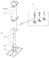
도 1은 본 고안에 따른 보조기구가 적용되는 비계를 나타내는 구성도
도 2는 본 고안의 제1실시예에 따른 보조기구를 나타내는 구성도
도 3은 본 고안의 제2실시예에 따른 보조기구를 나타내는 구성도1 is a schematic view showing a scaffold to which an auxiliary mechanism according to the present invention is applied
Fig. 2 is a configuration diagram showing a sub-mechanism according to the first embodiment of the present invention
3 is a configuration diagram showing a sub-mechanism according to a second embodiment of the present invention
이하, 첨부된 도면에 의거하여 본 고안의 실시예를 상세하게 설명하면 다음과 같다.Hereinafter, embodiments of the present invention will be described in detail with reference to the accompanying drawings.
본 고안은 비계(10)의 다리부재(20)를 리프팅하기 위한 보조기구에 관하여 제안한다. 도 1은 LNGC의 화물창에 단열박스를 부착하기 위한 고정식 시스템 발판을 예시하지만 본 고안이 반드시 이러한 비계(10)에 국한되는 것은 아니다. 비계(10)는 일정한 간격으로 배치되는 다수의 다리부재(20)를 이용하여 화물창의 바닥면 상에서 안정적인 자세를 유지한다. 이러한 다리부재(20)에서 내부레그(22)와 베이스플레이트(23)는 대략 65㎏의 하중이므로 화물창의 바닥면에 단열박스를 시공하려면 2명의 작업자가 다수개의 다리부재(20)에 대응하여 힘들게 들어 올리고 내리는 작업을 반복해야 한다.The present invention proposes an ancillary mechanism for lifting a leg member (20) of a scaffold (10). 1 illustrates a fixed system footplate for attaching an insulation box to a cargo hold of an LNGC, but the present invention is not necessarily limited to such a
본 고안에 의하면, 상기 다리부재(20)에서 동심으로 연결되는 외부레그(21)와 내부레그(22) 사이에 완충수단(30) 및 인상수단(40) 중 적어도 하나를 개재하는 구조이다. 내부레그(22)는 대부분이 외부레그(21)에 동심으로 수용되는 동시에 일부 노출되는 하단에서 베이스플레이트(23)와 연결된다. 완충수단(30) 및 인상수단(40)는 내부레그(22)와 베이스플레이트(23)를 들어 올리는 과정에서 하중을 경감하도록 설치된다. 완충수단(30) 및 인상수단(40)는 별개로 선택되어 설치될 수도 있고 후술하는 것처럼 상호 연계적으로 설치될 수도 있다.According to the present invention, at least one of the buffering means 30 and the lifting means 40 is interposed between the
이때, 외부레그(21)에는 하나의 핀홀(25)이 형성되고 내부레그(22)에는 상하로 다수의 핀홀(25)이 형성된다. 이에 베이스플레이트(23)를 1단의 높이로 올리고 해당 핀홀(25)에 핀을 결합한 상태에서 1층의 단열박스를 시공한 후 다시 내리며, 이후에 베이스플레이트(23)를 2단의 높이로 올리고 해당 핀홀(25)에 핀을 결합한 상태에서 2층의 단열박스를 시공한 후 다시 내린다.One
또, 본 고안에 의하면, 상기 완충수단(30) 및 인상수단(40)은 스프링의 탄성력을 기반으로 내부레그(22)의 리프팅 하중을 경감하는 구조를 지닌다. 스프링의 탄성력을 기반으로 하면 별도의 외부 동력을 배제하거나 최소한으로 의존하여 구성적으로 간편하다. 내부레그(22)의 리프팅 하중은 내부레그(22) 및 베이스플레이트(23)의 자중 외에 낙하의 충격력을 포함하는 의미이다. According to the present invention, the buffer means 30 and the lifting means 40 have a structure for reducing the lifting load of the
본 고안의 제1실시예로서, 상기 완충수단(30)은 스프링의 탄성력에 유압의 댐핑력을 부가하는 스프링댐퍼(32)를 사용하는 것을 특징으로 한다. 스프링댐퍼(32)는 시중의 표준품을 그대로 적용할 수 있으므로 다리부재(20)의 변형이 최소화된다. 도 2(a)는 내부레그(22)가 바닥면에 닿은 상태로서 내부레그(22)의 핀홀(25) 중에서 상단의 부호 25a에 핀이 체결되고 스프링댐퍼(32)는 다소 늘어난 상태이다. 도 2(b)는 내부레그(22)가 인상된 상태로서 핀홀(25) 중에서 하단의 부호 25b에 핀이 체결되고 스프링댐퍼(32)는 축소된 상태이다. 핀홀(25)에 핀을 체결하지 않은 상태(무부하)에서 베이스플레이트(23)가 바닥면에서 3~5㎝ 정도 이격되도록 스프링댐퍼(32)의 스프링상수를 설정한다.As a first embodiment of the present invention, the buffer means 30 uses a
이에, 도 2(a)에서 도 2(b)로 베이스플레이트(23)를 인상할 때 스프링의 탄성력에 의하여 하중을 경감하고, 도 2(b)에서 도 2(a)로 베이스플레이트(23)를 낙하시킬 때 유압의 댐핑력으로 충격을 완화한다.2 (a) to 2 (b), the load is reduced by the elastic force of the spring when the
본 고안의 세부 구성으로서, 상기 완충수단(30)은 지면에 대한 내부레그(22)의 하단 높이를 가변하도록 스프링댐퍼(32)의 상단부(34) 또는 하단부(36)에 나선의 맞물림 구조를 더 부가하는 것을 특징으로 한다. 스프링댐퍼(32)의 상단부(34)는 외부레그(21)의 상단에 고정되고, 하단부(36)는 내부레그(22)의 상단에 연결된다. 도시에는 생략하나 이러한 상단부(34) 또는 하단부(36)에 암수 나선의 맞물림 구조를 개재시키면 베이스플레이트(23)를 돌려서 무부하 상태에서 바닥면과의 높이를 가변할 수 있다. 이에 스프링댐퍼(32)에 연결된 내부레그(22) 및 베이스플레이트(23)의 상하운동과 관련된 힘을 조정할 수 있다.As a detailed configuration of the present invention, the buffer means 30 has a helical engagement structure on the
본 고안의 제2실시예로서, 상기 인상수단(40)은 메인스프링(41)의 탄성력에 에어실린더(43)와 피스톤(44)에 의한 인상력을 부가하는 것을 특징으로 한다. 도 3에서 스프링댐퍼(32) 대신에 메인스프링(41)을 상단부(34) 및 하단부(36)에서 고정하고, 메인스프링(41)의 상단부(34)에 피스톤(44)을 지닌 에어실린더(43)를 개재시킨다. 이에, 통상적으로 작업 현장에 제공되는 공압라인의 공압건(도시 생략)을 연결하여 에어실린더(43)에 공압력을 작용하면 피스톤(44)에 연결된 메인스프링(41)과 내부레그(22)가 상승한다.As a second embodiment of the present invention, the lifting means (40) is characterized by adding a pulling force by the air cylinder (43) and the piston (44) to the elastic force of the main spring (41). The
본 고안의 세부 구성으로서, 상기 인상수단(40)은 에어실린더(43)의 포트(45)가 외부레그(21)로 노출되도록 설치하고, 포트(45) 상에 공기의 출입을 단속하는 밸브를 구비하는 것을 특징으로 한다. 에어실린더(43)의 포트(45)는 공압건을 착탈하기 충분할 정도로 외부레그(21)의 표면에서 노출시킨다. 포트(45)의 밸브는 유로 개폐를 위한 레버를 구비하는 외에, 공압건의 연결에 의해 유로를 개방하고 공압건의 분리에 의해 유로를 폐쇄한다. 밸브의 기밀력은 높게 요구되지 않는다. 즉, 에어실린더(43)에 공기를 넣어 베이스플레이트(23)가 상승된 상태에서 서서히 낙하되더라도 핀홀(25)에 핀을 연결하는 작업이 가능하다.As a detailed configuration of the present invention, the lifting means 40 is provided so that the
이때, 에어실린더(43)는 피스톤(44) 상에 서브스프링(47)을 탑재한 방식을 사용할 수도 있다. 이는 에어실린더(43)의 에어를 배출하는 과정에서 베이스플레이트(23)의 급격한 낙하에 의한 충격을 완화한다.At this time, the
한편, 도시에는 생략하나 메인스프링(41)의 위치에 전술한 스프링댐퍼(32)를 적용하는 구성도 가능하다. 즉, 완충수단(30) 및 인상수단(40)을 상호 연계적으로 설치할 수 있음을 의미한다.On the other hand, the
본 고안은 기재된 실시예에 한정되는 것은 아니고, 본 고안의 사상 및 범위를 벗어나지 않고 다양하게 수정 및 변형할 수 있음은 이 기술의 분야에서 통상의 지식을 가진 자에게 자명하다. 따라서 그러한 변형예 또는 수정예들은 본 고안의 실용신안등록청구범위에 속한다 해야 할 것이다.It will be apparent to those skilled in the art that various modifications and variations can be made in the present invention without departing from the spirit and scope of the invention as defined by the appended claims. Accordingly, such variations or modifications should fall within the scope of the utility model registration claims of the present invention.
10: 비계
20: 다리부재
21: 외부레그
22: 내부레그
23: 베이스플레이트
25: 핀홀
30: 완충수단
32: 스프링댐퍼
34: 상단부
36: 하단부
40: 인상수단
41: 메인스프링
43: 에어실린더
44: 피스톤
45: 포트
47: 서브스프링10: Scaffold 20: Leg member
21: outer leg 22: inner leg
23: base plate 25: pinhole
30: buffer means 32: spring damper
34: upper end 36: lower end
40: lifting means 41: main spring
43: air cylinder 44: piston
45: Port 47: Sub spring
Claims (5)
상기 다리부재(20)에서 동심으로 연결되는 외부레그(21)와 내부레그(22) 사이에 완충수단(30) 및 인상수단(40) 중 적어도 하나를 개재하되,
상기 완충수단(30) 및 인상수단(40)은 스프링의 탄성력을 기반으로 내부레그(22)의 리프팅 하중을 경감하는 것을 특징으로 하는 레그 리프팅을 위한 보조기구.An auxiliary mechanism for lifting a leg member (20) of a scaffold (10) comprising:
At least one of the buffering means (30) and the lifting means (40) is interposed between the outer leg (21) and the inner leg (22) concentrically connected by the leg member (20)
Characterized in that the buffer means (30) and the lifting means (40) relieve the lifting load of the inner leg (22) based on the elastic force of the spring.
상기 완충수단(30)은 스프링의 탄성력에 유압의 댐핑력을 부가하는 스프링댐퍼(32)를 사용하는 것을 특징으로 하는 레그 리프팅을 위한 보조기구.The method according to claim 1,
Characterized in that the buffer means (30) uses a spring damper (32) which adds a hydraulic damping force to the elastic force of the spring.
상기 완충수단(30)은 지면에 대한 내부레그(22)의 하단 높이를 가변하도록 스프링댐퍼(32)의 상단부(34) 또는 하단부(36)에 나선의 맞물림 구조를 더 부가하는 것을 특징으로 하는 레그 리프팅을 위한 보조기구.The method according to claim 1,
Characterized in that the buffering means (30) further comprises a helical engagement structure on the upper end (34) or the lower end (36) of the spring damper (32) to vary the height of the lower end of the inner leg (22) Aids for lifting.
상기 인상수단(40)은 메인스프링(41)의 탄성력에 에어실린더(43)와 피스톤(44)에 의한 인상력을 부가하는 것을 특징으로 하는 레그 리프팅을 위한 보조기구.The method according to claim 1,
Characterized in that the lifting means (40) adds a pulling force by the air cylinder (43) and the piston (44) to the elastic force of the main spring (41).
상기 인상수단(40)은 에어실린더(43)의 포트(45)가 외부레그(21)로 노출되도록 설치하고, 포트(45) 상에 공기의 출입을 단속하는 밸브를 구비하는 것을 특징으로 하는 레그 리프팅을 위한 보조기구.The method according to claim 1,
Characterized in that the lifting means (40) is provided with a valve which is provided so that the port (45) of the air cylinder (43) is exposed to the outer leg (21) Aids for lifting.
Priority Applications (1)
| Application Number | Priority Date | Filing Date | Title |
|---|---|---|---|
| KR2020160003544U KR200492304Y1 (en) | 2016-06-22 | 2016-06-22 | Assistant Device for Leg lifting |
Applications Claiming Priority (1)
| Application Number | Priority Date | Filing Date | Title |
|---|---|---|---|
| KR2020160003544U KR200492304Y1 (en) | 2016-06-22 | 2016-06-22 | Assistant Device for Leg lifting |
Publications (2)
| Publication Number | Publication Date |
|---|---|
| KR20180000009U true KR20180000009U (en) | 2018-01-02 |
| KR200492304Y1 KR200492304Y1 (en) | 2020-09-15 |
Family
ID=61275079
Family Applications (1)
| Application Number | Title | Priority Date | Filing Date |
|---|---|---|---|
| KR2020160003544U Expired - Lifetime KR200492304Y1 (en) | 2016-06-22 | 2016-06-22 | Assistant Device for Leg lifting |
Country Status (1)
| Country | Link |
|---|---|
| KR (1) | KR200492304Y1 (en) |
Cited By (2)
| Publication number | Priority date | Publication date | Assignee | Title |
|---|---|---|---|---|
| CN115823411A (en) * | 2022-12-03 | 2023-03-21 | 江苏速捷模架科技有限公司 | Support leg system of building envelope system construction platform module and use method thereof |
| CN118007918A (en) * | 2024-04-09 | 2024-05-10 | 陕西惠延机械有限公司 | Tunnel construction template supporting bench system |
Citations (4)
| Publication number | Priority date | Publication date | Assignee | Title |
|---|---|---|---|---|
| KR20000016594A (en) | 1996-06-13 | 2000-03-25 | 미쉘 지. 멘지니 | Packaging system for storing and dividing products |
| KR20080103475A (en) * | 2008-08-11 | 2008-11-27 | 남주희 | Elastic Pin Jig for Ship Block Stand |
| KR20100040382A (en) | 2008-10-10 | 2010-04-20 | 대우조선해양 주식회사 | Movable scaffolding structure for working of cargo hold in lng carrier |
| KR20110001608U (en) * | 2009-08-10 | 2011-02-17 | (주)엘티 | Apparauts for assisting in rise and fall of pin-jig and pin-jig using the same |
-
2016
- 2016-06-22 KR KR2020160003544U patent/KR200492304Y1/en not_active Expired - Lifetime
Patent Citations (4)
| Publication number | Priority date | Publication date | Assignee | Title |
|---|---|---|---|---|
| KR20000016594A (en) | 1996-06-13 | 2000-03-25 | 미쉘 지. 멘지니 | Packaging system for storing and dividing products |
| KR20080103475A (en) * | 2008-08-11 | 2008-11-27 | 남주희 | Elastic Pin Jig for Ship Block Stand |
| KR20100040382A (en) | 2008-10-10 | 2010-04-20 | 대우조선해양 주식회사 | Movable scaffolding structure for working of cargo hold in lng carrier |
| KR20110001608U (en) * | 2009-08-10 | 2011-02-17 | (주)엘티 | Apparauts for assisting in rise and fall of pin-jig and pin-jig using the same |
Cited By (2)
| Publication number | Priority date | Publication date | Assignee | Title |
|---|---|---|---|---|
| CN115823411A (en) * | 2022-12-03 | 2023-03-21 | 江苏速捷模架科技有限公司 | Support leg system of building envelope system construction platform module and use method thereof |
| CN118007918A (en) * | 2024-04-09 | 2024-05-10 | 陕西惠延机械有限公司 | Tunnel construction template supporting bench system |
Also Published As
| Publication number | Publication date |
|---|---|
| KR200492304Y1 (en) | 2020-09-15 |
Similar Documents
| Publication | Publication Date | Title |
|---|---|---|
| CN106760583B (en) | Multifunctional safety protection device for high-rise building construction | |
| CN208594486U (en) | A kind of anchor ear system of automatic lifting | |
| CN107496129A (en) | A kind of medical bed | |
| CN215055067U (en) | Platform device for slope construction | |
| CN208918545U (en) | A kind of extension type tunnel excavation operation platform | |
| KR200492304Y1 (en) | Assistant Device for Leg lifting | |
| CN110255427A (en) | A simple lifting auxiliary device with clamping function | |
| JP2016056000A (en) | Workpiece lifting device | |
| KR101144922B1 (en) | ladder up and down Device for vessel | |
| CN208152519U (en) | A kind of building decoration construction lifting mechanism | |
| KR100640296B1 (en) | Elevated scaffolding device for working inside the hopper block of a ship | |
| JP4310583B2 (en) | Steel tower lifting device | |
| CN109322499A (en) | A kind of adjustable brick-laying machine of rotary kiln | |
| US9909373B2 (en) | Well rod string penetration adjustment apparatus and method | |
| KR20150051859A (en) | Multistage lifting apparatus and movable stage using the same | |
| CN209442584U (en) | A kind of movable base and the hoistable platform with the pedestal | |
| KR200493312Y1 (en) | Working Platform for Lift having Extendable Wall | |
| KR200454194Y1 (en) | Lifting aid for pin jig and pin jig using the same | |
| CN206605468U (en) | A kind of plant equipment inspection rack structure | |
| KR20150000315U (en) | block support | |
| CN218348378U (en) | Anti-toppling electrical panel cabinet | |
| CN207161875U (en) | A kind of valve buttress applied to long distance pipeline yard | |
| CN110258629A (en) | The assembled equipment and its assembling method of prefabricated components | |
| CN221588050U (en) | Movable operation platform for electromechanical installation | |
| CN206568320U (en) | A kind of prefabricated case beam tensioning car |
Legal Events
| Date | Code | Title | Description |
|---|---|---|---|
| UA0108 | Application for utility model registration |
St.27 status event code: A-0-1-A10-A12-nap-UA0108 |
|
| R18-X000 | Changes to party contact information recorded |
St.27 status event code: A-3-3-R10-R18-oth-X000 |
|
| UG1501 | Laying open of application |
St.27 status event code: A-1-1-Q10-Q12-nap-UG1501 |
|
| A201 | Request for examination | ||
| UA0201 | Request for examination |
St.27 status event code: A-1-2-D10-D11-exm-UA0201 |
|
| D13-X000 | Search requested |
St.27 status event code: A-1-2-D10-D13-srh-X000 |
|
| D14-X000 | Search report completed |
St.27 status event code: A-1-2-D10-D14-srh-X000 |
|
| P22-X000 | Classification modified |
St.27 status event code: A-2-2-P10-P22-nap-X000 |
|
| P22-X000 | Classification modified |
St.27 status event code: A-2-2-P10-P22-nap-X000 |
|
| E902 | Notification of reason for refusal | ||
| UE0902 | Notice of grounds for rejection |
St.27 status event code: A-1-2-D10-D21-exm-UE0902 |
|
| E13-X000 | Pre-grant limitation requested |
St.27 status event code: A-2-3-E10-E13-lim-X000 |
|
| P11-X000 | Amendment of application requested |
St.27 status event code: A-2-2-P10-P11-nap-X000 |
|
| P13-X000 | Application amended |
St.27 status event code: A-2-2-P10-P13-nap-X000 |
|
| E701 | Decision to grant or registration of patent right | ||
| UE0701 | Decision of registration |
St.27 status event code: A-1-2-D10-D22-exm-UE0701 |
|
| REGI | Registration of establishment | ||
| UR0701 | Registration of establishment |
St.27 status event code: A-2-4-F10-F11-exm-UR0701 |
|
| UR1002 | Payment of registration fee |
St.27 status event code: A-2-2-U10-U11-oth-UR1002 Fee payment year number: 1 |
|
| UG1601 | Publication of registration |
St.27 status event code: A-4-4-Q10-Q13-nap-UG1601 |
|
| R18-X000 | Changes to party contact information recorded |
St.27 status event code: A-5-5-R10-R18-oth-X000 |
|
| UN2301 | Change of applicant |
St.27 status event code: A-5-5-R10-R13-asn-UN2301 St.27 status event code: A-5-5-R10-R11-asn-UN2301 |
|
| UR1001 | Payment of annual fee |
St.27 status event code: A-4-4-U10-U11-oth-UR1001 Fee payment year number: 4 |
|
| UR1001 | Payment of annual fee |
St.27 status event code: A-4-4-U10-U11-oth-UR1001 Fee payment year number: 5 |
|
| U11 | Full renewal or maintenance fee paid |
Free format text: ST27 STATUS EVENT CODE: A-4-4-U10-U11-OTH-UR1001 (AS PROVIDED BY THE NATIONAL OFFICE) Year of fee payment: 6 |
|
| UR1001 | Payment of annual fee |
St.27 status event code: A-4-4-U10-U11-oth-UR1001 Fee payment year number: 6 |