KR20180052257A - Greenhouse dehumidifier and greenhouse dehumidifying system using the same - Google Patents
Greenhouse dehumidifier and greenhouse dehumidifying system using the same Download PDFInfo
- Publication number
- KR20180052257A KR20180052257A KR1020160149374A KR20160149374A KR20180052257A KR 20180052257 A KR20180052257 A KR 20180052257A KR 1020160149374 A KR1020160149374 A KR 1020160149374A KR 20160149374 A KR20160149374 A KR 20160149374A KR 20180052257 A KR20180052257 A KR 20180052257A
- Authority
- KR
- South Korea
- Prior art keywords
- greenhouse
- dry air
- air
- temperature
- dehumidifier
- Prior art date
- Legal status (The legal status is an assumption and is not a legal conclusion. Google has not performed a legal analysis and makes no representation as to the accuracy of the status listed.)
- Granted
Links
Images


Classifications
-
- A—HUMAN NECESSITIES
- A01—AGRICULTURE; FORESTRY; ANIMAL HUSBANDRY; HUNTING; TRAPPING; FISHING
- A01G—HORTICULTURE; CULTIVATION OF VEGETABLES, FLOWERS, RICE, FRUIT, VINES, HOPS OR SEAWEED; FORESTRY; WATERING
- A01G9/00—Cultivation in receptacles, forcing-frames or greenhouses; Edging for beds, lawn or the like
- A01G9/24—Devices or systems for heating, ventilating, regulating temperature, illuminating, or watering, in greenhouses, forcing-frames, or the like
- A01G9/246—Air-conditioning systems
-
- F—MECHANICAL ENGINEERING; LIGHTING; HEATING; WEAPONS; BLASTING
- F24—HEATING; RANGES; VENTILATING
- F24F—AIR-CONDITIONING; AIR-HUMIDIFICATION; VENTILATION; USE OF AIR CURRENTS FOR SCREENING
- F24F11/00—Control or safety arrangements
- F24F11/0008—Control or safety arrangements for air-humidification
-
- F—MECHANICAL ENGINEERING; LIGHTING; HEATING; WEAPONS; BLASTING
- F24—HEATING; RANGES; VENTILATING
- F24F—AIR-CONDITIONING; AIR-HUMIDIFICATION; VENTILATION; USE OF AIR CURRENTS FOR SCREENING
- F24F11/00—Control or safety arrangements
- F24F11/30—Control or safety arrangements for purposes related to the operation of the system, e.g. for safety or monitoring
-
- F—MECHANICAL ENGINEERING; LIGHTING; HEATING; WEAPONS; BLASTING
- F24—HEATING; RANGES; VENTILATING
- F24F—AIR-CONDITIONING; AIR-HUMIDIFICATION; VENTILATION; USE OF AIR CURRENTS FOR SCREENING
- F24F11/00—Control or safety arrangements
- F24F11/70—Control systems characterised by their outputs; Constructional details thereof
- F24F11/80—Control systems characterised by their outputs; Constructional details thereof for controlling the temperature of the supplied air
- F24F11/83—Control systems characterised by their outputs; Constructional details thereof for controlling the temperature of the supplied air by controlling the supply of heat-exchange fluids to heat-exchangers
-
- F—MECHANICAL ENGINEERING; LIGHTING; HEATING; WEAPONS; BLASTING
- F24—HEATING; RANGES; VENTILATING
- F24F—AIR-CONDITIONING; AIR-HUMIDIFICATION; VENTILATION; USE OF AIR CURRENTS FOR SCREENING
- F24F3/00—Air-conditioning systems in which conditioned primary air is supplied from one or more central stations to distributing units in the rooms or spaces where it may receive secondary treatment; Apparatus specially designed for such systems
- F24F3/06—Air-conditioning systems in which conditioned primary air is supplied from one or more central stations to distributing units in the rooms or spaces where it may receive secondary treatment; Apparatus specially designed for such systems characterised by the arrangements for the supply of heat-exchange fluid for the subsequent treatment of primary air in the room units
-
- F—MECHANICAL ENGINEERING; LIGHTING; HEATING; WEAPONS; BLASTING
- F24—HEATING; RANGES; VENTILATING
- F24F—AIR-CONDITIONING; AIR-HUMIDIFICATION; VENTILATION; USE OF AIR CURRENTS FOR SCREENING
- F24F3/00—Air-conditioning systems in which conditioned primary air is supplied from one or more central stations to distributing units in the rooms or spaces where it may receive secondary treatment; Apparatus specially designed for such systems
- F24F3/12—Air-conditioning systems in which conditioned primary air is supplied from one or more central stations to distributing units in the rooms or spaces where it may receive secondary treatment; Apparatus specially designed for such systems characterised by the treatment of the air otherwise than by heating and cooling
- F24F3/14—Air-conditioning systems in which conditioned primary air is supplied from one or more central stations to distributing units in the rooms or spaces where it may receive secondary treatment; Apparatus specially designed for such systems characterised by the treatment of the air otherwise than by heating and cooling by humidification; by dehumidification
-
- F—MECHANICAL ENGINEERING; LIGHTING; HEATING; WEAPONS; BLASTING
- F24—HEATING; RANGES; VENTILATING
- F24F—AIR-CONDITIONING; AIR-HUMIDIFICATION; VENTILATION; USE OF AIR CURRENTS FOR SCREENING
- F24F2110/00—Control inputs relating to air properties
- F24F2110/10—Temperature
-
- Y—GENERAL TAGGING OF NEW TECHNOLOGICAL DEVELOPMENTS; GENERAL TAGGING OF CROSS-SECTIONAL TECHNOLOGIES SPANNING OVER SEVERAL SECTIONS OF THE IPC; TECHNICAL SUBJECTS COVERED BY FORMER USPC CROSS-REFERENCE ART COLLECTIONS [XRACs] AND DIGESTS
- Y02—TECHNOLOGIES OR APPLICATIONS FOR MITIGATION OR ADAPTATION AGAINST CLIMATE CHANGE
- Y02A—TECHNOLOGIES FOR ADAPTATION TO CLIMATE CHANGE
- Y02A40/00—Adaptation technologies in agriculture, forestry, livestock or agroalimentary production
- Y02A40/10—Adaptation technologies in agriculture, forestry, livestock or agroalimentary production in agriculture
- Y02A40/25—Greenhouse technology, e.g. cooling systems therefor
Landscapes
- Engineering & Computer Science (AREA)
- Chemical & Material Sciences (AREA)
- Combustion & Propulsion (AREA)
- Mechanical Engineering (AREA)
- General Engineering & Computer Science (AREA)
- Life Sciences & Earth Sciences (AREA)
- Environmental Sciences (AREA)
- Greenhouses (AREA)
Abstract
본 발명은 온실의 습도를 제어하기 위한 온실 제습 장치에 있어서, 건조 공기를 저장하는 저장탱크, 상기 저장탱크와 연결되어 상기 건조 공기를 이송하는 이송관 및 상기 이송관을 통해 이송되는 상기 건조 공기를 식물로 배출하는 배출부를 포함하는 온실 제습 장치를 제공한다.The present invention relates to a greenhouse dehumidifier for controlling the humidity of a greenhouse, comprising: a storage tank for storing dry air; a transfer pipe connected to the storage tank for transferring the dry air; And a discharge portion for discharging the greenhouse dehumidifier to plants.
Description
실시예는 온실 제습 장치 및 이를 이용한 온실 제습 시스템에 관한 것이다. 보다 상세하게는, 제습 장치를 이용하여 여러 상대습도를 가지는 건조 공기를 저장탱크에 저장한 후, 필요한 시기에 이를 공급하여 온실 내부의 습도를 유지하는 온실 제습 장치 및 이를 이용한 온실 제습 시스템에 관한 것이다.The present invention relates to a greenhouse dehumidifier and a greenhouse dehumidifier using the same. More particularly, the present invention relates to a greenhouse dehumidifier for storing dry air having various relative humidity using a dehumidifying device in a storage tank and supplying the dried air at a required time to maintain the humidity inside the greenhouse, and a greenhouse dehumidification system using the same .
일반적으로 온실은 식물의 생육에 중요한 영향을 미치는 습도를 제어하기 위해 온실 내부의 환기나 온도 제어를 통한 상대습도 제어 방식을 사용하고 있다. 온도를 제어하는 습도 제어 방식은 온실 내부의 식물에 미치는 온도의 영향 또한 고려해야 하므로 온도 변동 폭에 대한 제약이 있다. 이러한 방식은 온도 변동을 통한 상대습도를 제어하여도 원하는 습도 조건을 만족시키지 못하는 경우 환기를 통해 외기를 온실 내부로 유입하여 전체적인 습도를 제어하는 방식을 사용하고 있다.Generally, the greenhouse uses a relative humidity control method through ventilation inside the greenhouse or temperature control to control the humidity, which has an important influence on the growth of the plant. The humidity control method that controls the temperature has a limitation on the temperature fluctuation width since the influence of the temperature on the plants inside the greenhouse must also be considered. This method uses a method of controlling the overall humidity by introducing the outside air into the greenhouse through ventilation when the relative humidity through the temperature fluctuation is controlled but the desired humidity condition is not satisfied.
그러나, 외기를 유입하는 방식은 동절기와 같이 외기의 온도 조건이 온실 내 재배 식물의 생장에 치명적인 영향을 끼칠 수 있는 조건인 경우에는 환기를 통한 습도 제어 또한 불가능해진다는 문제점이 있다. 부득이한 경우 환기를 통한 온도저하를 만회하기 위해 난방을 병행할 수 있으나, 막대한 난방비가 수반되므로 불가피한 경우를 제외하고는 적용하기가 어렵다.However, there is a problem in that, when the temperature condition of the outside air such as the winter season is a condition that can adversely affect the growth of cultivated plants in the greenhouse, the method of introducing the outside air can not control the humidity through ventilation. Inevitably, heating can be performed in parallel to compensate for the temperature drop through ventilation, but it is difficult to apply except for unavoidable cases because it involves massive heating costs.
따라서, 상대습도를 낮추기 위해 난방을 하거나, 환기로 인해 떨어진 온실의 온도를 재승온하는 등의 온실의 난방 부하를 키우지 않고 적정한 습도 조건을 유연하게 달성할 수 있는 보다 효율적인 제습 방안의 필요성이 대두되고 있다.Therefore, there is a need for a more efficient dehumidification scheme capable of flexibly achieving an appropriate humidity condition without increasing the heating load of the greenhouse, such as heating to lower the relative humidity or re-establishing the temperature of the greenhouse away from the ventilation have.
이러한, 문제를 해결하기 위해 별도의 제습 설비를 이용하여 온실 내부의 습도를 제어하는 방안이 등장하고 있다. 그러나 제습 설비를 이용하는 습도 조절 방법은 온실의 내부공간을 제한된 시간 안에 제습하기 위해서는 막대한 크기의 설비용량을 갖춰야 하며, 이에 소요되는 필요 에너지 비용과 설비 비용 부담으로 인해 중대규모의 온실에 적용하는데 경제적 문제점이 발생한다.In order to solve such a problem, a method of controlling the humidity inside the greenhouse using a separate dehumidifying facility has appeared. However, the humidity control method using the dehumidification facility requires a large-sized facility capacity to dehumidify the internal space of the greenhouse within a limited time, and it is necessary to apply the energy cost and equipment cost to the greenhouse Lt; / RTI >
또한, 제습 장치를 통해 생산된 건조 공기를 공급함에 있어서, 온실 내 특정위치에서 제한된 배기면적을 통해 건조 공기를 온실 내로 공급할 경우 온실 전체의 습도를 낮추는데 상당한 시간이 소요되므로 재배하고 있는 식물이 위치한 공간을 대상으로 신속한 제습이 이뤄질 수 있는 방식의 고안이 필요하다.In addition, when supplying dry air produced by the dehumidifier to the greenhouse through a limited exhaust area at a specific position in the greenhouse, it takes a considerable time to lower the humidity of the entire greenhouse. Therefore, It is necessary to devise a way that rapid dehumidification can be achieved.
실시예는 제습 장치를 이용하여 여러 상대습도를 가지는 건조 공기를 저장탱크에 저장한 후, 필요한 시기에 이를 공급하여 온실 내부의 습도를 유지하는 온실 제습 장치 및 이를 이용한 온실 제습 시스템을 제공한다.The present invention provides a greenhouse dehumidifier and a greenhouse dehumidification system using the same, in which dry air having various relative humidity is stored in a storage tank by using a dehumidifier and then supplied at a required time to maintain the humidity inside the greenhouse.
본 발명이 해결하고자 하는 과제는 이상에서 언급된 과제에 국한되지 않으며 여기서 언급되지 않은 또 다른 과제들은 아래의 기재로부터 당업자에게 명확하게 이해될 수 있을 것이다.The problems to be solved by the present invention are not limited to the above-mentioned problems, and other problems not mentioned here can be understood by those skilled in the art from the following description.
본 발명의 실시예는, 온실의 습도를 제어하기 위한 온실 제습 장치에 있어서, 건조 공기를 저장하는 저장탱크; 상기 저장탱크와 연결되어 상기 건조 공기를 이송하는 이송관; 및 상기 이송관을 통해 이송되는 상기 건조 공기를 식물로 배출하는 배출부;를 포함하며, 상기 저장탱크는 제습기와 연결되어, 상기 제습기를 통해 건조된 공기가 저장되는 것을 특징으로 한다.An embodiment of the present invention is a greenhouse dehumidifier for controlling the humidity of a greenhouse, comprising: a storage tank for storing dry air; A transfer pipe connected to the storage tank for transferring the dry air; And a discharge unit for discharging the dry air conveyed through the transfer pipe to a plant, wherein the storage tank is connected to a dehumidifier, and the air dried through the dehumidifier is stored.
상기 저장탱크는 복수로 마련되며, 복수의 상기 저장탱크에는 서로 다른 습도를 가지는 건조 공기가 저장되는 것을 특징으로 할 수 있다.The plurality of storage tanks may be provided, and dry air having a different humidity may be stored in the plurality of storage tanks.
상기 배출부에는 상기 건조 공기의 온도를 조절하는 온도조절기가 연결되는 것을 특징으로 할 수 있다.And a temperature controller for controlling the temperature of the drying air is connected to the discharge unit.
상기 온도조절기는, 상기 배출부에 가열코일이 연결되어 상기 건조 공기를 가열하는 것을 특징으로 할 수 있다.The temperature controller may further include a heating coil connected to the discharge unit to heat the drying air.
상기 배출부는 온실의 바닥 쪽에서 식물을 향해 건조 공기를 분사하는 것을 특징으로 할 수 있다.And the discharge unit may discharge dry air from the bottom side of the greenhouse toward the plant.
본 발명의 또 다른 실시 예는, 서로 다른 습도의 공기가 저장되는 복수의 건조 공기 저장부; 상기 건조 공기 저장부로 건조 공기를 공급하는 제습부; 및 온실의 내부 정보에 기초하여 상기 건조 공기의 공급여부를 제어하는 제어부;를 포함하며, 상기 제어부는 온실 내부에 제습이 필요로 하지 않은 시기에 상기 제습부를 구동하여 상기 건조 공기 저장부에 건조 공기를 저장하는 것을 특징으로 한다.Yet another embodiment of the present invention is directed to an air conditioning system comprising: a plurality of dry air storage units for storing air of different humidity; A dehumidifying part for supplying dry air to the dry air storage part; And a control unit for controlling whether or not the dry air is supplied based on the internal information of the greenhouse, wherein the controller drives the dehumidifying unit at a time when dehumidification is not required in the greenhouse, Is stored.
온실 내부의 공기량을 조절하는 유량조절부;를 더 포함하며, 상기 유량조절부는 온실 내부로 공급되는 건조 공기의 양을 측정하고, 측정된 양만큼 온실 내부의 습한 공기를 송풍장치를 이용하여 온실 외부로 방출하는 것을 특징으로 할 수 있다.The flow rate control unit measures the amount of dry air supplied to the inside of the greenhouse and measures the amount of the humid air in the greenhouse by the measured amount to the exterior of the greenhouse using a blower, As shown in FIG.
상기 온실로 공급되는 건조 공기의 온도를 조절하는 온도조절부;를 더 포함하며, 상기 온도조절부는 건조 공기가 배출되는 식물 주변의 온도를 측정하고 이에 따라 건조 공기의 온도를 조절하는 것을 특징으로 할 수 있다.And a temperature regulator for regulating the temperature of the dry air supplied to the greenhouse, wherein the temperature regulator measures the temperature around the plant where the dry air is discharged and adjusts the temperature of the dry air accordingly .
상기 제어부는 상기 온실 내부에서 얻어진 정보를 이용하여, 작물에 필요로 하는 습도의 건조 공기를 상기 건조 공기 저장부에서 선택하여 상기 온실 내부로 공급하는 것을 특징으로 할 수 있다.And the controller selects the dry air having the humidity required for the crop from the dry air storage unit using the information obtained inside the greenhouse, and supplies the dry air to the inside of the greenhouse.
실시예에 따르면, 제습에 필요한 과도한 난방비용을 줄일 수 있는 효과가 있다.According to the embodiment, it is possible to reduce the excessive heating cost required for dehumidification.
또한, 제습이 필요한 국부적이 공간을 대상으로 한 치환방식을 이용하여 식물 생장에 나쁜 영향을 미치는 외부 교란을 최소화하여 작물의 생산성을 향상시킬 수 있는 효과가 있다.In addition, it is possible to minimize the external disturbance which adversely affects the plant growth by using the substitution method for the local space requiring dehumidification, thereby improving the productivity of the crop.
또한, 순간적인 제습 효과를 달성하는데 소요되는 시간을 대폭 감소시켜 작물 생장에 필요한 습도의 최적 제어가 가능해진다.In addition, the time required to achieve the instantaneous dehumidification effect is greatly reduced, and the optimum humidity control required for crop growth can be achieved.
본 발명의 다양하면서도 유익한 장점과 효과는 상술한 내용에 한정되지 않으며, 본 발명의 구체적인 실시형태를 설명하는 과정에서 보다 쉽게 이해될 수 있을 것이다.The various and advantageous advantages and effects of the present invention are not limited to the above description, and can be more easily understood in the course of describing a specific embodiment of the present invention.
도 1은 본 발명의 실시 예에 따른 온실 제습 장치의 전체 구조를 나타내는 도면이고,
도 2는 도 1에서 온실 내부에 설치되는 구조를 나타내는 도면이고,
도 3은 도 2에서 이송관의 배치구조를 나타내는 도면이고,
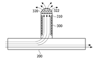
도 4는 도 2에서 배출부의 구조를 나타내는 도면이고,
도 5는 본 발명의 또 다른 실시 예에 따른 온실 제습 시스템의 블록도이다.1 is a view showing the entire structure of a greenhouse dehumidifier according to an embodiment of the present invention,
FIG. 2 is a view showing a structure installed in a greenhouse in FIG. 1,
FIG. 3 is a view showing the arrangement structure of the transfer pipe in FIG. 2,
Fig. 4 is a view showing the structure of the discharge portion in Fig. 2,
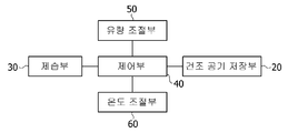
5 is a block diagram of a greenhouse dehumidification system according to another embodiment of the present invention.
본 발명은 다양한 변경을 가할 수 있고 여러 가지 실시 예를 가질 수 있는 바, 특정 실시 예를 도면에 예시하고 설명하고자 한다. 그러나, 이는 본 발명 실시 예를 특정한 실시 형태에 대해 한정하려는 것이 아니며, 실시 예의 사상 및 기술 범위에 포함되는 모든 변경, 균등물 내지 대체물을 포함하는 것으로 이해되어야 한다.While the invention is susceptible to various modifications and alternative forms, specific embodiments thereof are shown by way of example in the drawings and will herein be described in detail. It should be understood, however, that the embodiments of the present invention are not intended to be limited to the specific embodiments but include all modifications, equivalents, and alternatives falling within the spirit and scope of the embodiments.
제 1, 제 2 등과 같이 서수를 포함하는 용어는 다양한 구성 요소들을 설명하는데 사용될 수 있지만, 상기 구성 요소들은 상기 용어들에 의해 한정되지는 않는다. 상기 용어들은 하나의 구성 요소를 다른 구성 요소로부터 구별하는 목적으로만 사용된다. 예를 들어, 실시 예의 권리 범위를 벗어나지 않으면서 제 2 구성 요소는 제 1 구성 요소로 명명될 수 있고, 유사하게 제 1 구성 요소도 제 2 구성 요소로 명명될 수 있다. 및/또는 이라는 용어는 복수의 관련된 기재된 항목들의 조합 또는 복수의 관련된 기재된 항목들 중의 어느 항목을 포함한다.Terms including ordinals, such as first, second, etc., may be used to describe various elements, but the elements are not limited to these terms. The terms are used only for the purpose of distinguishing one component from another. For example, without departing from the scope of the embodiments, the second component may be referred to as a first component, and similarly, the first component may also be referred to as a second component. And / or < / RTI > includes any combination of a plurality of related listed items or any of a plurality of related listed items.
본 출원에서 사용한 용어는 단지 특정한 실시 예를 설명하기 위해 사용된 것으로, 본 발명 실시 예를 한정하려는 의도가 아니다. 단수의 표현은 문맥상 명백하게 다르게 뜻하지 않는 한, 복수의 표현을 포함한다. 본 출원에서, "포함하다" 또는 "가지다" 등의 용어는 명세서상에 기재된 특징, 숫자, 단계, 동작, 구성 요소, 부품 또는 이들을 조합한 것이 존재함을 지정하려는 것이지, 하나 또는 그 이상의 다른 특징들이나 숫자, 단계, 동작, 구성 요소, 부품 또는 이들을 조합한 것들의 존재 또는 부가 가능성을 미리 배제하지 않는 것으로 이해되어야 한다.The terminology used herein is for the purpose of describing particular embodiments only and is not intended to limit the embodiments of the invention. The singular expressions include plural expressions unless the context clearly dictates otherwise. In the present application, the terms "comprises" or "having" and the like are used to specify that there is a feature, a number, a step, an operation, an element, a component or a combination thereof described in the specification, But do not preclude the presence or addition of one or more other features, integers, steps, operations, elements, components, or combinations thereof.
실시 예의 설명에 있어서, 어느 한 element가 다른 element의 "상(위) 또는 하(아래)(on or under)"에 형성되는 것으로 기재되는 경우에 있어, 상(위) 또는 하(아래)(on or under)는 두 개의 element가 서로 직접(directly)접촉되거나 하나 이상의 다른 element가 상기 두 element 사이에 배치되어(indirectly) 형성되는 것을 모두 포함한다. 또한 "상(위) 또는 하(아래)(on or under)"으로 표현되는 경우 하나의 element를 기준으로 위쪽 방향뿐만 아니라 아래쪽 방향의 의미도 포함할 수 있다.In the description of the embodiments, in the case where one element is described as being formed "on or under" another element, the upper (upper) or lower (lower) or under are all such that two elements are in direct contact with each other or one or more other elements are indirectly formed between the two elements. Also, when expressed as "on or under", it may include not only an upward direction but also a downward direction with respect to one element.
이하, 첨부된 도면을 참조하여 실시 예를 상세히 설명하되, 도면 부호에 관계없이 동일하거나 대응하는 구성 요소는 동일한 참조 번호를 부여하고 이에 대한 중복되는 설명은 생략하기로 한다.Hereinafter, embodiments will be described in detail with reference to the accompanying drawings, wherein like or corresponding elements are denoted by the same reference numerals, and redundant description thereof will be omitted.
도 1 내지 도 4는, 본 발명을 개념적으로 명확히 이해하기 위하여, 주요 특징 부분만을 명확히 도시한 것이며, 그 결과 도해의 다양한 변형이 예상되며, 도면에 도시된 특정 형상에 의해 본 발명의 범위가 제한될 필요는 없다.1 to 4 are intended to clearly illustrate only the main feature parts in order to provide a conceptual and clear understanding of the present invention and as a result various variations of the illustrations are to be expected and the scope of the present invention is limited by the specific shapes shown in the drawings It does not need to be.
도 1은 본 발명의 실시 예에 따른 온실 제습 장치의 전체 구조를 나타내는 도면이고, 도 2는 도 1에서 온실 내부에 설치되는 구조를 나타내는 도면이고, 도 3은 도 2에서 이송관의 배치구조를 나타내는 도면이고, 도 4는 도 2에서 배출부의 구조를 나타내는 도면이다.FIG. 1 is a view showing the entire structure of a greenhouse dehumidifier according to an embodiment of the present invention. FIG. 2 is a view showing a structure installed inside a greenhouse in FIG. 1, And Fig. 4 is a view showing the structure of the discharge portion in Fig.
도 1 내지 도 4를 참조하면, 본 발명의 실시 예에 따른 온실 제습 장치(1)는 저장탱크(100), 이송관(200) 및 배출부(300)를 포함한다.1 to 4, a
저장탱크(100)는 건조 공기를 저장하기 위한 내부공간을 형성하며, 내부공간에는 압축된 건조 공기가 저장된다. 저장탱크(100)의 형상에는 제한이 없으며 다양한 형상으로 변형 실시될 수 있다. The
저장탱크(100)로 공급되는 공기는 제습기(110)를 거쳐 함유하는 수분량이 조절된 공기가 유입된다. 제습기(110)는 사용자의 설정에 따라 건조 공기 중의 습도가 조절할 수 있다. The air supplied to the
일실시예로, 저장탱크(100)는 복수로 구비될 수 있다. 복수로 구비되는 저장탱크(100) 각각에는 서로 다른 상대습도를 가지는 건조 공기가 채워진다. 서로 다른 조건의 건조 공기는 온실(10) 내의 습도 조건에 맞춰 온실(10) 내부로 즉시 공급될 수 있다.In one embodiment, the
저장탱크(100)에 저장되는 건조 공기는 제습 장치의 동작이 필요로 하지 않는 시기에 미리 채워질 수 있다. 이는 미리 건조 공기를 채워 놓아 필요할 때 즉시로 온실(10) 내부로 공급하기 위함이다. The dry air stored in the
이송관(200)은 저장탱크(100)와 연결되며, 저장탱크(100)에 저장되어 있는 건조 공기를 이송할 수 있다. 이송관(200)은 복수의 저장탱크(100) 각각과 연결되며, 하나의 관으로 합쳐져 이송될 수 있다. 복수의 저장탱크(100)와 연결되는 각각의 이송관(200)에는 밸브가 연결되어 저장탱크(100)로부터 공급되는 건조 공기를 선택하여 공급할 수 있다.The
복수의 이송관(200)은 하나로 합쳐진 상태로 온실(10) 내부로 이송되며, 합쳐진 이송관(200)의 경로에는 이송되는 건조 공기량을 측정하기 위한 유량계(210)가 구비될 수 있다. 도 3에 나타나는 것과 같이, 이송관(200)은 식물이 재배되는 라인을 따라 복수로 구비될 수 있다. 이는 식물로 직접 건조 공기를 공급하여 제습의 효과를 증대하기 위함이다.The plurality of
또한, 온실(10)에는 온실(10) 내부의 공기를 순환하기 위한 송풍장치(12)가 구비될 수 있다. 송풍장치(12)는 유량계(210)에서 측정된 건조 공기량만큼의 온실(10) 내부공기를 외부로 순환할 수 있다. 이는 습도가 높은 온실(10) 내의 공기를 건조 공기와 치환시 온실(10) 내의 압력의 변화를 방지하기 위함이다.The
배출부(300)는 이송관(200)을 통해 이송되는 건조 공기를 식물로 배출할 수 있다. 일 실시 예로, 배출부(300)는 관으로 마련되어 일측 단부는 이송관(200)과 연결되고, 타측 단부는 개방되어 온실(10) 내부로 건조 공기를 공급할 수 있다. The
배출부(300)는 온실(10)의 바닥에 설치되는 이송관(200)과 연결되는 구조이며, 온실(10) 바닥에서 식물을 향해 건조 공기를 분사할 수 있다. 이때 배출부(300)의 타측 단부에는 복수의 관통홀(322)을 구비하는 분사부(320)가 연결될 수 있다. 분사부(320)는 배출부(300)를 통해 공급되는 건조 공기가 식물에 직접 닿는 양을 감소할 수 있으며, 건조 공기의 확산을 도울 수 있다. 일실시예로, 분사부(320)는 반구형의 형상으로 마련될 수 있으며, 방사형으로 복수의 관통홀(322)이 형성될 수 있다. 도 4에서는 분사부(320)가 배출부(300)와 별도의 부재로 나타나고 있으나, 이는 일체로 형성될 수 있다.The
배출부(300)에는 배출되는 건조 공기의 온도를 조절하는 온도조절기(310)가 연결될 수 있다. 온도조절기(310)는 온실(10) 내부에 구비되는 온도측정기(13)에서 측정된 온도에 맞추어 건조 공기를 온도를 조절할 수 있다. 일실시예로, 온도측정기(13)는 식물의 근처에 위치하여 식물 근방의 온도를 측정할 수 있다. 온도조절기(310)를 통해 온도가 조절된 건조 공기는 식물 근방의 온도 조건과 유사한 온도대로 배출되며, 이는 성층화된 공기층을 교란하지 않고 제습 대상인 식물 근방의 공간에 오랫동안 머물러 식물의 생육에 필요한 조건을 짧은 시간에 달성할 수 있으며, 온도 교란에 따른 불필요한 혼합으로 발생하는 습도의 교란을 최소화할 수 있다.The
온도조절기(310)는 배출부(300)의 단부에 가열코일이 연결되어 건조 공기를 가열할 수 있다. 배출부(300)가 금속의 재질로 형성되는 경우에는 가열코일은 배출부(300)의 외측면과 연결될 수도 있으나, 건조 공기와 직접 접촉하여 가열의 효율을 증대하기 위해 배출부(300)에 내측에 구비될 수 있다. The
한편, 이하에서는, 첨부된 도면을 참조하여 본 발명의 또 다른 실시예에 따른 온실 제습 시스템을 설명하면 다음과 같다. 단, 본 발명의 일 실시 예에 따른 온실 제습 장치(1)에서 설명한 바와 동일한 것에 대해서는 그 설명을 생략하기로 한다.Hereinafter, a greenhouse dehumidification system according to another embodiment of the present invention will be described with reference to the accompanying drawings. Descriptions of the same components as those of the
도 5는 본 발명의 또 다른 실시 예에 따른 온실 제습 시스템의 블록도이다. 도 5에 있어서, 도 1 내지 도 4와 동일한 참조부호는 동일한 부재를 나타내며 상세한 설명은 생략하기로 한다.5 is a block diagram of a greenhouse dehumidification system according to another embodiment of the present invention. In Fig. 5, the same reference numerals as those in Figs. 1 to 4 denote the same members, and a detailed description thereof will be omitted.
본 발명의 또 다른 실시예인 온실 제습 시스템은 복수의 건조 공기 저장부(20), 제습부(30), 제어부(40), 유량조절부(50) 및 온도조절부(60)를 포함할 수 있다.The greenhouse dehumidification system according to another embodiment of the present invention may include a plurality of dry air storage units 20, a
복수의 건조 공기 저장부(20)는 복수의 저장탱크(100)에 서로 다른 습도의 공기를 저장할 수 있다.The plurality of dry air storage units 20 may store air of different humidity in the plurality of
제습부(30)는 건조 공기 저장부(20)로 제습된 공기를 공급할 수 있다. 제습부(30)는 복수의 연결관을 통해 복수의 저장탱크(100)와 각각 연결되며, 복수의 저장탱크(100)로 서로 다른 습도를 가지는 건조 공기를 공급할 수 있다.The dehumidifying part (30) can supply the dehumidified air to the dry air storage part (20). The
제어부(40)는 온실(10) 내부정보에 기초하여 건조 공기의 공급 여부를 제어할 수 있다. 제어부(40)는 온실(10) 내부정보, 즉 습도센서(14)로부터 전송되는 습도정보 및 온도측정기(13)에서 측정되는 온도정보에 기초하여 건조 공기의 공급 여부를 판단하여, 건조 공기의 공급이 필요한 경우에는 온실(10) 내부로 건조 공기를 공급하도록 지시하며, 건조 공기의 공급이 필요하지 않은 경우 제습부(30)를 구동시켜 건조 공기 저장부(20)에 건조 공기를 저장할 수 있다.The
또한, 제어부(40)는 온실(10) 내부정보에 기초하여 온실(10) 내부에 필요한 습도를 파악하고, 이에 기초하여 복수의 저장탱크(100)에서 이송관(200)을 개폐하는 밸브를 개폐하여 필요한 건조 공기를 온실(10) 내부로 공급할 수 있다.The
유량조절부(50)는 온실(10)로 공급되는 건조 공기의 양을 조절할 수 있다. 유량조절부(50)는 이송관(200)에 연결되는 유량계(210)에서 측정되는 정보를 이용하여 온실(10) 내부로 공급되는 건조 공기 양과 송풍장치(12)를 이용하여 온실(10) 내부의 습한 공기를 온실(10) 외부로 배출할 수 있다. 이때, 온실(10)내부로 공급되는 건조 공기 량과 온실(10) 외부로 방출되는 습한 공기의 양이 같아지도록 할 수 있다.The
온도조절부(60)는 온실(10)로 공급되는 건조 공기의 온도를 조절할 수 있다. 온도조절부(60)는 온실(10) 내에 위치하는 온도측정기(13)에서 측정된 온도 정보를 이용하여 배출부(300)에 연결되는 온도조절기(310)를 통해 배출되는 건조 공기의 온도를 조절할 수 있다.The
이상으로 본 발명의 실시 예에 관하여 첨부된 도면을 참조하여 구체적으로 살펴보았다.The embodiments of the present invention have been described in detail with reference to the accompanying drawings.
이상의 설명은 본 발명의 기술 사상을 예시적으로 설명한 것에 불과한 것으로서, 본 발명이 속하는 기술 분야에서 통상의 지식을 가진 자라면 본 발명의 본질적인 특성에서 벗어나지 않는 범위 내에서 다양한 수정, 변경 및 치환이 가능할 것이다. 따라서, 본 발명에 개시된 실시예 및 첨부된 도면들은 본 발명의 기술 사상을 한정하기 위한 것이 아니라 설명하기 위한 것이고, 이러한 실시예 및 첨부된 도면에 의하여 본 발명의 기술 사상의 범위가 한정되는 것은 아니다. 본 발명의 보호 범위는 아래의 청구범위에 의하여 해석되어야 하며, 그와 동등한 범위 내에 있는 모든 기술 사상은 본 발명의 권리범위에 포함되는 것으로 해석되어야 할 것이다.It will be apparent to those skilled in the art that various modifications, substitutions and substitutions are possible, without departing from the scope and spirit of the invention as disclosed in the accompanying claims. will be. Therefore, the embodiments disclosed in the present invention and the accompanying drawings are intended to illustrate and not to limit the technical spirit of the present invention, and the scope of the technical idea of the present invention is not limited by these embodiments and the accompanying drawings . The scope of protection of the present invention should be construed according to the following claims, and all technical ideas within the scope of equivalents should be construed as falling within the scope of the present invention.
1 : 온실 제습 장치
10 : 온실
12 : 송풍장치
13 : 온도측정기
14 : 습도센서
100 : 저장탱크
110 : 제습기
200 : 이송관
210 : 유량계
300 : 배출부
310 : 온도조절기
320 : 분사부
322 : 관통홀1: Greenhouse dehumidifier
10: Greenhouse
12: blower
13: Temperature meter
14: Humidity sensor
100: Storage tank
110: dehumidifier
200: Transfer pipe
210: Flowmeter
300:
310: Temperature controller
320:
322: Through hole
Claims (10)
건조 공기를 저장하는 저장탱크;
상기 저장탱크와 연결되어 상기 건조 공기를 이송하는 이송관; 및
상기 이송관을 통해 이송되는 상기 건조 공기를 식물로 배출하는 배출부;
를 포함하는 온실 제습 장치.A greenhouse dehumidifier for controlling the humidity of a greenhouse,
A storage tank for storing dry air;
A transfer pipe connected to the storage tank for transferring the dry air; And
A discharge unit for discharging the dry air conveyed through the conveyance pipe to a plant;
And a control unit for controlling the heating unit.
상기 저장탱크는 제습기와 연결되어, 상기 제습기를 통해 건조된 공기가 저장되는 것을 특징으로 하는 온실 제습 장치.The method according to claim 1,
Wherein the storage tank is connected to a dehumidifier, and air dried through the dehumidifier is stored.
상기 저장탱크는 복수로 마련되며,
복수의 상기 저장탱크에는 서로 다른 습도를 가지는 건조 공기가 저장되는 것을 특징으로 하는 온실 제습 장치.The method according to claim 1,
The plurality of storage tanks are provided,
And the drying air having different humidity is stored in the plurality of storage tanks.
상기 배출부에는 상기 건조 공기의 온도를 조절하는 온도조절기가 연결되는 것을 특징으로 하는 온실 제습 장치.The method according to claim 1,
And a temperature controller for controlling the temperature of the drying air is connected to the discharge part.
상기 온도조절기는,
상기 배출부에 가열코일이 연결되어 상기 건조 공기를 가열하는 것을 특징으로 하는 온실 제습 장치.5. The method of claim 4,
The temperature controller includes:
And a heating coil is connected to the discharge unit to heat the drying air.
상기 배출부는 온실의 바닥 쪽에서 식물을 향해 건조 공기를 분사하는 것을 특징으로 하는 온실 제습 장치.3. The method of claim 2,
Wherein the discharge portion injects dry air toward the plant at the bottom side of the greenhouse.
상기 건조 공기 저장부로 건조 공기를 공급하는 제습부; 및
온실의 내부 정보에 기초하여 상기 건조 공기의 공급여부를 제어하는 제어부;
를 포함하며,
상기 제어부는 온실 내부에 제습이 필요로 하지 않은 시기에 상기 제습부를 구동하여 상기 건조 공기 저장부에 건조 공기를 저장하는 것을 특징으로 하는 온실 제습 시스템.A plurality of dry air storage units for storing air of different humidity;
A dehumidifying part for supplying dry air to the dry air storage part; And
A control unit for controlling whether the dry air is supplied or not based on internal information of the greenhouse;
/ RTI >
Wherein the control unit drives the dehumidifying unit at a time when dehumidification is not required inside the greenhouse to store dry air in the dry air storage unit.
온실 내부의 공기량을 조절하는 유량조절부;
를 더 포함하며,
상기 유량조절부는 온실 내부로 공급되는 건조 공기의 양을 측정하고, 측정된 양만큼 온실 내부의 습한 공기를 송풍장치를 이용하여 온실 외부로 방출하는 것을 특징으로 하는 온실 건조 시스템.8. The method of claim 7,
A flow control unit for controlling an amount of air in the greenhouse;
Further comprising:
Wherein the flow rate controller measures the amount of dry air supplied to the inside of the greenhouse and discharges the humid air inside the greenhouse to the outside of the greenhouse using a blower.
상기 온실로 공급되는 건조 공기의 온도를 조절하는 온도조절부;
를 더 포함하며,
상기 온도조절부는 건조 공기가 배출되는 식물 주변의 온도를 측정하고 이에 따라 건조 공기의 온도를 조절하는 것을 특징으로 하는 온실 건조 시스템.8. The method of claim 7,
A temperature controller for controlling the temperature of the drying air supplied to the greenhouse;
Further comprising:
Wherein the temperature controller measures the temperature around the plant where the dry air is discharged and adjusts the temperature of the dry air accordingly.
상기 제어부는 상기 온실 내부에서 얻어진 정보를 이용하여, 작물에 필요로 하는 습도의 건조 공기를 상기 건조 공기 저장부에서 선택하여 상기 온실 내부로 공급하는 것을 특징으로 하는 온실 건조 시스템. 8. The method of claim 7,
Wherein the control unit selects dry air having a humidity required for the crop from the dry air storage unit using the information obtained inside the greenhouse, and supplies the dry air to the inside of the greenhouse.
Priority Applications (1)
| Application Number | Priority Date | Filing Date | Title |
|---|---|---|---|
| KR1020160149374A KR101921664B1 (en) | 2016-11-10 | 2016-11-10 | Greenhouse dehumidifier |
Applications Claiming Priority (1)
| Application Number | Priority Date | Filing Date | Title |
|---|---|---|---|
| KR1020160149374A KR101921664B1 (en) | 2016-11-10 | 2016-11-10 | Greenhouse dehumidifier |
Publications (2)
| Publication Number | Publication Date |
|---|---|
| KR20180052257A true KR20180052257A (en) | 2018-05-18 |
| KR101921664B1 KR101921664B1 (en) | 2018-11-23 |
Family
ID=62453872
Family Applications (1)
| Application Number | Title | Priority Date | Filing Date |
|---|---|---|---|
| KR1020160149374A Active KR101921664B1 (en) | 2016-11-10 | 2016-11-10 | Greenhouse dehumidifier |
Country Status (1)
| Country | Link |
|---|---|
| KR (1) | KR101921664B1 (en) |
Cited By (1)
| Publication number | Priority date | Publication date | Assignee | Title |
|---|---|---|---|---|
| KR20220049177A (en) * | 2020-10-14 | 2022-04-21 | 이호경 | Automatic level control system of mobile module for ICT-based nutrient supply facilities |
Citations (5)
| Publication number | Priority date | Publication date | Assignee | Title |
|---|---|---|---|---|
| JPH11127703A (en) * | 1997-10-29 | 1999-05-18 | Aguro Techno:Kk | Horticultural greenhouse |
| JP2011503503A (en) * | 2007-11-08 | 2011-01-27 | ザ ステート オブ イスラエル, ミニストリー オブ アグリカルチャー アンド ルーラル ディヴェロプメント, アグリカルチュラル リサーチ オーガニゼーション, (エー.アール.オー.), ボルカニ | Method and system for heating and dehumidification |
| KR20120134766A (en) * | 2011-06-03 | 2012-12-12 | 박영학 | Air conditioning apparatus used in a greenhouse for plant cultivation |
| JP2016138723A (en) * | 2015-01-28 | 2016-08-04 | 株式会社竹中工務店 | Air conditioning system |
| JP2016202110A (en) * | 2015-04-27 | 2016-12-08 | 株式会社スプレッド | Plant cultivation equipment |
Family Cites Families (1)
| Publication number | Priority date | Publication date | Assignee | Title |
|---|---|---|---|---|
| WO2007079774A1 (en) | 2006-01-12 | 2007-07-19 | Nowell Comm.V | Closed greenhouse with controlled humidity |
-
2016
- 2016-11-10 KR KR1020160149374A patent/KR101921664B1/en active Active
Patent Citations (5)
| Publication number | Priority date | Publication date | Assignee | Title |
|---|---|---|---|---|
| JPH11127703A (en) * | 1997-10-29 | 1999-05-18 | Aguro Techno:Kk | Horticultural greenhouse |
| JP2011503503A (en) * | 2007-11-08 | 2011-01-27 | ザ ステート オブ イスラエル, ミニストリー オブ アグリカルチャー アンド ルーラル ディヴェロプメント, アグリカルチュラル リサーチ オーガニゼーション, (エー.アール.オー.), ボルカニ | Method and system for heating and dehumidification |
| KR20120134766A (en) * | 2011-06-03 | 2012-12-12 | 박영학 | Air conditioning apparatus used in a greenhouse for plant cultivation |
| JP2016138723A (en) * | 2015-01-28 | 2016-08-04 | 株式会社竹中工務店 | Air conditioning system |
| JP2016202110A (en) * | 2015-04-27 | 2016-12-08 | 株式会社スプレッド | Plant cultivation equipment |
Cited By (1)
| Publication number | Priority date | Publication date | Assignee | Title |
|---|---|---|---|---|
| KR20220049177A (en) * | 2020-10-14 | 2022-04-21 | 이호경 | Automatic level control system of mobile module for ICT-based nutrient supply facilities |
Also Published As
| Publication number | Publication date |
|---|---|
| KR101921664B1 (en) | 2018-11-23 |
Similar Documents
| Publication | Publication Date | Title |
|---|---|---|
| US8412383B2 (en) | Method and apparatus for dehumidifying granular material | |
| EP3082402B1 (en) | Greenhouse and method for climate control in a greenhouse | |
| US11820588B2 (en) | System and method of manipulating airflow in a grain mass | |
| KR101633751B1 (en) | System for controling environment of artificial climate room for plant growth | |
| FI110626B (en) | Method and apparatus for pre-drying fiber-based pulp tape | |
| KR101921664B1 (en) | Greenhouse dehumidifier | |
| US20180168096A1 (en) | Product distribution device comprising a pressure controller | |
| KR101779695B1 (en) | Natural circulation type airhouse using geothermy | |
| KR101625659B1 (en) | Ventilation and temperature/humidity control system of murshiroom house | |
| CN205174697U (en) | Air conditioning system between rows and control device | |
| US20200072551A1 (en) | Systems and methods for processing an agricultural product | |
| JP5937231B2 (en) | Plant cultivation equipment | |
| CN207859123U (en) | Curing kilns and prefabricated components curing system | |
| US20150354889A1 (en) | Dryer Configured to Dry Agricultural Products and Associated Method | |
| KR20150039961A (en) | Energy-saving Dryer capsicum | |
| KR20190011884A (en) | Heat distributor duct system | |
| KR101635733B1 (en) | Apparatus for Maintaining Freshness in Feed Bin | |
| CN203024553U (en) | Air inlet device for tunnel kiln type drying room | |
| CN221058869U (en) | Grain bin ventilation drying equipment | |
| CN208068534U (en) | A kind of steam curing room and steam curing system | |
| CN109906786A (en) | A kind of ventilation management system used in grain storing process | |
| CN206892696U (en) | The wet system of high heat load temperature control | |
| CN224000332U (en) | Vertical hot-skin circulation green grain storage bin and grain storage temperature control system | |
| KR102518044B1 (en) | Greenhouse for preventing condensation | |
| KR100417786B1 (en) | Heating and cooling system of equipment house |
Legal Events
| Date | Code | Title | Description |
|---|---|---|---|
| A201 | Request for examination | ||
| PA0109 | Patent application |
St.27 status event code: A-0-1-A10-A12-nap-PA0109 |
|
| PA0201 | Request for examination |
St.27 status event code: A-1-2-D10-D11-exm-PA0201 |
|
| R18-X000 | Changes to party contact information recorded |
St.27 status event code: A-3-3-R10-R18-oth-X000 |
|
| E902 | Notification of reason for refusal | ||
| PE0902 | Notice of grounds for rejection |
St.27 status event code: A-1-2-D10-D21-exm-PE0902 |
|
| T11-X000 | Administrative time limit extension requested |
St.27 status event code: U-3-3-T10-T11-oth-X000 |
|
| AMND | Amendment | ||
| E13-X000 | Pre-grant limitation requested |
St.27 status event code: A-2-3-E10-E13-lim-X000 |
|
| P11-X000 | Amendment of application requested |
St.27 status event code: A-2-2-P10-P11-nap-X000 |
|
| P13-X000 | Application amended |
St.27 status event code: A-2-2-P10-P13-nap-X000 |
|
| PG1501 | Laying open of application |
St.27 status event code: A-1-1-Q10-Q12-nap-PG1501 |
|
| E601 | Decision to refuse application | ||
| PE0601 | Decision on rejection of patent |
St.27 status event code: N-2-6-B10-B15-exm-PE0601 |
|
| T11-X000 | Administrative time limit extension requested |
St.27 status event code: U-3-3-T10-T11-oth-X000 |
|
| T13-X000 | Administrative time limit extension granted |
St.27 status event code: U-3-3-T10-T13-oth-X000 |
|
| AMND | Amendment | ||
| E13-X000 | Pre-grant limitation requested |
St.27 status event code: A-2-3-E10-E13-lim-X000 |
|
| P11-X000 | Amendment of application requested |
St.27 status event code: A-2-2-P10-P11-nap-X000 |
|
| P13-X000 | Application amended |
St.27 status event code: A-2-2-P10-P13-nap-X000 |
|
| PX0901 | Re-examination |
St.27 status event code: A-2-3-E10-E12-rex-PX0901 |
|
| PX0701 | Decision of registration after re-examination |
St.27 status event code: A-3-4-F10-F13-rex-PX0701 |
|
| X701 | Decision to grant (after re-examination) | ||
| GRNT | Written decision to grant | ||
| PR0701 | Registration of establishment |
St.27 status event code: A-2-4-F10-F11-exm-PR0701 |
|
| PR1002 | Payment of registration fee |
St.27 status event code: A-2-2-U10-U11-oth-PR1002 Fee payment year number: 1 |
|
| PG1601 | Publication of registration |
St.27 status event code: A-4-4-Q10-Q13-nap-PG1601 |
|
| R18-X000 | Changes to party contact information recorded |
St.27 status event code: A-5-5-R10-R18-oth-X000 |
|
| P22-X000 | Classification modified |
St.27 status event code: A-4-4-P10-P22-nap-X000 |
|
| PN2301 | Change of applicant |
St.27 status event code: A-5-5-R10-R13-asn-PN2301 St.27 status event code: A-5-5-R10-R11-asn-PN2301 |
|
| PN2301 | Change of applicant |
St.27 status event code: A-5-5-R10-R13-asn-PN2301 St.27 status event code: A-5-5-R10-R11-asn-PN2301 |
|
| PR1001 | Payment of annual fee |
St.27 status event code: A-4-4-U10-U11-oth-PR1001 Fee payment year number: 4 |
|
| PN2301 | Change of applicant |
St.27 status event code: A-5-5-R10-R13-asn-PN2301 St.27 status event code: A-5-5-R10-R11-asn-PN2301 |
|
| PR1001 | Payment of annual fee |
St.27 status event code: A-4-4-U10-U11-oth-PR1001 Fee payment year number: 5 |
|
| PR1001 | Payment of annual fee |
St.27 status event code: A-4-4-U10-U11-oth-PR1001 Fee payment year number: 6 |
|
| P22-X000 | Classification modified |
St.27 status event code: A-4-4-P10-P22-nap-X000 |
|
| PR1001 | Payment of annual fee |
St.27 status event code: A-4-4-U10-U11-oth-PR1001 Fee payment year number: 7 |
|
| PR1001 | Payment of annual fee |
St.27 status event code: A-4-4-U10-U11-oth-PR1001 Fee payment year number: 8 |
|
| U11 | Full renewal or maintenance fee paid |
Free format text: ST27 STATUS EVENT CODE: A-4-4-U10-U11-OTH-PR1001 (AS PROVIDED BY THE NATIONAL OFFICE) Year of fee payment: 8 |