KR20180054792A - Gas engine - Google Patents
Gas engine Download PDFInfo
- Publication number
- KR20180054792A KR20180054792A KR1020187011045A KR20187011045A KR20180054792A KR 20180054792 A KR20180054792 A KR 20180054792A KR 1020187011045 A KR1020187011045 A KR 1020187011045A KR 20187011045 A KR20187011045 A KR 20187011045A KR 20180054792 A KR20180054792 A KR 20180054792A
- Authority
- KR
- South Korea
- Prior art keywords
- fuel injection
- opening degree
- opening
- fuel
- gas
- Prior art date
- Legal status (The legal status is an assumption and is not a legal conclusion. Google has not performed a legal analysis and makes no representation as to the accuracy of the status listed.)
- Granted
Links
Images


Classifications
-
- F—MECHANICAL ENGINEERING; LIGHTING; HEATING; WEAPONS; BLASTING
- F02—COMBUSTION ENGINES; HOT-GAS OR COMBUSTION-PRODUCT ENGINE PLANTS
- F02B—INTERNAL-COMBUSTION PISTON ENGINES; COMBUSTION ENGINES IN GENERAL
- F02B25/00—Engines characterised by using fresh charge for scavenging cylinders
- F02B25/02—Engines characterised by using fresh charge for scavenging cylinders using unidirectional scavenging
- F02B25/04—Engines having ports both in cylinder head and in cylinder wall near bottom of piston stroke
-
- F—MECHANICAL ENGINEERING; LIGHTING; HEATING; WEAPONS; BLASTING
- F02—COMBUSTION ENGINES; HOT-GAS OR COMBUSTION-PRODUCT ENGINE PLANTS
- F02B—INTERNAL-COMBUSTION PISTON ENGINES; COMBUSTION ENGINES IN GENERAL
- F02B25/00—Engines characterised by using fresh charge for scavenging cylinders
- F02B25/02—Engines characterised by using fresh charge for scavenging cylinders using unidirectional scavenging
- F02B25/04—Engines having ports both in cylinder head and in cylinder wall near bottom of piston stroke
- F02B25/06—Engines having ports both in cylinder head and in cylinder wall near bottom of piston stroke the cylinder-head ports being controlled by working pistons, e.g. by sleeve-shaped extensions thereof
-
- F—MECHANICAL ENGINEERING; LIGHTING; HEATING; WEAPONS; BLASTING
- F02—COMBUSTION ENGINES; HOT-GAS OR COMBUSTION-PRODUCT ENGINE PLANTS
- F02B—INTERNAL-COMBUSTION PISTON ENGINES; COMBUSTION ENGINES IN GENERAL
- F02B43/00—Engines characterised by operating on gaseous fuels; Plants including such engines
-
- F—MECHANICAL ENGINEERING; LIGHTING; HEATING; WEAPONS; BLASTING
- F02—COMBUSTION ENGINES; HOT-GAS OR COMBUSTION-PRODUCT ENGINE PLANTS
- F02D—CONTROLLING COMBUSTION ENGINES
- F02D19/00—Controlling engines characterised by their use of non-liquid fuels, pluralities of fuels, or non-fuel substances added to the combustible mixtures
- F02D19/02—Controlling engines characterised by their use of non-liquid fuels, pluralities of fuels, or non-fuel substances added to the combustible mixtures peculiar to engines working with gaseous fuels
- F02D19/021—Control of components of the fuel supply system
- F02D19/023—Control of components of the fuel supply system to adjust the fuel mass or volume flow
- F02D19/024—Control of components of the fuel supply system to adjust the fuel mass or volume flow by controlling fuel injectors
-
- F—MECHANICAL ENGINEERING; LIGHTING; HEATING; WEAPONS; BLASTING
- F02—COMBUSTION ENGINES; HOT-GAS OR COMBUSTION-PRODUCT ENGINE PLANTS
- F02M—SUPPLYING COMBUSTION ENGINES IN GENERAL WITH COMBUSTIBLE MIXTURES OR CONSTITUENTS THEREOF
- F02M21/00—Apparatus for supplying engines with non-liquid fuels, e.g. gaseous fuels stored in liquid form
- F02M21/02—Apparatus for supplying engines with non-liquid fuels, e.g. gaseous fuels stored in liquid form for gaseous fuels
-
- F—MECHANICAL ENGINEERING; LIGHTING; HEATING; WEAPONS; BLASTING
- F02—COMBUSTION ENGINES; HOT-GAS OR COMBUSTION-PRODUCT ENGINE PLANTS
- F02M—SUPPLYING COMBUSTION ENGINES IN GENERAL WITH COMBUSTIBLE MIXTURES OR CONSTITUENTS THEREOF
- F02M21/00—Apparatus for supplying engines with non-liquid fuels, e.g. gaseous fuels stored in liquid form
- F02M21/02—Apparatus for supplying engines with non-liquid fuels, e.g. gaseous fuels stored in liquid form for gaseous fuels
- F02M21/0218—Details on the gaseous fuel supply system, e.g. tanks, valves, pipes, pumps, rails, injectors or mixers
- F02M21/0248—Injectors
-
- F—MECHANICAL ENGINEERING; LIGHTING; HEATING; WEAPONS; BLASTING
- F02—COMBUSTION ENGINES; HOT-GAS OR COMBUSTION-PRODUCT ENGINE PLANTS
- F02B—INTERNAL-COMBUSTION PISTON ENGINES; COMBUSTION ENGINES IN GENERAL
- F02B75/00—Other engines
- F02B75/02—Engines characterised by their cycles, e.g. six-stroke
- F02B2075/022—Engines characterised by their cycles, e.g. six-stroke having less than six strokes per cycle
- F02B2075/025—Engines characterised by their cycles, e.g. six-stroke having less than six strokes per cycle two
-
- F—MECHANICAL ENGINEERING; LIGHTING; HEATING; WEAPONS; BLASTING
- F02—COMBUSTION ENGINES; HOT-GAS OR COMBUSTION-PRODUCT ENGINE PLANTS
- F02M—SUPPLYING COMBUSTION ENGINES IN GENERAL WITH COMBUSTIBLE MIXTURES OR CONSTITUENTS THEREOF
- F02M21/00—Apparatus for supplying engines with non-liquid fuels, e.g. gaseous fuels stored in liquid form
- F02M21/02—Apparatus for supplying engines with non-liquid fuels, e.g. gaseous fuels stored in liquid form for gaseous fuels
- F02M21/0218—Details on the gaseous fuel supply system, e.g. tanks, valves, pipes, pumps, rails, injectors or mixers
- F02M21/0248—Injectors
- F02M21/0278—Port fuel injectors for single or multipoint injection into the air intake system
-
- Y—GENERAL TAGGING OF NEW TECHNOLOGICAL DEVELOPMENTS; GENERAL TAGGING OF CROSS-SECTIONAL TECHNOLOGIES SPANNING OVER SEVERAL SECTIONS OF THE IPC; TECHNICAL SUBJECTS COVERED BY FORMER USPC CROSS-REFERENCE ART COLLECTIONS [XRACs] AND DIGESTS
- Y02—TECHNOLOGIES OR APPLICATIONS FOR MITIGATION OR ADAPTATION AGAINST CLIMATE CHANGE
- Y02T—CLIMATE CHANGE MITIGATION TECHNOLOGIES RELATED TO TRANSPORTATION
- Y02T10/00—Road transport of goods or passengers
- Y02T10/10—Internal combustion engine [ICE] based vehicles
- Y02T10/30—Use of alternative fuels, e.g. biofuels
Landscapes
- Engineering & Computer Science (AREA)
- Chemical & Material Sciences (AREA)
- Combustion & Propulsion (AREA)
- Mechanical Engineering (AREA)
- General Engineering & Computer Science (AREA)
- Chemical Kinetics & Catalysis (AREA)
- General Chemical & Material Sciences (AREA)
- Oil, Petroleum & Natural Gas (AREA)
- Fuel-Injection Apparatus (AREA)
- Electrical Control Of Air Or Fuel Supplied To Internal-Combustion Engine (AREA)
- Output Control And Ontrol Of Special Type Engine (AREA)
Abstract
이 가스 엔진에서는, 소기 포트로부터 실린더의 내부에 활성 가스가 유입되고, 활성 가스와 혼합한 연료 가스가 연소한다. 가스 엔진은, 실린더의 외측에 위치하는 연료 분사구(152)를 가지며, 소기 포트로부터 실린더에 흡입되는 활성 가스에 연료 분사구(152)로부터 연료 가스를 분사하는 연료 분사부(144)와, 소기압과 함께 변동하는 파라미터의 값 혹은 소기압에 따라, 연료 분사구(152)의 개방도를 기계적 또는 전기적으로 바꾸는 개방도 조정부(154)를 구비한다.In this gas engine, the active gas flows into the cylinder from the scavenging port, and the fuel gas mixed with the active gas is burned. The gas engine has a fuel injecting section 144 having a fuel injecting opening 152 located outside the cylinder and injecting fuel gas from the fuel injecting opening 152 into the active gas sucked into the cylinder from the scavenge pot, And an opening degree adjusting section 154 for mechanically or electrically changing the opening degree of the fuel injection opening 152 according to the value of the parameter or the atmospheric pressure which varies together.
Description
본 개시는 듀얼 퓨얼형 가스 엔진에 관한 것이다. 본원은, 2015년 11월 30일에 일본 출원된 특원 2015-233168호에 기초하여 우선권을 주장하고 그 내용을 여기에 원용한다.The present disclosure relates to dual-fuels gas engines. The present application claims priority based on Japanese Patent Application No. 2015-233168, filed on November 30, 2015, the contents of which are incorporated herein by reference.
선박의 기관으로서도 이용되는 유니플로 소기식 2사이클 엔진에서는, 실린더에서의 피스톤의 스트로크 방향의 일단측에 소기 포트가 마련되고, 타단측의 실린더 커버에 배기 포트가 마련되어 있다. 연소실에서 연료가 연소되고, 압압된 피스톤이 소기 포트보다 하사점 측으로 이동하면, 소기 포트로부터 실린더의 내부에 활성 가스가 흡입되고, 연료 연소 후의 배기 가스가 활성 가스에 의해 배기 포트로부터 밀려나오도록 배기된다.In the uni-flow scavenged two-cycle engine also used as an engine of a ship, a scavenging port is provided at one end in the stroke direction of the piston in the cylinder, and an exhaust port is provided at the cylinder cover at the other end. When fuel is burned in the combustion chamber and the pressurized piston moves to the bottom dead center side of the scavenging port, the active gas is sucked into the cylinder from the scavenging port and exhausted so that the exhaust gas after the fuel combustion is pushed out of the exhaust port by the active gas .
이러한 유니플로 소기식 2사이클 엔진에 있어서, 기체 연료인 연료 가스를 연료로 하고, 연소실에 직접 연료 가스를 분사하는 것이 아니라 소기 포트 측으로부터 실린더 내에 연료 가스를 공급하는 기술이 개발되어 있다. 예를 들어 특허문헌 1에 기재된 엔진에서는, 실린더의 외벽 내부를 지나 소기 포트 내에 연료 가스를 분사하는 기구가 마련되어 있다.In such a uni-flow scavenging two-cycle engine, a technique has been developed in which fuel gas, which is gaseous fuel, is used as fuel and the fuel gas is supplied from the scavenging port side into the cylinder instead of directly injecting the fuel gas into the combustion chamber. For example, in the engine disclosed in Patent Document 1, there is provided a mechanism for injecting the fuel gas into the scavenge pot through the inside of the outer wall of the cylinder.
그런데, 연료 가스의 분사량은, 연료 가스의 압력이나 분사구의 상류에 있는 연료 분사 장치의 밸브의 개방 기간에 따라 조정된다. 그러나, 활성 가스의 압력은 운전 상황에 따라 변화하기 때문에, 소기의 분사량만 분사하는 것을 우선하여 연료 가스의 압력을 설정하면 연료 가스와 활성 가스가 혼합하기 어려워질 우려가 있다.Incidentally, the injection amount of the fuel gas is adjusted according to the pressure of the fuel gas or the opening period of the valve of the fuel injection device upstream of the injection port. However, since the pressure of the active gas varies depending on the operating conditions, it is feared that mixing of the fuel gas and the active gas becomes difficult when the pressure of the fuel gas is set in preference to injecting only the desired injection amount.
본 개시는 이러한 과제를 감안하여, 연료 가스를 적절한 압력으로 분사하여 활성 가스와의 혼합을 촉진하는 것이 가능한 가스 엔진을 제공하는 것을 목적으로 한다.In view of these problems, the present disclosure aims at providing a gas engine capable of promoting mixing with an active gas by injecting a fuel gas at an appropriate pressure.
상기 과제를 해결하기 위해, 본 개시의 일 태양은, 소기 포트로부터 실린더의 내부에 활성 가스가 유입되고, 활성 가스와 혼합한 연료 가스가 연소하는 가스 엔진에 관한 것이다. 이 가스 엔진은, 실린더의 외측에 위치하는 연료 분사구를 가지며, 소기 포트로부터 실린더에 흡입되는 활성 가스에 연료 분사구로부터 연료 가스를 분사하는 연료 분사부와, 소기압과 함께 변동하는 파라미터의 값 혹은 소기압에 따라, 연료 분사구의 개방도를 기계적 또는 전기적으로 바꾸는 개방도 조정부를 구비한다.In order to solve the above problems, one aspect of the present disclosure relates to a gas engine in which an active gas flows into a cylinder from a scavenging port, and a fuel gas mixed with an active gas is burned. The gas engine includes a fuel injection portion having a fuel injection port located outside the cylinder and injecting fuel gas from a fuel injection port into an active gas sucked into the cylinder from a scavenge port; And an opening degree adjusting section for mechanically or electrically changing the opening degree of the fuel injection opening in accordance with the atmospheric pressure.
본 개시에 의하면, 연료 가스를 적절한 압력으로 분사하여 활성 가스와의 혼합을 촉진하는 것이 가능해진다.According to the present disclosure, it becomes possible to promote the mixing with the active gas by injecting the fuel gas at an appropriate pressure.
도 1은, 유니플로 소기식 2사이클 엔진(가스 엔진)의 전체 구성을 나타내는 도면이다.
도 2a는, 연료 분사부의 구조를 설명하기 위한 도면이다.
도 2b는, 연료 분사부의 구조를 설명하기 위한 도면이다.
도 3은, 연료 분사부의 하단부 측(하사점 측)의 사시도이다.
도 4a는, 개방도 조정부를 설명하기 위한 도면이다.
도 4b는, 개방도 조정부를 설명하기 위한 도면이다.
도 4c는, 개방도 조정부를 설명하기 위한 도면이다.
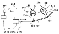
도 5는, 개방도 조정부의 변형예를 설명하기 위한 도면이다.1 is a diagram showing an overall configuration of a uni-flow scavenging two-cycle engine (gas engine).
2A is a view for explaining a structure of a fuel injection section.
FIG. 2B is a view for explaining the structure of the fuel injection section. FIG.
3 is a perspective view of the lower end side (bottom dead center side) of the fuel injection portion.
4A is a view for explaining the opening degree adjusting section.
4B is a view for explaining the opening degree adjusting section.
4C is a view for explaining the opening degree adjusting section.
5 is a diagram for explaining a modified example of the opening degree adjusting section.
이하에 첨부 도면을 참조하면서 본 개시의 적합한 실시형태에 대해 상세하게 설명한다. 이하의 실시형태에 나타내는 치수, 재료, 기타 구체적인 수치 등은 개시의 이해를 용이하게 하기 위한 예시에 불과하며, 특별히 언급하는 경우를 제외하고 본 개시를 한정하는 것은 아니다. 또, 본 명세서 및 도면에서 실질적으로 동일한 기능, 구성을 갖는 요소에 대해서는 동일한 부호를 부여함으로써 중복 설명을 생략하고, 본 개시에 직접 관계가 없는 요소는 도시를 생략한다.DETAILED DESCRIPTION OF THE PREFERRED EMBODIMENTS Hereinafter, preferred embodiments of the present invention will be described in detail with reference to the accompanying drawings. The dimensions, materials, other specific numerical values and the like shown in the following embodiments are only examples for facilitating understanding of the disclosure and are not intended to limit the present disclosure except when specifically mentioned. In the specification and drawings, elements having substantially the same function and configuration are denoted by the same reference numerals, and redundant description will be omitted. Elements not directly related to the present disclosure are not shown.
도 1은, 유니플로 소기식 2사이클 엔진(100)(가스 엔진)의 전체 구성을 나타내는 도면이다. 유니플로 소기식 2사이클 엔진(100)은, 예를 들어 선박 등에 이용된다. 구체적으로 유니플로 소기식 2사이클 엔진(100)은 실린더(110), 실린더 커버(112), 피스톤(114), 피스톤 로드(116), 소기 포트(118), 소기 탱크부(120), 소기실(122), 냉각기(124), 정류판(126), 드레인 세퍼레이터(128), 연소실(130), 배기 포트(132), 배기 밸브(134), 배기 밸브 구동 장치(136), 연료 가스 주관(主管; 138), 연료 분사 장치(140), 환상 배관(142), 연료 분사부(144)를 포함하여 구성된다.1 is a diagram showing an overall configuration of a uni-flow scavenging two-cycle engine 100 (gas engine). The uni-flow scavenging two-cycle engine 100 is used, for example, on a ship or the like. Specifically, the uni-flow scavenging two-cycle engine 100 includes a
유니플로 소기식 2사이클 엔진(100)에서는, 실린더(110)(실린더 라이너(110a)) 안을 피스톤(114)이 상하로 슬라이딩하고, 피스톤(114)의 상승 행정 및 하강 행정의 2행정 사이에 배기, 흡기, 압축, 연소, 팽창이 이루어진다. 피스톤(114)에는, 피스톤 로드(116)의 일단이 고정되어 있다. 또한, 피스톤 로드(116)의 타단에는 도시하지 않은 크로스헤드가 연결되어 있고, 크로스헤드는 피스톤(114)과 함께 왕복 이동한다. 피스톤(114)의 왕복 이동에 따라 크로스헤드가 왕복 이동하면, 그 왕복 이동에 연동하여 도시하지 않은 크랭크 샤프트가 회전한다.In the uni-flow scavenging two-cycle engine 100, the
소기 포트(118)는, 실린더(110)의 내주면으로부터 외주면까지 관통하는 구멍으로, 실린더(110)의 전체둘레에 걸쳐 복수 설치되어 있다. 그리고, 소기 포트(118)는, 피스톤(114)이 하사점으로 향하는 과정에서 개구되어 실린더(110)의 내부에 활성 가스를 유입시킨다. 이 활성 가스는 산소, 오존 등의 산화제 또는 그 혼합기(예를 들어 공기)를 포함한다.The
소기 탱크부(120)에는, 도시하지 않은 블로어에 의해 압축된 활성 가스(예를 들어 공기)가 냉각기(124)에 의해 냉각되어 봉입되어 있다. 압축 및 냉각된 활성 가스는 소기 탱크부(120) 내에 배치된 정류판(126)에 의해 정류된 후, 드레인 세퍼레이터(128)에서 수분이 제거된다.In the
소기실(122)은 소기 탱크부(120)와 연통함과 아울러, 실린더(110) 중에서 피스톤(114)의 스트로크 방향(이하, 단지 스트로크 방향이라고 부름)의 일단측(도 1 중 하측)을 둘러싸고, 압축, 냉각 및 수분 제거가 이루어진 활성 가스가 도입된다.The
여기서, 소기 탱크부(120) 및 소기실(122)은 소기 공간을 구성한다. 소기 공간은, 압축된 활성 가스가 도입되고 실린더(110) 중에서 피스톤(114)의 스트로크 방향의 일단측(도 1 중 하측)의 일부를 둘러싸는 공간이다. 여기서는 소기 공간의 일례로서 소기 탱크부(120)나 소기실(122)을 예로 들었지만, 소기 공간은, 압축된 활성 가스가 도입되어 실린더(110) 중에서 피스톤(114)의 스트로크 방향의 일단측의 일부를 둘러싸는 공간이면 소기 탱크부(120)나 소기실(122)에 한정되지 않는다.Here, the
소기 포트(118)는, 실린더(110)(실린더 라이너(110a)) 중 소기실(122)의 내측에 위치하는 부분에 설치되어 있고, 소기실(122)에 소기 포트(118)가 개구되어 있다. 피스톤(114)이 소기 포트(118)보다 하측으로 하강하였을 때, 소기 포트(118)를 통해 소기실(122)과 실린더(110) 내의 차압(差壓)에 의해 소기실(122)로부터 실린더(110) 내에 활성 가스가 흡입된다.The
연소실(130)은, 피스톤(114)이 상사점 측에 있을 때, 실린더 커버(112)(실린더 헤드)와 실린더 라이너(110a)와 피스톤(114)에 둘러싸인 공간으로서 실린더(110)의 내부에 형성된다. 실린더(110)에 흡입된 활성 가스 및 연료 가스는 피스톤(114)에 의해 연소실(130)에 도입된다.The
배기 포트(132)는, 연소실(130)의 도 1 중 상측에 형성되고, 실린더(110) 내에서 연료 가스가 연소하여 생긴 배기 가스를 배출하기 위해 개폐된다. 배기 밸브(134)는, 배기 밸브 구동 장치(136)에 의해 소정의 타이밍에 상하로 슬라이딩되어 배기 포트(132)를 개폐한다. 연료 가스의 연소 후 배기 밸브(134)가 개방되면, 소기 포트(118)로부터 유입된 활성 가스(소기)에 의해 실린더(110) 내의 배기 가스가 배기 포트(132)로부터 밀려나온다.The
연료 가스 주관(138)은, 도시하지 않은 연료 탱크에 연통함과 아울러, 연료 분사 장치(140)를 통해 환상 배관(142)과 연통하고 있다. 연료 가스 주관(138)에는 연료 탱크로부터 연료 가스가 도입되어 있고, 연료 분사 장치(140)의 밸브가 개방되면, 연료 가스 주관(138)의 연료 가스가 환상 배관(142)으로 유입된다.The fuel gas
연료 가스는, 예를 들어 LNG(액화 천연가스)를 가스화하여 생성된다. 또한, 연료 가스에는 LNG에 한정하지 않고, 예를 들어 LPG(액화 석유가스), 경유, 중유 등을 가스화하여 적용할 수도 있다.The fuel gas is produced, for example, by gasifying LNG (liquefied natural gas). Further, the fuel gas is not limited to LNG, and LPG (liquefied petroleum gas), diesel oil, heavy oil, etc. may be gasified and applied.
환상 배관(142)은, 실린더(110)의 지름 방향 외측에 소기 포트(118)보다 도 1 중 상측에 배치되어 있고, 실린더(110)의 둘레방향으로 환상으로 연장되어 실린더(110)를 둘러싸고 있다. 환상 배관(142) 중에서 소기 포트(118) 측에는 복수의 연료 분사부(144)가 고정되어 있다. 연료 분사부(144)는, 각각의 소기 포트(118)에 대해 하나씩 배치되어 스트로크 방향으로 연장되어 있다.The
연료 분사부(144)는, 실린더(110) 중에서 인접하는 소기 포트(118) 사이의 벽면에 대향되어 있고, 연료 분사부(144) 중에서 이 벽면과의 대향 부위에는 후술하는 연료 분사구가 형성되어 있다. 소기 포트(118)가 실린더(110)의 전체둘레에 걸쳐 복수 설치되어 있기 때문에, 소기 포트(118)에 맞추어 연료 분사부(144)(연료 분사구)도 실린더(110)의 둘레방향에 걸쳐 복수 설치되어 있다.The
그리고, 환상 배관(142)으로 유입된 연료 가스는, 소기 포트(118)에 흡입되는 활성 가스에 연료 분사구로부터 분사된다. 그 결과, 연료 가스는 활성 가스의 흐름에 합류하여 활성 가스와 혼합되면서 소기 포트(118)로부터 실린더(110) 내에 흡입된다.The fuel gas flowing into the
또한, 실린더 커버(112)에는 도시하지 않은 파일럿 분사 밸브가 마련되어 있고, 엔진 사이클에서의 원하는 시점에서 파일럿 분사 밸브로부터 연소실(130)에 적당량의 연료유가 분사된다. 이 연료유는 연소실(130)에 도입되어 압축된, 연료 가스와 활성 가스의 혼합기로부터의 열에 의해 기화한다. 그리고, 연료유가 기화되어 자연 착화하여 짧은 시간에 연소하여 연소실(130)의 온도가 매우 높아지고, 연소실(130)에 도입되어 압축된 연료 가스가 연소한다. 피스톤(114)은, 주로 연료 가스와 활성 가스의 혼합기의 연소에 의한 팽창압에 따라 왕복 이동한다.A pilot injection valve (not shown) is provided in the
도 2a 및 도 2b는, 연료 분사부(144)의 구조를 설명하기 위한 도면이다. 도 2a 및 도 2b에 도시된 바와 같이, 연료 분사부(144)는 내관(148)과 외관(150)으로 구성된다. 내관(148)은 환상 배관(142)과 연통하고, 환상 배관(142)으로부터 내관(148)의 본체(148a)의 내부에 연료 가스가 도입된다.Figs. 2A and 2B are views for explaining the structure of the
내관(148)은 본체(148a)의 내부와 외부를 연통시키는 내공(148b)을 가지며, 외관(150)은 본체(150a)의 내부와 외부를 연통하는 외공(150b)을 가진다. 내관(148)은, 도 2a 및 도 2b 중 하측의 하단이 폐색되어 있고 상측의 상단이 개구되어 있다. 한편, 외관(150)은 상단 및 하단이 둘 다 개구되어 있다.The
도 3은, 연료 분사부(144)의 하단부 측(하사점 측)의 사시도이다. 도 3에 도시된 바와 같이, 외관(150)은, 본체(150a)의 내부에 내관(148)을 수용하여 내관(148)과 함께 이중관을 형성한다.3 is a perspective view of the lower end side (bottom dead center side) of the
개방도 조정부(154)는, 외관(150)에 대한 내관(148)의 상대 위치를 둘레방향으로 변화시킨다. 개방도 조정부(154)는, 레버부(156)를 가지고 있다. 레버부(156)는 일단이 내관(148)의 하단부(148c)에 고정되고, 타단이 외관(150)으로부터 외관(150)의 지름 방향 외측까지 돌출되어 있다.The opening
레버부(156)의 타단에는, 커넥팅로드(158)가 회전이 자유롭게 고정되어 있다. 커넥팅로드(158)는, 실린더(110)의 둘레방향으로 인접하는 레버부(156)끼리를 연결한다. 또한, 커넥팅로드(158) 중에서 적어도 하나는 압력 구동 장치(160)의 본체(160a)로부터 돌출되는 샤프트(160b)에 연결되어 있다.At the other end of the
샤프트(160b)는, 압력 구동 장치(160)의 본체(160a)의 내부 압력에 따라 압압되고, 도 3 중 점선으로 나타내는 두 화살표 방향으로 구동한다. 그 결과, 커넥팅로드(158)가 실린더(110)의 둘레방향으로 이동하고, 커넥팅로드(158)를 통해 레버부(156)와 레버부(156)에 고정된 내관(148)이 도 3 중 실선으로 나타내는 두 화살표로 나타내는 바와 같이 내관(148)의 중심축을 회전축으로 하여 요동(회전)한다. 외관(150)은 환상 배관(142)에 고정되어 있기 때문에, 내관(148)의 요동(회전)에 따라 외관(150)에 대해 내관(148)이 둘레방향으로 상대 이동한다.The
도 4a~도 4c는, 개방도 조정부(154)를 설명하기 위한 도면이다. 도 4a에 도시된 바와 같이, 내관(148)의 내공(148b)과 외관(150)의 외공(150b)은 도 4a 중 상하 방향(스트로크 방향)의 위치가 대략 동일하다. 그 때문에, 내관(148)이 외관(150)에 대해 둘레방향으로 요동하면, 도 4c에 해칭으로 나타내는 바와 같이 내공(148b)과 외공(150b)이 서로 겹치는 부분의 면적이 변화한다.Figs. 4A to 4C are views for explaining the opening
즉, 연료 분사구(152)는 내공(148b) 및 외공(150b)으로 구성되고, 내공(148b) 및 외공(150b)이 겹침으로써 연료 분사구(152)가 형성된다. 상기와 같이, 연료 분사부(144)는, 소기 포트(118)보다 실린더(110)의 지름 방향 외측에 설치된다. 그 때문에, 연료 분사부(144)에 형성되는 연료 분사구(152)도, 소기 포트(118)보다 실린더(110)의 지름 방향 외측(실린더(110)의 외측)에 설치된다.That is, the
개방도 조정부(154)는, 외관(150)에 대한 내관(148)의 상대 위치를 둘레방향으로 변화시켜, 내공(148b)과 외공(150b)이 겹치는 부분의 면적을 크게 함으로써 연료 분사구(152)를 크게 하고, 내공(148b)과 외공(150b)이 겹치는 부분의 면적을 작게 함으로써 연료 분사구(152)를 작게 한다. 이와 같이, 연료 분사구(152)의 개방도는 내공(148b)과 외공(150b)의 겹침 정도에 의해 가변이 된다.The opening
또한, 개방도 조정부(154)는 수압부(受壓部; 162)를 가지고 있다. 수압부(162)는, 실린더(110)를 둘러싸는 소기 공간(소기 탱크부(120), 소기실(122)) 중에서 연료 분사구(152)보다 소기 포트(118)로부터 떨어진 위치에서 소기압(Psc)을 받는다.Further, the opening
구체적으로 수압부(162)는 배관으로 구성되어 있고, 일단이 소기 공간으로 개구됨과 아울러, 도 4b에 도시된 바와 같이 타단이 압력 구동 장치(160)의 본체(160a)의 내부에 연통하고 있다. 여기서, 수압부(162)의 일단은, 소기 공간 중에서 연료 분사구(152)보다 소기 포트(118)로부터 떨어지고, 연료 분사구(152)보다 피스톤(114)에 의한 소기 포트(118)의 개폐에 의한 압력 변동을 받기 어려운 위치에 배치된다. 그리고, 수압부(162)의 내압은 대략 정상적인 소기 공간의 소기압(Psc)과 동일해진다.Specifically, the
본체(160a)의 내부는 중공(中空)이며 구동 피스톤(160c)이 수용되어 있다. 구동 피스톤(160c)은, 본체(160a)의 내부를 제1 공기실(160d)과 제2 공기실(160e)로 구획한다. 제2 공기실(160e)에는 코일 스프링(160f)이 수용되어 있고, 구동 피스톤(160c)을 제1 공기실(160d) 측으로 압압한다.The inside of the
제1 공기실(160d)에는 수압부(162)가 연통하고 있다. 또한, 제2 공기실(160e)은, 예를 들어 유니플로 소기식 2사이클 엔진(100)의 외부에 연통하고 있고, 그 내압은 대기압(Patm)으로 되어 있다.A
그 때문에, 소기압(Psc)이 높아지면, 제1 공기실(160d)의 내부 압력에 따라 구동 피스톤(160c)이 제2 공기실(160e) 측으로 이동한다. 구동 피스톤(160c)에는 상기 샤프트(160b)가 고정되어 있기 때문에, 구동 피스톤(160c)의 움직임에 연동하여 샤프트(160b)가 이동한다.Therefore, when the small air pressure Psc becomes high, the
그 결과, 상기와 같이 외관(150)에 대해 내관(148)이 둘레방향으로 상대 이동하고, 연료 분사구(152)의 개방도가 변화한다. 이와 같이, 개방도 조정부(154)는, 수압부(162)가 받는 소기압(Psc)과 대기압(Patm)의 차압 변화에 의해 연료 분사구(152)의 개방도를 바꾼다. 예를 들어, 개방도 조정부(154)는, 소기압(Psc)이 상승하면 연료 분사구(152)의 개방도를 크게 하고, 소기압(Psc)이 하강하면 연료 분사구(152)의 개방도를 작게 한다.As a result, as described above, the
예를 들어, 소기압(Psc)이 높아져 연료 가스의 분사량을 늘릴 필요가 있을 때, 연료 분사구(152)의 개구 면적이 너무 작으면 연료 가스가 분사되기 어렵다. 그 때문에, 연료 분사 장치(140)의 밸브 개방 기간을 길게 하여 대응하고자 해도 소기 포트(118)가 개구되어 있는 기간에는 한계가 있어, 개방 기간으로서 설정 가능한 길이에 한계가 있다. 또한, 연료 가스의 압력을 상승시키는 데에도 펌프 성능의 한계가 있다.For example, when it is necessary to increase the injection amount of the fuel gas due to the increase of the small air pressure Psc, if the opening area of the fuel injection opening 152 is too small, the fuel gas is difficult to be injected. Therefore, there is a limit to the period in which the
한편, 연료 분사구(152)의 개구 면적을 미리 크게 설계하면, 소기압(Psc)이 낮아져 연료 가스의 분사량을 줄일 필요가 있을 때에도 연료 분사구(152)로부터 연료 가스가 용이하게 분사된다. 그 때문에, 연료 분사 장치(140)의 밸브 개방 기간을 짧게 하여 대응하면, 단기간의 분사로 소기의 분사량에 도달하기 때문에 연료 가스가 활성 가스 중에서 덩어리 형상이 되어 혼합이 진행되기 어렵다. 또한, 연료 가스의 압력을 저하시켜 대응하면, 연료 분사부(144)의 내관(148)의 내부에 연료 가스가 체류하기 쉬워지고 역시 활성 가스와의 혼합이 진행되기 어렵다.On the other hand, when the opening area of the fuel injection opening 152 is designed to be large in advance, the fuel gas is easily injected from the fuel injection opening 152 even when the small air pressure Psc is lowered and the fuel gas injection amount needs to be reduced. Therefore, if the valve opening period of the
그래서, 본 실시형태에서는, 상술한 바와 같이 개방도 조정부(154)가 연료 분사구(152)의 개방도를 소기압(Psc)에 따라 변화시킴으로써, 연료 가스를 적절한 압력으로 분사하여 활성 가스와의 혼합을 촉진하는 것이 가능해진다.Thus, in the present embodiment, as described above, the opening
또한, 개방도 조정부(154)는, 수압부(162)가 받는 소기압(Psc)과 대기압(Patm)의 차압 변화에 따라 본체(160a)의 내부에 수용된 구동 피스톤(160c)을 움직이고, 구동 피스톤(160c)의 움직임에 연동하여 샤프트(160b)를 이동시킴으로써 수용 연료 분사구(152)의 개방도를 바꾸고 있다. 그 때문에, 전기적인 기구에 비해 고장나기 어렵고 내구성을 향상시키는 것이 가능해진다.The opening
또한, 연료 분사부(144)를 내관(148)과 외관(150)으로 구성하고, 연료 분사구(152)의 개방도가 내공(148b)과 외공(150b)의 겹침에 따라 가변이 된다. 그 때문에, 연료 분사구(152)의 개방도가 가변인 연료 분사부(144)를 간이한 구성으로 실현할 수 있다.The
또한, 내관(148)과 외관(150)이 둘레방향으로 상대 회전하여 연료 분사구(152)의 개방도가 변경된다. 그 때문에, 연료 분사구(152)의 스트로크 방향의 위치를 거의 바꾸지 않고 개방도의 변경이 가능해진다.Further, the
또한, 유니플로 소기식 2사이클 엔진(100)이 정지 중에 소기압(Psc)이 대기압(Patm) 정도가 되면, 구동 피스톤(160c)은 코일 스프링(160f)에 압압되어 제1 공기실(160d) 측으로 이동한다. 이 때, 내공(148b)과 외공(150b)이 둘레방향으로 떨어져(어긋나) 서로 겹치지 않도록 설계되어 있고, 연료 분사구(152)는 닫힌다. 그 때문에, 연료 분사부(144)의 내부의 연료 가스는 소기실(122)로 누출되기 어려워지고 안전성이 향상된다.When the small air pressure Psc reaches about the atmospheric pressure (Patm) during the stop of the uni-flow scavenging two-cycle engine 100, the
또한, 제1 공기실(160d)에는 외기에 연통하는 배관(164a)이 접속되어 있고, 배관(164a)에는 긴급 차단 밸브(164b)가 설치되어 있다. 긴급 차단 밸브(164b)는 예를 들어 전자(電磁) 밸브로 구성되고, 통상시 긴급 차단 밸브(164b)는 폐쇄되어 있다. 유니플로 소기식 2사이클 엔진(100)을 긴급 정지해야 할 때는, 긴급 차단 밸브(164b)가 개방된다. 그 결과, 제1 공기실(160d) 내의 압력이 저하되고, 코일 스프링(160f)에 의해 구동 피스톤(160c)이 제1 공기실(160d) 측으로 이동한다. 이렇게 하여 연료 분사구(152)를 신속히 닫고 연료 분사구(152)로부터 연료 가스의 분사를 정지할 수 있어 안전성이 향상된다.The
도 5는, 개방도 조정부의 변형예를 설명하기 위한 도면이다. 상술한 실시형태에서는, 개방도 조정부(154)는 소기압(Psc)에 따라 연료 분사구(152)의 개방도를 기계적으로 바꾸는 경우에 대해 설명하였지만, 변형예에서는 개방도 조정부(254)는 소기압(Psc)과 함께 변동하는 파라미터의 값에 따라 연료 분사구(152)의 개방도를 전기적으로 바꾼다.5 is a diagram for explaining a modified example of the opening degree adjusting section. Although the opening
구체적으로는, 유니플로 소기식 2사이클 엔진(100)은 데이터 취득부(266)를 가지고 있다. 데이터 취득부(266)는, 예를 들어 센서로 구성되고, 수압부(162)와 마찬가지로 소기 공간 중에서 연료 분사구(152)보다 소기 포트(118)로부터 떨어진 위치에 배치되어, 대략 정상적인 소기 공간의 소기압(Psc)을 취득(검지)하여 전기 신호로 치환한다. 즉, 도 5의 예에서는, 파라미터로서 예를 들어 소기압(Psc)이 치환된 전기 신호가 적용되어 있다.Specifically, the uni-flow scavenging two-cycle engine 100 has a
개방도 조정부(254)는, 액추에이터(254a)와 제어부(254b)를 포함하여 구성된다. 제어부(254b)는, 데이터 취득부(266)로부터 전기 신호를 수신하고, 수신한 전기 신호가 나타내는 값에 따라 액추에이터(254a)를 제어한다.The opening
액추에이터(254a)에 장착된 샤프트(254c)는, 액추에이터(254a)에 의해 도 5 중 점선으로 나타내는 양 화살표 방향으로 이동한다. 그 결과, 상술한 실시형태와 마찬가지로 샤프트(254c)에 연결된 커넥팅로드(158)와 레버부(156)를 통해 내관(148)이 외관(150)에 대해 둘레방향으로 상대 이동한다.The
이와 같이, 개방도 조정부(254)가 액추에이터(254a)에 의해 내관(148)을 움직임으로써, 상술한 실시형태와 마찬가지로 연료 가스를 적절한 압력으로 분사하여 활성 가스와의 혼합을 촉진하는 것이 가능해진다. 또한, 액추에이터(254a)의 동작은 전기적인 제어이기 때문에, 내관(148)의 둘레방향의 이동량이 용이하게 설정 가능해진다.As described above, by opening the
이상, 첨부 도면을 참조하면서 본 개시의 적합한 실시형태에 대해 설명하였지만, 본 개시는 이러한 실시형태에 한정되지 않는 것은 물론이다. 당업자라면 청구범위에 기재된 범주에서 각종 변경예 또는 수정예를 생각해 낼 수 있는 것은 명백하고, 이들에 대해서도 당연히 본 개시의 기술적 범위에 속한다고 이해된다.While the preferred embodiments of the present disclosure have been described with reference to the accompanying drawings, it is needless to say that the present disclosure is not limited to these embodiments. It will be understood by those skilled in the art that various changes in form and details may be made therein without departing from the spirit and scope of the invention as defined by the appended claims.
예를 들어, 상술한 변형예에서는, 소기압(Psc)과 함께 변동하는 파라미터로서 센서가 소기압(Psc)을 검지하여 치환한 전기 신호를 예로 들어 설명하였지만, 파라미터는 소기압(Psc)과 함께 변동하는 값이면 되고, 예를 들어 엔진 회전수, 엔진 로드, 엔진 토크, 블로어의 풍량 등이어도 된다.For example, in the above-described modified example, the electric signal obtained by detecting and replacing the small pressure Psc as a parameter that fluctuates with the small gap pressure Psc has been described as an example, but the parameter is not limited to the small gap pressure Psc And may be, for example, the engine speed, the engine load, the engine torque, the air flow rate of the blower, or the like.
또한, 상술한 실시형태 및 변형예에서는, 개방도 조정부(154, 254)는 소기압(Psc)이 상승하면 연료 분사구(152)의 개방도를 크게 하고, 소기압(Psc)이 하강하면 연료 분사구(152)의 개방도를 작게 하는 경우에 대해 설명하였다. 그러나, 개방도 조정부(154, 254)는, 소기압(Psc)과 함께 변동하는 파라미터의 값 혹은 소기압(Psc)에 따라 연료 분사구(152)의 개방도를 적어도 바꾸면 된다.In the embodiment and the modification described above, the opening
또한, 상술한 실시형태에서는, 수압부(162)는 소기 공간 중에서 연료 분사구(152)보다 소기 포트(118)로부터 떨어진 위치에서 소기압(Psc)을 받는 경우에 대해 설명하였다. 그러나, 수압부(162)는 소기압(Psc)을 받기만 하면 어디에 배치되어도 된다. 단, 수압부(162)가 소기 공간 중에서 연료 분사구(152)보다 소기 포트(118)로부터 떨어진 위치에서 소기압(Psc)을 받음으로써, 소기 포트(118)의 개폐에 의한 활성 가스 흐름의 영향을 받기 어려워서, 연료 분사구(152)의 개방도를 적절한 크기로 안정시키는 것이 가능해진다.In the above-described embodiment, the
또한, 상술한 실시형태 및 변형예에서는, 연료 분사부(144)가 내관(148)과 외관(150)의 이중관으로 구성되고, 연료 분사구(152)가 내관(148)의 내공(148b)과 외관(150)의 외공(150b)으로 구성되는 경우에 대해 설명하였다. 그러나, 내관(148)과 외관(150)을 설치하지 않고 다른 기구에 의해 연료 분사구(152)의 개방도를 가변으로 해도 된다.The
또한, 상술한 실시형태 및 변형예에서는, 연료 분사부(144)는 내관(148)과 외관(150)이 둘레방향으로 상대 회전하여 연료 분사구(152)의 개방도가 변경되는 경우에 대해 설명하였다. 그러나, 내관(148)과 외관(150)이 스트로크 방향으로 상대 이동하여 연료 분사구(152)의 개방도가 변경되어도 된다.In the above-described embodiment and modified examples, the
또한, 상술한 실시형태 및 변형예에서는, 내공(148b)과 외공(150b)이 동일한 원형인 경우에 대해 설명하였지만, 내공(148b)과 외공(150b) 중 한쪽 또는 양쪽을 다른 형상으로 해도 된다.Although the inner and
본 개시는 듀얼 퓨얼형 가스 엔진에 이용할 수 있다.The present disclosure is applicable to dual-fuels gas engines.
100 유니플로 소기식 2사이클 엔진(가스 엔진)
110 실린더
118 소기 포트
120 소기 탱크부(소기 공간)
122 소기실(소기 공간)
132 배기 포트
144 연료 분사부
152 연료 분사구
148 내관
148b 내공
150 외관
150b 외공
154 개방도 조정부
162 수압부
254 개방도 조정부
254a 액추에이터
266 데이터 취득부100 Uni-flow scavenging 2 cycle engine (gas engine)
110 cylinders
118 Sewer port
120 Waste tanks (scavenging space)
122 Small room (small space)
132 Exhaust port
144 fuel injection part
152 fuel injection nozzle
148 inside
148b
150 Appearance
150b
154 opening degree adjustment section
162 Hydraulic section
254 opening degree adjusting section
254a actuator
266 Data acquisition unit
Claims (8)
상기 실린더의 외측에 위치하는 연료 분사구를 가지며, 상기 소기 포트로부터 상기 실린더에 흡입되는 상기 활성 가스에 상기 연료 분사구로부터 연료 가스를 분사하는 연료 분사부와,
소기압과 함께 변동하는 파라미터의 값 혹은 상기 소기압에 따라, 상기 연료 분사구의 개방도를 기계적 또는 전기적으로 바꾸는 개방도 조정부를 구비하는 가스 엔진.A gas engine in which an active gas flows into a cylinder from a scavenge port and a fuel gas mixed with the active gas is burned,
A fuel injection portion having a fuel injection port located outside the cylinder and injecting fuel gas from the fuel injection port into the active gas sucked into the cylinder from the scavenging port;
And an opening degree adjusting section for mechanically or electrically changing the opening degree of the fuel injection opening in accordance with the value of the parameter varying with the small air pressure or the small air pressure.
상기 개방도 조정부는, 상기 소기압이 상승하면 상기 연료 분사구의 개방도를 크게 하고, 상기 소기압이 하강하면 상기 연료 분사구의 개방도를 작게 하는 가스 엔진.The method according to claim 1,
Wherein the opening degree adjusting section increases the opening degree of the fuel injection opening when the small air pressure rises and reduces the opening degree of the fuel injection opening when the small air pressure falls.
상기 실린더의 일부를 둘러싸고, 압축된 활성 가스가 도입되는 소기 공간 중에서 상기 연료 분사구보다 상기 소기 포트로부터 떨어진 위치에서 소기압을 받는 수압부(受壓部)를 더 구비하고,
상기 개방도 조정부는, 상기 수압부가 받는 소기압과 대기압의 차압(差壓) 변화에 따라 상기 연료 분사구의 개방도를 바꾸는 가스 엔진.The method according to claim 1,
Further comprising a pressure receiving portion surrounding a part of the cylinder and receiving a small pressure at a position spaced apart from the scavenge opening of the fuel injection opening among the scavenged space into which the compressed active gas is introduced,
Wherein the opening degree adjusting section changes the opening degree of the fuel injection opening in accordance with a differential pressure difference between the atmospheric pressure and the atmospheric pressure.
상기 실린더의 일부를 둘러싸고, 압축된 활성 가스가 도입되는 소기 공간 중에서 상기 연료 분사구보다 상기 소기 포트로부터 떨어진 위치에서 소기압을 받는 수압부를 더 구비하고,
상기 개방도 조정부는, 상기 수압부가 받는 소기압과 대기압의 차압 변화에 따라 상기 연료 분사구의 개방도를 바꾸는 가스 엔진.The method of claim 2,
Further comprising a pressure receiving portion surrounding a part of the cylinder and receiving a small pressure at a position away from the scavenging port from the fuel injection opening among the scavenging spaces into which the compressed active gas is introduced,
Wherein the opening degree adjusting section changes the opening degree of the fuel injection opening in accordance with a pressure difference between the atmospheric pressure and the atmospheric pressure.
상기 파라미터의 값을 취득하는 데이터 취득부를 더 구비하고,
상기 개방도 조정부는, 상기 데이터 취득부가 취득한 상기 파라미터의 값에 따라 상기 연료 분사구의 개방도를 바꾸는 액추에이터를 갖는 가스 엔진.The method according to claim 1,
And a data acquiring unit that acquires the value of the parameter,
And the opening degree adjustment section has an actuator that changes the opening degree of the fuel injection opening in accordance with the value of the parameter acquired by the data acquisition section.
상기 파라미터의 값을 취득하는 데이터 취득부를 더 구비하고,
상기 개방도 조정부는, 상기 데이터 취득부가 취득한 상기 파라미터의 값에 따라 상기 연료 분사구의 개방도를 바꾸는 액추에이터를 갖는 가스 엔진.The method of claim 2,
And a data acquiring unit that acquires the value of the parameter,
And the opening degree adjustment section has an actuator that changes the opening degree of the fuel injection opening in accordance with the value of the parameter acquired by the data acquisition section.
상기 연료 분사부는,
내부와 외부를 관통하는 내공이 형성되어, 상기 내부에 연료 가스가 도입되는 내관과,
내부와 외부를 관통하는 외공이 형성되어, 상기 내부에 상기 내관을 수용하여 상기 내관과 함께 이중관을 형성하는 외관을 구비하고,
상기 연료 분사구는 상기 내공 및 상기 외공으로 구성되고, 상기 내공과 상기 외공의 겹침에 의해 개방도가 가변이 되는 가스 엔진.The method according to any one of claims 1 to 6,
Wherein the fuel injection unit includes:
An inner pipe through which the fuel gas is introduced,
And an outer tube having an outer tube formed therein and passing through the inner tube and the outer tube to receive the inner tube and form a double tube together with the inner tube,
Wherein the fuel injection port is composed of the inner hole and the outer hole, and the opening degree is variable by overlapping the inner hole and the outer hole.
상기 내관과 상기 외관이 둘레방향으로 상대 회전하여 상기 연료 분사구의 개방도가 변경되는 가스 엔진.The method of claim 7,
Wherein the inner tube and the outer tube relatively rotate in the circumferential direction to change the opening degree of the fuel injection port.
Applications Claiming Priority (3)
| Application Number | Priority Date | Filing Date | Title |
|---|---|---|---|
| JP2015233168 | 2015-11-30 | ||
| JPJP-P-2015-233168 | 2015-11-30 | ||
| PCT/JP2016/084989 WO2017094616A1 (en) | 2015-11-30 | 2016-11-25 | Gas engine |
Publications (2)
| Publication Number | Publication Date |
|---|---|
| KR20180054792A true KR20180054792A (en) | 2018-05-24 |
| KR102074477B1 KR102074477B1 (en) | 2020-02-06 |
Family
ID=58796776
Family Applications (1)
| Application Number | Title | Priority Date | Filing Date |
|---|---|---|---|
| KR1020187011045A Active KR102074477B1 (en) | 2015-11-30 | 2016-11-25 | Gas engine |
Country Status (6)
| Country | Link |
|---|---|
| EP (1) | EP3385530B1 (en) |
| JP (1) | JP6521095B2 (en) |
| KR (1) | KR102074477B1 (en) |
| CN (1) | CN108291500B (en) |
| DK (1) | DK3385530T3 (en) |
| WO (1) | WO2017094616A1 (en) |
Families Citing this family (1)
| Publication number | Priority date | Publication date | Assignee | Title |
|---|---|---|---|---|
| CN112284621B (en) * | 2020-11-24 | 2025-08-01 | 中船动力有限公司 | Dual-fuel engine jet assembly sealing detection device and detection method |
Citations (4)
| Publication number | Priority date | Publication date | Assignee | Title |
|---|---|---|---|---|
| JPH06323156A (en) * | 1993-05-18 | 1994-11-22 | Isuzu Motors Ltd | Control device for turbocharger provided with dynamo-electric machine |
| JP2005163683A (en) * | 2003-12-03 | 2005-06-23 | Mitsubishi Heavy Ind Ltd | Gas engine with gas fuel supply device |
| JP3908855B2 (en) | 1997-04-29 | 2007-04-25 | マーン・ベー・オグ・ドバルドヴェー・ディーゼール・アクティーゼルスカブ | Method of operating a diesel turbocharged dual fuel internal combustion engine |
| WO2014181864A1 (en) * | 2013-05-10 | 2014-11-13 | 株式会社Ihi | Uniflow scavenging 2-cycle engine |
Family Cites Families (10)
| Publication number | Priority date | Publication date | Assignee | Title |
|---|---|---|---|---|
| NL9002862A (en) * | 1990-12-21 | 1992-07-16 | Necam Bv | DEVICE FOR INJECTING A GASEOUS FUEL IN A COMBUSTION ENGINE, METHOD AND PRESSURE REGULATOR THEREFOR. |
| US5546919A (en) * | 1993-08-31 | 1996-08-20 | Yamaha Hatsudoki Kabushiki Kaisha | Operating arrangement for gaseous fueled engine |
| JP5618803B2 (en) * | 2010-12-09 | 2014-11-05 | 日立造船株式会社 | 2-stroke engine and 4-stroke engine |
| JP5811538B2 (en) * | 2011-01-24 | 2015-11-11 | 株式会社Ihi | 2-cycle engine |
| CN103732904B (en) * | 2011-06-14 | 2016-08-24 | Wsc斯利有限公司 | The method of postcritical diesel combustion |
| JP5983196B2 (en) * | 2012-08-31 | 2016-08-31 | 株式会社Ihi | Uniflow scavenging 2-cycle engine |
| JP5480961B1 (en) * | 2012-12-14 | 2014-04-23 | 川崎重工業株式会社 | Gas engine drive system and ship |
| US9181883B2 (en) * | 2013-01-18 | 2015-11-10 | Nagesh S. Mavinahally | Four cycle engine carburetors |
| US9316558B2 (en) * | 2013-06-04 | 2016-04-19 | GM Global Technology Operations LLC | System and method to diagnose fuel system pressure sensor |
| WO2015098970A1 (en) * | 2013-12-24 | 2015-07-02 | 株式会社Ihi | Uniflow scavenging 2-cycle engine |
-
2016
- 2016-11-25 EP EP16870553.1A patent/EP3385530B1/en active Active
- 2016-11-25 KR KR1020187011045A patent/KR102074477B1/en active Active
- 2016-11-25 DK DK16870553.1T patent/DK3385530T3/en active
- 2016-11-25 JP JP2017553819A patent/JP6521095B2/en active Active
- 2016-11-25 CN CN201680069389.2A patent/CN108291500B/en active Active
- 2016-11-25 WO PCT/JP2016/084989 patent/WO2017094616A1/en not_active Ceased
Patent Citations (5)
| Publication number | Priority date | Publication date | Assignee | Title |
|---|---|---|---|---|
| JPH06323156A (en) * | 1993-05-18 | 1994-11-22 | Isuzu Motors Ltd | Control device for turbocharger provided with dynamo-electric machine |
| JP3908855B2 (en) | 1997-04-29 | 2007-04-25 | マーン・ベー・オグ・ドバルドヴェー・ディーゼール・アクティーゼルスカブ | Method of operating a diesel turbocharged dual fuel internal combustion engine |
| JP2005163683A (en) * | 2003-12-03 | 2005-06-23 | Mitsubishi Heavy Ind Ltd | Gas engine with gas fuel supply device |
| WO2014181864A1 (en) * | 2013-05-10 | 2014-11-13 | 株式会社Ihi | Uniflow scavenging 2-cycle engine |
| KR20150119296A (en) * | 2013-05-10 | 2015-10-23 | 가부시키가이샤 아이에이치아이 | Uniflow scavenging 2-cycle engine |
Also Published As
| Publication number | Publication date |
|---|---|
| CN108291500B (en) | 2021-01-01 |
| JP6521095B2 (en) | 2019-05-29 |
| CN108291500A (en) | 2018-07-17 |
| EP3385530B1 (en) | 2021-09-08 |
| EP3385530A4 (en) | 2019-06-26 |
| DK3385530T3 (en) | 2021-10-18 |
| WO2017094616A1 (en) | 2017-06-08 |
| KR102074477B1 (en) | 2020-02-06 |
| EP3385530A1 (en) | 2018-10-10 |
| JPWO2017094616A1 (en) | 2018-07-12 |
Similar Documents
| Publication | Publication Date | Title |
|---|---|---|
| KR101411395B1 (en) | Two-stroke engine | |
| JP5587091B2 (en) | 2-stroke gas engine | |
| JP5452730B2 (en) | 2-stroke engine | |
| EP2891780B1 (en) | Uniflow scavenging two-cycle engine | |
| JP6137340B2 (en) | Crosshead engine | |
| KR101982658B1 (en) | Uniflow-scavenged two-cycle engine | |
| CN111836955A (en) | marine engine | |
| KR20180054792A (en) | Gas engine | |
| JP2014101884A (en) | Two-stroke gas engine | |
| KR20190045793A (en) | Engine for Ship | |
| KR102217236B1 (en) | Uniflow scavenging two-cycle engine | |
| KR20150119287A (en) | Uniflow scavenging 2-cycle engine | |
| JP6455312B2 (en) | Uniflow scavenging 2-cycle engine | |
| JP6432285B2 (en) | Uniflow scavenging 2-cycle engine | |
| KR20200044958A (en) | Variable compression system and engine system | |
| JP2019124133A (en) | engine |
Legal Events
| Date | Code | Title | Description |
|---|---|---|---|
| A201 | Request for examination | ||
| PA0105 | International application |
Patent event date: 20180419 Patent event code: PA01051R01D Comment text: International Patent Application |
|
| PA0201 | Request for examination | ||
| PG1501 | Laying open of application | ||
| E902 | Notification of reason for refusal | ||
| PE0902 | Notice of grounds for rejection |
Comment text: Notification of reason for refusal Patent event date: 20190222 Patent event code: PE09021S01D |
|
| E902 | Notification of reason for refusal | ||
| PE0902 | Notice of grounds for rejection |
Comment text: Notification of reason for refusal Patent event date: 20190708 Patent event code: PE09021S01D |
|
| E701 | Decision to grant or registration of patent right | ||
| PE0701 | Decision of registration |
Patent event code: PE07011S01D Comment text: Decision to Grant Registration Patent event date: 20200107 |
|
| GRNT | Written decision to grant | ||
| PR0701 | Registration of establishment |
Comment text: Registration of Establishment Patent event date: 20200131 Patent event code: PR07011E01D |
|
| PR1002 | Payment of registration fee |
Payment date: 20200203 End annual number: 3 Start annual number: 1 |
|
| PG1601 | Publication of registration | ||
| PR1001 | Payment of annual fee |
Payment date: 20231218 Start annual number: 5 End annual number: 5 |
|
| PR1001 | Payment of annual fee |
Payment date: 20241216 Start annual number: 6 End annual number: 6 |