KR20180093473A - Hermetic compressor - Google Patents
Hermetic compressor Download PDFInfo
- Publication number
- KR20180093473A KR20180093473A KR1020170019620A KR20170019620A KR20180093473A KR 20180093473 A KR20180093473 A KR 20180093473A KR 1020170019620 A KR1020170019620 A KR 1020170019620A KR 20170019620 A KR20170019620 A KR 20170019620A KR 20180093473 A KR20180093473 A KR 20180093473A
- Authority
- KR
- South Korea
- Prior art keywords
- housing
- refrigerant
- liquid refrigerant
- casing
- inlet
- Prior art date
- Legal status (The legal status is an assumption and is not a legal conclusion. Google has not performed a legal analysis and makes no representation as to the accuracy of the status listed.)
- Withdrawn
Links
Images



Classifications
-
- F—MECHANICAL ENGINEERING; LIGHTING; HEATING; WEAPONS; BLASTING
- F04—POSITIVE - DISPLACEMENT MACHINES FOR LIQUIDS; PUMPS FOR LIQUIDS OR ELASTIC FLUIDS
- F04C—ROTARY-PISTON, OR OSCILLATING-PISTON, POSITIVE-DISPLACEMENT MACHINES FOR LIQUIDS; ROTARY-PISTON, OR OSCILLATING-PISTON, POSITIVE-DISPLACEMENT PUMPS
- F04C29/00—Component parts, details or accessories of pumps or pumping installations, not provided for in groups F04C18/00 - F04C28/00
- F04C29/0092—Removing solid or liquid contaminants from the gas under pumping, e.g. by filtering or deposition; Purging; Scrubbing; Cleaning
-
- F—MECHANICAL ENGINEERING; LIGHTING; HEATING; WEAPONS; BLASTING
- F04—POSITIVE - DISPLACEMENT MACHINES FOR LIQUIDS; PUMPS FOR LIQUIDS OR ELASTIC FLUIDS
- F04B—POSITIVE-DISPLACEMENT MACHINES FOR LIQUIDS; PUMPS
- F04B39/00—Component parts, details, or accessories, of pumps or pumping systems specially adapted for elastic fluids, not otherwise provided for in, or of interest apart from, groups F04B25/00 - F04B37/00
- F04B39/16—Filtration; Moisture separation
-
- F—MECHANICAL ENGINEERING; LIGHTING; HEATING; WEAPONS; BLASTING
- F04—POSITIVE - DISPLACEMENT MACHINES FOR LIQUIDS; PUMPS FOR LIQUIDS OR ELASTIC FLUIDS
- F04C—ROTARY-PISTON, OR OSCILLATING-PISTON, POSITIVE-DISPLACEMENT MACHINES FOR LIQUIDS; ROTARY-PISTON, OR OSCILLATING-PISTON, POSITIVE-DISPLACEMENT PUMPS
- F04C18/00—Rotary-piston pumps specially adapted for elastic fluids
- F04C18/02—Rotary-piston pumps specially adapted for elastic fluids of arcuate-engagement type, i.e. with circular translatory movement of co-operating members, each member having the same number of teeth or tooth-equivalents
Landscapes
- Engineering & Computer Science (AREA)
- Mechanical Engineering (AREA)
- General Engineering & Computer Science (AREA)
- Applications Or Details Of Rotary Compressors (AREA)
- Compressor (AREA)
Abstract
본 발명에 따른 밀폐형 압축기는, 케이싱; 상기 케이싱 내부에서 회전되는 회전축을 구동시키는 구동 유닛; 상기 케이싱에 고정되는 실린더와, 상기 회전축과 연결되어 회전되는 롤러를 구비하는 압축 유닛; 및 흡입구로 액체 상태의 냉매가 흡입되는 것을 제한하는 어큐뮬레이터를 포함하며, 상기 어큐뮬레이터는, 유입구를 구비하는 하우징; 일 단은 상기 하우징에 삽입되어 상기 유입구와 기설정된 간격으로 이격 배치되는 유출구를 형성하고 타 단은 상기 흡입구에 연결되는 연결 튜브; 및 상기 유입구에서 연장 형성되고, 상기 하우징의 내주면을 따라 선회하는 냉매 흐름을 형성하도록 이루어지는 액냉매 분리 부재를 구비한다. 이에 의하면, 액냉매가 기냉매로부터 원심 분리되어, 케이싱 내부로 흡입되는 것이 제한될 수 있다.A hermetic compressor according to the present invention includes: a casing; A driving unit for driving a rotating shaft rotated in the casing; A cylinder fixed to the casing, and a roller connected to the rotation shaft and rotated; And an accumulator for limiting suction of liquid refrigerant into the suction port, wherein the accumulator comprises: a housing having an inlet; One end of which is inserted into the housing and forms an outlet which is spaced apart from the inlet by a predetermined distance, and the other end is connected to the inlet; And a liquid refrigerant separating member which is formed to extend from the inlet and forms a refrigerant flow which swirls along the inner circumferential surface of the housing. According to this, the liquid refrigerant can be centrifugally separated from the gas refrigerant and sucked into the casing.
Description
본 발명은 밀폐형 압축기에 관한 것으로, 특히 냉매가 상변화하며 순환하는 냉동 사이클을 구성하는 로터리 압축기에 관한 것이다.BACKGROUND OF THE INVENTION 1. Field of the Invention The present invention relates to a hermetic compressor, and more particularly, to a rotary compressor constituting a refrigeration cycle in which refrigerant is phase-changed and circulated.
일반적으로 압축기는 냉매를 압축하는 방식에 따라 회전식과 왕복동식으로 구분할 수 있다. 회전식 압축기는 피스톤이 실린더에서 회전 또는 선회운동을 하면서 압축공간의 체적을 가변시키는 방식이고, 왕복동식 압축기는 피스톤이 실린더에서 왕복운동을 하면서 압축공간의 체적을 가변시키는 방식이다. 회전식 압축기로는 전동부의 회전력을 이용하여 피스톤이 회전을 하면서 냉매를 압축하는 로터리 압축기가 알려져 있다.Generally, a compressor can be divided into a rotary type and a reciprocating type according to a method of compressing a refrigerant. The rotary compressor is a method of varying the volume of the compression space while the piston is rotating or revolving in the cylinder, and the reciprocating compressor is a method of varying the volume of the compression space while the piston reciprocates in the cylinder. BACKGROUND ART As a rotary compressor, there is known a rotary compressor which compresses a refrigerant while rotating a piston using a rotary force of a driving portion.
로터리 압축기는 롤러와 베인이 접촉되어, 그 베인을 중심으로 실린더의 압축공간이 흡입실과 토출실로 구분되는 압축기이다. 일반적인 로터리 압축기는 롤러가 선회운동을 하면서 실린더에 삽입 장착된 베인이 직선운동을 하게 되고, 이에 따라 흡입실과 토출실은 체적(용적)이 가변되는 압축실을 형성하여 냉매를 흡입, 압축, 토출하게 된다.A rotary compressor is a compressor in which a roller and a vane are brought into contact with each other, and a compression space of the cylinder is divided into a suction chamber and a discharge chamber around the vane. In a general rotary compressor, a vane in which a roller is pivotally moved causes a vane to be linearly moved, so that the suction chamber and the discharge chamber form a compression chamber having a variable volume (volume), thereby sucking, compressing, and discharging the refrigerant .
또한, 일반적으로 밀폐형 압축기는 밀폐된 케이싱의 내부 공간에 구동력을 발생시키는 구동모터 및 그 구동모터의 구동력을 전달받아 유체를 압축하는 압축부가 함께 구비되어 있는 방식을 말한다.Generally, a hermetic compressor refers to a system in which a driving motor for generating a driving force in an internal space of a sealed casing and a compression unit for receiving a driving force of the driving motor and compressing the fluid are provided together.
로터리 압축기 등의 밀폐형 압축기가 냉동 사이클을 구성하여 냉매를 압축하도록 이루어지는 경우, 액체 상태의 냉매(액냉매)의 유입이 문제될 수 있다. 특히,증발기를 통과한 냉매의 과열도가 크지 않은 상황에서, 냉동 사이클의 운전 조건이 다양하게 가변되는 경우 액냉매가 유입될 수 있는 가능성은 더욱 높아진다.When a hermetic compressor such as a rotary compressor constitutes a refrigeration cycle to compress the refrigerant, the inflow of the refrigerant in the liquid state (liquid refrigerant) may be a problem. Particularly, in a situation where the degree of superheat of the refrigerant passing through the evaporator is not large, the possibility that the liquid refrigerant can flow in the case where the operating condition of the refrigeration cycle is varied variously becomes higher.
이러한 경우, 밀폐형 압축기는 액체를 압축하도록 작동되므로 동력 입력이 상승되어 효율이 저하된다. 또한, 액체 입자가 회전형 등으로 이루어지는 압축부의 구성요소들에 지속적으로 충돌되어 물리적 손상을 일으킬 수 있어 문제가 될 수 있다.In this case, the hermetic compressor is operated to compress the liquid, so that the power input is increased and the efficiency is lowered. In addition, the liquid particles may continuously collide with the components of the compression unit, such as a rotating type, and cause physical damage, which may be a problem.
이에 대처하기 위하여, 밀폐형 압축기의 흡입 배관 측에는 어큐뮬레이터가 설치된다. 어큐뮬레이터는, 액체와 기체가 혼합된 상태로 유입된 냉매가 기체 상태의 냉매로 밀폐형 압축기로 흡입되도록 설계된다.In order to cope with this, an accumulator is installed on the suction piping side of the hermetic compressor. The accumulator is designed such that the refrigerant flowing in a state in which the liquid and the gas are mixed is sucked into the hermetic compressor by the gaseous refrigerant.
특허문헌 1에 개시된 것과 같은 종래의 기술은, 어큐뮬레이터 내부에 회전부가 장착되어 원심력에 의해 액냉매와 기체 상태의 냉매(기냉매)를 서로 분리하도록 이루어져 있었다.In the conventional technique as disclosed in Patent Document 1, a rotary part is mounted inside the accumulator, and the liquid refrigerant and the gaseous refrigerant (gaseous refrigerant) are separated from each other by the centrifugal force.
그러나 특허문헌 1과 같은 구조에서는, 냉매 흐름을 형성하기 위해 별도의 동력이 소요되고 회전을 위한 부품 구성이 복잡해지는 단점이 있었다. 아울러, 회전부에 의해 형성되는 냉매 흐름이 어큐뮬레이터 내부의 벽면에 부딪히고 난류가 형성되는 등으로 유동 저항이 증가되어 흡입을 위한 동력의 손실로 작용되는 문제점이 있었다.However, in the structure as disclosed in Patent Document 1, separate power is required to form the refrigerant flow, and there is a disadvantage that the component configuration for rotation becomes complicated. In addition, there is a problem that a flow of refrigerant formed by the rotating part collides with a wall surface of the accumulator and a turbulent flow is formed, thereby increasing flow resistance and acting as loss of power for suction.
또한, 회전부를 구성하는 부품들이 운전 중에 분리되는 경우 분리된 부품이 유출관을 통해 압축기로 흡입되어 기구부를 손상시킬 위험성도 있어, 압축기의 신뢰성이 저하될 수 있는 우려가 있었다.In addition, when the components constituting the rotary part are separated during operation, there is a possibility that the separated parts may be sucked into the compressor through the outlet pipe, thereby damaging the mechanical part, and reliability of the compressor may be deteriorated.
본 발명의 첫 번째 목적은, 냉매가 내측 벽면을 타고 선회되면서 원심력에 의해 액냉매가 분리되도록 이루어지는 어큐뮬레이터를 구비하는 밀폐형 압축기를 제공하기 위한 것이다.A first object of the present invention is to provide a hermetic compressor including an accumulator in which a liquid refrigerant is separated by a centrifugal force while a refrigerant is turned on an inner wall surface.
본 발명의 두 번째 목적은, 유입되는 냉매가 내측 벽면에 인접한 위치로 이동되어 선회되는 유동을 형성하도록 직접 가이드하도록 이루어지는 어큐뮬레이터를 구비하는 밀폐형 압축기를 제공하기 위한 것이다.A second object of the present invention is to provide a hermetic compressor including an accumulator configured to directly guide an incoming refrigerant to a position adjacent to an inner wall surface to form a swirling flow.
본 발명의 세 번째 목적은, 어큐뮬레이터 내부의 액냉매 또는 구성요소들이 압축부로 흡입되어 기구부 손상 등을 초래하는 것이 방지되도록 이루어지는 어큐뮬레이터를 구비하는 밀폐형 압축기를 제공하기 위한 것이다.It is a third object of the present invention to provide a hermetic compressor having an accumulator in which the liquid refrigerant or components inside the accumulator are sucked into the compression section to prevent damage to the mechanism.
이와 같은 본 발명의 첫 번째 과제를 달성하기 위하여 본 발명에 따른 밀폐형 압축기는, 흡입구를 구비하는 케이싱과, 케이싱 내부에 회전축으로 연결되는 구동 유닛과 압축 유닛을 포함하고, 흡입구로 액냉매가 흡입되는 것을 제한하는 어큐뮬레이터를 더 포함하며, 어큐뮬레이터는 하우징 내부에서 유입구로부터 연장 형성되어, 하우징의 내주면을 따라 선회하는 냉매 흐름을 형성하도록 이루어지는 액냉매 분리 부재를 구비한다.In order to achieve the first object of the present invention, a closed compressor according to the present invention includes a casing having a suction port, a driving unit and a compression unit connected to each other through a rotation shaft inside the casing, Wherein the accumulator includes a liquid refrigerant separating member formed inside the housing and extending from the inlet to form a circulating refrigerant flow along the inner circumferential surface of the housing.
본 발명의 두 번째 과제를 달성하기 위하여 본 발명에 따른 밀폐형 압축기는, 어큐뮬레이터의 액냉매 분리 부재가 유입구에 삽입 장착되는 연결 유로부를 구비하고, 하우징의 내주면으로 연장되는 반경방향 유로부 및 하우징의 내주면을 따라 원주방향으로 연장되는 원주방향 유로부 중 적어도 하나를 구비한다.To achieve the second object of the present invention, there is provided a hermetic compressor according to the present invention, comprising: a connecting flow path portion into which an liquid refrigerant separating member of an accumulator is inserted and installed in an inlet; a radial flow path portion extending to an inner circumferential surface of the housing; And a circumferential flow path portion extending in the circumferential direction along the circumferential direction.
이때, 반경방향 유로부 또는 원주방향 유로부는 하우징 내부에서 하 측을 향하여 경사지게 연장될 수 있고, 액냉매 분리 부재의 하단은 유출구보다 하 측에 위치될 수 있다.At this time, the radial passage portion or the circumferential passage portion may be inclined to extend downward from the inside of the housing, and the lower end of the liquid refrigerant separating member may be located below the outlet.
본 발명의 세 번째 과제를 달성하기 위하여 본 발명에 따른 밀폐형 압축기는, 어큐뮬레이터의 액냉매 분리 부재와 유출구 사이에서 유출구를 오버랩하도록 형성되는 스크린 부재를 더 포함한다.In order to achieve the third object of the present invention, the hermetic compressor according to the present invention further comprises a screen member formed to overlap the outlet between the liquid refrigerant separating member and the outlet of the accumulator.
이때, 스크린 부재는 케이싱에 고정되도록 장착되는 홀더부와, 냉매를 통과시키도록 이루어지는 연통부를 구비할 수 있다.At this time, the screen member may include a holder portion to be fixed to the casing, and a communication portion to allow the refrigerant to pass therethrough.
이상에서 설명한 해결 수단에 의해 구성되는 본 발명에 의하면, 다음과 같은 효과가 있다.According to the present invention constituted by the solution means described above, the following effects can be obtained.
첫 번째, 본 발명의 밀폐형 압축기에 구비되는 어큐뮬레이터는 액냉매 분리 부재를 포함함으로써, 회전되는 냉매 유동의 원심력에 의해 액냉매가 하우징의 내주면에 밀착되도록 분리될 수 있다. 특히, 냉매 유동이 하우징의 내주면을 따라 부드럽게 형성되어 난류 및 유동 저항이 감소되어 동력 손실이 절감될 수 있다.First, the accumulator provided in the hermetic compressor of the present invention includes the liquid refrigerant separating member, so that the liquid refrigerant can be separated from the inner peripheral surface of the housing by the centrifugal force of the rotating refrigerant flow. Particularly, the refrigerant flow is smoothly formed along the inner circumferential surface of the housing, so that turbulence and flow resistance are reduced, so that power loss can be reduced.
두 번째, 본 발명의 어큐뮬레이터에 포함되는 액냉매 분리 부재는, 유입구로부터 하우징의 내주면 측으로 직접 냉매 유동을 가이드하도록 이루어짐으로써, 원심력에 의해 액냉매가 분리되기 전에 유출구로 흘러나갈 가능성이 감소될 수 있다. 또한, 하우징 내부로 유입된 냉매가 액냉매 분리 부재를 통과하였을 때 원심력이 작용되는 냉매 흐름이 충분히 형성된 상태가 되어 액냉매의 분리에 더욱 효과적이다.Second, the liquid refrigerant separating member included in the accumulator of the present invention is configured to guide the refrigerant flow directly from the inlet to the inner circumferential surface side of the housing, so that the possibility that the liquid refrigerant flows into the outlet before the liquid refrigerant is separated by the centrifugal force can be reduced . Further, when the refrigerant flowing into the housing passes through the liquid refrigerant separating member, a flow of the refrigerant in which the centrifugal force is applied is sufficiently formed, which is more effective for separating the liquid refrigerant.
이때, 어큐뮬레이터의 연결 튜브의 연장 방향으로 액냉매 분리 부재의 단부보다 유출구가 상 측에 배치됨으로써, 액냉매가 유출구로 배출될 가능성이 더욱 감소될 수 있다.At this time, the outlet of the liquid refrigerant separating member is arranged at the upper side in the extending direction of the connecting tube of the accumulator, so that the possibility that the liquid refrigerant is discharged to the outlet is further reduced.
세 번째, 본 발명의 어큐뮬레이터에서 스크린 부재가 유출구를 오버랩하도록 부가됨으로써, 유출구로 액냉매 또는 어큐뮬레이터 내부의 구성요소들이 흘러 나가 케이싱 내부의 압축 유닛 등을 손상시키는 것이 방지될 수 있다. 이는 본 발명의 밀폐형 압축기의 작동 신뢰성의 향상에 기여하는 효과가 있다.Thirdly, in the accumulator of the present invention, the screen member is added so as to overlap the outlet, so that components in the liquid refrigerant or the accumulator can be prevented from flowing into the outlet, and damage to the compression unit or the like inside the casing can be prevented. This has the effect of contributing to the improvement of the operational reliability of the hermetic compressor of the present invention.
이때, 스크린 부재는 케이싱의 내주면에 장착됨으로써, 안정적인 결합 구조가 구현될 수 있고 또한 연통부를 통해 냉매가 상하로 원활하게 이동될 수 있다.At this time, since the screen member is mounted on the inner circumferential surface of the casing, a stable connection structure can be realized and the refrigerant can be smoothly moved up and down through the communication part.
도 1은 본 발명의 일 실시예에 따른 밀폐형 압축기의 종단면도.
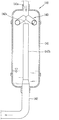
도 2는 도 1에 도시된 어큐뮬레이터를 자세히 보인 종단면도.
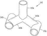
도 3은 도 2에 도시된 액냉매 분리 부재를 보인 사시도.
도 4는 본 발명의 다른 실시예에 따른 어큐뮬레이터의 내부를 보인 종단면도.
도 5는 도 4에 도시된 스크린 부재를 보인 사시도.
도 6은 본 발명의 또 다른 실시예에 따른 밀폐형 압축기의 종단면도.1 is a longitudinal sectional view of a hermetic compressor according to an embodiment of the present invention.
FIG. 2 is a vertical sectional view showing the accumulator shown in FIG. 1 in detail; FIG.
FIG. 3 is a perspective view showing the liquid refrigerant separating member shown in FIG. 2; FIG.
4 is a longitudinal sectional view showing the inside of an accumulator according to another embodiment of the present invention.
Figure 5 is a perspective view of the screen member shown in Figure 4;
6 is a longitudinal sectional view of a hermetic compressor according to another embodiment of the present invention.
이하, 본 발명에 관련된 밀폐형 압축기에 대하여 도면을 참조하여 보다 상세하게 설명한다.Hereinafter, a hermetic compressor according to the present invention will be described in detail with reference to the drawings.
서로 다른 실시예라고 하더라도, 앞선 실시예와 동일하거나 유사한 구성요소에는 동일·유사한 도면 부호를 부여하고 이에 대한 중복되는 설명은 생략하기로 한다.In other respects, the same or similar reference numerals are given to the same or similar components to those of the previous embodiment, and a duplicate description thereof will be omitted.
본 명세서에 개시된 실시예들을 설명함에 있어서 관련된 공지 기술에 대한 구체적인 설명이 본 명세서에 개시된 실시 예의 요지를 흐릴 수 있다고 판단되는 경우 그 상세한 설명을 생략한다.In the following description of the embodiments of the present invention, a detailed description of known related arts will be omitted when it is determined that the gist of the embodiments disclosed in the present specification may be obscured.
첨부된 도면은 본 명세서에 개시된 실시예들을 쉽게 이해할 수 있도록 하기 위한 것일 뿐, 첨부된 도면에 의해 본 명세서에 개시된 기술적 사상이 제한되지 않으며, 본 발명의 사상 및 기술 범위에 포함되는 모든 변경, 균등물 내지 대체물을 포함하는 것으로 이해되어야 한다.It is to be understood that the invention is not limited to the disclosed embodiments, but, on the contrary, is intended to cover various modifications and equivalent arrangements included within the spirit and scope of the invention, It should be understood that it includes water and alternatives.
단수의 표현은 문맥상 명백하게 다르게 뜻하지 않는 한, 복수의 표현을 포함한다.The singular expressions include plural expressions unless the context clearly dictates otherwise.
도 1은 본 발명의 일 실시예에 따른 밀폐형 압축기(100)를 보인 종단면도이다. 도 1을 참조하면, 본 발명에 따른 밀폐형 압축기(100)는, 케이싱(110), 구동 유닛(120) 및 압축 유닛(130)을 포함한다.1 is a longitudinal sectional view showing a
케이싱(110)은 본 발명의 밀폐형 압축기(100)의 외관을 형성하며, 후술하는 내부의 구성요소들이 장착 및 지지되는 역할을 수행한다. 케이싱(110)은, 예를 들면, 후술하는 회전축(123)의 연장 방향을 따라 길게 연장되는 원통형으로 이루어질 수 있다.The
케이싱(110)에 구비되는 흡입구(111) 및 토출구(112)는, 케이싱(110)의 내부에 냉매 및 오일이 출입되는 통로 역할을 수행한다. 본 실시예에서는 도 1에 보인 것과 같이, 흡입구(111)는 케이싱(110)의 일 측면에 연결되고, 토출구(112)는 케이싱(110)의 상부에 위치될 수 있다.The
흡입구(111)는 본 발명의 밀폐형 압축기(100)가 연결된 냉동사이클의 증발기(evaporator, 10)로부터의 흡입 배관과 케이싱(110)을 연통시키는 것일 수 있고, 토출구(112)는 본 발명의 밀폐형 압축기(100)가 연결된 냉동사이클의 응축기(condenser)로 향하는 토출 배관과 케이싱(110)을 연통시키는 것일 수 있다.The
구동 유닛(120)은 냉매를 압축하는 동력을 제공하도록 작동된다. 구동 유닛(120)은 스테이터(121), 로터(122) 및 회전축(123)을 구비한다. 도 1에 보인 것과 같이, 스테이터(121)는 케이싱(110)과 고정되도록 위치되며, 예를 들면 원통형 케이싱(110)의 내주면에 장착될 수 있다. 로터(122)는 스테이터(121)와 이격 배치되며, 스테이터(121)의 내측에 배치될 수 있다. 스테이터(121) 및 로터(122)는 본 발명의 밀폐형 압축기(100)에 전력이 인가되면 상호 간에 작용하는 힘에 의해 회전력을 발생시키고, 이에 따라 로터(122)의 중심에 연결되는 회전축(123)이 회전됨으로써 동력이 발생된다.The
한편, 압축 유닛(130)은 냉매를 압축하는 역할을 수행하며, 실린더(131), 롤러(132)를 포함하고, 베인(미도시)을 더 포함할 수 있다. 실린더(131)는 케이싱(110)에 고정되도록 위치되며, 롤러(132)는 회전축(123)과 연결된다. 롤러(132)는 실린더(131)의 내측에 위치되고, 실린더(131)의 내주면과 롤러(132)의 외주면 사이에는 압축실이 형성된다. 롤러(132)의 회전에 따라 압축실은 체적이 변화되면서 회전되는데, 특히, 압축실은 베인에 의해 구획될 수 있고, 구획된 압축실에 냉매가 흡입되고 압축되어 토출될 수 있다.Meanwhile, the
본 실시예에서, 앞서 설명한 압축 유닛(130)은 구동 유닛(120)의 하 측에 위치될 수 있고, 이때, 압축 유닛(130)은 베어링에 의해 지지될 수 있다. 도 1에 보인 것과 같이, 베어링은 실린더(131)의 상부를 지지하는 메인 베어링(113)과 실린더(131)의 하부를 지지하는 서브 베어링(114)을 포함할 수 있다. 베어링은 압축 유닛(130)을 회전축(123)의 축방향으로 고정시키도록 형성될 수 있고, 특히 압축실을 밀폐시키도록 이루어질 수 있다. 또한, 베어링은 그 중심부에서는 회전축(123) 및 롤러(132)를 회전 가능하게 지지한다.In this embodiment, the
또한 본 실시예에서는, 도 1에 보인 것과 같이 실린더(131) 및 롤러(132)가 두 개씩 상하로 장착되어 압축공간이 두 개 형성될 수 있다. 흡입구(111)를 통해 흡입되는 냉매는 각각의 압축공간으로 유입되고, 실린더(131) 내부에서의 롤러(132)의 편심 회전에 의해 냉매가 압축된다. 압축된 냉매는 메인 베어링(113)의 상부에 형성되는 머플러(115)를 통과하여 토출되고, 앞서 설명한 구동 유닛(120)을 통과하여 흘러 토출구(112)로 배출된다.In this embodiment, as shown in FIG. 1, two
한편, 본 발명의 밀폐형 압축기(100)에서 케이싱(110)의 흡입구(111) 측에는 어큐뮬레이터(140)가 장착된다. 본 발명에서 흡입구(111) 측으로 유입되는 냉매는 냉동 사이클을 구성하는 증발기(10)를 통과한 냉매일 수 있다. 이때, 증발기(10)를 통과한 냉매는 냉동 사이클의 운전 환경에 따라, 완전히 기화되지 않은 상태일 수 있다. 즉, 액체 상태의 냉매(액냉매)가 흡입구(111) 측으로 유입될 수 있으며, 액냉매가 압축되는 경우 기체 상태의 냉매(기냉매)가 압축되는 경우에 비하여 동력 입력이 증대될 수 있다. 또한, 압축 유닛(130)에 구비되는 실린더(131), 롤러(132) 및 베인 등의 구성요소들이 액냉매 입자의 충돌에 의해 손상될 위험이 존재한다.Meanwhile, in the
어큐뮬레이터(140)는 위와 같은 문제점들을 완화하고자, 액냉매가 흡입구(111) 측으로 유입되는 것을 제한하도록 기능한다. 도 1에 보인 것과 같이 어큐뮬레이터(140)는 케이싱(110)의 흡입구(111) 측에 장착되도록 이루어지며, 증발기(10)를 통과한 냉매가 어큐뮬레이터(140)를 거쳐 흡입구(111)로 흡입될 수 있도록 배치될 수 있다. 이하에서는 본 발명의 밀폐형 압축기(100)에 장착되는 어큐뮬레이터(140)의 구체적인 구조 및 기능에 대하여 설명한다.The
도 2는 도 1에 도시된 어큐뮬레이터(140)를 자세히 보인 종단면도이며, 도 3은 도 2에 도시된 액냉매 분리 부재(143)를 보인 사시도이다. 도 1 내지 3을 참조하면, 어큐뮬레이터(140)는 하우징(141), 연결 튜브(142) 및 액냉매 분리 부재(143)를 포함한다. FIG. 2 is a vertical sectional view showing the
하우징(141)은 유입구(141a)를 구비하며, 유입구(141a)는 앞서 설명한 냉동 사이클의 증발기(10)와 연통되는 배관이 연결될 수 있다. 즉, 액체 및 기체 상태가 혼합된 냉매가 유입구(141a)를 통하여 하우징(141)으로 유입될 수 있다. 하우징(141)은, 액냉매와 기냉매가 서로 분리되고, 또한 액냉매가 기냉매로 기화될 수 있는 공간을 제공한다.The
도 1 및 2에 도시된 것처럼, 하우징(141)은 케이싱(110)과 고정되도록 위치될 수 있고, 케이싱(110)의 외주면에 장착되는 결합 구조를 가질 수 있다. 케이싱(110)이 회전축(123)의 축방향으로 연장되는 원통형으로 이루어지는 경우, 하우징(141)은 케이싱(110)과 나란하게 회전축(123)의 축방향으로 연장 형성되는 원통형으로 이루어질 수 있다. 본 실시예에서 회전축(123)의 축방향은 도 1 및 2에 보인 것과 같이 상하 방향이 될 수 있고, 이때, 하 측이 중력이 작용되는 방향일 수 있다. 본 실시예에서 유입구(141a)는 하우징(141)의 상단부에 위치될 수 있다.1 and 2, the
아울러, 연결 튜브(142)는 케이싱(110)과 하우징(141) 내부를 서로 연통시키는 역할을 수행한다. 연결 튜브(142)의 일 단은 하우징(141)에 삽입 장착되어, 유입구(141a)와 기설정된 간격으로 이격 배치되는 유출구(142a)를 형성한다. 도 2에 보인 것처럼, 유출구(142a)는 케이싱(110)의 상단부에 위치되는 유입구(141a)와 나란하게 상하로 배치될 수 있다. 즉, 연결 튜브(142)는 하우징(141)의 하단부에서 삽입되어 상 측으로 연장되는 연장부(142b)를 형성할 수 있다. 또한, 연결 튜브(142)의 타 단은 케이싱(110)의 흡입구(111)에 장착될 수 있다. 도 1에 도시된 바와 같이, 케이싱(110)의 측면에 형성되는 흡입구(111)에 삽입 장착될 수 있다.In addition, the
결과적으로 도 1에 보인 바와 같이, 전체적으로 연결 튜브(142)는 L자형의 형상으로 연장되어 케이싱(110)과 하우징(141)을 서로 연통시킬 수 있다. 그리고, 연결 튜브(142)의 일 단이 되는 유출구(142a)는 하우징(141)의 하부면으로부터 기설정된 높이로 이격되도록 위치될 수 있다.As a result, as shown in FIG. 1, the connecting
이때, 하우징(141)의 하부면으로부터 유출구(142a) 까지의 연장부(142b)가 위치되는 하우징(141) 내부 공간은, 그 중 적어도 일부가 액냉매가 일정 수위를 형성하며 저장되는 공간이 될 수 있다. 즉, 유입구(141a)로부터 하우징(141)으로 흘러들어온 액냉매는, 후술하는 액냉매 분리 부재(143)에 의하여 기냉매와 분리되어 하우징(141)의 하부 공간에 저장될 수 있다. 저장된 액냉매는, 연결 튜브(142)를 통하여 케이싱(110) 측으로부터 열을 전달 받음으로써 기화될 수 있게 된다.At this time, at least a part of the internal space of the
한편, 본 발명에서 유입구(141a) 및 유출구(142a) 사이에는 액냉매 분리 부재(143)가 위치된다. 액냉매 분리 부재(143)는, 유입구(141a)를 통하여 하우징(141) 내부로 유입된 액냉매가 유출구(142a)로 흘러나가 케이싱(110) 내부의 압축 유닛(130)으로 흡입되는 것을 제한하는 역할을 수행하는 구성요소이다.In the present invention, a liquid
액냉매 분리 부재(143)는, 유입구(141a)에서 하우징(141)의 내측으로 연장되도록 형성되며, 하우징(141)의 내주면을 따라 선회하는 냉매 흐름을 형성하도록 이루어진다. 즉, 액냉매 분리 부재(143)는, 유입구(141a)로 유입된 냉매가 하우징(141) 내부에서 유입구(141a) 또는 유출구(142a)를 중심으로 원주방향으로 선회되는 유동을 형성하도록 이루어진다.The liquid
액냉매 분리 부재(143)에 의하여 하우징(141)의 내주면을 선회하는 냉매 유동이 형성됨으로써, 액냉매와 기냉매는 원심력에 의해 원심 분리될 수 있다. 즉, 상대적으로 밀도가 큰 액냉매는 곡률 반경이 크게 형성되므로 하우징(141)의 내주면에 밀착될 수 있다. 아울러 액냉매는 기냉매에 비하여 점성이 상대적으로 크므로 하우징(141)의 내주면에 달라붙게 될 수 있다. 나아가, 하우징(141)의 내주면에 달라붙는 액냉매가 축적되어, 중력에 의해 하 측으로 흘러 하우징(141)의 하부 공간에 채워질 수 있다.The liquid refrigerant and the gaseous refrigerant can be centrifugally separated by the centrifugal force by forming the refrigerant flow that rotates the inner peripheral surface of the
특히, 액냉매 분리 부재(143)에 의해 형성되는 하우징(141)의 내주면을 선회하는 유동은, 유동 저항이 적고 난류(turbulence)가 형성될 가능성이 적은 유로를 형성한다. 따라서, 본 발명의 밀폐형 압축기(100)에서 냉매를 흡입하는 동력 입력의 손실이 감소될 수 있는 이점이 있다.Particularly, the flow circulating on the inner circumferential surface of the
한편, 도 2 및 3에 보인 것과 같이, 액냉매 분리 부재(143)는 연결 유로부(143a), 반경방향 유로부(143b) 및 원주방향 유로부(143c)를 구비할 수 있다. 이들은 유입구(141a)로 유입된 냉매를 직접적으로 가이드하여 위 선회 유동을 형성하도록 기능한다.2 and 3, the liquid
연결 유로부(143a)는 유입구(141a)에 삽입 장착될 수 있다. 구체적으로 연결 유로부(143a)는, 유입구(141a)에서 하 측으로 연장 형성되는 튜브 형상으로 이루어질 수 있다. 연결 유로부(143a)는 유입구(141a)에 압입 공정을 통하여 장착되도록 유입구(141a)와의 직경 관계가 설정될 수 있다.The
반경방향 유로부(143b)는 위 연결 유로부(143a)의 단부로부터 하우징(141)의 내주면을 향하여 연장 형성될 수 있다. 혹은, 연결 유로부(143a)로 유입된 냉매가 하우징(141)의 내주면을 향하도록 가이드하는 형상으로 이루어질 수 있다.The
즉, 반경방향 유로부(143b)는 연결 유로부(143a)의 단부가 위치되는 하우징(141)의 중심부로부터, 하우징(141)의 내주면이 위치되는 외곽으로 냉매를 가이드할 수 있다. 도 2 및 3에 도시된 것과 같이, 반경방향 유로부(143b)는, 연결 유로부(143a)의 단부에서 서로 분지되는 두 개의 튜브 형상으로 이루어질 수 있다. 다만, 반경방향 유로부(143b)는 반드시 두 갈래로 분지될 필요는 없고, 하나의 튜브 형상으로 연장되거나 혹은 세 갈래 이상으로 분지되는 형상으로 이루어져도 무방하다.That is, the radial
원주방향 유로부(143c)는, 반경방향 유로부(143b)의 단부를 빠져나온 냉매를 하우징(141)의 내주면을 따라 흐르도록 가이드한다. 원주방향 유로부(143c)는 위 반경방향 유로부(143b)의 단부에서 튜브 형상으로 연장되며, 하우징(141)의 내주면을 따라 원주방향으로 냉매를 선회시키도록 연장 형성될 수 있다. 도 2 및 3에 보인 것처럼, 반경방향 유로부(143b)와 원주방향 유로부(143c)는 서로 직각으로 교차되도록 연결될 수 있다.The circumferential
유입구(141a)로 유입된 냉매는, 위와 같이 형성되는 연결 유로부(143a), 반경방향 유로부(143b) 및 원주 방향 유로부를 차례로 통과하면서, 하우징(141)의 내주면 측에서 선회되는 유동을 형성할 수 있게 된다. 특히, 위 유로부들에 의해 냉매가 하우징(141)의 내주면 측으로 직접 가이드됨으로써, 원심력에 의하여 액냉매가 분리되기 전에 유출구(142a)로 빠져나갈 가능성이 극히 낮아질 수 있다. 그리고, 하우징(141) 내부로 유입된 냉매가 액냉매 분리 부재(143)를 통과한 직후부터 선회 운동되어 원심 분리가 이루어지므로, 액냉매 분리가 더욱 효과적으로 수행될 수 있다.The refrigerant flowing into the
한편, 본 발명의 일 실시예에 따른 어큐뮬레이터(140)는, 액냉매 분리 부재(143)의 하단부가, 연결 튜브(142)의 단부에 형성되는 유출구(142a)보다 하 측에 위치될 수 있다. 이러한 상하 배치 관계에 의해, 액냉매가 유출구(142a)로 배출되는 것이 더욱 제한될 수 있다.The
구체적으로, 액냉매 분리 부재(143)를 구성하는 반경방향 유로부(143b) 또는 원주방향 유로부(143c)는 각각 반경 방향 및 원주 방향으로 연장되면서, 동시에 하 측으로 경사지게 연장되도록 이루어질 수 있다. 도 2 및 3에 보인 것과 같이, 본 실시예는 반경방향 유로부(143b)만이 연결 유로부(143a)로부터 멀어지면서 하 측으로 연장되는 구조를 보이고 있다. 다만, 반경방향 유로부(143b)뿐만 아니라, 원주방향 유로부(143c)도 하 측을 향하도록 기설정된 각도를 이루어 경사지게 연장 형성될 여지도 있다.Specifically, the
결과적으로 액냉매 분리 부재(143)의 단부, 즉, 원주방향 유로부(143c)의 단부는 유출구(142a)보다 하 측에 위치되도록 배치될 수 있다. 액냉매 분리 부재(143)의 단부를 통과하여 하우징(141) 내부로 유입된 액냉매는, 상대적으로 기냉매보다 밀도가 높고 중력에 의해 하우징(141)의 하 측으로 이동될 가능성이 높다. 반면에 상대적으로 가벼운 상태의 기냉매는 하우징(141)의 하부 공간을 채우면서 유출구(142a)로 배출될 수 있게 된다. 즉, 본 실시예에서는 액냉매와 기냉매의 분리 작용이 원심력뿐만 아니라 중력의 영향에 의해서도 수행될 수 있게 된다.As a result, the end of the liquid
이상에서는 본 발명의 일 실시예에 따라 액냉매를 원심 분리하도록 이루어지는 액냉매 분리 부재(143)의 구조 및 배치에 대하여 설명하였다. 이하에서는 본 발명의 다른 실시예에 따라, 어큐뮬레이터(140) 내부에 추가적으로 구비될 수 있는 스크린 부재(244)에 대하여 설명하기로 한다.The structure and arrangement of the liquid
도 4는 본 발명의 다른 실시예에 따른 어큐뮬레이터(240)의 종단면도이며, 도 5는 도 4에 도시된 스크린 부재(244)를 보인 사시도이다. 도 4 및 5를 참조하면, 본 발명의 다른 실시예에 따른 어큐뮬레이터(240)는 액냉매의 유출 방지를 위하여 스크린 부재(244)를 더 포함한다.FIG. 4 is a longitudinal sectional view of an
스크린 부재(244)는, 액냉매 분리 부재(143) 또는 유입구(141a)와, 유출구(142a)의 사이 공간에 위치될 수 있다. 그리고, 유입구(141a) 측에서 바라보았을 때, 유출구(142a)를 오버랩하도록 형성될 수 있다. 도 4 및 5에 보인 것과 같이, 스크린 부재(244)는 하우징(141)의 내부를 상하로 구획할 수 있는 원판형으로 형성될 수 있다.The
본 실시예에서, 스크린 부재(244)는 홀더부(244a)와 연통부(244b)를 구비할 수 있다. 홀더부(244a)와 연통부(244b)는 각각 원판형의 스크린 부재(244)의 외주면에 형성되는 부분일 수 있다. 홀더부(244a)는 하우징(141)의 내주면에 고정되도록 스크린 부재(244)의 외주면에서 연장 형성될 수 있다.In this embodiment, the
도 5에 보인 것과 같이, 홀더부(244a)는 스크린 부재(244)의 둘레를 따라 원주 방향으로 이격되도록 복수 개가 구비될 수 있다. 홀더부(244a)는 하우징(141)의 내주면에 접촉되어 스크린 부재(244)를 지지하도록 이루어진다.As shown in Fig. 5, a plurality of
또한 연통부(244b)는, 하우징(141) 내부에서 스크린 부재(244)의 상 측과 하 측 공간 사이의 냉매를 서로 통과시키도록 이루어질 수 있다. 구체적으로, 본 실시예에서는 연통부(244b)가 복수 개의 홀더부(244a) 사이사이에 배치되도록 이루어질 수 있다. 즉, 홀더부(244a)를 포함하는 스크린 부재(244)가 하나의 원판형으로 이루어진다면, 연통부(244b)는 홀더부(244a) 사이사이의 스크린 부재(244)의 외주면에서 중심을 향해 리세스되는 공간으로 이루어질 수 있다.The
즉, 본 실시예의 연통부(244b)는 하우징(141)의 내주면과 인접하게 위치되도록 스크린 부재(244)의 둘레를 따라 형성될 수 있다.That is, the communicating
본 실시예와 같이 스크린 부재(244)가 더 부가됨으로써, 본 발명의 어큐뮬레이터(140)는 유출구(142a)로 액냉매가 유입될 수 있는 가능성이 더욱 감소될 수 있다. 나아가, 어큐뮬레이터(140) 내부의 구성요소들이 이탈되어 부유되거나, 다른 이물질이 하우징(141) 내부로 유입되더라도 유출구(142a)를 통하여 기냉매와 함께 흘러나가는 것이 방지될 수 있다. 따라서, 본 발명의 밀폐형 압축기(100)의 동작 시 신뢰성 및 안정성이 보장될 수 있다.As the
또한, 스크린 부재(244)가 외주면에 형성되는 홀더부(244a)와 연통부(244b)를 구비함으로써, 상하 방향으로 냉매가 소통될 수 있으면서도, 하우징(141)의 내주면에 안정되도록 고정될 수 있다.Since the
아울러, 본 발명의 다른 실시예의 어큐뮬레이터(140)에 장착되는 스크린 부재(244)는, 도 4 및 5에 보인 것과 같이, 상 측으로 볼록한 형상으로 이루어질 수 있다. 즉, 스크린 부재(244)는 하우징(141)의 내주면을 향하여 반경이 증가됨에 따라 하 측을 향하도록 경사지게 형성될 수 있다. 이와 같이, 중심부보다 외주면 측이 하 측을 향하도록 이루어지는 스크린 부재(244)는, 유출구(142a)를 더 효과적으로 감싸 이물질 또는 액냉매의 유출을 더 효과적으로 제한할 수 있다.In addition, the
이상의 본 발명의 다른 실시예를 통하여, 앞선 본 발명의 일 실시예에 스크린 부재(244)가 추가되는 구성을 설명하였다. 이하에서는 앞선 일 실시예 또는 다른 실시예에 추가될 수 있는 어큐뮬레이터(340)의 구조적 특징에 대하여, 본 발명의 또 다른 실시예로서 설명한다.Through the other embodiments of the present invention described above, the configuration in which the
도 6은 본 발명의 또 다른 실시예에 따른 밀폐형 압축기(100)의 종단면도이다. 도 6에 도시된 바와 같이, 본 발명의 또 다른 실시예에서, 하우징(341)의 내주면에는 원주방향을 따라 연장 형성되는 선회 가이드부(341a)가 형성될 수 있다. 선회 가이드부(341a)는 하우징(341)의 내주면에서 리세스되는 홈의 형상으로 이루어지거나, 또는 하우징(341)의 내주면에서 돌출되는 돌기의 형상으로 이루어질 수 있다. 즉, 선회 가이드부(341a)가 형성됨으로써, 하우징(341)의 내주면에 상하 방향으로 요철 또는 단차가 형성될 수 있다.6 is a longitudinal sectional view of a
도 6과 같이, 선회 가이드부(341a)가 형성되면, 본 발명에 따른 액냉매 분리 부재(143)로부터 유출되는 냉매가 보다 정확하게 하우징(341)의 내주면을 따라 선회하도록 흐를 수 있다. 즉, 냉매 유동에는, 상하 방향으로 속도 성분의 형성이 억제되고 하우징(341)의 내주면을 원주방향으로 선회하는 속도 성분이 더욱 보강될 수 있는 효과가 있다. 이에 따라, 액냉매의 원심 분리가 더욱 효과적으로 이루어질 수 있다.6, the refrigerant flowing out of the liquid
특히, 선회 가이드부(341a)는, 냉매가 하우징(341)의 내부로 유입되는 액냉매 분리 부재(143)의 단부(즉, 원주방향 유로부(143c)의 단부)와 서로 마주보는 높이에 형성될 수 있다. 이에 의해, 선회 유동이 시작되는 단계에서 냉매의 흐름이 원주방향으로 정확하게 형성될 수 있다.Particularly, the turning
혹은, 도 6과 같이, 선회 가이드부(341a)는, 하우징(341)의 내주면을 따라 하 측으로 기설정된 각도로 나선형으로 연장 형성될 수 있다. 하우징(341) 내부로 유입된 액냉매는 하우징(341) 하부의 공간에 채워지는 것이 바람직하므로, 선회 가이드부(341a)가 점차적으로 하 측을 향하도록 연장 형성됨으로써 액냉매의 분리 및 이동을 도울 수 있게 된다.Alternatively, as shown in Fig. 6, the turning
이상에서 설명한 것은 본 발명에 따른 밀폐형 압축기를 실시하기 위한 실시예들에 불과한 것으로서, 본 발명은 이상의 실시예들에 한정되지 않고, 이하의 청구범위에서 청구하는 바와 같이 본 발명의 요지를 벗어나지 않는 범위 내에서 당해 발명이 속하는 분야에서 통상의 지식을 가진 자라면 누구든지 다양한 변경 실시가 가능한 범위까지 본 발명의 기술적 사상이 있다고 할 것이다.The present invention is not limited to the above-described embodiments, and various changes and modifications may be made without departing from the spirit and scope of the present invention as defined in the following claims. It will be understood by those of ordinary skill in the art that various changes in form and details may be made therein without departing from the scope of the present invention.
10: 증발기
100: 밀폐형 압축기
110: 케이싱
111: 흡입구
112: 토출구
113: 메인 베어링
114: 서브 베어링
115: 머플러
120: 구동 유닛
121: 스테이터
122: 로터
123: 회전축
130: 압축 유닛
131: 실린더
132: 롤러
140, 240, 340: 어큐뮬레이터
141, 341: 하우징
141a: 유입구
142: 연결 튜브
142a: 유출구
142b: 연장부
143: 액냉매 분리 부재
143a: 연결 유로부
143b: 반경방향 유로부
143c: 원주방향 유로부
244: 스크린 부재
244a: 홀더부
244b: 연통부
341a: 선회 가이드부10: Evaporator 100: Hermetic compressor
110: casing 111: inlet
112: discharge port 113: main bearing
114: Sub-bearing 115: muffler
120: drive unit 121:
122: rotor 123:
130
132:
141, 341:
142:
142b: extension part 143: liquid refrigerant separating member
143a:
143c: circumferential channel portion 244: screen member
244a:
341a:
Claims (11)
상기 케이싱 내부에서 회전되는 회전축을 구동시키는 구동 유닛;
상기 케이싱에 고정되는 실린더와, 상기 회전축과 연결되어 상기 실린더 내부에서 회전되는 롤러를 구비하여, 냉매를 압축하도록 이루어지는 압축 유닛; 및
상기 흡입구로 액체 상태의 냉매가 흡입되는 것을 제한하도록 이루어지는 어큐뮬레이터를 포함하며,
상기 어큐뮬레이터는,
유입구를 구비하는 하우징;
일 단은 상기 하우징에 삽입되어 상기 유입구와 기설정된 간격으로 이격 배치되는 유출구를 형성하고 타 단은 상기 흡입구에 연결되어, 상기 케이싱과 하우징을 서로 연통시키도록 이루어지는 연결 튜브; 및
상기 유입구에서 연장 형성되고, 상기 하우징의 내주면을 따라 선회하는 냉매 흐름을 형성하도록 이루어지는 액냉매 분리 부재를 구비하는 밀폐형 압축기.A casing having a suction port and a discharge port;
A driving unit for driving a rotating shaft rotated in the casing;
A cylinder fixed to the casing, and a roller connected to the rotation shaft and rotated in the cylinder, the compression unit configured to compress the refrigerant; And
And an accumulator configured to restrict the suction of the liquid refrigerant into the suction port,
The accumulator includes:
A housing having an inlet;
One end of which is inserted into the housing and forms an outlet which is spaced apart from the inlet by a predetermined distance, and the other end of which is connected to the inlet to communicate the casing and the housing with each other; And
And a liquid refrigerant separating member extending from the inlet so as to form a refrigerant flow swirling along the inner circumferential surface of the housing.
상기 액냉매 분리 부재는,
상기 유입구에 삽입 장착되는 연결 유로부;
상기 연결 유로부의 단부로부터 상기 하우징의 내주면을 향하여 연장 형성되는 반경방향 유로부; 및
상기 반경방향 유로부의 단부에서 상기 하우징의 내주면을 따라 원주방향으로 연장 형성되는 원주방향 유로부를 구비하는 밀폐형 압축기.The method according to claim 1,
The liquid refrigerant separating member
A connection channel portion inserted into the inlet port;
A radial flow path portion extending from an end portion of the connection path portion toward the inner circumferential surface of the housing; And
And a circumferential flow path portion extending in a circumferential direction along an inner circumferential surface of the housing at an end of the radial flow path portion.
상기 반경방향 유로부는 상기 연결 유로부의 단부로부터 상기 하우징의 하 측을 향하도록 경사지게 연장 형성되는 것을 특징으로 하는 밀폐형 압축기.3. The method of claim 2,
Wherein the radial flow path portion is formed to extend from the end of the connection flow path portion so as to be inclined toward the lower side of the housing.
상기 원주방향 유로부는 상기 반경방향 유로부의 단부에서 상기 하우징의 하 측을 향하도록 경사지게 연장 형성되는 것을 특징으로 하는 밀폐형 압축기.3. The method of claim 2,
And the circumferential flow path portion is formed to extend obliquely to the lower side of the housing at an end of the radial flow path portion.
상기 액냉매 분리 부재의 하단은 상기 유출구보다 하 측에 위치되는 것을 특징으로 하는 밀폐형 압축기.The method according to claim 1,
And the lower end of the liquid refrigerant separating member is positioned below the outlet.
상기 어큐뮬레이터는 상기 액냉매 분리 부재와 상기 유출구 사이에 위치되고, 상기 유출구를 오버랩하도록 형성되는 스크린 부재를 더 포함하는 밀폐형 압축기.The method according to claim 1,
Wherein the accumulator further comprises a screen member positioned between the liquid refrigerant separation member and the outlet and formed to overlap the outlet.
상기 스크린 부재는,
상기 하우징의 내주면에 고정되도록 연장 형성되는 복수 개의 홀더부; 및
상기 홀더부 사이에 형성되어, 상하 방향으로 상기 냉매를 통과시키도록 이루어지는 연통부를 구비하는 밀폐형 압축기.The method according to claim 6,
Wherein the screen member comprises:
A plurality of holder portions extended to be fixed to the inner circumferential surface of the housing; And
And a communication portion formed between the holder portions and configured to allow the refrigerant to pass in a vertical direction.
상기 연통부는 상기 케이싱의 내주면과 인접하게 형성되는 것을 특징으로 하는 밀폐형 압축기.8. The method of claim 7,
And the communicating portion is formed adjacent to the inner peripheral surface of the casing.
상기 스크린 부재는 상기 하우징의 내주면을 향하여 반경이 증가됨에 따라 하 측을 향하도록 경사지게 형성되는 것을 특징으로 하는 밀폐형 압축기.The method according to claim 6,
Wherein the screen member is inclined toward the lower side as the radius increases toward the inner circumferential surface of the housing.
상기 하우징의 내주면에는 원주방향을 따라 연장되도록 돌출 또는 리세스되는 선회 가이드부가 형성되는 것을 특징으로 하는 밀폐형 압축기.The method according to claim 1,
Wherein the inner circumferential surface of the housing is formed with a swiveling guide portion protruding or recessed to extend along the circumferential direction.
상기 선회 가이드부는, 냉매가 상기 하우징 내부로 유입되는 상기 액냉매 분리 부재의 단부와 마주보는 높이에 형성되는 것을 특징으로 하는 밀폐형 압축기.11. The method of claim 10,
Wherein the swivel guide portion is formed at a height opposite to an end of the liquid refrigerant separating member into which the refrigerant flows into the housing.
Priority Applications (1)
| Application Number | Priority Date | Filing Date | Title |
|---|---|---|---|
| KR1020170019620A KR20180093473A (en) | 2017-02-13 | 2017-02-13 | Hermetic compressor |
Applications Claiming Priority (1)
| Application Number | Priority Date | Filing Date | Title |
|---|---|---|---|
| KR1020170019620A KR20180093473A (en) | 2017-02-13 | 2017-02-13 | Hermetic compressor |
Publications (1)
| Publication Number | Publication Date |
|---|---|
| KR20180093473A true KR20180093473A (en) | 2018-08-22 |
Family
ID=63453155
Family Applications (1)
| Application Number | Title | Priority Date | Filing Date |
|---|---|---|---|
| KR1020170019620A Withdrawn KR20180093473A (en) | 2017-02-13 | 2017-02-13 | Hermetic compressor |
Country Status (1)
| Country | Link |
|---|---|
| KR (1) | KR20180093473A (en) |
Citations (1)
| Publication number | Priority date | Publication date | Assignee | Title |
|---|---|---|---|---|
| KR20040107722A (en) | 2003-06-12 | 2004-12-23 | 엘지전자 주식회사 | Accumulator for rotary compressor |
-
2017
- 2017-02-13 KR KR1020170019620A patent/KR20180093473A/en not_active Withdrawn
Patent Citations (1)
| Publication number | Priority date | Publication date | Assignee | Title |
|---|---|---|---|---|
| KR20040107722A (en) | 2003-06-12 | 2004-12-23 | 엘지전자 주식회사 | Accumulator for rotary compressor |
Similar Documents
| Publication | Publication Date | Title |
|---|---|---|
| US9828997B2 (en) | Scroll compressor with a resonator | |
| KR100869929B1 (en) | Scroll compressor | |
| CN112160908B (en) | Pump body assembly, compressor and air conditioner | |
| US8043079B2 (en) | Hermetic compressor and refrigeration cycle device having the same | |
| EP3415761A1 (en) | Compressor having centrifugation and differential pressure structure for oil supplying | |
| JP2019056322A (en) | Compressor | |
| JPWO2012127825A1 (en) | Compressor | |
| KR20190129372A (en) | Compressor having enhanced wrap structure | |
| KR20180107482A (en) | Scroll compressor | |
| KR100751152B1 (en) | Oil Supply Structure of Scroll Compressor | |
| US10816000B2 (en) | Compressor having centrifugation structure for supplying oil | |
| JP5112090B2 (en) | Scroll compressor | |
| JP4696530B2 (en) | Fluid machinery | |
| KR20180093472A (en) | Hermetic compressor | |
| JP6385118B2 (en) | Rotary compressor | |
| JP5493958B2 (en) | Compressor | |
| KR20180093473A (en) | Hermetic compressor | |
| KR20090013041A (en) | Hermetic compressor and refrigeration cycle device using the same | |
| JP6376038B2 (en) | Oil separator | |
| JP5935035B2 (en) | Horizontal type compressor | |
| JP6074620B2 (en) | Compressor | |
| KR20180089777A (en) | Hermetic compressor | |
| KR100869928B1 (en) | Scroll compressor | |
| JP4992496B2 (en) | Rotary compressor | |
| JP5304679B2 (en) | Compressor |
Legal Events
| Date | Code | Title | Description |
|---|---|---|---|
| PA0109 | Patent application |
Patent event code: PA01091R01D Comment text: Patent Application Patent event date: 20170213 |
|
| PG1501 | Laying open of application | ||
| PC1203 | Withdrawal of no request for examination | ||
| WITN | Application deemed withdrawn, e.g. because no request for examination was filed or no examination fee was paid |