KR20180098280A - Deflector for rider sensor - Google Patents
Deflector for rider sensor Download PDFInfo
- Publication number
- KR20180098280A KR20180098280A KR1020187018517A KR20187018517A KR20180098280A KR 20180098280 A KR20180098280 A KR 20180098280A KR 1020187018517 A KR1020187018517 A KR 1020187018517A KR 20187018517 A KR20187018517 A KR 20187018517A KR 20180098280 A KR20180098280 A KR 20180098280A
- Authority
- KR
- South Korea
- Prior art keywords
- view
- field
- optical
- deflection device
- optical arrangement
- Prior art date
- Legal status (The legal status is an assumption and is not a legal conclusion. Google has not performed a legal analysis and makes no representation as to the accuracy of the status listed.)
- Ceased
Links
Images



Classifications
-
- G—PHYSICS
- G01—MEASURING; TESTING
- G01S—RADIO DIRECTION-FINDING; RADIO NAVIGATION; DETERMINING DISTANCE OR VELOCITY BY USE OF RADIO WAVES; LOCATING OR PRESENCE-DETECTING BY USE OF THE REFLECTION OR RERADIATION OF RADIO WAVES; ANALOGOUS ARRANGEMENTS USING OTHER WAVES
- G01S7/00—Details of systems according to groups G01S13/00, G01S15/00, G01S17/00
- G01S7/48—Details of systems according to groups G01S13/00, G01S15/00, G01S17/00 of systems according to group G01S17/00
- G01S7/481—Constructional features, e.g. arrangements of optical elements
- G01S7/4814—Constructional features, e.g. arrangements of optical elements of transmitters alone
-
- G—PHYSICS
- G01—MEASURING; TESTING
- G01S—RADIO DIRECTION-FINDING; RADIO NAVIGATION; DETERMINING DISTANCE OR VELOCITY BY USE OF RADIO WAVES; LOCATING OR PRESENCE-DETECTING BY USE OF THE REFLECTION OR RERADIATION OF RADIO WAVES; ANALOGOUS ARRANGEMENTS USING OTHER WAVES
- G01S17/00—Systems using the reflection or reradiation of electromagnetic waves other than radio waves, e.g. lidar systems
- G01S17/88—Lidar systems specially adapted for specific applications
- G01S17/93—Lidar systems specially adapted for specific applications for anti-collision purposes
- G01S17/931—Lidar systems specially adapted for specific applications for anti-collision purposes of land vehicles
-
- G01S17/936—
-
- G—PHYSICS
- G01—MEASURING; TESTING
- G01S—RADIO DIRECTION-FINDING; RADIO NAVIGATION; DETERMINING DISTANCE OR VELOCITY BY USE OF RADIO WAVES; LOCATING OR PRESENCE-DETECTING BY USE OF THE REFLECTION OR RERADIATION OF RADIO WAVES; ANALOGOUS ARRANGEMENTS USING OTHER WAVES
- G01S7/00—Details of systems according to groups G01S13/00, G01S15/00, G01S17/00
- G01S7/48—Details of systems according to groups G01S13/00, G01S15/00, G01S17/00 of systems according to group G01S17/00
- G01S7/481—Constructional features, e.g. arrangements of optical elements
- G01S7/4817—Constructional features, e.g. arrangements of optical elements relating to scanning
Landscapes
- Engineering & Computer Science (AREA)
- Physics & Mathematics (AREA)
- Computer Networks & Wireless Communication (AREA)
- General Physics & Mathematics (AREA)
- Radar, Positioning & Navigation (AREA)
- Remote Sensing (AREA)
- Electromagnetism (AREA)
- Optical Radar Systems And Details Thereof (AREA)
- Traffic Control Systems (AREA)
Abstract
본 발명은 라이더(Lidar) 센서용 편향 장치(30)에 관한 것이며, 상기 편향 장치는 주 광학 요소(30); 및 적어도 하나의 광학 배치 요소(32a...32d)를 포함하고, 상기 편향 장치(30)는 라이더(Lidar) 센서의 시야(200)를 규정된 방식으로 조명하도록 설계되며, 상기 광학 배치 요소(32a...32d)에 의해 상기 시야(200)의 규정된 수의 상점들(P)이 규정된 방식으로 배치될 수 있다.The present invention relates to a deflection device (30) for a Lidar sensor, the deflection device comprising a main optical element (30); And at least one optical arrangement element (32a ... 32d), the deflection arrangement (30) being designed to illuminate the field of view (200) of a Lidar sensor in a prescribed manner, the optical arrangement element 32a ... 32d can be arranged in a defined manner in a defined number of shops P of the field of view 200. [
Description
본 발명은 라이더(Lidar) 센서용 편향 장치에 관한 것이다. 본 발명은 또한 라이더 센서에 관한 것이다. 본 발명은 또한 라이더 센서용 편향 장치의 제조 방법에 관한 것이다.The present invention relates to a deflection device for a lidar sensor. The present invention also relates to a rider sensor. The present invention also relates to a method of manufacturing a deflector for a rider sensor.
종래 기술에서, 편향 거울(또는 전송 광학 유닛)을 통해 송신 광을 주변으로 안내하여 반사된 방사선을 검출하는 라이더(Lidar) 센서(예를 들어 자동차 분야에서)가 공지되어 있다. 이 경우, 거울 또는 이미징 단부는 평면 또는 "단순한" 곡면일 수 있다.In the prior art, a Lidar sensor (e.g. in the automotive field) is known which guides the transmitted light to the periphery through a deflecting mirror (or a transmission optical unit) and detects the reflected radiation. In this case, the mirror or imaging end may be a planar or "simple" curved surface.
본 발명의 과제는 라이더 센서용 개선된 편향 장치를 제공하는 것이다.It is an object of the present invention to provide an improved deflection device for a rider sensor.
제 1 양태에 따르면, 본 발명은 라이더 센서용 편향 장치로서, According to a first aspect, the present invention provides a bending device for a rider sensor,
- 주 광학 요소, 및- the primary optical element, and
- 적어도 하나의 광학 배치 요소를 포함하고,- at least one optical arrangement element,
- 상기 편향 장치는 라이더 센서의 시야를 규정된 방식으로 조명하도록 설계되며, The deflection device is designed to illuminate the field of view of the rider sensor in a defined manner,
- 상기 광학 배치 요소에 의해 시야의 규정된 수의 상점들(image points)이 규정된 방식으로 배치될 수 있는, 라이더 센서용 편향 장치를 제공한다.- a predetermined number of image points of view by the optical arrangement element can be arranged in a defined manner.
이로 인해, 바람직하게는 라이더 센서의 조명 영역이 특정하게 확장될 수 있는 것이 지원되고, 특히 이동 가능한 마이크로 미러의 제한된 이동 가능성이 보완될 수 있다. 이로 인해, 높은 분해능은 아니지만 가장자리 영역에 있는 물체 또는 사람의 존재를 검출할 수 있는, 시야의 가장자리 영역들을 조명하는 것이 가능하다. 이러한 방식으로, 제안된 편향 장치를 갖는 라이더 센서를 구비한 자동차의 안전성이 바람직하게 높아질 수 있다.As a result, it is preferable that the illumination region of the rider sensor can be specifically expanded, and in particular, the limited movable possibility of the movable micromirror can be compensated. This makes it possible to illuminate the edge regions of the field of view, which are not of high resolution, but which can detect the presence of an object or person in the edge region. In this way, the safety of a vehicle equipped with a rider sensor having the proposed deflection device can be preferably enhanced.
제 2 양태에 따르면, 상기 과제는 라이더 센서용 편향 장치의 제조 방법으로서,According to a second aspect, the above object is achieved by a method of manufacturing a deflecting device for a rider sensor,
- 주 광학 요소를 제공하는 단계; 및Providing a primary optical element; And
- 적어도 하나의 광학 배치 요소를 제공하는 단계를 포함하고,- providing at least one optical placement element,
- 상기 광학 배치 요소는 상기 주 광학 요소에 대해, 상기 편향 장치에 의해 규정된 시야가 조명될 수 있도록 배치되며,The optical arrangement element being arranged so that, with respect to the main optical element, the field of view defined by the deflection device can be illuminated,
- 상기 광학 배치 요소에 의해 시야의 규정된 수의 상점들이 규정된 방식으로 배치될 수 있는, 라이더 센서용 편향 장치의 제조 방법에 의해 해결된다.- a method of manufacturing a deflection device for a lidar sensor, in which a defined number of points of view by the optical arrangement element can be arranged in a defined manner.
편향 장치의 바람직한 실시 예들은 종속 청구항들의 대상이다.Preferred embodiments of the deflection device are subject to dependent claims.
편향 장치의 바람직한 실시 예는 광학 배치 요소가 주 광학 요소의 코너 영역에 배치되는 것을 특징으로 한다. 이로 인해, 주 광학 요소의 주 조명 영역의 특정하게 규정 가능한 확장이 제공될 수 있다. 또한, 이로 인해 바람직하게는 영역들이 가능한 한 작은 각도만큼 잘못 배치되거나 재배치되어야 한다는 것이 지원된다.A preferred embodiment of the deflecting device is characterized in that the optical arrangement element is arranged in a corner area of the main optical element. This allows a specifically defined extension of the main illumination area of the main optical element to be provided. It is also supported that this would preferably cause the areas to be misplaced or relocated as small as possible.
편향 장치의 다른 바람직한 실시 예는 시야의 수평 연장이 광학 배치 요소에 의해 확장될 수 있는 것을 특징으로 한다. 이러한 방식으로, 라이더 센서의 검출 영역이 바람직하게 확장될 수 있어서, 자동차의 안전 레벨이 바람직하게 높아진다.Another preferred embodiment of the deflection device is characterized in that the horizontal extension of the field of view can be extended by the optical arrangement elements. In this way, the detection area of the rider sensor can be preferably extended, so that the safety level of the automobile is preferably high.
조명 장치의 다른 바람직한 실시 예는 광학 배치 요소에 의해 배치된 시야의 상점들이 길게 형성되는 것을 특징으로 한다. 이러한 방식으로, 긴 상점들에 의해 분해능이 높지는 않지만, 움직이는 물체를 검출할 가능성이 있기 때문에, 라이더 센서의 검출 영역의 바람직한 확장이 실현될 수 있다. 이러한 방식으로 자동차의 안전 및 보조 시스템들이 적절하게 조정될 수 있다.Another preferred embodiment of the lighting device is characterized in that the visual field shops arranged by the optical arrangement elements are elongated. In this way, a desirable expansion of the detection area of the rider sensor can be realized because there is a possibility of detecting a moving object although the resolution is not high by the long shops. In this way, the safety and auxiliary systems of the vehicle can be adjusted appropriately.
편향 장치의 또 다른 바람직한 실시 예는 광학 배치 요소가 반사 또는 굴절 또는 회절 광학 요소로서 설계되는 것을 특징으로 한다. 이로 인해, 시야의 의도된 설계를 실현하기 위해 여러 광학 원리가 사용될 수 있다는 것이 지원된다.Another preferred embodiment of the deflecting device is characterized in that the optical arrangement element is designed as a reflective or refractive or diffractive optical element. Hence, it is supported that several optical principles can be used to realize the intended design of the field of view.
편향 장치의 또 다른 바람직한 실시 예는 편향 장치가 반사 및/또는 굴절 및/또는 회절 광학 배치 요소를 포함하는 것을 특징으로 한다. 이로 인해, 시야의 의도된 설계를 실현하기 위해 여러 광학 원리가 사용될 수 있다는 것이 지원된다.Another preferred embodiment of the deflection device is characterized in that the deflection device comprises a reflective and / or refractive and / or diffractive optical arrangement element. Hence, it is supported that several optical principles can be used to realize the intended design of the field of view.
편향 장치의 또 다른 바람직한 실시 예는 편향 장치가 편향 장치와 시야 사이의 규정된 거리에만 위치하는 특성을 갖는 것을 특징으로 한다. 이로 인해, 바람직하게는 다수의 별도의 주 광학 요소가 필요 없다는 것이 지원된다. 이로 인해, 편향 장치가 통합된 배치 요소들과 일체로 기술적으로 구현될 수 있는 것이 지원된다.Another preferred embodiment of the deflecting device is characterized in that the deflecting device has a characteristic located only at a defined distance between the deflecting device and the visual field. Thereby, it is preferably supported that a number of separate primary optical elements are not required. As a result, it is supported that the deflecting device can be technically implemented integrally with the integrated placement elements.
본 발명의 다른 특징들 및 장점들이 다수의 도면을 참조하여 이하에서 상세히 설명될 것이다. 이 경우, 공개된 모든 특징들은 청구항들에서 그 인용과 관계없이, 그리고 명세서 및 도면에서의 그 설명과 관계없이 본 발명의 대상이 된다. 동일하거나 기능적으로 동일한 구성 요소들은 동일한 도면 부호로 표시된다. 도면들은 특히 본 발명에 중요한 원리를 명확하게 나타내기 위한 것이며 척도에 맞게 도시되어 있지 않다.Other features and advantages of the present invention will be described in detail below with reference to the drawings. In this case, all features disclosed are subject of the present invention regardless of its citation in the claims, and regardless of the description in the specification and drawings. The same or functionally identical components are denoted by the same reference numerals. The drawings are intended to clearly illustrate the principles particularly pointed out in the present invention and are not shown to scale.
공개된 장치 특징들은 상응하는 공개된 방법 특징들로부터 유사하게 생기고, 역으로, 공개된 방법 특징들은 상응하는 공개된 장치 특징들로부터 유사하게 생긴다. 이는 특히, 편향 장치와 관련된 특징들, 기술적 장점들 및 실시 예들이 편향 장치의 제조 방법의 상응하는 실시 예들, 특징들 및 장점들로부터 유사한 방식으로 발생하고, 역으로, 편향 장치의 제조 방법과 관련된 특징들, 기술적 장점들 및 실시 예들이 편향 장치의 상응하는 실시 예들, 특징들 및 장점들로부터 유사한 방식으로 발생한다는 것을 의미한다.The published device features are similar to the corresponding published method features, and vice versa, the published method features are similar to the corresponding published device features. This is particularly the case when the features, technical advantages and embodiments related to the deflecting device arise in a similar way from corresponding embodiments, features and advantages of the method of manufacturing the deflecting device and, conversely, Features, technical advantages and embodiments of the present invention occur in a similar manner from the corresponding embodiments, features, and advantages of the biasing device.
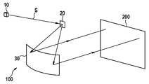
도 1은 라이더 센서용 종래의 편향 장치를 구비한 조명 장치를 도시한다.
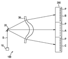
도 2는 라이더 센서용 다른 종래의 편향 장치를 구비한 다른 조명 장치를 도시한다.
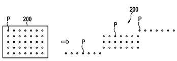
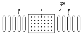
도 3 내지 도 5는 제안된 편향 장치로 구현될 수 있는 상이한 예시적인 시야 또는 조명 영역을 도시한다.
도 6은 라이더 센서용 편향 장치의 제 1 실시 예를 구비한 조명 장치를 도시한다.
도 7은 라이더 센서용 편향 장치의 제 2 실시 예를 구비한 조명 장치를 도시한다.
도 8은 편향 장치의 작동 원리를 도시한다.
도 9는 라이더 센서용 편향 장치의 제조 방법의 일 실시 예의 흐름도를 도시한다.Figure 1 shows a lighting device with a conventional deflecting device for a rider sensor.
Figure 2 shows another illumination device with another conventional deflection device for the rider sensor.
Figures 3-5 illustrate different exemplary views or areas of illumination that may be implemented with the proposed deflection device.
Fig. 6 shows a lighting device provided with a first embodiment of a deflecting device for a rider sensor.
Fig. 7 shows a lighting device having a second embodiment of a deflecting device for a lidar sensor.
Fig. 8 shows the operating principle of the deflection device.
Fig. 9 shows a flow chart of an embodiment of a method of manufacturing a deflecting device for a rider sensor.
도 1은 라이더 센서용 종래의 편향 장치(30)를 구비한 조명 장치(100)의 구성을 도시한다. 조명 장치(100)는 방사선 생성 장치(10), 바람직하게는 레이저를 포함하며, 상기 레이저는 이동 가능한 마이크로 미러(20) 상에 광의 형태로 전자기 송신 빔(S)을 방출한다. 마이크로 미러(20)에 의해, 송신 빔(S)은 시야 또는 조명 영역(200)(field of view, FOV)을 조명하는 반사 거울의 형태인 편향 장치(30)로 반사된다. 편향 장치(30)에 의해, 시야(200)의 크기가 규정된 방식으로 형성될 수 있다. 시야(200)의 기본 형태는 편향 장치(30)의 기본 형태에 실질적으로 상응한다. 마이크로 미러(20)의 주기적 이동에 의해, 송신 빔(S)은 편향 장치(30)를 통해 안내되어 전체 시야(200)를 조명한다. 시야(200) 내에 배치된 물체(도시되지 않음) 상에서 송신 빔(S)이 반사되고, 반사된 방사선이 검출되어 물체의 거리를 결정하는데 사용된다. 도 1은 반사 원리에 따른 편향 장치(30)를 도시한다.Fig. 1 shows a configuration of a
도 2는 전송 원리에 따라 설계된 다른 종래의 편향 장치(30)를 구비한 다른 조명 장치(100)를 도시한다. 이 경우 편향 장치(30)는 송신 빔(S)에 대해 중간에 합쳐지고 가장자리에서 퍼짐 특성을 갖는 전송 광학 유닛으로 이루어진다. 이러한 방식으로, 도 2에 도시된 바와 같이, 시야(200)의 중간 영역(A)은 원형 상점(image point) 또는 스캔 포인트(P)를 가지며, 시야(200)의 가장자리 영역(B, C)은 펼쳐진 또는 길게 타원형으로 형성된 상점 또는 스캔 포인트(P)를 갖는다.Fig. 2 shows another
라이더 센서에 대해 소정의 검출 영역이 실현될 수 있도록, 조명된 영역 또는 시야(200)를 변경하는 것이 제안된다. 결과적으로, 시야(200) 내의 스캔 포인트들(P)의 임의의 재분배 및 형태 변경을 허용하는 라이더 센서의 송신 및 수신 광학 유닛의 조정이 실현될 수 있다.It is proposed to change the illuminated area or field of
이동 가능한 마이크로 미러(20) 형태의 편향 유닛에 의해 미리 정해지는 "기계적" 시야는 상점들이 실제로 관심 있는 검출 영역에 형성되도록, 광 경로에 장착된 광학 요소에 의해 조정된다. 반사(예를 들어, 거울), 굴절(예를 들어, 전송 광학 유닛), 회절(예를 들어, 회절 광학 요소, DOE)과 같은 광학 요소의 여러 가지 물리적 가능성이 있다.The "mechanical" field of view predetermined by the deflecting unit in the form of a
통상적으로, 시야(200)의 가장자리 영역은 고분해능일 필요 없다. 예를 들어, 자동차에 편향 장치를 구비한 라이더 센서를 사용할 때, 차량의 주행 차선 내로 차량들의 끼어듬이 조기에 검출되는 것이 중요하다. 끼어드는 자가 가까울수록 이는 에고(Ego) 차량에게 더 위험하다. 끼어드는 자가 에고 차량에 더 가깝게 위치할수록, 이는 물체보다 더 크게 나타난다. 큰 물체이기 때문에 전체 수직 시야가 채워진다. 따라서, 이 경우 높은 수직 분해능은 필요 없다. 라이더 센서의 수평 시야의 확장이 훨씬 더 중요하다. 가능한 한 높은 분해능의 물체 검출 또는 자유면 검출을 가능하게 하기 위해, 이미지 중간에서 모든 수직 상점들이 다시 기계적 시야에 따라 검출된다.Typically, the edge region of field of
도 3 내지 도 5는 시야(200)의 여러 변경 가능성, 특히 시야(200)의 수평 확대에 대한 여러 가능성을 도시한다. 도시된 모든 변형 예에서, 변경된 시야(200)의 상점들(P)의 수는 바람직하게는 원래 시야(100)의 상점들(P)의 수와 동일하다.3-5 show various possibilities for changing the field of
도 3은 도 1의 편향 장치(30)에 의해 실현될 수 있는 바와 같은 종래의 시야(200)를 좌측에 도시한다. 도 3의 우측에는, 상부 영역에서 상점들(P)이 빠지고 중간 영역에서 좌측 및 우측에 상점들(P)이 부가된, 변경된 시야(200)가 나타난다.Fig. 3 shows a conventional field of
도 4는 변경된 시야(200)의 다른 변형 예를 도시한다. 이 경우, 시야(200)의 상점들(P)의 가장 상부의 라인 및 가장 하부의 라인이 각각 시야(200)에 대해 오프셋되어 상부에 그리고 하부에 부가된다.Fig. 4 shows another variation of the modified field of
도 5는 변경된 시야(200)의 또 다른 변형 예를 도시하며, 이 변형 예에서는 주 필드의 좌측과 우측에 상점들(P)을 가진 영역이 삽입되고, 상기 영역은 수직 방향으로 연장된다. 이러한 방식으로, 조명 장치(100)(도시되지 않음)의 낮은 수직 감도 및 높은 수평 감도가 지원된다.Figure 5 shows another variation of the modified field of
이러한 방식으로, 전술한 모든 변경된 시야(200)로 시야(200)의 원래 영역을 좌우로 넘어선 영역들의 검출이 가능해지고, 이는 시야(200)의 수평 확장을 의미한다. 결과적으로, 더 넓은 시야 또는 검출 영역을 갖는 라이더 시스템이 가능해지고, 이는 특히 움직이는 물체를 더 양호하게 검출할 수 있다.In this way, it is possible to detect areas beyond the original area of the field of
도 6은 라이더 센서용 편향 장치(30)의 제 1 실시 예를 구비한 조명 장치(100)를 도시한다. 편향 장치(30)는 주 광학 요소(31), 및 쐐기형 광학 유닛으로서 상기 주 광학 요소(31)에 추가되거나 상기 주 광학 요소(31)와 일체화된 광학 배치 요소들(32a, 32b)을 포함한다. 그 결과, 이러한 방식으로 편향 장치(30)의 일종의 "스플릿된(split)" 광학 유닛이 제공된다. 이러한 방식으로, 상부 배치 요소(32a)가 시야(200)의 좌측 영역(200a)을 조명하는 것이 지원된다. 하부 배치 요소(32b)는 송신 빔이 시야(200)의 우측 영역(200b)을 조명하는 것을 허용한다. 결과적으로, 전체 시야가 수평으로 확장될 수 있게 된다.6 shows a
도 7은 제안된 편향 장치(30)의 또 다른 실시 예를 구비한 방사선 발생 장치(10)를 갖는 조명 장치(100)를 도시한다. 편향 장치(30)의 코너 영역들에 배치되어 시야(200)(도시되지 않음)의 코너 영역을 조명하는, 총 4 개의 배치 요소(32a...32d)가 제공되는 것이 나타난다.Fig. 7 shows a
상기 편향 장치(30)에 의해, "기계적" 검출 영역으로부터 "실제" 검출 영역으로 (직사각형으로부터 원형으로, 등) 임의의 변환이 반사 광학 요소를 통해 가능하며, 상기 반사 광학 요소의 반사 영역은 규정된 기하학적 또는 규정된 광학 자유 평면일 수 있다. 시도되는 효과를 달성하기 위해, 소정 수의 반사 및/또는 투과 및/또는 회절 변경 요소가 사용될 수 있다. 또한, 이러한 목적을 위해 상기 요소들의 임의의 조합도 가능하다.By means of the
도 8은 편향 장치(30)의 제안된 효과를 달성하기 위해, 시야(200)와 편향 장치(30) 간의 규정된 최소 거리(z2)가 필요하다는 것을 도시한다. 거리(z1)가 너무 짧은 경우, 시야(200)의 영역들(A, B, C)은 서로 겹쳐서 배치된다("근거리 영역"). "원거리 영역"에서야, 즉 편향 장치(30)의 기하학적 직경(x)의 약 10 배인 거리(z2)에서, 시야(200)의 영역들(A, B, C)이 분리되어 가시될 수 있다. 이러한 방식으로, 편향 장치(30)는 별도의 또는 통합된 배치 요소들(32a...32d)을 포함하는 일체형 장치로서 설계될 수 있는 것이 지원된다.Figure 8 shows that a prescribed minimum distance z2 between the field of
도 9는 라이더 센서용 편향 장치(30)를 제조하기 위한 제안된 방법의 실시 예의 흐름도를 도시한다.9 shows a flow chart of an embodiment of the proposed method for manufacturing the
단계(300)에서, 주 광학 요소(30)가 제공된다.In
단계(310)에서, 적어도 하나의 광학 배치 요소(32a...32d)가 제공된다.At
단계(320)에서, 광학 배치 요소(31a...31d)는 주 광학 요소(30)에 대해, 편향 장치(30)에 의해 규정된 시야(200)가 조명될 수 있도록 배치되고, 광학 배치 요소(32a...32d)에 의해 시야의 규정된 수의 상점들이 규정된 방식으로 배치될 수 있다.In
바람직하게는, 주 광학 요소(30) 및 적어도 하나의 광학 배치 요소(32a...32d)를 제공하는 순서는 자유롭게 선택 가능하다.Preferably, the order of providing the main
결과적으로, 이러한 방식으로, 라이더 센서용의 개선된 송신 광학 유닛이 제공되며, 라이더 센서를 위해 다수의 송신 광학 유닛이 조합해서 사용될 수도 있다.As a result, in this way, an improved transmission optical unit for the rider sensor is provided, and a plurality of transmission optical units may be used in combination for the rider sensor.
요약하면, 본 발명에 의해, 라이더 시스템에서 광 재분배에 대한 다양한 가능성을 실현할 수 있는, 라이더 센서용 개선된 편향 장치가 제공되며, 상기 편향 장치는 마이크로 미러 이동의 제한된 가능성을 확장할 수 있게 한다. 제안된 편향 장치를 구비한 라이더 센서는 바람직하게는 자동차 분야에서 물체의 거리 및 속도 측정을 위해 사용될 수 있다.In summary, the present invention provides an improved deflection device for a rider sensor, which can realize various possibilities for light redistribution in a rider system, which allows the limited possibility of micro mirror movement to be extended. The rider sensor with the proposed deflection device can preferably be used for measuring the distance and velocity of an object in the automotive field.
결과적으로, 개선된 라이더 센서가 구현될 수 있으며, 이는 특정하게 확장된 검출 영역을 제공하며, 이로써 자동차의 안전 레벨을 상당히 높일 수 있다. 특히, 예를 들어, 물체의 검출시, 브레이크 부스터 또는 자동차의 다른 보조 시스템의 전제 조건이 수행되는 것이 가능하다.As a result, an improved rider sensor can be implemented, which provides a specifically extended sensing area, thereby significantly increasing the safety level of the vehicle. In particular, it is possible, for example, in the detection of an object, to perform the preconditions of a brake booster or other auxiliary system of the vehicle.
당업자는 본 발명의 요지를 벗어나지 않으면서 본 발명의 다양한 변형이 가능하다는 것을 알 수 있을 것이다.Those skilled in the art will appreciate that various modifications of the present invention are possible without departing from the spirit of the invention.
30
편향 장치
32a...32d
배치 요소
200
시야30 Deflector
32a ... 32d placement element
200 o'clock
Claims (10)
- 주 광학 요소(31); 및
- 적어도 하나의 광학 배치 요소(32a...32d)를 포함하고,
- 상기 편향 장치(30)는 라이더 센서의 시야(200)를 규정된 방식으로 조명하도록 설계되며,
- 상기 광학 배치 요소(32a...32d)에 의해 상기 시야(200)의 규정된 수의 상점(image point; P)이 규정된 방식으로 배치될 수 있는, 편향 장치(30).A biasing device (30) for a lidar sensor,
A main optical element (31); And
- at least one optical arrangement element (32a ... 32d)
The deflecting device 30 is designed to illuminate the field of view 200 of the rider's sensor in a prescribed manner,
- a defined number of image points (P) of said field of view (200) can be arranged in a defined manner by said optical arrangement elements (32a ... 32d).
- 주 광학 요소(31)를 제공하는 단계; 및
- 적어도 하나의 광학 배치 요소(32a...32d)를 제공하는 단계를 포함하고,
- 상기 광학 배치 요소(32a...32d)는 상기 주 광학 요소(30)에 대해, 상기 편향 장치(30)에 의해 규정된 시야(200)가 조명될 수 있도록 배치되고,
- 상기 광학 배치 요소(32a...32d)에 의해 상기 시야(200)의 규정된 수의 상점들이 규정된 방식으로 배치될 수 있는 것을 특징으로 하는 편향 장치의 제조 방법.A manufacturing method of a bending device (30) for a rider sensor,
- providing a main optical element (31); And
- providing at least one optical arrangement element (32a ... 32d)
The optical arrangement elements 32a ... 32d are arranged so that the field of view 200 defined by the deflecting device 30 can be illuminated with respect to the main optical element 30,
Characterized in that the defined number of stores of said field of view (200) can be arranged in a defined manner by said optical arrangement elements (32a ... 32d).
Applications Claiming Priority (3)
| Application Number | Priority Date | Filing Date | Title |
|---|---|---|---|
| DE102015226771.7 | 2015-12-29 | ||
| DE102015226771.7A DE102015226771A1 (en) | 2015-12-29 | 2015-12-29 | Deflection device for a lidar sensor |
| PCT/EP2016/077773 WO2017114611A1 (en) | 2015-12-29 | 2016-11-15 | Deflection device for a lidar sensor |
Publications (1)
| Publication Number | Publication Date |
|---|---|
| KR20180098280A true KR20180098280A (en) | 2018-09-03 |
Family
ID=57326395
Family Applications (1)
| Application Number | Title | Priority Date | Filing Date |
|---|---|---|---|
| KR1020187018517A Ceased KR20180098280A (en) | 2015-12-29 | 2016-11-15 | Deflector for rider sensor |
Country Status (7)
| Country | Link |
|---|---|
| US (1) | US20180372845A1 (en) |
| EP (1) | EP3397992A1 (en) |
| JP (1) | JP6679732B2 (en) |
| KR (1) | KR20180098280A (en) |
| CN (1) | CN108474855B (en) |
| DE (1) | DE102015226771A1 (en) |
| WO (1) | WO2017114611A1 (en) |
Families Citing this family (7)
| Publication number | Priority date | Publication date | Assignee | Title |
|---|---|---|---|---|
| DE102017221981A1 (en) * | 2017-12-06 | 2019-06-06 | Robert Bosch Gmbh | Micromirror-based device for emitting light rays |
| DE102017129641A1 (en) * | 2017-12-12 | 2019-06-13 | Bircher Reglomat Ag | 3D sensor system with a free-form optics |
| DE102017129639A1 (en) * | 2017-12-12 | 2019-06-13 | Bircher Reglomat Ag | 3D sensor system with scene lighting dependent on a solid angle |
| DE102018132851A1 (en) * | 2018-12-19 | 2020-06-25 | Volkswagen Aktiengesellschaft | Measuring arrangement |
| DE102020114739A1 (en) | 2020-06-03 | 2021-12-09 | HELLA GmbH & Co. KGaA | Measuring device for measuring a distance to an object |
| DE102020215663A1 (en) | 2020-12-10 | 2022-06-15 | Peter Westphal | Device for spatially resolved distance and speed measurement |
| US12444068B2 (en) | 2022-08-01 | 2025-10-14 | Lg Innotek Co., Ltd. | Optical inspection based on repetitive feature comparison |
Family Cites Families (17)
| Publication number | Priority date | Publication date | Assignee | Title |
|---|---|---|---|---|
| US4508431A (en) * | 1982-01-11 | 1985-04-02 | Massachusetts Institute Of Technology | Photorefractive laser beamsteering device |
| DE69225811T2 (en) * | 1991-09-13 | 1999-01-21 | Denso Corp | OPTICAL RADAR |
| JPH07270602A (en) * | 1994-03-31 | 1995-10-20 | Omron Corp | Light-receiving lens, light-receiving device, photoelectric sensor and laser radar using these, and vehicle equipped with laser radar |
| JPH08248133A (en) * | 1995-03-07 | 1996-09-27 | Omron Corp | Position information detection device, vehicle-mounted radar using the position information detection device, and road obstacle recognition method |
| JPH1096624A (en) * | 1996-09-20 | 1998-04-14 | Omron Corp | Distance measuring device |
| JP3636343B2 (en) * | 1998-08-27 | 2005-04-06 | オムロン株式会社 | Two-dimensional axis adjustment method of distance measuring device |
| US6723975B2 (en) * | 2001-02-07 | 2004-04-20 | Honeywell International Inc. | Scanner for airborne laser system |
| DE10323317A1 (en) * | 2003-05-23 | 2004-12-16 | Conti Temic Microelectronic Gmbh | Car object detection or distance measurement optical system path folding unit uses silicon micromirror reflectors |
| US7064810B2 (en) * | 2003-09-15 | 2006-06-20 | Deere & Company | Optical range finder with directed attention |
| DE102005028570B4 (en) * | 2005-06-21 | 2012-12-13 | Diehl Bgt Defence Gmbh & Co. Kg | Distance measuring device and distance measuring method |
| JP5105090B2 (en) * | 2008-10-16 | 2012-12-19 | トヨタ自動車株式会社 | Casting internal defect inspection support apparatus and method |
| US8169596B2 (en) * | 2009-08-17 | 2012-05-01 | Seegrid Corporation | System and method using a multi-plane curtain |
| US8917395B2 (en) * | 2010-04-19 | 2014-12-23 | Florida Atlantic University | MEMS microdisplay optical imaging and sensor systems for underwater scattering environments |
| JP2012226020A (en) * | 2011-04-15 | 2012-11-15 | Toyota Central R&D Labs Inc | Distance measuring instrument |
| JP6025014B2 (en) * | 2012-02-22 | 2016-11-16 | 株式会社リコー | Distance measuring device |
| JP2014145744A (en) * | 2013-01-30 | 2014-08-14 | Ricoh Co Ltd | Object detection device |
| KR101551667B1 (en) * | 2013-11-27 | 2015-09-09 | 현대모비스(주) | LIDAR Sensor System |
-
2015
- 2015-12-29 DE DE102015226771.7A patent/DE102015226771A1/en active Pending
-
2016
- 2016-11-15 WO PCT/EP2016/077773 patent/WO2017114611A1/en not_active Ceased
- 2016-11-15 EP EP16797532.5A patent/EP3397992A1/en not_active Withdrawn
- 2016-11-15 US US16/066,745 patent/US20180372845A1/en not_active Abandoned
- 2016-11-15 CN CN201680076773.5A patent/CN108474855B/en active Active
- 2016-11-15 JP JP2018534078A patent/JP6679732B2/en active Active
- 2016-11-15 KR KR1020187018517A patent/KR20180098280A/en not_active Ceased
Also Published As
| Publication number | Publication date |
|---|---|
| JP6679732B2 (en) | 2020-04-15 |
| US20180372845A1 (en) | 2018-12-27 |
| CN108474855B (en) | 2022-07-08 |
| JP2019502122A (en) | 2019-01-24 |
| EP3397992A1 (en) | 2018-11-07 |
| DE102015226771A1 (en) | 2017-06-29 |
| WO2017114611A1 (en) | 2017-07-06 |
| CN108474855A (en) | 2018-08-31 |
Similar Documents
| Publication | Publication Date | Title |
|---|---|---|
| KR20180098280A (en) | Deflector for rider sensor | |
| JP6407211B2 (en) | Camera device and its use | |
| KR102456631B1 (en) | Electromagnetic wave detection device and information acquisition system | |
| EP3674742B1 (en) | Electromagnetic wave detection device, program, and electromagnetic wave detection system | |
| US9332246B2 (en) | Time of flight camera unit and optical surveillance system | |
| JP5799211B2 (en) | Distance image sensor | |
| JP6465382B2 (en) | Object detection device and sensing device | |
| US11454706B2 (en) | Optical emission device for laser pulses with selective optical system | |
| ITMI20071931A1 (en) | OPTOELECTRONIC MONITORING WITH TEST BY MEANS OF DYNAMIZATION | |
| JP2021089288A (en) | Optical device for lidar system, lidar system, and work device | |
| KR20170071891A (en) | Multi area measuring rain sensor | |
| JP2015152574A (en) | Object detection device and distance measurement device | |
| EP3885791A1 (en) | Optical apparatus, in-vehicle system, and mobile apparatus | |
| CN111527740A (en) | Electromagnetic wave detection device and information acquisition system | |
| JP6876811B2 (en) | Optical device | |
| US20230138429A1 (en) | Optical apparatus, in-vehicle system, and moving apparatus | |
| KR20190142401A (en) | Electromagnetic wave detection device, electromagnetic wave detection system, and program | |
| KR20140028727A (en) | Rear sensing device for vehicle | |
| JP7535394B2 (en) | Image processing device and distance measuring device | |
| JP2019144219A (en) | Electromagnetic wave detection device and information acquisition system | |
| KR101806776B1 (en) | Multi area measuring rain sensor | |
| KR960034982A (en) | Vehicle collision prevention device and method using detection type optical distance measuring device | |
| EP4155774A1 (en) | Electromagnetic wave detection device and ranging device | |
| CN108351415A (en) | Sensor device and method for operating an occupant protector |
Legal Events
| Date | Code | Title | Description |
|---|---|---|---|
| PA0105 | International application |
Patent event date: 20180628 Patent event code: PA01051R01D Comment text: International Patent Application |
|
| PG1501 | Laying open of application | ||
| A201 | Request for examination | ||
| PA0201 | Request for examination |
Patent event code: PA02012R01D Patent event date: 20211112 Comment text: Request for Examination of Application |
|
| E902 | Notification of reason for refusal | ||
| PE0902 | Notice of grounds for rejection |
Comment text: Notification of reason for refusal Patent event date: 20230627 Patent event code: PE09021S01D |
|
| E601 | Decision to refuse application | ||
| PE0601 | Decision on rejection of patent |
Patent event date: 20230904 Comment text: Decision to Refuse Application Patent event code: PE06012S01D Patent event date: 20230627 Comment text: Notification of reason for refusal Patent event code: PE06011S01I |