KR20180098297A - Tire manufacturing method and plant - Google Patents
Tire manufacturing method and plant Download PDFInfo
- Publication number
- KR20180098297A KR20180098297A KR1020187020147A KR20187020147A KR20180098297A KR 20180098297 A KR20180098297 A KR 20180098297A KR 1020187020147 A KR1020187020147 A KR 1020187020147A KR 20187020147 A KR20187020147 A KR 20187020147A KR 20180098297 A KR20180098297 A KR 20180098297A
- Authority
- KR
- South Korea
- Prior art keywords
- carcass sleeve
- drum
- carcass
- radially
- sleeve
- Prior art date
- Legal status (The legal status is an assumption and is not a legal conclusion. Google has not performed a legal analysis and makes no representation as to the accuracy of the status listed.)
- Granted
Links
Images


Classifications
-
- B—PERFORMING OPERATIONS; TRANSPORTING
- B29—WORKING OF PLASTICS; WORKING OF SUBSTANCES IN A PLASTIC STATE IN GENERAL
- B29D—PRODUCING PARTICULAR ARTICLES FROM PLASTICS OR FROM SUBSTANCES IN A PLASTIC STATE
- B29D30/00—Producing pneumatic or solid tyres or parts thereof
- B29D30/06—Pneumatic tyres or parts thereof (e.g. produced by casting, moulding, compression moulding, injection moulding, centrifugal casting)
- B29D30/08—Building tyres
- B29D30/20—Building tyres by the flat-tyre method, i.e. building on cylindrical drums
- B29D30/30—Applying the layers; Guiding or stretching the layers during application
-
- B—PERFORMING OPERATIONS; TRANSPORTING
- B29—WORKING OF PLASTICS; WORKING OF SUBSTANCES IN A PLASTIC STATE IN GENERAL
- B29D—PRODUCING PARTICULAR ARTICLES FROM PLASTICS OR FROM SUBSTANCES IN A PLASTIC STATE
- B29D30/00—Producing pneumatic or solid tyres or parts thereof
- B29D30/06—Pneumatic tyres or parts thereof (e.g. produced by casting, moulding, compression moulding, injection moulding, centrifugal casting)
- B29D30/36—Expansion of tyres in a flat form, i.e. expansion to a toroidal shape independently of their building-up process, e.g. of tyres built by the flat-tyres method or by jointly covering two bead-rings
-
- B—PERFORMING OPERATIONS; TRANSPORTING
- B29—WORKING OF PLASTICS; WORKING OF SUBSTANCES IN A PLASTIC STATE IN GENERAL
- B29D—PRODUCING PARTICULAR ARTICLES FROM PLASTICS OR FROM SUBSTANCES IN A PLASTIC STATE
- B29D30/00—Producing pneumatic or solid tyres or parts thereof
- B29D30/06—Pneumatic tyres or parts thereof (e.g. produced by casting, moulding, compression moulding, injection moulding, centrifugal casting)
- B29D30/08—Building tyres
- B29D30/20—Building tyres by the flat-tyre method, i.e. building on cylindrical drums
- B29D30/24—Drums
- B29D30/242—Drums for manufacturing substantially cylindrical tyre components without cores or beads, e.g. treads or belts
Landscapes
- Engineering & Computer Science (AREA)
- Mechanical Engineering (AREA)
- Manufacturing & Machinery (AREA)
- Tyre Moulding (AREA)
Abstract
적어도 하나의 카커스 플라이와 한 쌍의 환형고정구물을 포함하는 카커스 슬리브(19)가 반경방행으로 수축된 제 1 동작상태로 배열된 토로이드형 성형드럼(30) 둘레에 끼워진다. 성형드럼(30)이 카커스 슬리브(19)의 내부에 위치되고 동시에 제 2 동작구성을 향해 팽창하면서 환형고정요소(43)의 적어도 하나의 반경방향 내부면(43a)에 대해 카커스 슬리브(19)가 토로이드형으로 성형된다. 제 2 동작상태에 도달시, 토로이드형 카커스 슬리브(19)가 성형드럼(30)에 결합된다. 상기 카커스 슬리브(19)에 결합된 성형드럼(30)은 상기 카커스 슬리브(19)상의 외부에 적어도 하나의 추가 부품 부착장치(54)에 인접하여 이송되도록 형성된다.A carousel sleeve (19) comprising at least one carcass ply and a pair of annular anchors is fitted around the toroidal forming drum (30) arranged in a first operative state in which it is retracted in radial direction. The shaping drum 30 is positioned within the carcass sleeve 19 and at the same time inflates towards the second operating configuration so that the carcass sleeve 19 against the at least one radially inner surface 43a of the annular fixed element 43 Is formed into a toroidal shape. Upon reaching the second operating state, the toroidal carcass sleeve 19 is engaged with the building drum 30. [ A forming drum 30 coupled to the carcass sleeve 19 is formed to be transported adjacent to at least one additional component attaching device 54 on the carcass sleeve 19.
Description
본 발명은 타이어 제조방법 및 플랜트에 관한 것이다.The present invention relates to a tire manufacturing method and a plant.
보다 상세하게는, 본 발명은 최종 생성물을 얻기 위해 연이어 가황 사이클이 적용되는 생타이어를 제조하는데 사용되는 방법 및 장치에 관한 것이다.More particularly, the present invention relates to a method and apparatus used to produce a green tire to which a vulcanizing cycle is applied successively to obtain an end product.
차륜용 타이어는 일반적으로 대게 "비드"라는 이름으로 식별되는 영역에 통합된 각각의 환형고정구조와 맞물리는 대향단부 플랩을 각각 갖고, 내경이 각각의 마운팅 림 상에 타이어의 소위 "피팅 직경"과 실질적으로 일치하는 적어도 하나의 카커스 플라이를 포함하는 카커스 구조를 구비한다.Wheel tires typically have opposing end flaps that engage respective annular anchoring structures incorporated in regions generally identified by the name "bead ", and the inner diameter is defined by the so-called" fitting diameter "of the tire on each mounting rim And a carcass structure comprising at least one substantially conforming carcass ply.
카커스 구조는 교차 배향 및/또는 실질적으로 타이어의 원주 전개방향에 평행한(0도) 섬유 또는 금속보강 코드를 가지며, 서로에 대해 그리고 카커스 플라이에 대해 반경방향으로 중첩 배치된 하나 이상의 벨트층을 포함할 수 있는 벨트구조와 관련있다. 트레드 밴드는 벨트구조의 반경방향 외측 위치에 부착되며, 또한 타이어를 구성하는 기타 반제품과 같이 엘라스토머 재료로 제조된다.The carcass structure may include one or more belt layers (not shown) having cross-orientation and / or substantially (0 degrees) parallel fibers or metal reinforcement cords in the circumferential deployment direction of the tire and radially overlapping each other and relative to the carcass ply To the belt structure. The tread band is attached to the radially outward position of the belt structure and is also made of an elastomeric material, such as other semi-finished products that make up the tire.
엘라스토머 재료의 각각의 사이드월이 카커스 구조의 측면 상의 축방향 외부 위치에 추가로 부착되며, 각각은 트레드 밴드의 측방향 가장자리 중 하나로부터 비드 쪽의 환형고정구조까지 뻗어 있다. "튜브리스" 타이어의 경우, 일반적으로 "라이너"라고 하는 기밀 코팅층이 타이어의 내부면을 덮는다.Each sidewall of the elastomeric material is further attached to an axially external location on the side of the carcass structure, each extending from one of the lateral edges of the tread band to the annular anchor structure on the bead side. In the case of a "tubeless" tire, the airtight coating layer commonly referred to as a "liner " covers the inner surface of the tire.
각각의 구성요소들을 조립함으로써 수행된 생타이어의 제조 후, 엘라스토머 조성물의 가교 결합을 통해 타이어의 구조적 안정화를 결정할뿐만 아니라, 필요한 경우 타이어에 소정의 트레드 패턴, 및 타이어 표면에 트레드 패턴, 타이어 사이드월에서 임의의 구별되는 또는 정보 그래픽 사인을 부여하기 위해 멜딩 및 가황 처리가 일반적으로 수행된다.After the production of the green tire performed by assembling the respective components, the structural stability of the tire is determined through cross-linking of the elastomeric composition, as well as a predetermined tread pattern on the tire and a tread pattern on the tire surface, A melting and vulcanizing process is generally performed to impart any distinguishable or informational graphic sign.
카커스 구조 및 벨트구조는 일반적으로 각각의 작업대에서 서로 별개로 만들어지고, 나중에 상호 어셈블리된다.The carcass structure and the belt structure are generally made separate from each other in the respective workbenches and later assembled with each other.
보다 상세하게, 카커스 구조의 제조는 카커스 플라이 또는 플라이들이 실질적으로 원통형인 소위 "카커스 슬리브"를 형성하도록 건조(乾造)드럼 상에 부착되는 것을 먼저 제공한다. 비드 쪽의 환형고정구조는 카커스 플라이 또는 플라이들의 대향 단부 플랩 상에 끼워지거나 형성되며, 그런 후 환형구조물 자체를 고리모양으로 감싸며 일종의 루프 형태로 둘러싼다.More specifically, the manufacture of the carcass structure first provides that the carcass ply or plies are deposited on a dry drum to form a so-called "carcass sleeve" that is substantially cylindrical. The annular anchoring structure on the bead side is fitted or formed on the opposite end flaps of the carcass ply or plies, and then surrounds the annular structure itself in an annular fashion and encloses it in the form of a loop.
소위 "크라운 구조"는 상호 반경방향 중첩으로 부착된 하나 이상의 벨트층 및 선택적으로 벨트층(들)에 대한 반경방향 외측 위치의 트레드 밴드를 포함하는 외부 슬리브의 형태로 제 2 드럼 또는 보조드럼 상에 제조된다. 크라운 구조는 보조드럼으로부터 픽업되어 카커스 슬리브에 결합된다. 이를 위해, 크라운 구조는 카커스 슬리브 둘레에 동축으로 배치되고, 그 후에 카커스 플라이 또는 플라이들이 비드의 상호 축방향 접근 및 카커스 슬리브 내부로의 압력을 받은 유체의 동시 주입에 의해 토로이드형 구성에 따라 형성되어, 카커스 플라이들이 반경방향으로 팽창하여 이들을 크라운 구조의 내부면에 부착하게 한다.The so-called "crown structure" is defined on the second drum or auxiliary drum in the form of an outer sleeve comprising at least one belt layer attached in an inter-radial overlap and optionally a tread band at a radially outward position relative to the belt layer . The crown structure is picked up from the auxiliary drum and coupled to the carcass sleeve. To this end, the crown structure is arranged coaxially around the carcass sleeve, and thereafter the carcass ply or plies are moved in a mutually axial direction of the beads and by simultaneous injection of the fluid under pressure into the carcass sleeve, Such that the carcass plies expand radially and attach them to the inner surface of the crown structure.
크라운 구조를 갖는 카커스 슬리브의 조립은 카커스 슬리브를 제조하기 위해 사용된 동일한 드럼상에서 수행될 수 있으며, 이 경우 이를 "단일 단계 제조공정"또는 "단일 공정"이라 한다.The assembly of the carcass sleeve with the crown structure can be performed on the same drum used to manufacture the carcass sleeve, in which case this is referred to as a "single stage manufacturing process" or a "single process".
소위 "2 단계" 타입의 제조 공정도 또한 공지되어 있으며, 카커스 슬리브를 만드는 데 소위 "1 단계 드럼"이 먼저 사용되는 한편, 상기 카커스 슬리브가 제 1 단계 드럼으로부터 픽업된 후 보조드럼으로부터 픽업된 크라운 구조가 이송되는 소위 "2 단계 드럼" 또는 "성형드럼"상에서 카커스 슬리브와 크라운 구조 사이의 어셈블리가 수행된다.A so-called "two-step" type production process is also known, in which a so-called "one-stage drum" is first used to create a carousel sleeve, while the carousel sleeve is picked up from the first- Assembly between the carcass sleeve and the crown structure is carried out on a so-called "two-stage drum" or "molding drum"
"엘라스토머 재료"라는 용어는 적어도 하나의 엘라스토머 폴리머와 적어도 하나의 강화 충진제를 포함한 조성물을 나타내는 것을 의미한다. 바람직하기로, 이런 조성물은 가령, 가교제 및/또는 가소제와 같은 첨가제를 더 포함한다. 가교제가 있음으로 인해, 이런 재료는 가열을 통해 가교될 수 있어, 최종 제조품을 형성한다.The term "elastomeric material" means representing a composition comprising at least one elastomeric polymer and at least one reinforcing filler. Preferably, such compositions further comprise additives such as, for example, cross-linking agents and / or plasticizers. Due to the presence of crosslinking agents, such materials can be crosslinked through heating to form the final article of manufacture.
타이어(또는 그 일부분)에 대한 곡률비는 타이어(또는 타이어의 일부)의 반경방향 면에서 또는 (타이어의) 회전축을 포함한 면에서 측정된 트레드 그 자체(또는 그 외부면)의 측방향 대향 단부가 지나는 라인으로부터 상기 단부들 간의 타이어의 코드(또는 그 일부)를 따라 측정된 거리까지 트레드 밴드(또는 그 외부면)의 반경방향 외측 지점의 거리의 비를 말한다. The curvature ratio for the tire (or a portion thereof) is determined by the radial direction of the tire (or a portion of the tire) or the radially opposite end of the tread itself (or its outer surface) measured in a plane including the axis of rotation Refers to the ratio of the distance of the radially outer point of the tread band (or its outer surface) to the distance measured along the cord (or portion thereof) of the tire between the ends from the line passing therethrough.
이륜차, 특히 오토바이용 타이어는 대개 표시적으로 약 0.15 내지 약 0.45 사이에 포함된 상대적으로 큰 곡률비를 특징으로 한다. 탑승객 자동차용 타이어에서, 곡률비는 대신 표시적으로 약 0 내지 약 0.15 사이에 포함된 상대적으로 낮은 값을 갖는다.Motorcycles, especially motorcycle tires, are typically characterized by relatively large curvature ratios that are included between about 0.15 and about 0.45 in indicia. In passenger automotive tires, the curvature ratio instead has a relatively low value, which is included between about 0 and about 0.15.
성형드럼과 관련한 곡률비는 드럼의 반경방향 평면상에 또는 드럼의 회전 축을 포함한 평면 상에 측정된 드럼 자체의 측방향 대향 단부를 통과하는 라인으로부터 상기 단부들 사이에서 상기 드럼의 현(chord)을 따라 측정된 거리까지 드럼의 외부면의 반경방향 외측 지점의 거리의 비를 말한다.The curvature ratio in relation to the forming drum may be determined by measuring the chord of the drum between the ends from a line passing on the radial plane of the drum or on a plane that includes the rotational axis of the drum and passing through the laterally opposite end of the drum itself Refers to the ratio of the distance from the radially outer point of the outer surface of the drum to the measured distance.
동일 출원인의 참조문헌 WO 2004/041520에서, 성형드럼은 카커스 구조와 벨트구조 간의 결합을 결정하기 위해 보조드럼으로부터 취한 벨트구조를 지지하는 이송부재와 상호작용하는 로봇암에 의해 전달될 수 있다. 그 다음, 로봇암은 트레드 밴드의 부착장치 및/또는 상호 결합된 카커스 및 벨트구조 상에 엘라스토머 재료로 된 연속세장요소를 증착시키도록 배열된 분배 부재를 포함하는 사이드월 부근에 성형드럼을 운반한다.In the same Applicant's reference WO 2004/041520, a building drum can be conveyed by a robotic arm that interacts with a transfer member that supports the belt structure taken from the auxiliary drum to determine the coupling between the carcass structure and the belt structure. The robotic arm then carries the building drum around a sidewall comprising an attachment device for the tread band and / or a distribution member arranged to deposit successive elongated elements of elastomeric material on the carcass and belt structure, do.
참조문헌 WO 2004/041522는 로봇암에 의해 전달되는 성형드럼이 이전에 보조드럼 상에 형성된 벨트구조의 부착을 결정한 후에 생타이어의 제조를 완료하는 장치와 상호작용하도록 이동되는 다른 예를 기술한 것이다.Reference document WO 2004/041522 describes another example in which a building drum delivered by a robot arm is moved to interact with an apparatus that completes the manufacture of a green tire after determining attachment of a belt structure previously formed on an auxiliary drum .
US 2009/0020200는 강체 드럼의 외부면 프로파일이 피가공 타이어의 내부면 프로파일을 복제한 강체 드럼에 의해 지지되는 피가공 타이어의 원주방향으로 트레드 밴드가 엘라스토머 재료로 된 연속세장요소를 나선형으로 연이어 권선함으로써 트레드 밴드가 얻어지는 이륜용 타이어의 제조를 기술한 것이다. US 2009/0020200 discloses a method in which a continuous elongate element made of an elastomeric material in the circumferential direction of a tire to be processed, in which the outer surface profile of the rigid drum is supported by a rigid drum replicating the inner surface profile of the tire to be processed, Thereby producing a tread band.
벨트구조의 부착을 개선하기 위해, WO 2015/079344의 동일 출원인은 카커스 슬리브가 반경방향으로 수축된 제 1 동작상태로 배열된 토로이드 성형드럼에 대해 반경방향 외측 위치에 배치된 건조(建造) 공정을 제안한다. 카커스 슬리브는 성형드럼이 카커스 슬리브 내부에 위치되는 동안 토로이드형 구성에 따라 성형된다. 카커스 슬리브의 성형 중에, 성형드럼은 반경방향으로 팽창된 제 2 동작상태까지 반경방향으로 팽창된다. 성형의 마지막에, 카커스 슬리브는 제 2 동작상태에서 성형드럼에 결합된다. 상기 성형된 카커스 슬리브에 결합된 성형드럼은 상기 성형된 카커스 슬리브의 반경방향 외측 위치에 적어도 하나의 벨트층을 형성하기 위한 적어도 하나의 장치 부근에 배치된다.In order to improve the attachment of the belt structure, the same applicant of WO 2015/079344 discloses a drying system in which a carcass sleeve is arranged in a radially outward position with respect to a toroidal forming drum arranged in a radially contracted first operating state, Process. The carcass sleeve is molded according to the toroidal configuration while the building drum is positioned within the carcass sleeve. During molding of the carcass sleeve, the building drum is radially expanded to a radially expanded second operating state. At the end of the forming, the carcass sleeve is engaged in the forming drum in the second operating state. A forming drum coupled to the shaped carcass sleeve is disposed in the vicinity of at least one device for forming at least one belt layer at a radially outward position of the shaped carcass sleeve.
본 출원인은 예를 들어 WO 2015/079344에 공지된 시스템이 벨트구조의 부착 후, 성형드럼에 의해 지지되는 카커스 슬리브 상에 직접 제조될 수 있는 트레드 밴드 및 사이드월과 같은 추가 구성부품의 제조에 상당한 조작상의 유연성을 제공하는 것을 주목했다. 그러나, 본 출원인은 피성형 카커스 슬리브 내에 성형드럼의 결합으로 전형적으로 상대적으로 높은 곡률비를 갖는 오토바이용 타이어의 제조와 관련하여 특히 만족스러운 정성적 결과가 얻어지는 것을 주목했다. 반면, 승용차에 일반적으로 사용되는 타이어와 같이 비교적 작은 곡률비를 갖는 타이어의 제조에서는, 품질 및 공정 반복성 면에서 어려움이 관찰된다.Applicants have found that the system, for example known in WO 2015/079344, can be used in the manufacture of additional components such as tread bands and sidewalls that can be manufactured directly on carcass sleeves supported by building drums after attachment of the belt structure And provides considerable operational flexibility. However, the Applicant has noted that particularly satisfactory qualitative results are obtained with regard to the manufacture of tires for motorcycles, which typically have a relatively high curvature ratio, by the bonding of the building drums in the molded carcass sleeve. On the other hand, difficulties are encountered in terms of quality and process repeatability in the manufacture of tires having relatively small curvature ratios, such as those commonly used in passenger cars.
실제로 이러한 목적을 위해, 예를 들어 WO 2015/079344에 공지된 시스템에서, 팽창 압력의 영향에 의해 성형된 카커스 슬리브는 실질적으로 일정한 반경을 가진 곡선 프로파일을 횡단면에서 취하는 경향이 있다. 즉, 성형의 효과로서, 카커스 플라이는 비드가 서로 가까이 이동함에 따라 곡률이 점차 증가하는 원주의 호(弧)에 따른 아치형 프로파일을 취하는 경향이 있다. Indeed, for this purpose, for example in a system known from WO 2015/079344, a carcass sleeve formed by the effect of inflation pressure tends to take a curved profile with a substantially constant radius in the cross-section. That is, as a molding effect, the carcass ply tends to take an arched profile along a circumferential arc of increasing curvature as the beads move closer together.
이러한 조건은 전형적으로 예를 들어 오토바이에 사용하기 위해 통상적으로 적용되는 높은 곡률비를 갖는 타이어의 제조에 최적이다. 실제로, 이러한 경우, 성형드럼은 피가공 타이어에 부여되는 곡률 프로파일과 일치하는 상대적으로 강조된 곡률 프로파일을 횡단면에서 가지며, 카커스 슬리브와의 결합은 성형드럼 자체의 전체 표면 확장에 대해 실질적으로 동시에 그리고 균일하게 발생하는 경향이 있다.These conditions are typically optimal for the manufacture of tires with high curvature ratios which are typically applied, for example, for use in motorcycles. In fact, in this case, the building drums have a relatively emphasized curvature profile in the cross-section corresponding to the curvature profile imparted to the work tire, and the engagement with the carcass sleeve is substantially simultaneous with the entire surface expansion of the building drum itself, And the like.
반대로, 예를 들어, 승용차에 사용하기 위해 작은 곡률비를 갖는 타이어를 가공하기에 적합한 성형드럼을 사용하면, 카커스 슬리브와 정확한 결합을 달성하는 것이 오히려 어렵다.Conversely, it is rather difficult to achieve precise engagement with the carcass sleeve, for example, if a forming drum suitable for machining a tire with a small curvature ratio for use in a passenger car is used.
본 출원인은 결합이 불균일하게 발생하는 경향이 있음을 주목했다. 특히, 국부적 접촉은 적도면에 가까운 영역에서, 카커스 슬리브가 성형드럼 자체의 외부면으로부터 여전히 떨어져 있을 때 타이어의 숄더 영역(즉, 트레드 밴드와 사이드월 사이의 전이 영역)에서 일반적으로 확인되는 상호 축방향으로 이격된 영역에서 카커스 슬리브와 성형드럼 사이에서 발생한다. 따라서, 카커스 슬리브와 건조드럼 사이의 결합 단계 및/또는 카커스 슬리브 자체의 왜곡에서 원하지 않는 상대적인 마찰이 발생할 수 있으며, 이는 제품의 품질에 악영향을 미치고 또한 구조적 무결성에 손상을 줄 수 있다.Applicants have noted that the coupling tends to occur unevenly. Particularly, the localized contact is in the region close to the equatorial plane, which is generally identified in the shoulder region of the tire (i. E., The transition region between the tread band and the sidewall) when the carcass sleeve is still far away from the outer surface of the building drum itself. Lt; / RTI > between the carcass sleeve and the forming drum. Thus, undesired relative friction may occur in the coupling step between the carcass sleeve and the drying drum and / or in the distortion of the carcass sleeve itself, which can adversely affect the quality of the product and impair structural integrity.
따라서, 본 출원인은 성형단계에서 성형드럼의 곡률 프로파일과 카커스 슬리브에 의해 취해진 프로파일 사이의 과도한 차이에서 상대적으로 작은 곡률비에 따른 타이어의 제조시 조우되는 문제점의 근원을 확인했다.The Applicant has thus ascertained the origin of the problems encountered in the manufacture of the tire due to the relatively small curvature ratio in the excessive difference between the curvature profile of the building drum and the profile taken up by the carcass sleeve in the molding step.
본 출원인은 타이어의 제조시, 특히 상대적으로 작은 곡률비로 질적 개선을 얻기 위해 성형드럼 및 성형된 카커스 슬리브가 서로 일치하는 기하학적 형상을 유지하여 카커스 슬리브 내에 상호 마찰 및/또는 구조 왜곡을 야기함이 없이 관련된 전체 표면에 걸쳐 상호 결합이 고르게 발생할 수 있음을 인식했다.The Applicant maintains the geometry of the shaping drum and formed carcass sleeves coinciding with one another in order to obtain a qualitative improvement, especially at relatively small curvature ratios, in the manufacture of tires, resulting in mutual friction and / or structural distortion in the carcass sleeve. And that the mutual coupling can occur evenly over the entire surface involved.
본 발명에 따르면, 본 출원인은 성형단계에서 카커스 슬리브에 억제동작을 구현해 이 결과가 효과적으로 달성됨으로써, 횡단면의 아치형 프로파일에 따른 반경방향 팽창이 바람직하게는 곡률비가 감소된 성형드럼의 기하학적 형상과 일치하는 편평한 성형 프로파일에 유리하게 억제되는 것을 알았다.According to the present invention, the Applicant has realized that by implementing a restraining action on the carcass sleeve in the forming step and effectively achieving this result, the radial expansion according to the arcuate profile of the cross section is preferably coincident with the geometrical shape of the forming drum with reduced curvature ratio Lt; RTI ID = 0.0 > molding profile. ≪ / RTI >
보다 상세하게, 본 발명은 타이어 제조방법에 관한 것이다. 바람직하기로, 적어도 하나의 카커스 플라이 및 한 쌍의 환형고정구조물을 포함한 카커스 슬리브를 배열하는 것이 고려된다. More particularly, the present invention relates to a tire manufacturing method. Preferably, it is contemplated to arrange a carcass sleeve including at least one carcass ply and a pair of annular anchoring structures.
바람직하기로, 반경방향으로 수축된 제 1 동작상태로 토로이드형 성형드럼을 배열하는 것이 고려된다.Preferably, it is contemplated to arrange the toroidally shaped drum in a first operative state that is contracted radially.
바람직하기로, 상기 성형드럼 반경방향 외부 위치에 상기 카커스 슬리브를 배열하는 것이 고려된다. Preferably, it is contemplated to arrange the carousel sleeve at a radially external location on the building drum.
바람직하기로, 상기 성형드럼이 상기 카커스 슬리브 내부에 배치되는 동안, 상기 적어도 하나의 카커스 슬리브를 환형 콘트라스트 부재의 적어도 하나의 반경방향 내부면에 대해 토로이드형으로 성형하는 것이 고려된다.Preferably, it is contemplated that the at least one carcass sleeve is toroidally shaped with respect to at least one radially inner surface of the annular contrast member, while the building drum is disposed within the carcass sleeve.
바람직하기로, 상기 성형드럼을 반경방향으로 팽창된 제 2 동작상태까지 팽창시키는 것이 고려된다.Preferably, it is contemplated to expand the forming drum to a radially expanded second operating condition.
바람직하게는, 상기 제 2 동작상태에서 상기 토로이드형 카커스 슬리브를 상기 성형드럼에 결합시키는 것이 고려된다.Preferably, it is contemplated to couple the toroidal carcass sleeve to the building drum in the second operating state.
바람직하게는, 상기 카커스 슬리브 외부의 추가 구성요소의 적어도 하나의 부착장치 부근에서 상기 카커스 슬리브에 결합된 상기 성형드럼을 배치하는 것이 고려된다.Advantageously, it is contemplated to arrange the building drums coupled to the carcass sleeve in the vicinity of at least one attachment of additional components external to the carcass sleeve.
또 다른 태양에 따르면, 본 발명은 타어이 제조 플랜트에 관한 것이다. 바람직하게는 본 발명은 카커스 슬리브의 결합장치를 포함한 성형 작업대가 제공된다.According to another aspect, the present invention relates to a tank manufacturing plant. Preferably, the present invention provides a shaping workbench including a coupling device of a carcass sleeve.
바람직하게는, 토로이드형 구성에 따라 카커스 슬리브를 성형하기 위해 성형 작업대에서 작동하는 성형장치가 제공된다.Preferably, a molding apparatus that operates in a molding workbench for molding a carcass sleeve according to a toroidal configuration is provided.
바람직하게는, 팽창가능한 토로이드 성형드럼이 제공되어, 성형 작업대에서 카커스 슬리브의 반경방향 내부 위치에서 결합될 수 있다.Preferably, an expandable toroidal molding drum is provided and can be engaged at a radially inward position of the carcass sleeve in the molding workbench.
바람직하게는, 카커스 슬리브 내부에서 성형드럼을 반경방향으로 팽창시키기 위해 성형 작업대에서 작동하는 액추에이터 장치가 제공된다.Preferably, an actuator device is provided that operates in a molding workbench to radially expand the forming drum within the carcass sleeve.
바람직하게는, 추가 구성요소의 부착을 위한 적어도 하나의 작업대가 제공된다.Preferably, at least one workbench for attachment of additional components is provided.
바람직하게는, 상기 토로이드형 카커스 슬리브를 운반하는 성형드럼을 성형 작업대로부터 추가 구성요소의 적어도 하나의 부착 작업대로 이송하도록 구성된 이송장치가 제공된다.Advantageously, there is provided a transfer device configured to transfer a building drum carrying the toroidal carousel sleeve from a molding workbench to at least one attachment workbench of an additional component.
바람직하게는, 액츄에이터 장치 또는 성형장치의 작동 중에 카커스 슬리브 자체에 대해 작동하여 적어도 하나의 환형 콘트라스트 부재를 성형드럼 및 카커스 슬리브 주위에 위치시키기 위해 성형 작업대에서 작동하는 구속장치가 제공된다.Preferably, a restraining device is provided which operates on the carcass sleeve itself during operation of the actuator device or molding device to operate in a molding workbench to position at least one annular contrast element around the molding drum and carcass sleeve.
본 출원인은 성형 중에 환형 콘트라스트 부재가 원주방향 확장부 둘레에 부착된 카커스 슬리브 상에 반경방향 구속작용을 가하여, 성형드럼과의 결합에 가장 적합한 형상에 따라 성형을 조절하게 한다고 생각한다. 성형드럼과의 접촉이 큰 표면 확장부에서 동시에 발생하여 성형드럼 상에 카커스 슬리브의 왜곡 및/또는 카카스 슬리브의 마찰 없이 결합을 완료하도록 카커스 슬리브를 배치하는 것이 특히 가능하다. 벨트층, 사이드월, 트레드 밴드와 같은 부가적인 타이어 구성요소는 또한 피가공 타이어의 설계 파라미터에 따라 이점적으로 선택될 수 있는 성형드럼의 기하학적 구성에 의해 부과된 정확한 사전정의된 프로파일에 따라 이미 성형된 카커스 슬리브에 직접 제조되게 한다. 그 결과 상기 추가 구성요소의 구성 정확도 및 타이어의 다른 구성요소에 대한 추가 구성요소의 위치 정확도가 더 크게 달성된다. 더욱이, 추가 구성요소의 조성물 및 구조가 서로 다른 여러 타입의 타이어를 제조할 때 큰 유연성이 달성된다. 예를 들어, 각각 특정 엘라스토머 조성물로 형성된 각각의 하나, 둘 이상의 상이한 부분들로 이루어진 트레드 밴드 및/또는 사이드월이 동일한 플랜트에서 제조될 수 있다.Applicant believes that during molding the annular contrast member applies a radial constraint on the carcass sleeve attached around the circumferential extension to control the molding according to the shape most suitable for engagement with the building drum. It is particularly possible to arrange the carcass sleeve so that contact with the building drum occurs simultaneously at the large surface extension to complete the engagement without distortion of the carcass sleeve and / or friction of the carcass sleeve on the building drum. Additional tire components, such as belt layers, sidewalls, tread bands, may also be preformed according to the precise predefined profile imposed by the geometry of the building drum, which may advantageously be selected according to the design parameters of the tire to be processed Made carcass sleeve. As a result, the configuration accuracy of the additional components and the positional accuracy of the additional components with respect to the other components of the tire are achieved to a greater extent. Moreover, greater flexibility is achieved when manufacturing different types of tires with different composition and structure of the additional components. For example, a tread band and / or a sidewall of each of one, two or more different portions each formed of a particular elastomeric composition may be produced in the same plant.
상기 태양들 중 하나 이상에서, 본 발명은 하기의 특징들 중 적어도 하나를 더 포함한다.In one or more of the above aspects, the present invention further comprises at least one of the following features.
바람직하기로, 상기 카커스 슬리브를 성형하기 전에 상기 카커스 슬리브 주위의 반경방향 외측 위치에 상기 환형 콘트라스트 부재를 배치하는 것이 또한 고려된다.It is also contemplated to arrange the annular contrast member at a radially outward position about the carcass sleeve prior to shaping the carcass sleeve.
바람직하게는, 상기 환형 콘트라스트 부재는 성형드럼이 카커스 슬리브 자체 내에 동축으로 삽입된 후에 카커스 슬리브 둘레에 배열된다.Preferably, the annular contrast member is arranged around the carcass sleeve after the building drum is coaxially inserted into the carcass sleeve itself.
따라서, 성형드럼 및 환형 콘트라스트 부재에 카커스 슬리브의 삽입이 상호 간섭없이 간단해진다.Therefore, the insertion of the carcass sleeve into the molding drum and the annular contrast member is simplified without mutual interference.
바람직하게는, 성형드럼의 팽창의 적어도 일부는 카커스 슬리브의 성형의 적어도 일부와 동시에 수행된다.Preferably, at least a portion of the expansion of the building drum is performed concurrently with at least part of the shaping of the carcass sleeve.
바람직하게는, 상기 제 2 동작상태에서, 상기 성형드럼의 반경방향 외측 표면은 상기 환형 콘트라스트 부재에 대해 상기 성형된 카커스 슬리브의 반경방향 내부면에 대해 접촉 관계로 작용한다.Advantageously, in the second operating state, the radially outer surface of the shaping drum acts in a contact relationship with respect to the radially inner surface of the molded carcass sleeve with respect to the annular contrast member.
바람직하게는, 성형드럼의 외부면은 성형드럼의 팽창 중에, 적어도 반경방향으로 팽창된 제 2 동작상태에 도달하기 전에, 카커스 슬리브로부터 이격된 상태로 유지된다.Preferably, the outer surface of the building drum remains spaced from the carcass sleeve during expansion of the building drum, before reaching a second, at least radially expanded, operating condition.
바람직하게는, 상기 성형드럼의 외부면은 상기 제 2 동작상태에 도달시 상기 카커스 슬리브의 반경방향 내부면에 대해 접촉 관계에 도달한다.Advantageously, the outer surface of the shaping drum reaches a contact relationship with the radially inner surface of the carcass sleeve upon reaching the second operating condition.
본 출원인은 성형드럼 자체의 최대 팽창 상태에 도달할 때에만 성형드럼과 카커스 슬리브 사이의 상호 접촉을 달성함으로써 카커스 슬리브와 성형드럼 사이의 상대적인 마찰 위험이 최소화된다고 생각한다.Applicant believes that the relative friction risk between the carcass sleeve and the building drum is minimized by achieving mutual contact between the building drum and the carcass sleeve only when it reaches the maximum expansion state of the building drum itself.
바람직하게는, 성형의 마지막에서, 카커스 슬리브의 내부면은 제 2 동작상태에서 성형드럼의 외부면에 의해 도달된 최대 직경보다 큰 최대 직경에 도달한다.Preferably, at the end of the forming, the inner surface of the carcass sleeve reaches a maximum diameter greater than the maximum diameter reached by the outer surface of the building drum in the second operating state.
따라서, 카커스 슬리브에 대한 마찰이 없는 경우에 성형드럼의 팽창이 발생할 수 있음이 보장된다.Thus, it is ensured that expansion of the building drum can occur in the absence of friction against the carcass sleeve.
바람직하게는, 상기 제 2 동작상태에 도달시, 상기 성형드럼의 반경방향 외부면은 적어도 상기 성형드럼 자체의 적도면에서 상기 환형 콘트라스트 부재에 대하여 상기 성형된 카커스 슬리브의 반경방향 내부면으로부터 2mm 보다 크지 않은 거리를 갖는다.Advantageously, upon reaching said second operating condition, the radially outer surface of said shaping drum is at least 2 mm from the radially inner surface of said molded carcass sleeve with respect to said annular contrast member at an equatorial plane of said shaping drum itself Have a great distance.
카커스 슬리브와 성형드럼 사이의 거리가 감소됨으로써, 카커스 슬리브의 약간의 수축 후에 균일한 상호 결합 및 마찰이 없는 경우가 촉진된다.The distance between the carcass sleeve and the forming drum is reduced, thereby promoting a uniform absence of mutual engagement and friction after slight shrinkage of the carcass sleeve.
바람직하게는, 상기 제 2 동작상태에 도달시, 상기 성형드럼의 반경방향 외부면과 상기 환형 콘트라스트 부재에 대한 상기 성형된 카커스 슬리브의 반경방향 내부면 사이의 최소 거리가 상기 성형드럼의 적도면에서 감지될 수 있다.Preferably, when the second operating condition is reached, a minimum distance between the radially outer surface of the shaping drum and the radially inner surface of the shaped carcass sleeve with respect to the annular contrast member is greater than the minimum distance from the equatorial plane of the shaping drum Can be detected.
바람직하게는, 카커스 슬리브를 성형하는 작용과 동시에 수행되는 환형 콘트라스트 부재의 반경방향 팽창작용이 또한 고려된다.Preferably, the radial expansion action of the annular contrast member, which is carried out simultaneously with the action of shaping the carcass sleeve, is also considered.
바람직하게는, 환형 콘트라스트 부재의 반경방향 확장은 환형 콘트라스트 부재의 탄성변형을 통해 발생한다.Preferably, the radial expansion of the annular contrast member occurs through an elastic deformation of the annular contrast member.
바람직하게는, 환형 콘트라스트 부재의 반경방향 확장은 제 2 동작상태에 도달할 때 성형드럼에 의해 가해지는 반경방향 추력의 효과에 의해 발생한다.Preferably, the radial expansion of the annular contrast member is caused by the effect of radial thrust exerted by the building drum when it reaches the second operating state.
바람직하게는, 환형 콘트라스트 부재는 적어도 하나의 이송링을 포함한다.Preferably, the annular contrast member comprises at least one conveying ring.
바람직하게는, 상기 이송링은 각각 수직인 제 1 병진축 및 제 2 병진축을 따라 이동 가능하다.Advantageously, the transport ring is movable along a first translational axis and a second translational axis, respectively, which are vertical.
바람직하게는, 상기 이송링은 반경방향으로 수축되는 파지상태와 해제상태 사이에서 원주방향으로 분포되고 반경방향으로 이동가능한 다수의 패드를 내부적으로 운반한다.Advantageously, the transport ring internally conveys a plurality of radially moveable pads circumferentially distributed between the gripping and retracting states that are contracted radially.
바람직하게는, 환형 콘트라스트 부재는 적어도 하나의 벨트층을 포함한다.Preferably, the annular contrast member comprises at least one belt layer.
따라서, 성형드럼과 카커스 슬리브 자체의 결합과 동시에 벨트 구조 또는 벨트 구조의 일부를 갖는 카커스 슬리브의 어셈블리를 얻을 수 있어, 생산 효율을 향상시키고 생산 플랜트를 단순화할 수 있다.Accordingly, it is possible to obtain an assembly of a carcass sleeve having a belt structure or a part of a belt structure simultaneously with the coupling of the forming drum and the carcass sleeve itself, thereby improving the production efficiency and simplifying the production plant.
바람직하게는, 환형 콘트라스트 부재는 이송링 내에 결합된 적어도 하나의 벨트층을 포함한다.Preferably, the annular contrast member comprises at least one belt layer coupled within the transport ring.
바람직하게는, 보조드럼 둘레에 적어도 하나의 벨트층을 형성하는 단계; 상기 적어도 하나의 벨트층 둘레에 이송링을 결합시키는 단계; 상기 적어도 하나의 벨트층을 상기 보조드럼으로부터 제거하고 이를 상기 카커스 슬리브 둘레에 위치시키기 위해 상기 이송링을 이동시키는 단계의 동작에 의해 상기 환형 콘트라스트 부재를 배열하는 것이 더 고려된다. Preferably, forming at least one belt layer around the auxiliary drum; Coupling a transferring ring around the at least one belt layer; It is further contemplated to arrange the annular contrast member by operation of removing the at least one belt layer from the auxiliary drum and moving the conveying ring to position it around the carcass sleeve.
바람직하게는, 상기 벨트층을 형성하는 작용은 밴드형 반제품을 상기 보조 드럼 둘레에 원주방향으로 감싸고 상기 밴드형 반제품의 대향 단부를 버트-조인트(butt-joint)하는 것을 포함한다.Preferably, the action of forming the belt layer includes circumferentially wrapping the band-shaped semi-finished product around the auxiliary drum and butt-jointing the opposite ends of the band-shaped semi-finished product.
따라서, 카커스 슬리브상의 벨트 구조의 제조 및 결합은 광범위하게 테스트되고 주요 설비 투자 없이 종래의 장비를 사용함으로써 달성될 수있다. 특히, 보조드럼의 사용은 기하학적으로 정밀한 원통형 기준 상에 벨트 구조를 제조할 수 있게 한다.Thus, the fabrication and coupling of belt structures on carcass sleeves can be achieved by extensive testing and using conventional equipment without major equipment investment. In particular, the use of ancillary drums makes it possible to fabricate a belt structure on a geometrically precise cylindrical reference.
바람직하게는, 상기 추가 구성요소 부착장치는 상기 성형 작업대에 대하여 멀리 떨어진 생타이어 완성라인에 설치된다.Preferably, the additional component attachment device is installed in a green tire completion line that is remote from the forming workbench.
바람직하게는, 상기 추가 구성요소는 상기 카커스 슬리브상의 반경방향 외측 위치에 적용된 적어도 하나의 벨트층을 포함한다.Advantageously, said further component comprises at least one belt layer applied at a radially outward position on said carcass sleeve.
바람직하게는, 상기 벨트층은 카커스 슬리브의 원주방향 전개 주위에 인접하여 연속적으로 배열된 복수의 스트립형 요소의 순차적인 부착에 의해 만들어진다.Advantageously, the belt layer is made by sequential attachment of a plurality of strip-like elements arranged continuously adjacent the circumferential development of the carcass sleeve.
본 출원인은 이것이 완제품의 고품질 정도와 함께 더 큰 생산 유연성을 얻을 수 있다고 생각한다.Applicants believe that this can achieve greater production flexibility with the high quality of the article.
바람직하게는, 상기 추가 구성요소는 카커스 슬리브에 반경방향 외측 위치에 부착되는 적어도 하나의 트레드 밴드를 포함한다.Advantageously, the further component comprises at least one tread band attached to the carcass sleeve in a radially outward position.
바람직하게는, 트레드 밴드는 상기 카커스 슬리브의 반경방향 외부면 주위에 인접하여 연속적으로 배열된 원주 커버링 턴에 따라 엘라스토머 재료로 된 적어도 하나의 연속세장요소를 권선함으로써 제조된다.Preferably, the tread band is made by winding at least one continuous elongate element made of an elastomeric material in accordance with a circumferential covering turn arranged continuously adjacent to the radially outer surface of the carcass sleeve.
바람직하게는, 상기 추가 구성요소는 상기 카커스 슬리브에 대해 측방향으로 부착된 적어도 하나의 사이드월을 포함한다.Advantageously, said additional component comprises at least one side wall attached laterally to said carcass sleeve.
바람직하게는, 상기 사이드월은 상기 카커스 슬리브의 외부면에 인접하여 연속적으로 배열된 원주 커버링 턴에 따라 엘라스토머 재료로 된 적어도 하나의 연속세장요소를 권선함으로써 제조된다.Advantageously, said sidewalls are made by winding at least one continuous elongate element made of an elastomeric material in accordance with a circumferential covering turn arranged continuously adjacent to the outer surface of said carcass sleeve.
바람직하게는, 상기 카커스 슬리브는 적어도 하나의 건조 작업대에서 제조되고 이어서 성형 작업대로 이송된다.Preferably, the carcass sleeve is manufactured in at least one drying station and then transported to a forming station.
바람직하게는, 카커스 슬리브의 성형은 카커스 슬리브 내에 팽창 작동유체를 주입함으로써 수행된다.Preferably, shaping of the carcass sleeve is performed by injecting an expansion working fluid into the carcass sleeve.
바람직하게는, 카커스 슬리브의 성형은 서로 동축으로 대면하는 한 쌍의 플랜지 요소의 상호 접근 및 카커스 슬리브의 각각의 축방향 대향 단부에 의해 지지되는 각각의 환형고정구조물과 동작가능하게 결합을 통해 발생한다.Preferably, the shaping of the carcass sleeve is carried out by operatively engaging respective annular anchoring structures supported by respective axially opposite ends of the carcass sleeve and the mutual approach of a pair of coaxially facing flange elements Occurs.
바람직하게는, 카커스 슬리브는 성형 작업대에 배열된 성형드럼 둘레에 동축으로 끼워진다.Preferably, the carcass sleeve is coaxially fitted around a forming drum arranged in a forming workbench.
바람직하게는, 성형드럼 둘레에 카커스 슬리브를 끼워 넣는 단계는: 플랜지 요소가 미성형 카커스 슬리브의 축방향 치수보다 큰 범위로 상호 이격되는 적재/하적 조건에 플랜지 요소를 위치시키는 단계; 상기 플랜지 요소 중 하나에 동축으로 상기 성형드럼을 결합시키는 단계; 상기 플랜지 요소들 사이에 동축으로 상기 카커스 슬리브를 위치시키는 단계; 상기 카커스 슬리브를 축방향으로 이동시켜 상기 카커스 슬리브를 성형드럼에 대해 축방향 중심 위치에 배치하는 단계를 포함한다.Preferably, the step of inserting the carcass sleeve around the forming drum comprises the steps of: placing the flange element in a loading / unloading condition wherein the flange elements are spaced apart from each other by an extent greater than the axial dimension of the unformed carcass sleeve; Coupling the forming drum coaxially to one of the flange elements; Positioning the carcass sleeve coaxially between the flange elements; And moving the carcass sleeve in an axial direction to place the carcass sleeve in an axial center position with respect to the building drum.
바람직하게는, 카커스 슬리브 주위의 반경방향 외측 위치에 상기 환형 콘트라스트 부재를 배치하는 단계는: 상기 환형 콘트라스트 부재를 상기 플랜지 요소들 사이에 동축으로 배치하는 단계; 상기 환형 콘트라스트 부재를 축방향으로 병진시켜 상기 플랜지 요소에 대해 측방향으로 배열된 대기위치로 이동시키는 단계를 포함한다.Preferably, the step of disposing the annular contrast member at a radially outward position about the carcass sleeve comprises: positioning the annular contrast member coaxially between the flange elements; And translating the annular contrast member axially into a standby position arranged laterally with respect to the flange element.
바람직하게는, 환형 콘트라스트 부재는 성형드럼과 관련한 플랜지 요소에 대해 측방향으로 동축으로 위치되고, 성형드럼으로부터 축방향으로 멀리 병진 이동된다.Preferably, the annular contrast member is coaxially positioned laterally with respect to the flange element associated with the building drum, and is translated axially away from the building drum.
바람직하게는, 상기 환형 콘트라스트 부재는 상기 환형 콘트라스트 부재가 없는 경우에 상기 액추에이터 장치의 작용시 상기 카커스 슬리브에 의해 취해지는 외경보다 작은 내경을 갖는다.Preferably, the annular contrast member has an inner diameter smaller than the outer diameter taken by the carousel sleeve in operation of the actuator arrangement in the absence of the annular contrast member.
바람직하게는, 상기 환형 콘트라스트 부재는 성형된 카커스 슬리브의 반경방향 외측 부분의 두께의 2배에 더해 팽창상태에서 성형드럼의 외경과 실질적으로 동일한 내경을 갖는다.Advantageously, the annular contrast member has an inner diameter substantially equal to the outer diameter of the building drum in the expanded state, in addition to twice the thickness of the radially outer portion of the molded carcass sleeve.
바람직하게는, 반경방향으로 수축된 제 1 동작상태의 성형드럼은 카커스 슬리브의 최소 내부 직경보다 작은 최대 외경을 갖는다.Preferably, the radially contracted first shaping drum has a maximum outer diameter smaller than the minimum inner diameter of the carousel sleeve.
바람직하게는, 상기 성형드럼은 중앙 샤프트 및 상기 중앙 샤프트 둘레에 원주방향으로 분포되고 섹터가 상기 중앙 샤프트에 인접한 제 1 동작상태로부터 상기 섹터가 멀리 이동되는 제 2 동작상태로 이동 가능한 다수의 섹터를 포함한다.Advantageously, the forming drum comprises a central shaft and a plurality of sectors that are circumferentially distributed about the central shaft and moveable from a first operative state in which the sector is adjacent the central shaft to a second operative state in which the sector is moved away .
바람직하게는, 상기 결합장치는 서로 동축으로 대면하고 상기 카커스 슬리브의 각각의 축방향 대향 단부에 의해 지지되는 각각의 환형고정구조물과 작동가능하게 결합 가능한 한 쌍의 플랜지 요소를 포함한다.Advantageously, the engagement device includes a pair of flange elements coaxially facing each other and operably engageable with respective annular anchoring structures supported by respective axially opposite ends of the carcass sleeve.
바람직하게는, 플랜지 요소 중 하나를 지지하고 상기 플랜지 요소가 미성형 카카스 슬리브의 축방향 치수보다 큰 간격으로 상호 이격되는 적재/하적 조건 및 상기 카커스 슬리브의 축방향 치수와 실질적으로 일치하는 크기로 상호 이격되는 작업 조건 간에 성형 작업대를 전환하기 위해 다른 플랜지 요소를 향해 이동 가능한 캐리지가 추가로 더 포함된다. Preferably, a load / unload condition in which one of the flange elements is supported and the flange elements are spaced apart from each other by an interval larger than the axial dimension of the unformed carcass sleeve, and a size that substantially coincides with the axial dimension of the carcass sleeve Further comprising a carriage that is movable toward the other flange element to switch the forming workbench between working conditions that are mutually spaced apart.
바람직하게는, 적재/하적 상태에서, 플랜지 요소는 미성형 카커스 슬리브의 축 방향 치수의 적어도 2 배만큼 상호 이격된다.Preferably, in the loaded / unloaded condition, the flange elements are mutually spaced by at least two times the axial dimension of the unformed carcass sleeve.
바람직하게는, 상기 환형 콘트라스트 부재는 적재/하적 상태로 배열된 플랜지 요소 사이에 끼워지도록 반경방향으로 이동할 수 있다.Preferably, the annular contrast member is movable radially to fit between flanged elements arranged in a loaded / unloaded state.
바람직하게는, 상기 환형 콘트라스트 부재는 상기 플랜지 요소 사이에 축방향으로 삽입된 작업 위치와 상기 플랜지 요소에 대해 측방향으로 배치된 대기위치 사이에서 상기 성형드럼에 동축으로 이동 가능하다.Advantageously, said annular contrast member is coaxially movable to said forming drum between a working position axially inserted between said flange elements and a standby position arranged laterally with respect to said flange element.
바람직하게는, 제 2 동작상태의 성형드럼은 약 0 내지 약 0.15 사이의 곡률비를 갖는다.Preferably, the building drums in the second operating state have a curvature ratio between about 0 and about 0.15.
추가적인 특징 및 이점은 본 발명에 따른 타이어 제조용 방법, 공정 및 플랜트의 바람직한 그러나 비배타적인 실시예의 상세한 설명으로부터 더욱 명백해질 것이다.Additional features and advantages will become more apparent from the detailed description of a preferred but non-exclusive embodiment of a method, process and plant for making a tire according to the present invention.
본 발명의 내용에 포함됨.Are included in the scope of the present invention.
이러한 설명은 단지 예시적인 것으로, 따라서 비제한적 목적으로 제공된 첨부도면을 참조로 하기에 제시된다:
도 1은 본 발명에 따른 타이어를 제조하기 위한 플랜트의 평면도를 개략적으로 도시한 것이다.
도 2는 성형 작업대에서 환형고정요소의 위치설정의 부분 측면 단면도를 개략적으로 도시한 것이다.
도 3은 성형 작업대에서 카커스 슬리브의 적재에 대한 부분 측면 단면도를 개략적으로 도시한 것이다.
도 4는 성형 작업대에 배열된 카커스 슬리브 내에 성형드럼의 삽입에 대한 부분 측면 단면도를 개략적으로 도시한 것이다.
도 5는 카커스 슬리브의 성형의 중간 단계의 측방향 부분 단면도를 개략적으로 도시한 것이다.
도 6은 카커스 슬리브의 성형의 최종 단계의 부분 측면 단면도를 개략적으로 도시한 것이다.
도 7은 성형드럼에 결합된 성형된 카커스 슬리브 상에 부가적인 구성요소의 적용을 도시한 것이다.
도 8a 및 도 8b는 본 발명에 따라 얻어질 수 있는 타이어의 각각의 예시적인 실시예의 반경방향 절반부 단면도를 개략적으로 도시한 것이다.This description is by way of example only, and is thus presented by way of non-limitative example with reference to the accompanying drawings, in which:
1 schematically shows a plan view of a plant for manufacturing a tire according to the present invention.
Figure 2 schematically shows a partial side cross-sectional view of the positioning of the annular anchoring element in the forming workbench.
Fig. 3 schematically shows a partial side cross-sectional view for loading of a carcass sleeve in a molding workbench.
Figure 4 schematically shows a partial side cross-sectional view for insertion of a building drum in a carcass sleeve arranged in a molding workbench.
Fig. 5 schematically shows a lateral partial sectional view of an intermediate stage of the forming of the carcass sleeve.
Figure 6 schematically shows a partial side cross-sectional view of a final stage of forming a carcass sleeve.
Figure 7 illustrates the application of additional components on a molded carcass sleeve coupled to a building drum.
Figures 8A and 8B schematically show a radial half sectional view of each exemplary embodiment of a tire obtainable in accordance with the present invention.
상기 도면을 참조하면, 참조부호(1)은 전체적으로 본 발명에 따른 프로세스를 구현하도록 설계된 차륜용 타이어를 제조하기 위한 플랜트를 나타낸다.Referring to the figure,
플랜트(1)는 본질적으로 불침투성 엘라스토머 재료 또는 소위 라이너(4)라고 하는 층으로 바람직하게는 내부적으로 코팅된 적어도 하나의 카커스 플라이(3)를 필수적으로 포함하는 타이어(2)(도 8a, 도 8b)를 제조하도록 설계된다. 바람직하게는 반경방향 외측 위치에서 엘라스토머 충전재(5b)를 갖는 소위 비드 코어(5a)를 포함한 2개의 환형고정구조물(5)이 카커스 플라이 또는 플라이들(3)의 각각의 단부 플랩(3a)과 치합된다. 환형고정구조물(5)은 주로 "비드"(6)라는 명으로 식별된 영역 부근에 통합되고, 각각의 마운팅 림(미도시)과 함께 타이어(2) 사이에 치합이 통상적으로 발생한다.The
각각의 비드(6)는 선택적으로 각각의 환형고정구조물(5)을 외부에서 덮고 있는 내마모성 인서트(7)(도 4)와 관련될 수 있다.Each
하나 이상의 벨트층(8a, 8b, 8c)을 포함하는 벨트구조(8)는 카커스 플라이/플라이들(3) 둘레에 원주방향으로 부착되고, 트레드 밴드(9)는 벨트구조(8)의 반경방향 외측 위치에 배치된다.A
대응하는 비드(6)로부터 각각 트레드 밴드(9)의 대응하는 축방향 외측 가장자리(9a)의 부근까지 뻗어 있는 2개의 사이드월(10)이 카커스 플라이/플라이들(3) 상의 측방향 대향위치에 도포된다.Two
각각의 사이드월(10)은 대응 비드(6)로부터 뻗어 있는 반경방향 내부(11) 및 트레드 밴드(9)의 축방향 외측 가장자리(9a) 중 하나와 결합하는 반경방향 외측부(12)를 포함할 수 있다.Each
각각의 사이드월(10)의 반경방향 내측부(11)에 추가로 또는 대안으로, 적어도 하나의 엘라스토머 강화요소(13)가 각각의 반경방향 외측부(12)와 결합하고 상기 반경방향 외측부 그 자체의 탄성계수보다 큰 탄성계수를 갖는 각각의 환형고정구조물(5) 부근에 부착될 수 있다. 선택적으로, 각 반경방향 외측부(12)는 각각의 엘라스토머 보강요소(13)의 축방향 외측부를 완전히 덮는 것이 고려될 수 있다.In addition or alternatively to the radially
카커스 플라이/플라이들(3)에 축방향 내측 위치에 적용되고 대응하는 비드(6)로부터 각각 뻗어 있는 사이드 인서트(10, 14)가 추가로 선택적으로 제공될 수 있다.Side inserts 10, 14, which are applied to the carcass ply /
도 8a의 예에서, 사이드월(10)의 반경방향 외측 정점부(12a)는 SOT 구조에 따라 트레드 밴드(9)의 축방향 외측 가장자리(9a)에 중첩된다.In the example of Fig. 8A, the radially outer apex 12a of the
도 4의 예에서, 트레드 밴드(9)의 축방향 외측 가장자리(9a)는 TOS 건설 방식에 따라 각각의 사이드월(10)의 반경방향 외측 정점(12a)에 중첩된다.In the example of Figure 4, the axially
카커스 플라이/플라이들(3)과 벨트구조(8) 사이에 엘라스토머 재료로 제조된 적어도 하나의 소위 벨트 하부층(첨부도면에 미도시)이 삽입될 수 있다.At least one so-called belt underlayer (not shown in the attached drawings) made of an elastomeric material can be inserted between the carcass ply /
벨트구조(8)의 축방향 대향 가장자리와 카커스 플라이/플라이들(3) 사이에, 엘라스토머 재료로 제조되고 서로 축방향으로 이격된 각각의 환형 언더벨트 인서트(15)가 삽입될 수 있다.Between the axially opposite edges of the
언더벨트 인서트(15)는 상기 언더벨트 인서트(15) 자체와 함께, 벨트구조(8)의 각각의 가장자리를 가로질러 배열된 소위 "쿠션 인서트"를 형성하도록 각각의 커버링부(16)와 선택적으로 결합될 수 있다.The underbelt insert 15 is provided with respective
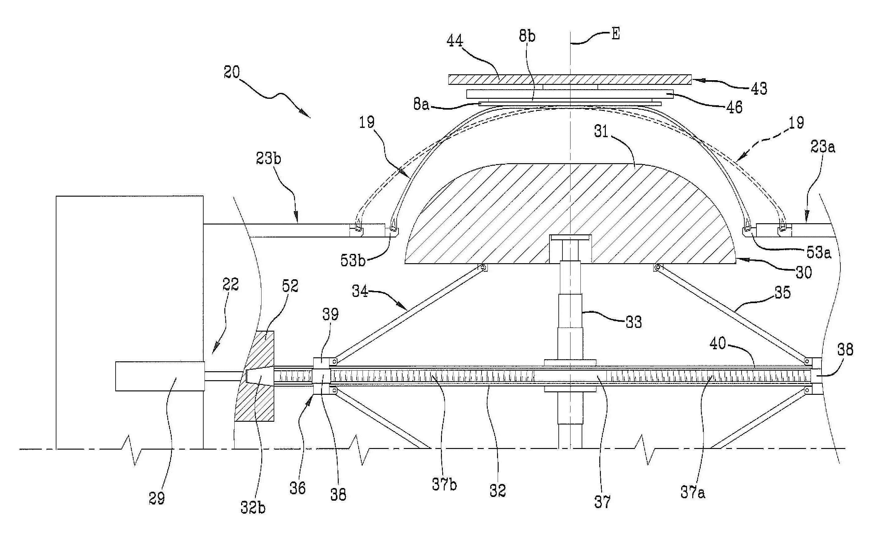
플랜트(1)는, 예를 들어 공지된 방법에 따라, 실질적으로 원통형 카커스 슬리브(19)가 제조되는 하나 이상의 건조(建造) 작업대(18)를 갖는 카커스 건조라인(17)을 포함한다. 카커스 슬리브(19)는 바람직하게는 라이너(4)에 의해 내부에 라이닝되고 각각의 단부 플랩(3a)이 예를 들어 루핑 백을 통해 각각의 환형고정구조물(5)에 결합된 적어도 하나의 카커스 플라이(3)를 포함한다. 발생시, 카커스 슬리브(19)는 각각의 비드(6)로부터 시작하여 뻗어 있는 사이드월(10) 또는 사이드월의 제 1 부분을 포함할 수 있다. 내마모성 인서트(7) 및/또는 엘라스토머 강화요소(13)가 카커스 슬리브(19) 상에 추가로 도포될 수 있다.The
카커스 건조라인(17)은 카커스 슬리브(19)의 결합장치(21)와 성형장치(22)를 포함한 성형 작업대(20)로 끝나고, 상기 건조라인 상에 동작시 카커스 슬리브(19)는 토로이드 형상을 따라 성형된다.The
결합장치(21)는 예를 들어 서로 동축방향으로 마주하고 각각의 원주방향 결합시트(24a, 24b)를 갖는 제 1 플랜지 요소(23a) 및 제 2 플랜지 요소(23b)를 포함하며, 이로써 카커스 슬리브(19)의 축방향 대향 단부에 의해 각각 지지된 환경고정구조물들(5) 중 각 하나에 동작가능하게 결합될 수 있다. The
결합장치(21)는 플랜지 요소(23a, 23b)의 축방향 이동요소(25)를 더 포함할 수 있다. 보다 상세하게는, 제 1 플랜지 요소(23a)와 같은 플랜지 요소(23a, 23b) 중 적어도 하나는, 상기 제 1 플랜지 요소(23a, 23b) 사이에 상호 정렬의 기하학적 축(X-X)에 평행하고 바람직하게는 제 2 플랜지 요소(23b)와 일체형인 고정 베이스(28)에 대해 일체형인 하나 이상의 선형 가이드(27)를 따라 이동가능한 캐리지(26)에 의해 전달되는 것이 고려될 수 있다. 선형 가이드(27)를 따라 캐리지(26)를 이동시킴으로써 성형 작업대(20)가 적재/하적 조건 및 작업 조건 사이로 전환된다. 적재/하적 조건(도 2 및 도 3)에서, 제 1 플랜지 요소(23a)는 카커스 건조라인(17)으로부터 도달한 미성형 카커스 슬리브(19)의 축방향 치수에 대해, 제 2 플랜지 요소(23b)로부터 더 큰 정도로, 대략 적어도 2배 정도 이격되어 있다. 작동 조건에서, 플랜지 요소(23a, 23b) 및 보다 구체적으로는 각각의 원주방향 결합시트(24a, 24b)는 카커스 슬리브(19)의 축방향 치수에 실질적으로 대응하는 정도로 서로 이격되어 있다.The
성형장치(22)는 예를 들어 슬리브(19) 내부의 플랜지 요소(23a, 23b) 사이에서 가압 공기 또는 다른 작동 팽윤 유체를 주입하기 위한 유체 다이내믹 서킷(미도시)을 포함할 수 있다.The
성형장치(22)는 상기 작업 조건으로부터 시작하여 서로를 향해 축방향으로 이동하기 위해 하나 또는 바람직하게는 양 플랜지 요소들(23a, 23b) 상에서 작동하는 하나 이상의 선형 액추에이터 또는 다른 축방향 핸들링 장치(29)를 더 포함할 수 있다. 플랜지 요소(23a, 23b)의 왕복 접근으로 환형고정구조물(5)의 상호 접근이 유발되어 가압된 작동 유체를 카커스 슬리브(19) 내로 동시에 주입함으로써 토로이드형 구조에 따라 카커스 슬리브(19)가 성형될 수 있게 한다. The shaping
성형 작업대(20)에서, 성형된 카커스 슬리브(19)는 카커스 슬리브 자체 내에 배열된 토로이드형의 단단하고 팽창가능한 성형드럼(3)에 결합된다.In the molding table 20, the molded
성형드럼(30)은 반경방향으로 축소된 제 1 동작상태(도 2 내지 도 4) 및 반경방향으로 팽창된 제 2 동작상태(도 6 및 도 7)로부터 팽창 가능하다. 이를 위해, 예를 들어 성형드럼(30)은 중앙 샤프트(32) 둘레에 원주방향으로 분포된 복수의 섹터(31)를 포함하는 것이 고려될 수 있다. 섹터(31)는 바람직하게는 동시에 이들이 상기 중앙 샤프트(32)에 가까워지는 제 1 동작상태로부터 상기 중앙 샤프트(32)로부터 멀어지는 제 2 동작상태까지 이동할 수 있다. 이를 위해, 중앙 샤프트(32)로부터 반경방향으로 뻗어 있는 각각의 신축가능하게 연장가능한 가이드 부재(33)에 의해 섹터들(31)이 전해는 것이 고려될 수 있다.The
섹터(31)의 이동은, 예를 들어, 각각이 각각의 대향 단부에서 상기 섹터(31) 및 중앙 샤프트(32)를 따라 슬라이딩 가능하게 끼워진 적어도 하나의 컨트롤 칼라(36) 중 하나에 힌지 결합된 제어 레버(35)를 포함하는 복귀 메커니즘(34)에 의해 달성될 수 있다. 보다 상세하게는, 각각의 제어 레버(35)와 맞물리는 섹터(31)에 대해 축방향 대향 위치에서 중앙 샤프트(32)를 따라 배치된 한 쌍의 제어 칼라(36)가 제공되는 것이 바람직하다.Movement of the
각각의 제어 칼라(36)는 중앙 샤프트(32) 내에서 동축으로 회전 가능하게 결합된 스레드 로드(37)에 작동가능하게 연결된다. 스레드 바(37)는 중앙 샤프트(32)를 따라 거의 동일 길이 또는 그 이상의 전체 길이만큼 연장되고, 2개의 대향 스레드(37a, 37b)를 각각 우측과 좌측에 지닌다. 각각의 너트 스크류(38)가 중앙 샤프트(32) 내에서 축방향으로 이동 가능한 스레드(37a, 37b)에 작동 가능하게 결합되고, 예를 들어, 길이방향 슬릿(40)에서 중앙 샤프트(32)를 반경방향으로 가로지르는 적어도 하나의 블록(39)에 의해 제어 칼라(36) 중 하나에 각각 연결된다.Each
성형 작업대(20)에서 작동하는 다른 유형의 로터리 피더 또는 다른 작동 장치(41)에 의해 수행될 수 있는 중앙 샤프트(32) 내에서 스레드 바(37)의 회전으로 스레드 바(37)의 회전 방향에 따라 제 1 또는 제 2 동작상태를 향하여 섹터(31)의 반경방향 운동에 대응하는 너트 스크류(38) 및 제어 칼라(36)의 축방향 이동이 야기된다.The rotation of the
제 2 동작상태에서, 성형드럼(30)의 한 세트의 섹터(31)는, 그 원주방향 확장부를 따라, 카커스 슬리브(19)의 적어도 일부분이 성형 후에 취해야 하는 내부 구성에 따라 성형되나 반드시 연속적일 필요가 없는 실질적인 토로이드형의 반경방향 외부면(S)을 정의한다. 보다 상세하게는, 제 2 동작상태의 성형드럼(30)은 적어도 반경방향 외측부 부근에서 일반적으로 자동차, 트럭 또는 기타 4륜 차량용 타이어를 제조하기에 적합한 약 0 내지 약 0.15의 곡률비를 정의하는 것이 이점적인 것으로 고려될 수 있다.In the second operating state, a set of
바람직하기로, 성형드럼(30)이 성형 작업대(20)에 배치된 후에, 예를 들어 카커스 건조라인(17)을 따라 여전히 처리되는 각각의 카커스 슬리브(19)가 성형 작업대 그 자체에 도달한다. 보다 구체적으로, 성형드럼(30)은 성형 작업대(20)에서 캔틸레버 지지되는 것이 바람직한 것으로 고려될 수 있다. 예를 들어, 성형드럼(30)의 중앙 샤프트(32)의 제 1 단부(25a)는 이를 위해 제 1 플랜지 요소(23a)에 동축으로 수용되고 스레드 바(37)와 결합되어 회전하게 작동시킬 수 있는 로터리 피더(41)가 제공된 주축(42)에 의해 보유될 수 있다. Preferably, after the
따라서, 성형드럼(30)은 성형 작업대(20)에 도달시 아직 이러한 형상이 아닌 경우 상기 로터리 피더(41)에 의해 제 1 동작상태로 배치될 수 있다.Thus, the forming
성형 작업대(20)는 또한 작동 장치(41)의 작동 중에 카커스 슬리브(19) 자체에 대해 작동하도록 설계된 적어도 하나의 반경방향 내부면(43a)을 갖는 적어도 하나의 환형 콘트라스트 부재(43)와 동작가능하게 연관된다.The
환형 콘트라스트 부재(43)는 예를 들어 적어도 하나의 이송링(44)을 포함할 수 있다. 이송링(44)은 바람직하게는 각각 수직인 제 1 병진축(A-A) 및 제 2 병진축(B-B)을 따라 이동 가능한 각각의 캐리지(45)에 의해 전달된다. 제 1 병진축(A-A)은 기하학적 축(X-X)에 평행한 것이 바람직하고 제 2 병진축(B-B)은 기하학적 축(X-X)에 수직인 것이 바람직하다. 이송링(44)은 반경방향으로 팽창된 이완상태와 반경방향으로 수축되는 파지상태 사이에서 원주방향으로 분포되고 반경방향으로 이동가능한 복수의 플레이트(46)를 내부적으로 지지한다. 가능한 예시적인 실시예에서, 환형 콘트라스트 부재(43)의 반경방향 내부면(43a)은 플레이트(46)에 의해 형성될 수 있으며, 선택적으로 불연속 패턴을 가질 수 있다.The
환형 콘트라스트 부재(43)는 이송링(44)에 추가로 또는 대안으로, 피가공 타이어(2)와 관련된 벨트층(8a, 8b, 8c) 중 적어도 하나를 포함할 수 있다. 이 경우, 제 1 반경방향 최내측 벨트층(8a)은 카커스 슬리브(19)와 상호 작용하도록 의도된 환형 콘트라스트 부재(43)의 반경방향 내부면(43a)을 정의한다.The
이를 위해, 벨트구조(8)의 적어도 일부는 성형 작업대(20)에 인접한 벨트 건조 작업대(48)에서 수축가능한 보조드럼(47) 상에 제조될 수 있다. 이를 위해, 예를 들어, 벨트층(8a, 8b, 8c), 바람직하게는 제 1 및 제 2 벨트층(8a, 8b) 중 적어도 하나가 각각 보조드럼(47) 주위 원주방향으로 밴드형 반제품 및 상기 반제품의 버트-조인팅 대향 단부를 원주방향으로 감쌈으로서 제조되는 것이 고려된다. To this end, at least a portion of the
이송링(44)은 보조드럼(47) 상에 형성된 벨트층 또는 벨트층들(8a, 8b) 둘레에 결합되어, 보조드럼(47)의 반경방향의 수축과 동시에 파지상태에서 플레이트(46)의 이동에 이어 벨트층을 결합시킨다. 이송링(44)은 보조드럼(47)으로부터 벨트층(8a, 8b)을 제거하기 위해 제 1 병진축(A-A)을 따라 이동될 수 있다. 제 2 병진축(B-B)을 따른 반경방향 변위로, 환형 콘트라스트 부재(43)는 도 2에서 대시선으로 도시된 바와 같이 성형드럼(30) 측면에 적재/하적 상태로 배열된 플랜지 요소(23a, 23b) 사이에 동축으로 위치된다. 바람직하게는 성형드럼(30)으로부터 멀어지는 방향으로 제 1 병진축(A-A)을 따른 새로운 이동으로 환형 콘트라스트 부재(43)는 플랜지 요소(23a, 23b)에 대해 측방향으로 배열된 대기 위치로 이동된다. 예를 들어, 대기 위치에서, 환형 콘트라스트 부재(43)는 제 2 플랜지 요소(23b) 둘레에 배열될 수 있다(도 2 및 도 3).The transferring
따라서, 환형 콘트라스트 부재(43)는 카커스 슬리브(19)에 접근을 방해하지 않으면서 성형 작업대(20)에 배열될 수 있다. 카커스 적재 장치(50)에 의해, 카커스 건조라인(17)으로부터 도착한 카커스 슬리브(19)는 반경방향으로 수축된 제 1 동작상태로 배열된 성형드럼(30) 주위의 반경방향 외측 위치에 동축으로 배치되도록 성형 작업대(20)에 도입된다.Thus, the
카커스 적재장치(50)는 예를 들어 바람직하게 카커스 슬리브(19)의 외부면상에서 작동하는 카커스 조작기(51)를 포함할 수 있다. (성형드럼(30)에 대한) 반경방향 병진운동으로, 카커스 슬리브(19)가 적재/하적 조건으로 배열된 플랜지 요소(23a, 23b) 사이에 성형드럼(30)과의 축방향 정렬 관계로 먼저 도입된다(도 3). 카커스 슬리브(19)는 바람직하게는 성형드럼(30) 그 자체의 축방향 병진운동에 이어 성형드럼(30) 주위에 배열된다(도 4). 보다 상세하게, 선형 가이드(27)를 따른 캐리지(26)의 이동으로, 성형드럼(30)은 카커스 슬리브(19)에 동축으로 삽입된다. 일단 캐리지(26)와 성형드럼(30)의 병진운동을 완료한 다음, 중앙 샤프트(32)의 제 2 단부(25b)는 선택적으로 축방향 이동장치(29)의 도움으로 제 2 플랜지 요소(23b) 내에 배열된 테일스톡(52)과 치합될 수 있다. The
상호 기계적 간섭없이 카커스 슬리브(19)에 대한 성형드럼(30)의 축방향 이동이 발생하기 위해, 바람직하게는 제 1 동작상태에서 성형드럼(30)이 일반적으로 비드(6)에서 발견되는 카커스 슬리브(19)의 최소 내경보다 더 작은 최대 외경을 갖게 제공된다.In order for the axial movement of the
축방향 운동의 마지막에, 비드(6)에 통합된 환형고정구조물(5) 각각은 각각의 제 1 및 제 2 플랜지 요소(23a, 23b)의 원주방향 치합시트(24a, 24b)에 대해 축방향 내부 위치에 배열된다.At the end of the axial movement each
따라서, 축방향 이동장치(29)의 작동에 따라, 플랜지 요소(23a, 23b)는 환형고정구조물(5) 내에서 실질적으로 반경방향으로 정렬 관계로 각각의 치합시트(24a, 24b)를 이동시킨다.The
상기 플랜지 요소(23a, 23b) 각각은 원주방향의 치합시트(24a, 24b)와 일체화한 각각의 원주방향 씰링링(53a, 53b)의 반경방향 팽창을 야기하도록 구성된 팽창부재(도시되지 않음)를 포함한다. 이러한 반경방향 팽창에 이어서, 원주방향의 씰링링(53a, 53b) 각각은 환형고정구조물(5) 중 하나에 대해 스러스트 관계로 작용하게 된다. 따라서, 카커스 슬리브(19)는 플랜지 요소(23a, 23b)에 견고하게 구속된다. 일단 치합이 이루어지면, 카커스 조작기(51)는 카커스 슬리브(19)를 해제하고 카커스 슬리브(19)를 성형 작업대(20)으로부터 멀리 이동할 수 있다.Each of the
제 1 병진 축(A-A)을 따라 이동함으로써, 환형 콘트라스트 부재(43)는 대기 위치로부터 플랜지 부재(23a, 23b) 사이에 축방향으로 삽입된 작업 위치로 이동될 수 있다. 따라서 환형 콘트라스트 부재(43)는 카커스 슬리브(19) 둘레에서 반경방향 외측 위치에, 바람직하게는 축방향 중심에 배치된다.By moving along the first translational axis A-A, the
상기 환형 콘트라스트 부재(43)는 미성형 카커스 슬리브(19)의 직경보다 크지만 환형 콘트라스트 부재(43)의 부재시 작동장치(41)의 작용에 대한 상기 동일한 카커스 슬리브(19)에 의해 취해지는 외직경보다 더 작은 내직경(D1)을 갖는다. The
초기 성형 단계에서, 플랜지 요소(23a, 23b)의 축방향 접근과 관련하여 작동 유체에 의해 가해지는 압력의 효과에 의해, 카커스 슬리브(19)는 팽창하는 경향이 있고, 그에 따라 원의 호에 따라 실질적으로 곡선의 횡단면 프로파일을 취한다. 이 초기 과도현상은 도 5에 대시선으로 표시된 바와 같이, 반경방향으로 팽창함으로써 카커스 슬리브(19)가 환형 콘트라스트 부재(43)의 반경방향 내부면(43a)과 접촉하지 않을 때까지 지속된다. 접촉은 초기에 플랜지 요소(23a, 23b) 및 카커스 슬리브(6)의 비드(19)로부터 등거리에 있는 적도면(E)에서 발생된다. 성형이 계속됨에 따라, 카커스 슬리브(19)는 더욱 확장되어 환형 콘트라스트 부재(43)의 반경방향 내부면(23a)에 대해 성형하는 동시에 그 자체로 도 4에 도시된 바와 같이 제 2 동작상태에서 성형드럼(30)에 의해 취해지는 프로파일과 일치하는, 실질적으로 직선이거나 약간 만곡된 프로파일의 횡단면 프로파일에 적용된다. In the initial forming step, due to the effect of the pressure exerted by the working fluid in relation to the axial approach of the
성형 중에, 카커스 슬리브(19)가 반경방향으로 팽창하기 시작하면, 로터리 피더(41)의 동작시 스레드 바(30)를 회전시킴으로써 성형드럼(30)의 반경방향 팽창이 제어될 수 있다.During molding, when the
그러나, 성형드럼(30)의 외부면은 성형드럼 자체의 팽창 중에, 적어도 반경방향으로 팽창된 제 2 동작상태에 도달하기 전에, 카커스 슬리브(19)로부터 이격 된 상태로 유지된다. 다시 말하면, 카커스 슬리브(19)의 성형은 적어도 제 2 동작상태에 도달시 성형드럼(30)이 최대 반경방향 팽창에 도달할 때까지 카커스 슬리브와 성형드럼(30) 간의 접촉이 없는 상태에서 수행되는 것이 바람직하다.However, the outer surface of the
바람직한 예시적인 실시예에서, 반경방향 내부면(43a)에서 발견되는 환형 콘트라스트 부재(43)의 내경(D1)은 성형된 카커스 슬리브(19)의 반경방향 외측부 두께(T)의 2배에 더해 반경방향으로 확장된 제 2 동작상태에서 성형드럼(30)의 외경(D2)과 실질적으로 동일하다. In a preferred exemplary embodiment, the inner diameter D 1 of the
결과적으로, 성형드럼(30)의 반경방향 외부면(S)은 제 2 동작상태에 도달시 성형된 카커스 슬리브(19)의 반경방향 내면과 접촉하여 정지한다. 환형 콘트라스트 부재(43)의 반경방향 내부면(43a)에 대하여 적어도 카커스 슬리브(19)의 축방향 외측부 부근에서, 결합은 예를 들어 성형 중에 주입된 이전 작동유체의 방출의 결과와 같은 탄성수축 효과에 의해 얻어지는 카커스 슬리브(19)의 약간의 반경방향 수축에 이어 구현될 수 있다. As a result, the radially outer surface S of the
성형드럼(30)에 대한 카커스 슬리브(19)의 측면부의 적절한 결합을 용이하게하기 위해, 성형드럼이 제 2 동작상태에 도달한 후 또는 성형드럼이 도달하도록 팽창을 종료할 때, 플랜지 요소(23a, 23b)가 성형드럼 자체의 섹터(31)에 대해 반경방향 내부 위치에 축방향으로 삽입되는 것이 고려될 수도 있다. To facilitate proper engagement of the side portions of the
카커스 슬리브(19)의 반경방향 수축에 의한 결합의 달성은 둘 다 환형 콘트라스트 부재(43)와 접촉하는 영역 부근에서 그리고 사이드월(10)과 숄더 영역(즉, 사이드월(10)과 트레드 밴드(9) 사이의 전이 영역) 부근에 성형드럼(30)과 카커스 슬리브(19)의 내부면 사이에 균일한 접촉 및 마찰의 부재를 조성한다. 따라서, 카커스 슬리브(19)의 구조적 무결성은 카커스 플라이 또는 플라이들을 구성하는 코드의 분포 및/또는 다른 구조적 왜곡에 밀도 변화를 유도하지 않으며 보존된다.The achievement of the coupling by the radial contraction of the
추가의 바람직한 실시예에 따르면, 성형의 마지막에서, 카커스 슬리브(19)의 내부면은 제 2 동작상태에서 성형드럼(30)의 외부면(S)에 의해 도달된 최대 외직경(D2)보다 약간 큰 최대 직경에 도달하는 것으로 고려될 수 있다. 이 경우에, 성형드럼(30)상에, 또한 성형드럼의 반경방향 외측 영역에, 카커스 슬리브(19)의 결합은 압력 하에서 동작 유체의 방출에 의해 야기된 카커스 슬리브(19) 자체의 약간의 탄성 수축의 결과로서 얻어질 수 있다. In accordance with a preferred embodiment of the addition, the maximum outer diameter (D 2) is reached by the outer surface (S) at the end of molding, a car interior surface of the
카커스 슬리브(19)의 적절한 수축을 보장하고/하거나 이송링(44)에 의해 선택적으로 지지되는 벨트층(8a, 8b)으로부터의 원치 않는 분리를 방지하기 위해, 성형드럼(30)의 반경방향 외부면(S)은 카커스 슬리브(19)의 반경방향 내부면으로부터 2mm 보다 크지 않은 최소 기리를 갖는 것이 바람직하다. 이 최소 거리는 성형드럼(30)의 적도면(E)에서 탐지할 수 있다.To ensure proper shrinkage of the
더 바람직한 예시적인 실시예에 따르면, 카커스 슬리브(19)의 성형과 동시에 수행되는 환형 콘트라스트 부재(43)의 반경방향 팽창 동작을 포함한다. 이를 위해, 상기 플레이트(46)는 이송링(44)에 대해 탄력적으로 지지되는 것이 고려될 수 있으므로, 환형 콘트라스트 부재(43)의 반경방향 팽창은 제 2 동작상태에 도달할 때 성형드럼(30)의 원주방향 섹터(31)에 의해 및/또는 카커스 슬리브(19) 내의 작동 유체의 압력에 의해 가해지는 추력를 받아, 상기 요소의 엘라스토머 변형이 발생할 수 있다. According to a more preferred exemplary embodiment, the radial expansion action of the
결합 후에, 플랜지 요소(23a, 23b)는 성형드럼(30) 상에 남아있는 카커스 슬리브(19)를 해제한다.After engagement, the
상호 결합 관계에 있는 카커스 슬리브(19) 및 성형드럼(30)은 적어도 하나의 부가적인 구성요소를 성형된 카커스 슬리브(19)상의 외부에 제조하도록 설계된 적어도 하나의 부가적인 구성요소 부착 장치(54)의 작용을 받도록 형성된다.The
바람직하게는, 상기 성형 작업대(20)에 대해 멀리 떨어진 생타이어 완성라인(55)에 설치되는 복수의 추가 구성요소 건조장치(미도시)가 제공된다.Preferably, a plurality of additional component drying devices (not shown) are provided on the green
성형드럼(30)을 생타이어 완성라인(55)으로 이송하기 위해, 카커스 슬리브(19)를 지지하는 성형드럼(30)은 중앙 샤프트(32)의 제 1 단부(25a)에서 작동하는 맨드릴(42)에 의해 지지되는 반면, 테일스톡(52)이 제 2 단부(25b)로부터 결합해제되는 것으로 고려될 수 있다. 제 1 플랜지 요소(23a)의 수축으로, 성형 작업대(20)는 적재/하적 상태로 복귀되고, 이에 따라 제 1 유인형 로봇암(56) 또는 다른 적절한 이송장치에 접근할 수 있게 되고, 차례로 중앙 샤프트(32)의 제 2 단부(25b)에 성형드럼(30)을 치합시킨다.The shaping
제 1 로봇암(56)은 성형드럼(30)을 성형 작업대(20)로부터 생타이어 완성라인(55)으로 이송한다.The
생타이어 완성라인(55)에 구체적으로 제공된 제 1 로봇암(56) 또는 다른 조작기(미도시)는 각각의 추가 부품 부착장치(54) 앞에서 성형드럼(30)을 더 적절하게 이동시킨다. 보다 상세하게, 제 1 추가 부품 부착장치(미도시)는 예를 들어 직물 또는 금속 재료로 된 적어도 하나의 고무 코드 또는 다른 연속세장 보강요소를 분배함으로써 벨트구조(8)를 완성하기 위해 제 3 벨트층(8c)을 제조하도록 배열될 수 있다. 그러므로, 제 3 벨트층(8c)은 팽창된 토로이드 성형드럼(30)에 결합된 카커스 슬리브(19)의 반경방향 외부면 둘레에 원주방향으로 축방향에 인접한 턴(57)에 따라 상기 연속세장 보강요소를 권선하여 제조되는 한편, 성형드럼은 회전 작동되어 제 1 로봇암(56)에 의해 적절하게 이동된다.The first
제 2 추가 구성요소 제조장치는 벨트구조(8)에 반경방향 외측 위치에 트레드 밴드를 형성하도록 적용된 하나 이상의 코일링 유닛(미도시)을 포함할 수 있다. 예를 들어, 하나 이상의 각각의 코일링 유닛(58)이 제공된 제 3 추가 구성요소 제조장치(54)는 카커스 슬리브(19)의 축방향 대향 측면부에 대해 사이드월(10)을 형성하도록 설계될 수 있다.The second additional component manufacturing apparatus may comprise at least one coiling unit (not shown) adapted to form a tread band at a radially outward position in the
상기 코일링 유닛 각각은 반경방향 외부면 주위에 및/또는 카커스 슬리브(19)의 측면에 대해 연이어 인접 접촉하여 원주 커버링 턴(59)에 따라 엘라스토머 재료로 적어도 하나의 연속세장요소를 부착하도록 설계되는 한편, 성형드럼(30)은 회전 작동되고 사전설정된 방식에 따라 상기 원주 커버링 턴(59)을 분배하도록 적절하게 이동된다.Each of the coiling units is designed to contact at least one successive elongate element with an elastomeric material along a
추가의 부품 부착장치는 발생시, 예를 들어, 마모방지 인서트(7), 사이드월 보강 인서트(10) 및/또는 엘라스토머 보강요소를 제조할 수 있을뿐만 아니라 트레드 밴드 및/또는 사이드월(10)의 다른 특정 부분을 제조하기 위해 제공될 수 있다. 추가적인 구성요소의 부착 중에, 성형드럼(30)의 강성은 부착 동안 전달된 스트레스의 영향에 의해 카커스 슬리브(19)의 바람직하지 못한 변형이 전혀 없이 벨트구조(8)의 외부면 및/또는 성형 카커스 슬리브(19) 상에 직접 형성된 단일 원주방형 벨트 턴(57) 및/또는 커버링 턴(59)의 안정된 위치 설정을 보장한다. 카커스 플라이 또는 플라이들(3) 및/또는 벨트층(8a, 8b, 8c)을 대개 구성하는 생 엘라스토머 재료의 점착성은 단일 원주방향 턴(57, 59)의 원하지 않는 자발적 및/또는 제어되지 않는 이동을 억제한다.The additional component attaching device is capable of producing, for example, the wear-
발생시, 성형 중 카커스 슬리브(19)의 반경방향의 구속작용은 이송링(44)에 전적으로 맡겨질 수 있다. 이 경우, 생타이어 완성라인(55)은 또한 바람직하게는 성형드럼(30)에 의해 지지된 카커스 슬리브(19)의 원주방향 전개 둘레에 인접하여 연속적으로 배열된 복수의 스트립형 요소를 순차적으로 부착시킴으로써 제 1 및/또는 제 2 벨트층(8a, 8b)을 제조하도록 형성된 적어도 하나의 벨트구조 부착 작업대(미도시)를 포함할 수 있다. The radial constraining action of the
생타이어 완성라인(55)에 배열된 다양한 부가적인 부품 부착장치들(54) 간에 성형드럼(30)의 이송은 동일한 제 1 로봇암(56)에 의해 또는 공지된 유형의 하나 이상의 추가의 유인형 로봇암 또는 조작기에 의해 수행될 수 있다.The transfer of the
제조된 생타이어(2)는 선택적 가황처리를 받기 전에 성형드럼(30)으로부터 제거되도록 되어 있다.The produced
Claims (44)
토로이드 성형드럼(30)을 반경방향으로 수축된 제 1 동작상태로 배열하는 단계;
상기 성형드럼(30)의 반경방향 외부 위치에 상기 카커스 슬리브(19)를 배열하는 단계;
상기 성형드럼(30)이 상기 카커스 슬리브(19)의 내부에 위치되는 동안 상기 적어도 하나의 카커스 슬리브(19)를 환형 콘트라스트 부재(43)의 적어도 하나의 반경방향 내부면(43a)에 토로이드형으로 성형하는 단계;
상기 성형드럼(30)을 반경방향으로 팽창된 제 2 동작상태까지 팽창시키는 단계;
상기 제 2 동작상태에서 상기 토로이드형 카커스 슬리브(19)를 상기 성형드럼(30)에 결합시키는 단계;
상기 카커스 슬리브(19)의 외부에 추가 구성요소들 중 적어도 하나의 부착장치(54) 부근에 상기 카커스 슬리브(19)에 결합된 상기 성형드럼(30)을 배열하는 단계를 포함하는 타이어 제조방법.Arranging a carcass sleeve (19) comprising at least one carcass ply and a pair of annular anchoring structures;
Arranging the toroidal shaping drum (30) in a radially contracted first operating state;
Arranging the carcass sleeve (19) at a radially external position of the forming drum (30);
The at least one carcass sleeve 19 is mounted on at least one radially inner surface 43a of the annular contrast member 43 while the building drum 30 is positioned within the carcass sleeve 19. [ Shaping into a lloyd type;
Expanding the forming drum 30 to a radially expanded second operating state;
Coupling the toroidal carousel sleeve (19) to the building drum (30) in the second operating state;
And arranging the forming drum (30) coupled to the carcass sleeve (19) near the attachment device (54) of at least one of the additional components outside the carcass sleeve (19) Way.
상기 카커스 슬리브(19)를 성형하기 전에 상기 카커스 슬리브(19) 둘레로 반경방향 외측 위치에 상기 환형 콘트라스트 부재(43)를 배치하는 단계를 더 포함하는 타이어 제조방법.The method according to claim 1,
Further comprising positioning the annular contrast member (43) at a radially outward position about the carcass sleeve (19) prior to shaping the carcass sleeve (19).
상기 성형드럼(30)이 상기 카커스 슬리브 자체에 동축으로 삽입된 후에 상기 카본 슬리브(19) 둘레에 상기 환형 콘트라스트 부재(43)가 배치되는 타이어 제조방법.3. The method according to claim 1 or 2,
Wherein the annular contrast member (43) is disposed about the carbon sleeve (19) after the shaping drum (30) is coaxially inserted into the carcass sleeve itself.
성형드럼(30)의 팽창의 적어도 일부는 카커스 슬리브(19)의 성형의 적어도 일부와 동시에 수행되는 타이어 제조방법.4. The method according to any one of claims 1 to 3,
Wherein at least a portion of the expansion of the building drum (30) is performed simultaneously with at least a portion of the molding of the carcass sleeve (19).
상기 제 2 동작상태에서, 성형드럼(30)의 반경방향 외부면(S)은 상기 환형 콘트라스트 부재(43)에 대하여 성형된 카커스 슬리브(19)의 반경방향 내부면에 기대어 접촉하는 식으로 작용하는 타이어 제조방법.5. The method according to any one of claims 1 to 4,
In the second operating state, the radially outer surface S of the building drum 30 acts in such a manner that it abuts against the radially inner surface of the carcass sleeve 19 formed with respect to the annular contrast member 43 Gt;
성형드럼(30)의 외부면은 적어도 반경방향으로 팽창된 제 2 동작상태에 도달하기 전에 성형드럼(30)의 팽창 중에 카커스 슬리브(19)로부터 이격된 채로 있는 타이어 제조방법.6. The method according to any one of claims 1 to 5,
Wherein the outer surface of the forming drum (30) remains spaced from the carcass sleeve (19) during expansion of the forming drum (30) before reaching at least a radially expanded second operating condition.
성형드럼(30)의 외부면은 상기 제 2 동작상태에 도달할 때 카커스 슬리브(19)의 반경방향 내부면에 대해 접촉 관계에 이르는 타이어 제조방법.7. The method according to any one of claims 1 to 6,
Wherein the outer surface of the forming drum (30) reaches a contact relationship with the radially inner surface of the carcass sleeve (19) when the second operating condition is reached.
성형의 마지막에서, 카커스 슬리브(19)의 내부면은 제 2 동작상태에서 성형드럼(30)의 외부면(S)이 도달한 최대 직경(D2)보다 큰 최대 직경에 도달하는 타이어 제조방법.8. The method according to any one of claims 1 to 7,
At the end of the forming, the inner surface of the carcass sleeve 19 reaches the maximum diameter, which is greater than the maximum diameter D 2 , which the outer surface S of the building drum 30 has reached in the second operating state .
상기 제 2 동작상태에 도달시, 성형드럼(30)의 반경방향 외부면(S)은 적어도 상기 드럼 자체의 적도면(E)에서 환형 콘트라스트 부재(43)에 대해 성형된 카커스 슬리브(19)의 반경방향 내부면으로부터 2mm 이하의 거리를 갖는 타이어 제조방법.9. The method according to any one of claims 1 to 8,
The radially outer surface S of the shaping drum 30 at least reaches the surface of the carcass sleeve 19 molded against the annular contrast member 43 at the equatorial plane E of the drum itself And a distance of 2 mm or less from the radially inner surface.
상기 제 2 동작상태에 도달시, 성형드럼(30)의 반경방향 외부면과 환형 콘트라스트 부재(43)에 대해 성형된 카커스 슬리브(19)의 반경방향 내부면 간의 최소 거리가 성형드럼(30)의 적도면(E)에서 감지될 수 있는 타이어 제조방법.10. The method according to any one of claims 1 to 9,
The minimum distance between the radially outer surface of the building drum 30 and the radially inner surface of the molded carcass sleeve 19 relative to the annular contrast member 43, (E) of the tire.
상기 카커스 슬리브(19)를 성형하는 작용과 동시에 수행되는 상기 환형 콘트라스트 부재(43)의 반경방향 팽창 작용을 더 포함하는 타이어 제조방법.11. The method according to any one of claims 1 to 10,
Further comprising a radial expansion action of the annular contrast member (43) performed simultaneously with the action of molding the carcass sleeve (19).
환형 콘트라스트 부재(43)의 반경방향 팽창은 상기 환형 콘트라스트 부재(43)의 탄성 변형을 통해 발생하는 타이어 제조방법.12. The method according to any one of claims 1 to 11,
Wherein the radial expansion of the annular contrast member (43) occurs through an elastic deformation of the annular contrast member (43).
환형 콘트라스트 부재(43)의 반경방향 팽창은 제 2 동작상태에 도달시 성형드럼(30)에 의해 가해지는 반경방향 추력의 효과에 의해 발생하는 타이어 제조방법.13. The method according to any one of claims 1 to 12,
Wherein the radial expansion of the annular contrast member (43) is caused by the effect of radial thrust exerted by the forming drum (30) upon reaching a second operating condition.
환형 콘트라스트 부재(43)는 적어도 하나의 이송링(44)을 포함하는 타이어 제조방법.14. The method according to any one of claims 1 to 13,
Wherein the annular contrast member (43) comprises at least one transport ring (44).
상기 이송링(44)은 각각 수직인 제 1 병진축(A-A) 및 제 2 병진축(B-B)을 따라 이동할 수 있는 타이어 제조방법.15. The method of claim 14,
Wherein the transport ring (44) is movable along a first translational axis (AA) and a second translational axis (BB), respectively, which are perpendicular.
상기 이송링(44)은 반경방향으로 수축된 파지상태와 해제상태 간에 원주방향으로 분포되고 반경방향으로 이동가능한 복수의 패드(46)를 내부에 보유하는 타이어 제조방법.16. The method according to claim 14 or 15,
The transferring ring (44) retains therein a plurality of pads (46) circumferentially distributed and radially movable between a radially retracted gripping state and an unlocking state.
환형 콘트라스트 부재(43)는 적어도 하나의 벨트층(8a, 8b)을 포함하는 타이어 제조방법.17. The method according to any one of claims 1 to 16,
The annular contrast member (43) comprises at least one belt layer (8a, 8b).
환형 콘트라스트 부재(43)는 이송링(44) 내부에 치합되는 적어도 하나의 벨트층(8a, 8b)을 포함하는 타이어 제조방법.18. The method according to any one of claims 1 to 17,
Wherein the annular contrast member (43) comprises at least one belt layer (8a, 8b) engaging inside the transport ring (44).
보조드럼(47) 둘레에 적어도 하나의 벨트층(8a, 8b)을 형성하고,
상기 적어도 하나의 벨트층(8a, 8b) 둘레에 이송링(44)을 결합시키며,
상기 적어도 하나의 벨트층(8a, 8b)을 상기 보조드럼(47)으로부터 제거하고이를 상기 카커스 슬리브(19) 둘레에 위치시키기 위해 상기 이송링(44)을 병진운동시킴으로써,
상기 환형 콘트라스트 부재(43) 배열하는 단계를 더 포함하는 타이어 제조방법.19. The method according to any one of claims 1 to 18,
At least one belt layer (8a, 8b) is formed around the auxiliary drum (47)
To engage the transfer ring (44) around the at least one belt layer (8a, 8b)
By translating the conveying ring (44) to remove the at least one belt layer (8a, 8b) from the auxiliary drum (47) and place it around the carcass sleeve (19)
And arranging the annular contrast member (43).
상기 벨트층(8a, 8b)을 형성하는 동작은 상기 보조드럼(47)의 원주방향 주위에 밴드형 반제품을 감싸는 단계 및 상기 밴드형 반제품의 대향 단부를 버트-조인트시키는 단계를 포함하는 타이어 제조방법.20. The method of claim 19,
The operation of forming the belt layers (8a, 8b) includes the steps of wrapping the band-shaped semi-finished product around the circumferential direction of the auxiliary drum (47) and butt-jointing the opposite ends of the band- .
상기 추가 부품 부착장치(54)가 상기 성형 작업대(20)에 대해 멀리 떨어진 생타이어 완성라인(55)에 설치되는 타이어 제조방법.21. The method according to any one of claims 1 to 20,
Wherein the additional component attaching device (54) is mounted on a green tire completion line (55) far from the molding table (20).
상기 추가 부품(54)은 카커스 슬리브(19) 상에 반경방향 외부 위치에 부착되는 적어도 하나의 벨트층(8a, 8b)을 포함하는 타이어 제조방법.22. The method according to any one of claims 1 to 21,
Wherein the additional component (54) comprises at least one belt layer (8a, 8b) attached to a carcass sleeve (19) at a radially external position.
벨트층(8a, 8b)은 카커스 슬리브(19)의 원주방향 전개 주위에 인접하여 연속적으로 배열된 복수의 스트립형 요소의 순차적인 부착에 의해 만들어지는 타이어 제조방법.23. The method of claim 22,
The belt layers (8a, 8b) are made by sequential attachment of a plurality of strip-like elements arranged continuously adjacent the circumferential development of the carcass sleeve (19).
상기 추가 부품은 카커스 슬리브(19)의 반경방향 외부 위치에 부착된 적어도 하나의 트래드 밴드(9)를 포함하는 타이어 제조방법.24. The method according to any one of claims 1 to 23,
Wherein the additional component comprises at least one tread band (9) attached to a radially external position of the carcass sleeve (19).
트래드 밴드(9)는 상기 카커스 슬리브(19)의 반경방향 외부면 둘레에 인접하게 연속적으로 배열된 원주 커버링 턴(59)에 따라 엘라스토머 재료로 제조된 적어도 하나의 연속세장요소로 감겨져 제조되는 타이어 제조방법.25. The method of claim 24,
The tread band 9 is wound around at least one continuous elongate element made of an elastomeric material in accordance with a circumferential covering turn 59 arranged continuously adjacent to the radially outer surface of the carcass sleeve 19, Gt;
상기 추가 부품은 카커스 슬리브(19)에 대해 측면에 부착된 적어도 하나의 사이드월(10)을 포함하는 타이어 제조방법.26. The method according to any one of claims 1 to 25,
Wherein the additional component comprises at least one sidewall (10) attached to a side of the carcass sleeve (19).
사이드월(10)은 상기 카커스 슬리브(19)의 측면에 인접하여 연속적으로 배열 된 원주 커버링 턴(59)에 따라 엘라스토머 재료 제조된 적어도 하나의 연속세장요소로 감겨져 제조되는 타이어 제조방법.27. The method of claim 26,
Wherein the sidewalls (10) are manufactured by winding with at least one continuous elongate element made of an elastomeric material according to a circumferential covering turn (59) arranged continuously adjacent to a side of the carcass sleeve (19).
카커스 슬리브(19)는 적어도 하나의 건조(建造) 작업대(18)에서 제조되고 성형 작업대(20)에 연이어 이송되는 타이어 제조방법.28. The method according to any one of claims 1 to 27,
A carcass sleeve (19) is manufactured in at least one drying (18) workbench and is subsequently transferred to a forming workbench (20).
카커스 슬리브(19) 내부에 팽창 작동유체를 주입함으로써 상기 카커스 슬리브(19)의 성형이 수행되는 타이어 제조방법.29. The method according to any one of claims 1 to 28,
Wherein the molding of the carcass sleeve (19) is performed by injecting an expansion working fluid into the carcass sleeve (19).
카커스 슬리브(19)의 성형은 서로 동축으로 마주보고 카커스 슬리브(19)의 각각의 축방향 대향 단부에 의해 지지되는 각각의 환형고정구조물(5)과 동작가능하게 결합한 한 쌍의 플랜지 요소(23a, 23b)의 상호 접근을 통해 발생하는 타이어 제조방법.30. The method according to any one of claims 1 to 29,
The forming of the carcass sleeve 19 comprises a pair of flange elements (not shown) operatively engaged with respective annular anchoring structures 5 which are coaxially opposite one another and are supported by respective axially opposite ends of the carcass sleeve 19 23a, 23b. ≪ / RTI >
성형 작업대(20)에 배열된 성형드럼(30) 주위에 카커스 슬리브(19)가 동축으로 끼워지는 타이어 제조방법.31. The method according to any one of claims 1 to 30,
A carcass sleeve (19) is coaxially fitted around a forming drum (30) arranged in a forming worktable (20).
성형드럼(30) 주위에 카커스 슬리브(19)를 끼우는 단계는:
상기 플랜지 요소(23a, 23b)를 미성형된 카커스 슬리브(19)의 축방향 치수보다 큰 간격으로 상호 이격된 적재/하적 상태로 위치시키는 단계;
상기 플랜지 요소(23a, 23b) 중 하나에 동축으로 상기 성형드럼(30)을 결합시키는 단계;
상기 플랜지 요소(23a, 23b) 사이에서 동축으로 상기 카커스 슬리브(19)를 위치시키는 단계;
성형드럼(30)에 대해 축방향 중심 위치에 배열하도록 카커스 슬리브(19)를 축방향으로 병진이동시키는 단계를 포함하는 타이어 제조방법.32. The method according to claim 30 or 31,
The step of sandwiching the carcass sleeve (19) around the forming drum (30) comprises:
Positioning the flange elements (23a, 23b) in a loaded / unloaded state spaced apart from each other by an interval larger than the axial dimension of the unformed carcass sleeve (19);
Coupling the forming drum (30) coaxially to one of the flange elements (23a, 23b);
Positioning the carcass sleeve (19) coaxially between the flange elements (23a, 23b);
And axially translating the carcass sleeve (19) so as to be arranged at an axial center position with respect to the forming drum (30).
상기 카커스 슬리브(19) 둘레의 반경방향 외측 위치에 상기 환형 콘트라스트 부재(43)를 배치하는 단계는:
상기 플랜지 요소(23a, 23b) 사이에 동축으로 상기 환형 콘트라스트 부재(43)를 위치시키는 단계; 및
환형 콘트라스트 부재를 상기 플랜지 요소(23a, 23b)에 대해 측방향으로 배열된 대기 위치로 이동시키기 위해 상기 환형 콘트라스트 부재(43)를 축방향으로 병진이동시키는 단계를 포함하는 타이어 제조방법.31. The method of claim 30,
The step of disposing the annular contrast member (43) at a radially outward position about the carcass sleeve (19) comprises:
Positioning the annular contrast member (43) coaxially between the flange elements (23a, 23b); And
Axially translating the annular contrast member (43) to move the annular contrast member to a standby position arranged laterally with respect to the flange elements (23a, 23b).
환형 콘트라스트 부재(43)는 성형드럼(30)에 대해 측면으로 플랜지 요소(23a, 23b)에 동축으로 위치되고 성형드럼(30)으로부터 멀리 축방향으로 병진이동되는 타이어 제조방법.34. The method of claim 33,
Wherein the annular contrast member (43) is positioned coaxially with the flange elements (23a, 23b) laterally with respect to the building drum (30) and translationally moved axially away from the building drum (30).
토로이드형 구성에 따라 상기 카커스 슬리브(19)를 성형하기 위해 상기 성형 작업대(20)에서 작동하는 성형장치(22);
상기 카커스 슬리브(19)의 반경방향 내측 위치에서 상기 성형 작업대(20)와 치합할 수 있는 팽창가능한 토로이드형 성형드럼(30);
상기 카커스 슬리브(19) 내부에서 성형드럼(30)을 반경방향으로 팽창시키기 위해 성형 작업대(20)에서 작동하는 액츄에이터 장치(41);
추가 구성 요소들의 적어도 하나의 부착장치(54);
상기 토로이드형 카커스 슬리브(19)를 운반하는 성형드럼(30)을 성형 작업대(20)로부터 추가 구성요소의 적어도 하나의 부착장치(54)로 이송하도록 구성된 이송 장치(56);
성형 작업대(20)에서 성형드럼(30) 및 카커스 슬리브(19) 둘레에 위치할 수 있고, 액츄에이터 장치(41) 또는 성형장치(22)의 동작 동안 카커스 슬리브 자체에 대해 작동하는 적어도 하나의 반경방향 내부면(43a)을 지니는 적어도 하나의 환형 콘트라스트 부재(43)를 포함하는 타이어 제조용 플랜트.A molding table 20 comprising a coupling device 21 of a carcass sleeve 19;
A molding device (22) operating in said molding table (20) for molding said carcass sleeve (19) in accordance with a toroidal configuration;
An expandable toroidal shaping drum (30) engageable with the shaping table (20) at a radially inward position of the carcass sleeve (19);
An actuator device (41) operating in a molding table (20) for radially expanding the forming drum (30) within the carcass sleeve (19);
At least one attachment device (54) of additional components;
A transfer device (56) configured to transfer the building drum (30) carrying the toroidal carcass sleeve (19) from the molding workbench (20) to at least one attachment device (54) of an additional component;
At least one of which can be located around the forming drum 30 and the carcass sleeve 19 in the molding table 20 and which operates on the carcass sleeve itself during operation of the actuator device 41 or the molding device 22. [ And at least one annular contrast member (43) having a radially inner surface (43a).
환형 콘트라스트 부재(43)는 상기 환형 콘트라스트 부재(43)가 없는 경우에 액추에이터 장치(41)의 동작시 카커스 슬리브(19)에 의해 취해질 외부 직경보다 작은 내경(D1)을 갖는 타이어 제조용 플랜트.36. The method of claim 35,
The annular contrast member 43 has an inner diameter D 1 smaller than the outer diameter to be taken by the carousel sleeve 19 during operation of the actuator device 41 in the absence of the annular contrast member 43.
환형 콘트라스트 부재(43)는 성형된 카커스 슬리브(19)의 반경방향 외부 두께의 2배에 더해 팽창상태에서 성형드럼(30)의 외경(D2)과 실질적으로 동일한 내경(D1)을 갖는 타이어 제조용 플랜트.37. The method of claim 35 or 36,
The annular contrast member 43 has an inner diameter D 1 substantially equal to the outer diameter D 2 of the forming drum 30 in the expanded state in addition to twice the radial outer thickness of the molded carcass sleeve 19 Tire manufacturing plant.
반경방향으로 수축된 제 1 동작상태의 성형드럼(30)은 카커스 슬리브(19)의 최소 내경보다 작은 최대 외경(D2)을 갖는 타이어 제조용 플랜트.37. The method according to any one of claims 35 to 37,
Molding the first operation state contracted in the radial direction of drum 30, tire-producing plant having a maximum outer diameter (D 2) than the minimum inner diameter of the carcass sleeve (19).
성형드럼(30)은 중앙 샤프트(32) 및 상기 중앙 샤프트(32) 둘레에 원주방향으로 분포되고 섹터(31)가 중앙 샤프트(32)에 인접해 있는 제 1 동작상태로부터 상기 섹터(31)가 상기 중앙 샤프트(32)로부터 멀어지게 이동되는 제 2 동작상태로 이동가능한 다수의 섹터(31)를 포함하는 타이어 제조용 플랜트.39. The method according to any one of claims 35 to 38,
The shaping drum 30 has a center shaft 32 and a central axis 32 extending from a first operating state in which the sector 31 is circumferentially distributed about the center shaft 32 and the sector 31 is adjacent the central shaft 32 And a plurality of sectors (31) movable into a second operative state that is moved away from the central shaft (32).
상기 결합장치(21)는 카커스 슬리브(19)의 각각의 축방향 대향 단부가 지니는 각각의 환형고정구조물(5)과 서로 동축으로 마주보고 동작가능하게 치합될 수 있는 한 쌍의 플랜지 요소(23a, 23b)를 포함하는 타이어 제조용 플랜트.40. The method according to any one of claims 35 to 39,
The coupling device 21 comprises a pair of flange elements 23a, 23a which can be coaxially opposed and operably mated with respective annular anchoring structures 5 having respective axially opposite ends of the carcass sleeve 19, , 23b).
상기 플랜지 요소(23a) 중 하나를 지니고 상기 플랜지 요소(23a, 23b)가 미성형 카카스 슬리브(19)의 축방향 치수보다 더 큰 크기만큼 서로 이격되어 있는 적재/하적 조건 및 상기 플랜지 요소(23a, 23b)가 카커스 슬리브(19)의 축방향 치수와 실질적으로 일치하는 크기만큼 서로 이격된 작업 조건 간에 성형 작업대(20)를 전환하기 위해 다른 플랜지 요소(23b)를 향해 이동될 수 있는 캐리지(26)를 더 포함하는 타이어 제조용 플랜트.41. The method according to any one of claims 35 to 40,
A loading / unloading condition in which one of the flange elements 23a and the flange elements 23a and 23b are spaced apart from each other by an amount larger than the axial dimension of the unformed carcass sleeve 19, 23b can be moved towards the other flange element 23b to switch the forming workbench 20 between working conditions that are spaced apart from each other by an amount that is substantially equal to the axial dimension of the carcass sleeve 19 26). ≪ / RTI >
상기 적재/하적 상태에서, 상기 플랜지 요소(23a, 23b)는 상기 미성형 카커스 슬리브(19)의 축방향 치수의 적어도 2배 정도로 상호 이격되어 있는 타이어 제조용 플랜트.42. The method of claim 41,
Wherein the flange elements (23a, 23b) are spaced apart from one another by at least about two times the axial dimension of the unformed carcass sleeve (19) in the loaded / unloaded state.
상기 환형 콘트라스트 부재(43)는 적재/하적 상태에 배치된 플랜지 요소(23a, 23b) 사이에 끼워지도록 반경방향으로 이동가능한 타이어 제조용 플랜트.43. The method according to any one of claims 35 to 42,
The annular contrast member (43) is moveable in a radial direction so as to fit between flange elements (23a, 23b) arranged in a loaded / unloaded state.
환형 콘트라스트 부재(43)는 상기 플랜지 요소(23a, 23b) 사이에 축방향으로 개재된 작업 위치와 상기 플랜지 요소(23a, 23b)에 대해 측방향으로 배치된 대기 위치 사이에서 상기 성형드럼(30)에 동축으로 이동가능한 타이어 제조용 플랜트.44. The method of claim 42 or 43,
The annular contrast member 43 is arranged between the working position interposed between the flange elements 23a and 23b in the axial direction and the standby position arranged laterally with respect to the flange elements 23a and 23b, Wherein the tire is manufactured from a tire.
Applications Claiming Priority (3)
| Application Number | Priority Date | Filing Date | Title |
|---|---|---|---|
| ITUB20159635 | 2015-12-28 | ||
| IT102015000088017 | 2015-12-28 | ||
| PCT/IB2016/057204 WO2017115173A1 (en) | 2015-12-28 | 2016-11-30 | Process and plant for building tyres |
Publications (2)
| Publication Number | Publication Date |
|---|---|
| KR20180098297A true KR20180098297A (en) | 2018-09-03 |
| KR102624507B1 KR102624507B1 (en) | 2024-01-12 |
Family
ID=55699690
Family Applications (1)
| Application Number | Title | Priority Date | Filing Date |
|---|---|---|---|
| KR1020187020147A Active KR102624507B1 (en) | 2015-12-28 | 2016-11-30 | Tire manufacturing method and plant |
Country Status (9)
| Country | Link |
|---|---|
| US (2) | US11298900B2 (en) |
| EP (1) | EP3397471B1 (en) |
| JP (1) | JP6804538B2 (en) |
| KR (1) | KR102624507B1 (en) |
| CN (1) | CN108698347B (en) |
| BR (1) | BR112018012530B1 (en) |
| MX (1) | MX2018007498A (en) |
| RU (1) | RU2730832C2 (en) |
| WO (1) | WO2017115173A1 (en) |
Families Citing this family (7)
| Publication number | Priority date | Publication date | Assignee | Title |
|---|---|---|---|---|
| CN105813832B (en) | 2013-11-26 | 2018-06-15 | 倍耐力轮胎股份公司 | Manufacture the method and complete set of equipments of tire |
| FR3087381B1 (en) * | 2018-10-18 | 2021-08-20 | Continental Reifen Deutschland Gmbh | PROCESS AND INSTALLATION FOR THE ASSEMBLY OF A BLANK OF TIRE |
| IT201900021675A1 (en) * | 2019-11-20 | 2021-05-20 | Pirelli | PROCESS AND APPARATUS FOR PACKAGING TIRES FOR VEHICLE WHEELS |
| IT201900022836A1 (en) * | 2019-12-03 | 2021-06-03 | Pirelli | METHOD AND PLANT FOR PACKAGING TIRES FOR VEHICLE WHEELS |
| NL2026457B1 (en) | 2020-09-11 | 2022-05-12 | Vmi Holland Bv | Belt and tread drum, assembly and method for manufacturing a belt and tread package |
| CN118414244B (en) * | 2021-12-21 | 2025-07-08 | 倍耐力轮胎股份公司 | Method, service drum and apparatus for building tyres for vehicles |
| CN121620446A (en) * | 2023-08-08 | 2026-03-06 | 倍耐力轮胎股份公司 | Building method and building station for building a multi-layer component of a green tyre |
Citations (5)
| Publication number | Priority date | Publication date | Assignee | Title |
|---|---|---|---|---|
| US5380384A (en) * | 1993-03-04 | 1995-01-10 | Bridgestone Corporation | Method of forming green tire |
| US20060102272A1 (en) * | 2002-08-05 | 2006-05-18 | Bridgestone Corporation | Tire building drum and tire building method |
| US20090272484A1 (en) * | 2004-12-04 | 2009-11-05 | Continental Aktiengesellschaft | Method and device for constructing a radial tire |
| WO2015079344A1 (en) * | 2013-11-26 | 2015-06-04 | Pirelli Tyre S.P.A. | Method and plant for building tyres |
| US20150273777A1 (en) * | 2014-03-25 | 2015-10-01 | Sumitomo Rubber Industries Ltd. | Method for manufacturing motorcycle tire |
Family Cites Families (35)
| Publication number | Priority date | Publication date | Assignee | Title |
|---|---|---|---|---|
| FR95397E (en) | 1966-02-25 | 1970-09-11 | Nrm Corp | Radial carcass tire making drum. |
| US3776802A (en) | 1971-08-23 | 1973-12-04 | Nat Standard Co | Tire building apparatus |
| US3867230A (en) | 1973-02-08 | 1975-02-18 | Goodrich Co B F | Tire building machine |
| US3822165A (en) * | 1973-02-16 | 1974-07-02 | Uniroyal Inc | Shaping drum |
| GB1487426A (en) | 1974-09-17 | 1977-09-28 | Bekaert Sa Nv | Reinforcement of vehicle tyres |
| US4268330A (en) * | 1978-12-29 | 1981-05-19 | Bridgestone Tire Company Limited | Green tire building process and apparatus |
| JPS57212046A (en) | 1981-06-24 | 1982-12-27 | Yokohama Rubber Co Ltd:The | Second stage green tire molding drum |
| US4769104A (en) * | 1986-11-11 | 1988-09-06 | Bridgestone Corporation | Apparatus for sticking a tire component member |
| JP3187954B2 (en) * | 1992-07-21 | 2001-07-16 | 三菱重工業株式会社 | Tire building system |
| US5635016A (en) * | 1995-10-24 | 1997-06-03 | Wyko, Inc. | Transfer ring or drum apparatus with adjustable circumference |
| FR2749536A1 (en) | 1996-06-11 | 1997-12-12 | Michelin & Cie | DRUM FOR ASSEMBLING A TIRE |
| DE19742035C1 (en) | 1997-09-24 | 1999-04-08 | Continental Ag | Method and drum as a device for building a green tire |
| US6012500A (en) | 1998-01-23 | 2000-01-11 | Bridgestone/Firestone, Inc. | Second stage tire building machine utilizing bladderless former sleeve |
| JP2002059707A (en) | 2000-08-23 | 2002-02-26 | Bridgestone Corp | Pneumatic tire and manufacturing method for pneumatic tire |
| US6797095B2 (en) * | 2000-11-29 | 2004-09-28 | Pirelli Pneumatici S.P.A. | Method and plant for manufacturing a belt structure, a belt package and a crown structure of a green tire |
| JP4300188B2 (en) | 2002-11-05 | 2009-07-22 | ピレリ・タイヤ・ソチエタ・ペル・アツィオーニ | Method and plant for manufacturing tires for wheels |
| US7195047B2 (en) | 2003-12-11 | 2007-03-27 | The Goodyear Tire And Rubber Company | Tire manufacturing module and method of manufacturing tires |
| JP4226495B2 (en) | 2004-03-05 | 2009-02-18 | 株式会社ブリヂストン | Tire molding drum and molding system, process design method, and manufacturing method of tire molded thereby |
| JP4383218B2 (en) | 2004-03-29 | 2009-12-16 | 株式会社ブリヂストン | Method and apparatus for turning driving of trolley and tire molding system using the same |
| JP4585307B2 (en) | 2004-12-24 | 2010-11-24 | 住友ゴム工業株式会社 | Method for manufacturing motorcycle tire |
| WO2006090418A1 (en) * | 2005-02-28 | 2006-08-31 | Pirelli Tyre S.P.A. | Method and apparatus for manufacturing pneumatic tyres for vehicule wheels |
| EP1870257B1 (en) | 2005-04-15 | 2012-03-07 | Bridgestone Corporation | Pneumatic tire for motorcycle and method of manufacturing the same |
| PL2117820T3 (en) | 2007-02-15 | 2012-05-31 | Pirelli | Process and apparatus for manufacturing tyres |
| DE102007031758A1 (en) | 2007-07-07 | 2009-01-08 | Continental Aktiengesellschaft | Method for constructing a radial tire |
| EP2376296B1 (en) | 2008-12-22 | 2012-11-14 | Pirelli Tyre S.P.A. | Tyre for two-wheeled vehicle and process for manufacturing the same |
| JP4816761B2 (en) | 2009-05-07 | 2011-11-16 | 横浜ゴム株式会社 | Pneumatic tire manufacturing method |
| ITMI20110721A1 (en) * | 2011-04-29 | 2012-10-30 | Pirelli | PROCESS AND EQUIPMENT FOR PACKING TIRES FOR VEHICLE WHEELS |
| US9102113B2 (en) | 2011-10-31 | 2015-08-11 | Bridgestone Americas Tire Operations, Llc | Band drum pop-up hinge |
| CN103171167A (en) | 2011-12-22 | 2013-06-26 | 软控股份有限公司 | Tire bead transfer ring and transferring method of tire bead transfer ring |
| DE102012112495A1 (en) | 2012-12-18 | 2014-06-18 | Continental Reifen Deutschland Gmbh | Method for producing a vehicle tire |
| DE102013103631A1 (en) * | 2013-04-11 | 2014-10-30 | Continental Reifen Deutschland Gmbh | Method for producing a vehicle tire |
| JP5723412B2 (en) | 2013-05-20 | 2015-05-27 | 住友ゴム工業株式会社 | Method for manufacturing motorcycle tire |
| KR102206804B1 (en) | 2013-08-01 | 2021-01-25 | 피렐리 타이어 소시에떼 퍼 아찌오니 | Process and apparatus for building tyres for vehicle wheels and tyre for vehicle wheels |
| US20150239190A1 (en) * | 2014-02-27 | 2015-08-27 | The Goodyear Tire & Rubber Company | Transfer ring or drum apparatus with adjustable circumference |
| WO2016075576A1 (en) | 2014-11-14 | 2016-05-19 | Pirelli Tyre S.P.A. | Process and plant for building tyres |
-
2016
- 2016-11-30 US US16/063,939 patent/US11298900B2/en active Active
- 2016-11-30 MX MX2018007498A patent/MX2018007498A/en unknown
- 2016-11-30 BR BR112018012530-0A patent/BR112018012530B1/en active IP Right Grant
- 2016-11-30 CN CN201680080094.5A patent/CN108698347B/en active Active
- 2016-11-30 RU RU2018126741A patent/RU2730832C2/en active
- 2016-11-30 WO PCT/IB2016/057204 patent/WO2017115173A1/en not_active Ceased
- 2016-11-30 KR KR1020187020147A patent/KR102624507B1/en active Active
- 2016-11-30 EP EP16836157.4A patent/EP3397471B1/en active Active
- 2016-11-30 JP JP2018532299A patent/JP6804538B2/en active Active
-
2022
- 2022-02-17 US US17/674,551 patent/US20220168982A1/en not_active Abandoned
Patent Citations (5)
| Publication number | Priority date | Publication date | Assignee | Title |
|---|---|---|---|---|
| US5380384A (en) * | 1993-03-04 | 1995-01-10 | Bridgestone Corporation | Method of forming green tire |
| US20060102272A1 (en) * | 2002-08-05 | 2006-05-18 | Bridgestone Corporation | Tire building drum and tire building method |
| US20090272484A1 (en) * | 2004-12-04 | 2009-11-05 | Continental Aktiengesellschaft | Method and device for constructing a radial tire |
| WO2015079344A1 (en) * | 2013-11-26 | 2015-06-04 | Pirelli Tyre S.P.A. | Method and plant for building tyres |
| US20150273777A1 (en) * | 2014-03-25 | 2015-10-01 | Sumitomo Rubber Industries Ltd. | Method for manufacturing motorcycle tire |
Also Published As
| Publication number | Publication date |
|---|---|
| US20190210313A1 (en) | 2019-07-11 |
| CN108698347B (en) | 2021-01-01 |
| JP6804538B2 (en) | 2020-12-23 |
| RU2730832C2 (en) | 2020-08-26 |
| CN108698347A (en) | 2018-10-23 |
| EP3397471B1 (en) | 2020-08-05 |
| EP3397471A1 (en) | 2018-11-07 |
| BR112018012530B1 (en) | 2022-03-03 |
| RU2018126741A (en) | 2020-01-30 |
| US11298900B2 (en) | 2022-04-12 |
| US20220168982A1 (en) | 2022-06-02 |
| KR102624507B1 (en) | 2024-01-12 |
| MX2018007498A (en) | 2018-09-18 |
| BR112018012530A2 (en) | 2018-12-11 |
| RU2018126741A3 (en) | 2020-03-13 |
| WO2017115173A1 (en) | 2017-07-06 |
| JP2019503899A (en) | 2019-02-14 |
Similar Documents
| Publication | Publication Date | Title |
|---|---|---|
| KR20180098297A (en) | Tire manufacturing method and plant | |
| US9457530B2 (en) | Process and apparatus for building tyres | |
| JP5038528B2 (en) | Method and apparatus for assembling tires | |
| JP6546168B2 (en) | Method and plant for building a tire | |
| EP3218174B1 (en) | Process and plant for building tyres | |
| JP6749924B2 (en) | Process and expandable forming drum for building tires for vehicle wheels | |
| KR102060517B1 (en) | Process and apparatus for building tyres | |
| CN101022944A (en) | Method and apparatus for manufacturing tyres | |
| US20100032079A1 (en) | Process and apparatus for manufacturing tyres | |
| JP6953983B2 (en) | Tire manufacturing method | |
| CN110121409A (en) | Method and apparatus for unloading vulcanization bicycle tyre from vulcanizing press | |
| CN121568839A (en) | Method and device for producing a multilayer annular component in the construction of a vehicle tire |
Legal Events
| Date | Code | Title | Description |
|---|---|---|---|
| PA0105 | International application |
Patent event date: 20180713 Patent event code: PA01051R01D Comment text: International Patent Application |
|
| PG1501 | Laying open of application | ||
| A201 | Request for examination | ||
| PA0201 | Request for examination |
Patent event code: PA02012R01D Patent event date: 20211129 Comment text: Request for Examination of Application |
|
| E902 | Notification of reason for refusal | ||
| PE0902 | Notice of grounds for rejection |
Comment text: Notification of reason for refusal Patent event date: 20230310 Patent event code: PE09021S01D |
|
| E90F | Notification of reason for final refusal | ||
| PE0902 | Notice of grounds for rejection |
Comment text: Final Notice of Reason for Refusal Patent event date: 20230919 Patent event code: PE09021S02D |
|
| E701 | Decision to grant or registration of patent right | ||
| PE0701 | Decision of registration |
Patent event code: PE07011S01D Comment text: Decision to Grant Registration Patent event date: 20231030 |
|
| GRNT | Written decision to grant | ||
| PR0701 | Registration of establishment |
Comment text: Registration of Establishment Patent event date: 20240109 Patent event code: PR07011E01D |
|
| PR1002 | Payment of registration fee |
Payment date: 20240110 End annual number: 3 Start annual number: 1 |
|
| PG1601 | Publication of registration |