KR20180098435A - Plasma generating device and water purification system equipped therewith - Google Patents
Plasma generating device and water purification system equipped therewith Download PDFInfo
- Publication number
- KR20180098435A KR20180098435A KR1020170024713A KR20170024713A KR20180098435A KR 20180098435 A KR20180098435 A KR 20180098435A KR 1020170024713 A KR1020170024713 A KR 1020170024713A KR 20170024713 A KR20170024713 A KR 20170024713A KR 20180098435 A KR20180098435 A KR 20180098435A
- Authority
- KR
- South Korea
- Prior art keywords
- discharge
- internal electrode
- water
- plasma
- gas
- Prior art date
- Legal status (The legal status is an assumption and is not a legal conclusion. Google has not performed a legal analysis and makes no representation as to the accuracy of the status listed.)
- Ceased
Links
Images

Classifications
-
- H—ELECTRICITY
- H05—ELECTRIC TECHNIQUES NOT OTHERWISE PROVIDED FOR
- H05H—PLASMA TECHNIQUE; PRODUCTION OF ACCELERATED ELECTRICALLY-CHARGED PARTICLES OR OF NEUTRONS; PRODUCTION OR ACCELERATION OF NEUTRAL MOLECULAR OR ATOMIC BEAMS
- H05H1/00—Generating plasma; Handling plasma
- H05H1/24—Generating plasma
- H05H1/2406—Generating plasma using dielectric barrier discharges, i.e. with a dielectric interposed between the electrodes
- H05H1/2418—Generating plasma using dielectric barrier discharges, i.e. with a dielectric interposed between the electrodes the electrodes being embedded in the dielectric
-
- H—ELECTRICITY
- H05—ELECTRIC TECHNIQUES NOT OTHERWISE PROVIDED FOR
- H05H—PLASMA TECHNIQUE; PRODUCTION OF ACCELERATED ELECTRICALLY-CHARGED PARTICLES OR OF NEUTRONS; PRODUCTION OR ACCELERATION OF NEUTRAL MOLECULAR OR ATOMIC BEAMS
- H05H1/00—Generating plasma; Handling plasma
- H05H1/24—Generating plasma
- H05H1/2406—Generating plasma using dielectric barrier discharges, i.e. with a dielectric interposed between the electrodes
-
- C—CHEMISTRY; METALLURGY
- C02—TREATMENT OF WATER, WASTE WATER, SEWAGE, OR SLUDGE
- C02F—TREATMENT OF WATER, WASTE WATER, SEWAGE, OR SLUDGE
- C02F1/00—Treatment of water, waste water, or sewage
- C02F1/46—Treatment of water, waste water, or sewage by electrochemical methods
- C02F1/4608—Treatment of water, waste water, or sewage by electrochemical methods using electrical discharges
-
- C—CHEMISTRY; METALLURGY
- C02—TREATMENT OF WATER, WASTE WATER, SEWAGE, OR SLUDGE
- C02F—TREATMENT OF WATER, WASTE WATER, SEWAGE, OR SLUDGE
- C02F1/00—Treatment of water, waste water, or sewage
- C02F1/48—Treatment of water, waste water, or sewage with magnetic or electric fields
-
- C—CHEMISTRY; METALLURGY
- C02—TREATMENT OF WATER, WASTE WATER, SEWAGE, OR SLUDGE
- C02F—TREATMENT OF WATER, WASTE WATER, SEWAGE, OR SLUDGE
- C02F2303/00—Specific treatment goals
- C02F2303/04—Disinfection
-
- H05H2001/2418—
Landscapes
- Engineering & Computer Science (AREA)
- Physics & Mathematics (AREA)
- Plasma & Fusion (AREA)
- Chemical & Material Sciences (AREA)
- Environmental & Geological Engineering (AREA)
- Hydrology & Water Resources (AREA)
- Life Sciences & Earth Sciences (AREA)
- Water Supply & Treatment (AREA)
- Spectroscopy & Molecular Physics (AREA)
- Organic Chemistry (AREA)
- Chemical Kinetics & Catalysis (AREA)
- Electrochemistry (AREA)
- General Chemical & Material Sciences (AREA)
- Water Treatment By Electricity Or Magnetism (AREA)
- Physical Water Treatments (AREA)
Abstract
본 발명에 따른 플라즈마 발생장치는 내부가 중공된 구조로 이루어져 상부 일단에서 주입되는 방전가스가 이동하는 내부전극; 상기 내부전극의 외주면과 소정간격만큼 이격되게 형성된 유전체관; 상기 내부전극의 하부 타단에서 소정 높이에 복수개가 형성되어 상기 방전가스를 배출시키는 가스 배출구; 상기 내부전극의 말단부에 형성된 방전침; 및 상기 가스 배출구 상부의 상기 내부전극과 상기 유전체관 사이에 형성된 차단막;를 포함하여, 고밀도의 플라즈마 방전을 발생시킴으로써, 플라즈마 발생효율을 향상시킬 수 있는 효과가 있고, 차단막이 형성되어 전기장치로 물이 유입되는 것을 방지함으로써 장치의 고장을 최소화하면서 물을 살균정화할 수 있는 효과가 있다.The plasma generating apparatus according to the present invention includes: an internal electrode having a hollow structure therein, in which a discharge gas injected from an upper end of the internal electrode moves; A dielectric tube spaced apart from an outer circumferential surface of the inner electrode by a predetermined distance; A plurality of gas discharge openings formed at a predetermined height on the lower end of the internal electrode to discharge the discharge gas; A discharge needle formed at a distal end of the internal electrode; And a barrier film formed between the internal electrode and the dielectric tube above the gas exhaust port to generate a high density plasma discharge, thereby improving the plasma generation efficiency, and a barrier film is formed, It is possible to sterilize and clean the water while minimizing the failure of the apparatus.
Description
본 발명은 플라즈마 발생장치 및 이를 구비한 수처리 시스템에 관한 것으로서, 더욱 상세하게는 방전침이 형성되어 고밀도의 플라즈마 방전을 발생시키면서, 차단막이 형성되어 전원공급장치 등으로 물이 유입되는 것을 방지함으로써 해수 또는 담수를 살균정화할 수 있는 플라즈마 발생장치 및 이를 구비한 수처리 시스템에 관한 것이다.
The present invention relates to a plasma generating apparatus and a water treatment system having the plasma generating apparatus. More particularly, the present invention relates to a plasma generating apparatus and a water treatment system having the plasma generating apparatus, Or a sterilization and purification of fresh water, and a water treatment system having the same.
최근, 어패류의 생산성을 향상시키고 소득의 증가, 그리고 이상기온으로 멸종위기의 어종을 보호하고 개체수를 증가시키기 위해 양식업에 종사하는 어민들이 증가하고 있는 실정이다.In recent years, fishermen in the aquaculture industry have been increasing to improve the productivity of fish and shellfish, to increase income, and to protect endangered fish species and to increase their numbers due to abnormal temperatures.
하지만, 강이나 호수의 담수 그리고 바다의 해수 등은 다양한 원들 즉 녹조현상, 기름유출, 그리고 이들 오염원을 제거하기 위해 살포되는 각종 화학약품들로 인해 오염이 심각하여, 양식장에서 이들 물을 그대로 사용할 경우 어패류가 폐사하게 되는 문제점이 있다.However, river and lake fresh water and sea water are polluted by various circles such as algae phenomenon, oil spillage, and various chemicals sprayed to remove these pollutants, There is a problem that fish and shellfish are killed.
따라서, 양식장으로 오염된 물이 유입되기 전, 이들 물에 대한 살균처리가 필수적다.Therefore, disinfection of these water is essential before contaminated water enters the farm.
종래에도 오염된 물을 살균하기 위한 플라즈마 수처리장치가 있었지만, 해당 플라즈마 수처리장치에 사용되는 플라즈마 발생장치들은 주로 방전가스를 주입하는 경로가 별도로 구비되어 있어 복잡한 구조를 가지게 되고, 또한 컴팩트하게 만들어질 수 없다는 문제점이 있다.Conventionally, there is a plasma water treatment apparatus for sterilizing contaminated water. However, plasma generating apparatuses used in the plasma water treatment apparatus are provided with a path for mainly injecting a discharge gas, so that they have a complicated structure and can be made compact There is a problem.
아래의 선행기술문헌에 개시된 플라즈마 발생장치도 내부전극에 방전가스 주입구가 형성되어 있기는 하지만, 다공성 유전체 구성을 통해 물이 쉽게 흡수되어 수처리 시스템에 적용하기에 적합하지 않다는 문제점이 있다.
Although the plasma generating apparatus disclosed in the following prior art documents has a discharge gas inlet formed in the inner electrode, there is a problem that the water is easily absorbed through the porous dielectric structure and is not suitable for application to the water treatment system.
본 발명은 상술한 문제점을 해결하기 위하여, 방전침이 형성되어 고밀도의 플라즈마 방전을 발생시키면서, 차단막이 형성되어 전기장치로 물이 유입되는 것을 방지함으로써 통해 해수 또는 담수를 살균정화할 수 있는 플라즈마 발생장치 및 이를 구비한 수처리 시스템의 제공을 목적으로 한다.
Disclosure of the Invention In order to solve the problems described above, it is an object of the present invention to provide a plasma generator capable of sterilizing and purifying seawater or fresh water by preventing discharge of water into an electric device by forming a shielding film while generating a high- And a water treatment system having the same.
상술한 목적을 달성하기 위한, 본 발명에 따른 플라즈마 발생장치는 내부가 중공된 구조로 이루어져 상부 일단에서 주입되는 방전가스가 이동하는 내부전극; 상기 내부전극의 외주면과 소정간격만큼 이격되게 형성된 유전체관; 상기 내부전극의 하부 타단에서 소정 높이에 복수개가 형성되어 상기 방전가스를 배출시키는 가스 배출구; 및 상기 내부전극의 말단부에 형성된 방전침;를 포함하는 것을 특징으로 한다.In order to achieve the above-mentioned object, a plasma generating apparatus according to the present invention includes: an internal electrode through which a discharge gas injected from an upper end of the internal electrode moves; A dielectric tube spaced apart from an outer circumferential surface of the inner electrode by a predetermined distance; A plurality of gas discharge openings formed at a predetermined height on the lower end of the internal electrode to discharge the discharge gas; And a discharge needle formed at a distal end of the internal electrode.
또한, 상술한 목적을 달성하기 위한, 본 발명에 따른 플라즈마 발생장치를 구비한 수처리 시스템은 물을 유입시키기 위한 펌프; 상기 펌프에서 물의 일부를 공급받아 해당 물에 용존산소량을 증가시키고 유막을 제거하는 버블조; 및 복수의 상기 플라즈마 발생장치를 구비하여 상기 펌프와 상기 버블조에서 유입된 물에 플라즈마를 발생시켜 살균처리하는 살균조;를 포함하는 것을 특징으로 한다.
According to another aspect of the present invention, there is provided a water treatment system including a plasma generator, A bubble tank for supplying a part of water from the pump to increase the amount of dissolved oxygen in the water and remove the oil film; And a sterilizing tank having a plurality of the plasma generators to generate plasma in the water introduced from the pump and the bubble bath to sterilize the water.
본 발명에 따른 플라즈마 발생장치 및 이를 구비한 수처리 시스템은 방전침이 형성되어 고밀도의 플라즈마 방전을 발생시킴으로써, 플라즈마 발생효율을 향상시킬 수 있는 효과가 있고, 차단막이 형성되어 전기장치로 물이 유입되는 것을 방지함으로써 장치의 고장을 최소화하면서 해수 또는 담수를 살균정화할 수 있는 효과가 있다.
The plasma generating apparatus and the water treatment system having the plasma generating apparatus according to the present invention have an effect of improving the plasma generating efficiency by generating a high density plasma discharge due to the formation of discharge needles, It is possible to sterilize and purify seawater or fresh water while minimizing the failure of the apparatus.
도 1은 본 발명에 따른 플라즈마 발생장치의 단면도,
도 2 및 도 3은 본 발명에 따른 플라즈마 발생장치를 구비한 수처리 시스템의 측면도, 및
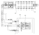
도 4는 본 발명에 따른 플라즈마 발생장치를 구비한 수처리 시스템의 평면도이다.1 is a cross-sectional view of a plasma generating apparatus according to the present invention,
2 and 3 are side views of a water treatment system having a plasma generating device according to the present invention, and Fig.
4 is a plan view of a water treatment system having a plasma generating device according to the present invention.
이하, 첨부 도면을 참조하여 본 발명의 실시예를 보다 상세하게 설명하고자 한다. 이에 앞서, 본 명세서 및 청구범위에 사용된 용어나 단어는 통상적이거나 사전적인 의미로 한정하여 해석되어서는 아니 되며, 발명자는 그 자신의 발명을 가장 최선의 방법으로 설명하기 위해 용어의 개념을 적절하게 정의할 수 있다는 원칙에 입각하여, 본 발명의 기술적 사상에 부합하는 의미와 개념으로 해석되어야만 한다.Hereinafter, embodiments of the present invention will be described in detail with reference to the accompanying drawings. Prior to this, terms and words used in the present specification and claims should not be construed as limited to ordinary or dictionary terms, and the inventor should appropriately interpret the concept of the term appropriately in order to describe its own invention in the best way. The present invention should be construed in accordance with the meaning and concept consistent with the technical idea of the present invention.
따라서, 본 명세서에 기재된 실시예와 도면에 도시된 구성은 본 발명의 가장 바람직한 일실시예에 불과할 뿐이고 본 발명의 기술적 사상을 모두 대변하는 것은 아니므로, 본 출원시점에 있어서 이들을 대체할 수 있는 다양한 균등물과 변형예들이 있을 수 있음을 이해하여야 한다.Therefore, the embodiments described in this specification and the configurations shown in the drawings are merely the most preferred embodiments of the present invention and do not represent all the technical ideas of the present invention. Therefore, It is to be understood that equivalents and modifications are possible.
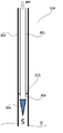
도 1은 본 발명에 따른 플라즈마 발생장치의 단면도이다.1 is a cross-sectional view of a plasma generating apparatus according to the present invention.
도 1에 도시된 바와 같이 본 발명에 따른 플라즈마 발생장치는 내부전극(311), 유전체관(312), 가스배출구(313), 및 방전침(314)을 포함한다.1, the plasma generating apparatus according to the present invention includes an
상기 내부전극(311)은 전원공급장치에서 직류전원 또는 교류전원이 공급됨에 따라 접지전극과의 전위차로 인해 플라즈마를 발생시킨다.The
또한, 상기 내부전극(311)은 내부가 중공된 원통형 구조로 이루어져 상부 일단에서 방전가스가 주입되면, 해당 가스가 중공된 부분을 통해 이동된다.The
상기 유전체관(312)은 상기 내부전극(311)과 마찬가지로 원통형으로 형성되되, 상기 내부전극(311) 보다 큰 반경을 가지면서, 상기 내부전극(311)의 외주면과 소정간격만큼 이격되게 형성된다.The
이때, 상기 유전체관(312)은 석영 물질로 이루어지는 것이 바람직하고, 그외 절연물질인 강화유리, 테프론 등으로도 이루어질 수 있다.At this time, the
또한, 이때 상기 유전체관(312)은 상기 방전침(314)보다 길게 형성되어 방전공간'S'을 확보하는 것이 바람직하다.At this time, it is preferable that the
상기 가스 배출구(313)는 상기 내부전극(311)의 하부 타단에서 소정 높이에 복수개가 형성되어 상기 내부전극(311)의 중공된 부분을 통해 이동한 방전가스를 배출시킨다.A plurality of
한편, 상기 방전침(314)은 상기 내부전극(311)의 말단부에 뾰족하게 형성되어 고밀도의 플라즈마를 발생시킨다.The
이때, 상기 방전침(314)은 플라즈마 발생효율이 향상될 수 있도록 텅스텐 물질로 이루어지는 것이 바람직하고, 그외 몰리브덴, 니켈, 백금 또는, 니켈, 몰리브텐 구리 등과 같이 내열성과 내산성 및 도전성이 우수한 합금으로도 이루어질 수 있다.At this time, the
또한, 상기 방전침(314)은 보다 고밀도의 플라즈마를 발생시키기 위하여 동일한 구조로 복수개가 형성되거나, 단차진 구조를 가져 복수의 뾰족한 침이 형성되는 구조일 수 있는 것이 바람직하다.In addition, the
상기 전원공급장치에서 전원이 접지전극과 상기 내부전극(311)에 공급되면, 상기 내부전극(311)과 상기 접지전극 사이에 플라즈마가 발생하게 되는데, 이때 상기 접지전극은 물이 된다.When power is supplied from the power supply unit to the ground electrode and the
상술한 바와 같은 구성을 갖는 본 발명에 따른 플라즈마 발생장치는 전원공급장치에서 전원이 공급됨에 따라 상기 내부전극(311)과 접지전극(물) 사이의 전위차에 의해 공간`S`에서 플라즈마가 발생되어 물을 살균시킨다.In the plasma generating apparatus according to the present invention having the above-described configuration, as power is supplied from the power supply device, a plasma is generated in the space `S` by a potential difference between the
한편, 상기 내부전극(311)의 외경과 상기 유전체관(312)의 내경 사이로 물이 유입되는 것을 방지하기 위하여, 상기 내부전극(311)과 상기 유전체관(312)사이의 상기 가스 배출구(313) 상부에 차단막(315)이 더 형성되는 것이 바람직하다.The
상기 차단막(315)은 상기 내부전극(311)과 상기 유전체관(312) 사이로 유입된 물이 전원공급장치 등 기타 장치로 전달되어 부식과 그에 따른 고장, 그리고 그외 물의 유입을 원인으로 해서 발생할 수 있는 고장을 방지한다.The
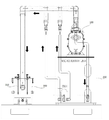
이하에서, 도 2 및 도 3을 참조하여 상술한 바와 같은 구성을 갖는 본 발명에 따른 플라즈마 발생장치를 구비한 수처리 시스템에 대하여 설명한다.Hereinafter, a water treatment system having a plasma generating apparatus according to the present invention having the above-described configuration with reference to Figs. 2 and 3 will be described.
도 2, 도 3, 및 도 4에 도시된 바와 같이, 본 발명에 따른 플라즈마 발생장치를 구비한 수처리 시스템은 펌프(100), 버블조(200), 및 살균조(300)를 포함한다.2, 3, and 4, the water treatment system having the plasma generating apparatus according to the present invention includes a
상기 펌프(100)는 강, 호수, 또는 바다에서 담수 또는 해수와 같은 물을 끌어올려, 물의 일부를 버블조(200)로 보내고, 나머지 일부를 살균조(300)로 보낸다.The
상기 버블조(200)는 상기 펌프(100)에서 보내지는 오염된 물을 수용한 후 기포를 발생시켜 용존산소량을 높여주거나, 유막을 제거해 준다.The
한편, 상기 버블조(200)에서 버블링되어 용존산소량이 증가되고 유막이 제거된 물과 상기 펌프(100)에서 살균조(300)로 전달되는 물은 소정위치에서 합류한 후, 상기 살균조(300)로 유입된다.On the other hand, the water in which the amount of dissolved oxygen is increased by the bubbling in the
도 3 및 도 4에 도시된 바와 같이, 상기 살균조(300)는 이미 상세히 설명한 본 발명에 따른 플라즈마 발생장치(310)를 복수개 포함하여, 전원공급장치에서 플라즈마 발생장치(310)로 전원이 공급됨에 따라 플라즈마가 발생되어 유입된 물을 살균처리한다.3 and 4, the sterilizing
즉, 상기 살균조(300)는 상기 플라즈마 발생을 통해 강력한 산화력을 가진 OH 라디컬의 생성을 촉진시켜 오존, 과산화수소, 자외선 등을 결합시켜 오염된 물을 정수할 수 있다.That is, the sterilizing
상기 살균조(300)에서 살균처리된 물은 어패류가 있는 양식장으로 공급되거나, 예비탱크 등에 공급되어 저장된다.The sterilized water in the
이상과 같이, 본 발명은 비록 한정된 실 시예와 도면에 의해 설명되었으나, 본 발명은 이것에 의해 한정되지 않으며 본 발명이 속하는 기술분야에서 통상의 지식을 가진 자에 의해 본 발명의 기술 사상과 하기에 기재될 청구범위의 균등 범위 내에서 다양한 수정 및 변형이 가능함은 물론이다. While the present invention has been particularly shown and described with reference to exemplary embodiments thereof, it is to be understood that the invention is not limited to the disclosed embodiments, but, on the contrary, It is to be understood that various modifications and changes may be made without departing from the scope of the appended claims.
100 : 펌프
200 : 버블조
300 : 살균조
310 : 플라즈마 발생장치
311 : 내부전극
312 : 유전체관
313 : 가스배출구
314 : 방전침
315 : 차단막100: pump
200: bubble tank
300: sterilization tank
310: Plasma generator
311: internal electrode
312: dielectric tube
313: gas outlet
314: Discharge needle
315:
Claims (7)
상기 내부전극(311)의 외주면과 소정간격만큼 이격되게 형성된 유전체관(312);
상기 내부전극(311)의 하부 타단에서 소정 높이에 복수개가 형성되어 상기 방전가스를 배출시키는 가스 배출구(313); 및
상기 내부전극(311)의 말단부에 형성된 방전침(314);를 포함하는 것을 특징으로 하는 플라즈마 발생장치.
An internal electrode (311) having a hollow structure inside and through which a discharge gas injected at an upper end is moved;
A dielectric tube 312 spaced apart from the outer circumferential surface of the inner electrode 311 by a predetermined distance;
A gas discharge port (313) formed at a predetermined height on the lower end of the internal electrode (311) to discharge the discharge gas; And
And a discharge needle (314) formed at a distal end of the internal electrode (311).
상기 가스 배출구(313) 상부의 상기 내부전극(311)과 상기 유전체관(312)사이에 형성된 차단막(315);을 더 포함하는 것을 특징으로 하는 플라즈마 발생장치.
The method according to claim 1,
And a blocking layer (315) formed between the internal electrode (311) and the dielectric tube (312) above the gas outlet (313).
상기 유전체관(312)은
상기 방전침(314)의 말단 보다 길게 형성되어 방전공간(S)을 확보하는 것을 특징으로 하는 플라즈마 발생장치.
The method according to claim 1,
The dielectric tube 312
Is formed longer than the end of the discharge needle (314) to secure the discharge space (S).
상기 방전침(314)은 뾰족한 침 구조로 형성되는 것을 특징으로 하는 플라즈마 발생장치.
The method according to claim 1,
Wherein the discharge needle (314) is formed with a pointed needle structure.
상기 방전침(314)은 텅스텐 물질로 이루어진 것을 특징으로 하는 플라즈마 발생장치.
5. The method of claim 4,
Wherein the discharge needle (314) is made of a tungsten material.
전원공급장치에서 전원이 공급됨에 따라 상기 내부전극(311)과 접지전극(물) 사이의 전위차에 의해 방전공간(S)에서 플라즈마가 발생하는 것을 특징으로 하는 플라즈마 발생장치.
The method according to claim 1,
Wherein plasma is generated in the discharge space (S) by a potential difference between the internal electrode (311) and the ground electrode (water) as power is supplied from the power supply device.
상기 펌프(100)에서 물의 일부를 공급받아 해당 물에 용존산소량을 증가시키고 유막을 제거하는 버블조(200); 및
제 1항 내지 제6항 중 어느 한 항의 플라즈마 발생장치를 복수개 구비하여 상기 펌프(200)와 상기 버블조(200)에서 유입된 물에 플라즈마를 발생시켜 살균처리하는 살균조(300);를 포함하는 것을 특징으로 하는 플라즈마 발생장치를 구비한 수처리 시스템.A pump 100 for introducing water;
A bubble tank 200 for receiving a part of water from the pump 100 to increase the amount of dissolved oxygen in the water and removing the oil film; And
A sterilizing tank (300) having a plurality of plasma generating apparatuses according to any one of claims 1 to 6 for generating plasma in the water introduced from the pump (200) and the bubble bath (200) And a plasma generating device for generating plasma.
Priority Applications (1)
| Application Number | Priority Date | Filing Date | Title |
|---|---|---|---|
| KR1020170024713A KR20180098435A (en) | 2017-02-24 | 2017-02-24 | Plasma generating device and water purification system equipped therewith |
Applications Claiming Priority (1)
| Application Number | Priority Date | Filing Date | Title |
|---|---|---|---|
| KR1020170024713A KR20180098435A (en) | 2017-02-24 | 2017-02-24 | Plasma generating device and water purification system equipped therewith |
Related Child Applications (1)
| Application Number | Title | Priority Date | Filing Date |
|---|---|---|---|
| KR1020190067448A Division KR102106879B1 (en) | 2019-06-07 | 2019-06-07 | Plasma generating device and water purification system equipped therewith |
Publications (1)
| Publication Number | Publication Date |
|---|---|
| KR20180098435A true KR20180098435A (en) | 2018-09-04 |
Family
ID=63598183
Family Applications (1)
| Application Number | Title | Priority Date | Filing Date |
|---|---|---|---|
| KR1020170024713A Ceased KR20180098435A (en) | 2017-02-24 | 2017-02-24 | Plasma generating device and water purification system equipped therewith |
Country Status (1)
| Country | Link |
|---|---|
| KR (1) | KR20180098435A (en) |
Cited By (3)
| Publication number | Priority date | Publication date | Assignee | Title |
|---|---|---|---|---|
| KR101984437B1 (en) | 2018-12-26 | 2019-05-30 | 김숙 | Water treating apparatus using plasma |
| CN114735783A (en) * | 2022-04-16 | 2022-07-12 | 西安交通大学 | Hollow needle liquid level plasma sterilization device utilizing quartz tube for flow guide |
| CN116059423A (en) * | 2023-02-13 | 2023-05-05 | 奥普家居股份有限公司 | Generating device and preparation method of active particle water mist aerosol |
Citations (1)
| Publication number | Priority date | Publication date | Assignee | Title |
|---|---|---|---|---|
| KR101056097B1 (en) | 2009-03-25 | 2011-08-10 | 박종훈 | Atmospheric Pressure Plasma Generator |
-
2017
- 2017-02-24 KR KR1020170024713A patent/KR20180098435A/en not_active Ceased
Patent Citations (1)
| Publication number | Priority date | Publication date | Assignee | Title |
|---|---|---|---|---|
| KR101056097B1 (en) | 2009-03-25 | 2011-08-10 | 박종훈 | Atmospheric Pressure Plasma Generator |
Cited By (4)
| Publication number | Priority date | Publication date | Assignee | Title |
|---|---|---|---|---|
| KR101984437B1 (en) | 2018-12-26 | 2019-05-30 | 김숙 | Water treating apparatus using plasma |
| CN114735783A (en) * | 2022-04-16 | 2022-07-12 | 西安交通大学 | Hollow needle liquid level plasma sterilization device utilizing quartz tube for flow guide |
| CN114735783B (en) * | 2022-04-16 | 2023-09-12 | 西安交通大学 | Hollow needle liquid level plasma sterilization device utilizing quartz tube for diversion |
| CN116059423A (en) * | 2023-02-13 | 2023-05-05 | 奥普家居股份有限公司 | Generating device and preparation method of active particle water mist aerosol |
Similar Documents
| Publication | Publication Date | Title |
|---|---|---|
| US7704401B2 (en) | Liquid treatment apparatus and liquid treatment method | |
| JP6008359B2 (en) | In-liquid plasma generation apparatus, liquid to be treated purification apparatus, and ion-containing liquid generation apparatus | |
| JP4813443B2 (en) | Water treatment equipment | |
| US20150136711A1 (en) | Liquid treatment apparatus and liquid treatment method | |
| KR101210558B1 (en) | Plasma water treatmant processing device | |
| JP6678338B2 (en) | Liquid treatment equipment | |
| US9969627B2 (en) | Liquid treatment apparatus and liquid treatment method | |
| JP6511440B2 (en) | Plasma irradiation method and plasma irradiation apparatus | |
| US9409800B2 (en) | Electric arc for aqueous fluid treatment | |
| KR101497591B1 (en) | Apparatus for treating water using discharge in reactor | |
| KR101923094B1 (en) | Ballast water treatment system with a low temperature water plasma device | |
| KR101479261B1 (en) | Water Feeder and Plasma Water Treatment Apparatus using the Same | |
| KR20180098435A (en) | Plasma generating device and water purification system equipped therewith | |
| KR20100095306A (en) | Active substance neutralizing apparatus using uv led and system for treatment of ballast water with the same | |
| SG183405A1 (en) | Ballast water treatment system using a highly efficient electrolysis device | |
| KR102106879B1 (en) | Plasma generating device and water purification system equipped therewith | |
| ES3009574T3 (en) | System and method for treatment of wastewater fluids | |
| RU2152359C1 (en) | Device for cleaning and decontamination of water by high-voltage electrical discharges | |
| JP2003340454A (en) | Plasma sterilizer and plasma sterilizer cooler | |
| KR101323258B1 (en) | plasma sterilization method | |
| US20160332892A1 (en) | Device and method for detoxifying plasma-treated water containing hydrogen peroxide | |
| KR20200041292A (en) | Water treatment device | |
| KR100304461B1 (en) | Apparatus cleaning water | |
| JP4461774B2 (en) | Water treatment equipment and water treatment equipment | |
| KR20160093218A (en) | Apparatus and method for removing contaminants using hydrogen peroxide and under water plazma dischare |
Legal Events
| Date | Code | Title | Description |
|---|---|---|---|
| A201 | Request for examination | ||
| PA0109 | Patent application |
Patent event code: PA01091R01D Comment text: Patent Application Patent event date: 20170224 |
|
| PA0201 | Request for examination | ||
| E902 | Notification of reason for refusal | ||
| PE0902 | Notice of grounds for rejection |
Comment text: Notification of reason for refusal Patent event date: 20180208 Patent event code: PE09021S01D |
|
| AMND | Amendment | ||
| E90F | Notification of reason for final refusal | ||
| PE0902 | Notice of grounds for rejection |
Comment text: Final Notice of Reason for Refusal Patent event date: 20180827 Patent event code: PE09021S02D |
|
| PG1501 | Laying open of application | ||
| E601 | Decision to refuse application | ||
| PE0601 | Decision on rejection of patent |
Patent event date: 20190304 Comment text: Decision to Refuse Application Patent event code: PE06012S01D Patent event date: 20180827 Comment text: Final Notice of Reason for Refusal Patent event code: PE06011S02I Patent event date: 20180208 Comment text: Notification of reason for refusal Patent event code: PE06011S01I |
|
| X091 | Application refused [patent] | ||
| AMND | Amendment | ||
| PX0901 | Re-examination |
Patent event code: PX09011S01I Patent event date: 20190304 Comment text: Decision to Refuse Application Patent event code: PX09012R01I Patent event date: 20180508 Comment text: Amendment to Specification, etc. |
|
| PX0601 | Decision of rejection after re-examination |
Comment text: Decision to Refuse Application Patent event code: PX06014S01D Patent event date: 20190507 Comment text: Amendment to Specification, etc. Patent event code: PX06012R01I Patent event date: 20190404 Comment text: Decision to Refuse Application Patent event code: PX06011S01I Patent event date: 20190304 Comment text: Final Notice of Reason for Refusal Patent event code: PX06013S02I Patent event date: 20180827 Comment text: Amendment to Specification, etc. Patent event code: PX06012R01I Patent event date: 20180508 Comment text: Notification of reason for refusal Patent event code: PX06013S01I Patent event date: 20180208 |
|
| X601 | Decision of rejection after re-examination | ||
| A107 | Divisional application of patent | ||
| PA0107 | Divisional application |
Comment text: Divisional Application of Patent Patent event date: 20190607 Patent event code: PA01071R01D |