KR20180117536A - Vibrating type linear actuator and cutting device - Google Patents
Vibrating type linear actuator and cutting device Download PDFInfo
- Publication number
- KR20180117536A KR20180117536A KR1020180041070A KR20180041070A KR20180117536A KR 20180117536 A KR20180117536 A KR 20180117536A KR 1020180041070 A KR1020180041070 A KR 1020180041070A KR 20180041070 A KR20180041070 A KR 20180041070A KR 20180117536 A KR20180117536 A KR 20180117536A
- Authority
- KR
- South Korea
- Prior art keywords
- movable body
- linear actuator
- weight
- output
- magnet
- Prior art date
- Legal status (The legal status is an assumption and is not a legal conclusion. Google has not performed a legal analysis and makes no representation as to the accuracy of the status listed.)
- Granted
Links
Images
Classifications
-
- H—ELECTRICITY
- H02—GENERATION; CONVERSION OR DISTRIBUTION OF ELECTRIC POWER
- H02K—DYNAMO-ELECTRIC MACHINES
- H02K33/00—Motors with reciprocating, oscillating or vibrating magnet, armature or coil system
- H02K33/18—Motors with reciprocating, oscillating or vibrating magnet, armature or coil system with coil systems moving upon intermittent or reversed energisation thereof by interaction with a fixed field system, e.g. permanent magnets
-
- H—ELECTRICITY
- H02—GENERATION; CONVERSION OR DISTRIBUTION OF ELECTRIC POWER
- H02K—DYNAMO-ELECTRIC MACHINES
- H02K5/00—Casings; Enclosures; Supports
- H02K5/24—Casings; Enclosures; Supports specially adapted for suppression or reduction of noise or vibrations
-
- B—PERFORMING OPERATIONS; TRANSPORTING
- B26—HAND CUTTING TOOLS; CUTTING; SEVERING
- B26B—HAND-HELD CUTTING TOOLS NOT OTHERWISE PROVIDED FOR
- B26B19/00—Clippers or shavers operating with a plurality of cutting edges, e.g. hair clippers, dry shavers
- B26B19/02—Clippers or shavers operating with a plurality of cutting edges, e.g. hair clippers, dry shavers of the reciprocating-cutter type
-
- B—PERFORMING OPERATIONS; TRANSPORTING
- B26—HAND CUTTING TOOLS; CUTTING; SEVERING
- B26B—HAND-HELD CUTTING TOOLS NOT OTHERWISE PROVIDED FOR
- B26B19/00—Clippers or shavers operating with a plurality of cutting edges, e.g. hair clippers, dry shavers
- B26B19/28—Drive layout for hair clippers or dry shavers, e.g. providing for electromotive drive
- B26B19/282—Motors without a rotating central drive shaft, e.g. linear motors
-
- B—PERFORMING OPERATIONS; TRANSPORTING
- B26—HAND CUTTING TOOLS; CUTTING; SEVERING
- B26B—HAND-HELD CUTTING TOOLS NOT OTHERWISE PROVIDED FOR
- B26B19/00—Clippers or shavers operating with a plurality of cutting edges, e.g. hair clippers, dry shavers
- B26B19/28—Drive layout for hair clippers or dry shavers, e.g. providing for electromotive drive
- B26B19/288—Balance by opposing oscillation
-
- H—ELECTRICITY
- H02—GENERATION; CONVERSION OR DISTRIBUTION OF ELECTRIC POWER
- H02K—DYNAMO-ELECTRIC MACHINES
- H02K33/00—Motors with reciprocating, oscillating or vibrating magnet, armature or coil system
- H02K33/02—Motors with reciprocating, oscillating or vibrating magnet, armature or coil system with armatures moved one way by energisation of a single coil system and returned by mechanical force, e.g. by springs
- H02K33/04—Motors with reciprocating, oscillating or vibrating magnet, armature or coil system with armatures moved one way by energisation of a single coil system and returned by mechanical force, e.g. by springs wherein the frequency of operation is determined by the frequency of uninterrupted AC energisation
- H02K33/06—Motors with reciprocating, oscillating or vibrating magnet, armature or coil system with armatures moved one way by energisation of a single coil system and returned by mechanical force, e.g. by springs wherein the frequency of operation is determined by the frequency of uninterrupted AC energisation with polarised armatures
-
- H—ELECTRICITY
- H02—GENERATION; CONVERSION OR DISTRIBUTION OF ELECTRIC POWER
- H02K—DYNAMO-ELECTRIC MACHINES
- H02K33/00—Motors with reciprocating, oscillating or vibrating magnet, armature or coil system
- H02K33/16—Motors with reciprocating, oscillating or vibrating magnet, armature or coil system with polarised armatures moving in alternate directions by reversal or energisation of a single coil system
-
- H—ELECTRICITY
- H02—GENERATION; CONVERSION OR DISTRIBUTION OF ELECTRIC POWER
- H02K—DYNAMO-ELECTRIC MACHINES
- H02K16/00—Machines with more than one rotor or stator
- H02K16/02—Machines with one stator and two or more rotors
-
- H—ELECTRICITY
- H02—GENERATION; CONVERSION OR DISTRIBUTION OF ELECTRIC POWER
- H02K—DYNAMO-ELECTRIC MACHINES
- H02K7/00—Arrangements for handling mechanical energy structurally associated with dynamo-electric machines, e.g. structural association with mechanical driving motors or auxiliary dynamo-electric machines
-
- H—ELECTRICITY
- H02—GENERATION; CONVERSION OR DISTRIBUTION OF ELECTRIC POWER
- H02K—DYNAMO-ELECTRIC MACHINES
- H02K7/00—Arrangements for handling mechanical energy structurally associated with dynamo-electric machines, e.g. structural association with mechanical driving motors or auxiliary dynamo-electric machines
- H02K7/04—Balancing means
Landscapes
- Engineering & Computer Science (AREA)
- Life Sciences & Earth Sciences (AREA)
- Forests & Forestry (AREA)
- Mechanical Engineering (AREA)
- Power Engineering (AREA)
- Dry Shavers And Clippers (AREA)
- Reciprocating, Oscillating Or Vibrating Motors (AREA)
- Apparatuses For Generation Of Mechanical Vibrations (AREA)
Abstract
Description
본 발명은 1축 방향으로 왕복 이동하는 진동형 리니어 액추에이터 및 상기 진동형 리니어 액추에이터를 구비하고, 체모나 풀 등의 대상물을 절단하는 절단 장치에 관한 것이다.The present invention relates to a vibration type linear actuator reciprocally moving in a uniaxial direction and a cutting device having the vibration type linear actuator and cutting an object such as a hair or a pool.
1축 방향으로 왕복 이동하는 진동형 리니어 액추에이터, 특히 인간의 손에 파지되는 장치에 있어서는, 손에 전달되는 진동을 억제하기 위해, 중량이 거의 동일하고 또한 서로 역위상으로 구동되는 2종의 가동체가 평행하게 병설되는 경우가 있다. 또한, 이들 2종의 가동체가 서로 연결되며, 한쪽의 가동체에만 체모 등의 대상물을 절단하기 위한 가동날이 설치된 구조가 특허문헌(일본 특허 공개 제2005-185067호 공보)에 개시되어 있다.In order to suppress vibrations transmitted to a hand, in a vibrating linear actuator reciprocally moving in a uniaxial direction, in particular, in a device held in a human hand, two kinds of movable members, which are almost identical in weight and driven in opposite phases, In some cases. In addition, a structure in which these two kinds of movable members are connected to each other and a movable blade for cutting an object such as a hair curler is provided only on one movable member is disclosed in Patent Document (Japanese Patent Application Laid-Open No. 2005-185067).
그런데, 상기와 같은 진동형 리니어 액추에이터는, 한쪽의 가동체만이 대상물에 대하여 작용하는 것임에도 불구하고, 진동 억제를 위해 동일 중량의 가동체를 역위상으로 진동시키고 있어, 에너지를 불필요하게 소비하고 있다.However, although the vibrating linear actuator as described above vibrates in the opposite phase to the moving body of the same weight in order to suppress the vibration, even though only one moving body acts on the object, energy is unnecessarily consumed .
본 발명은 상기의 종래의 문제점을 감안하여 이루어진 것이며, 그 목적으로 하는 바는, 진동을 억제하면서, 대상물에 작용하는 출력 가동체에 진동형 리니어 액추에이터의 추력을 집중시켜 파워풀한 구동을 실현할 수 있는 진동형 리니어 액추에이터, 및, 진동형 리니어 액추에이터를 구비한 절단 장치를 제공하는 것에 있다.SUMMARY OF THE INVENTION The present invention has been made in view of the above-mentioned conventional problems, and an object thereof is to provide a vibration type linear actuator capable of realizing powerful driving by concentrating thrust of a vibrating linear actuator on an output movable body, A linear actuator, and a vibration type linear actuator.
상기 목적을 달성하기 위해, 본 발명의 하나인 진동형 리니어 액추에이터는, 주기적으로 변동하는 자계에 의해 왕복 이동하여, 대상물에 작용하는 출력 가동체와, 상기 출력 가동체와 역위상으로 왕복 이동하여, 진동을 억제하는 흡진 가동체를 구비하는 진동형 리니어 액추에이터로서, 상기 흡진 가동체의 중량은, 상기 출력 가동체의 중량보다도 가벼운 것을 특징으로 하고 있다.In order to achieve the above object, one aspect of the present invention is an oscillatory linear actuator comprising: an output movable body that reciprocates by a periodically varying magnetic field and acts on an object; Wherein the weight of the absorbing movable body is lighter than the weight of the output movable body.
이것에 따르면, 대상물에는 작용하지 않는 흡진 가동체의 구동에 의해 진동형 리니어 액추에이터의 추력이 그다지 감소되지 않기 때문에, 에너지를 효율적으로 사용할 수 있다.According to this, since the thrust of the vibratory linear actuator is not reduced so much by the driving of the absorptive moving body which does not act on the object, energy can be efficiently used.
이상의 결과, 진동형 리니어 액추에이터는, 에너지를 효율적으로 사용할 수 있고, 또한 추력도 향상시킬 수 있기 때문에 파워풀한 구동을 실현할 수 있다.As a result, the vibratory linear actuator can use energy efficiently, and also can improve the thrust, thereby realizing powerful driving.
또한, 상기 흡진 가동체는, 중량 조절용의 추를 구비해도 된다.Further, the absorbing movable body may be provided with a weight for weight control.
이에 의해, 출력 가동체와 흡진 가동체의 중량 조정을 용이하게 행하는 것이 가능해진다.This makes it easy to adjust the weight of the output movable body and the absorbing movable body.
또한, 상기 출력 가동체 및 상기 흡진 가동체는, 영구 자석을 각각 구비하고, 고정된 하나의 전자석에 의해 왕복 이동하는 것으로 해도 된다.Further, the output movable member and the absorbing movable member may each include a permanent magnet, and may be reciprocally moved by a single fixed electromagnet.
또한, 본 발명의 다른 하나인 절단 장치는, 상기 진동형 리니어 액추에이터와, 상기 출력 가동체가 구비하는 가동날과, 상기 가동날과 맞스치는 고정날을 구비한다.In another aspect of the present invention, the cutting apparatus includes the vibrating linear actuator, a movable blade provided in the output movable body, and a fixed blade that is in contact with the movable blade.
본 발명에 따르면, 흡진 가동체에 진동형 리니어 액추에이터의 추력을 그다지 사용하지 않고, 출력되는 추력을 향상시킬 수 있다.According to the present invention, it is possible to improve the output thrust without using the thrust of the vibrating linear actuator as much as the suction movable body.
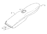
도 1은 실시 형태에 따른 진동형 리니어 액추에이터를 구비하고, 체모를 처리하는 절단 장치의 외관을 도시하는 사시도.
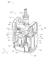
도 2는 실시 형태에 따른 진동형 리니어 액추에이터의 개략 구성을 도시하는 사시도.
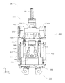
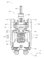
도 3은 실시 형태에 따른 진동형 리니어 액추에이터의 개략 구성을 도시하는 정면도.
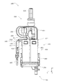
도 4는 실시 형태에 따른 진동형 리니어 액추에이터의 개략 구성을 도시하는 측면도.
도 5는 실시 형태에 따른 진동형 리니어 액추에이터의 개략 구성을 도시하는 배면도.
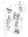
도 6은 실시 형태에 따른 진동형 리니어 액추에이터의 개략 구성을 도시하는 분해 사시도.
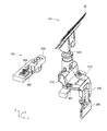
도 7은 실시 형태에 따른 출력 가동체 및 흡진 가동체의 개략 구성을 각각 도시하는 사시도.1 is a perspective view showing an appearance of a cutting device for processing hairs with a vibratory linear actuator according to an embodiment;
2 is a perspective view showing a schematic configuration of a vibration type linear actuator according to an embodiment;
3 is a front view showing a schematic configuration of a vibrating linear actuator according to the embodiment;
4 is a side view showing a schematic configuration of a vibrating linear actuator according to the embodiment;
5 is a rear view showing a schematic structure of a vibration type linear actuator according to the embodiment;
6 is an exploded perspective view showing a schematic configuration of a vibration type linear actuator according to the embodiment;
Fig. 7 is a perspective view showing a schematic structure of an output movable body and a suction movable body according to the embodiment; Fig.
다음에, 본 발명에 관한 진동형 리니어 액추에이터 및 진동형 리니어 액추에이터를 구비한 절단 장치의 실시 형태에 대하여, 도면을 참조하면서 설명한다. 또한, 이하의 실시 형태는, 본 발명에 관한 진동형 리니어 액추에이터 및 진동형 리니어 액추에이터를 구비한 절단 장치의 일례를 나타낸 것에 지나지 않는다. 따라서 본 발명은 이하의 실시 형태를 참고로 청구범위의 문언에 의해 범위가 획정되는 것이며, 이하의 실시 형태에만 한정되는 것은 아니다. 따라서, 이하의 실시 형태에 있어서의 구성 요소 중, 본 발명의 최상위 개념을 나타내는 독립 청구항에 기재되어 있지 않은 구성 요소에 대해서는, 본 발명의 과제를 달성하는 데 반드시 필요하지는 않지만, 보다 바람직한 형태를 구성하는 것으로서 설명된다.DETAILED DESCRIPTION OF THE PREFERRED EMBODIMENTS Next, embodiments of a vibrating linear actuator and vibrating linear actuator according to the present invention will be described with reference to the drawings. The following embodiments are merely illustrative of an example of a cutting apparatus provided with the vibrating linear actuator and vibrating linear actuator according to the present invention. Therefore, the scope of the present invention is defined by the words of the following claims with reference to the following embodiments, and the present invention is not limited to the following embodiments. Therefore, among the constituent elements in the following embodiments, the constituent elements which are not described in the independent claim that represents the highest concept of the present invention are not necessarily required for attaining the object of the present invention, .
또한, 도면은, 본 발명을 나타내기 위해 적절히 강조나 생략, 비율의 조정을 행한 모식적인 도면으로 되어 있어, 실제의 형상이나 위치 관계, 비율과는 상이한 경우가 있다.In addition, the drawings are schematic diagrams in which the emphasis, omission, and ratio adjustment are appropriately performed in order to show the present invention, and there are cases where they are different from actual shapes, positional relationships, and ratios.
[절단 장치][Cutting device]
도 1은 실시 형태에 따른 진동형 리니어 액추에이터를 구비하고, 체모를 처리하는 절단 장치의 외관을 도시하는 사시도이다.Fig. 1 is a perspective view showing the appearance of a cutting apparatus for processing body hair with a vibrating linear actuator according to an embodiment. Fig.
도 1에 도시한 바와 같이, 절단 장치(1)는 예를 들어 전동 이발기이며, 케이스(2)와, 블레이드 유닛(3)과, 스위치(4)를 구비하고 있다. 케이스(2)에는, 블레이드 유닛(3)을 구동하기 위한 진동형 리니어 액추에이터(100)(도 2 등 참조)가 수용되어 있다.As shown in Fig. 1, the
블레이드 유닛(3)은 케이스(2)의 선단 부분에 설치되어 있다. 블레이드 유닛(3)은 머리카락 등의 체모를 커트하는 역할을 갖는다. 구체적으로는, 블레이드 유닛(3)은 고정날(31) 및 가동날(32)을 구비하고 있다. 고정날(31)은 케이스(2)의 선단 부분에 고정되어 있다. 가동날(32)은 진동형 리니어 액추에이터(100)의 출력 가동체(101)의 축부(520)(도 2 등 참조)에 접속되어 있고, 후술하는 출력 가동체(101)의 일부에 포함되어 있다. 또한, 고정날(31) 및 가동날(32)은 대향하는 면에서 서로 접촉하고 있다. 가동날(32)은 진동형 리니어 액추에이터(100)에 의해, 고정날(31)에 대하여 왕복 운동한다. 이 왕복 이동에 의해 블레이드 유닛(3)이 머리카락을 커트한다.The blade unit (3) is provided at the tip end portion of the case (2). The
[진동형 리니어 액추에이터][Vibratory Linear Actuator]
다음에, 진동형 리니어 액추에이터(100)에 대하여 상세하게 설명한다.Next, the vibratory
도 2는 실시 형태에 따른 진동형 리니어 액추에이터의 개략 구성을 도시하는 사시도이다.2 is a perspective view showing a schematic structure of a vibrating linear actuator according to the embodiment.
도 3은 실시 형태에 따른 진동형 리니어 액추에이터의 개략 구성을 도시하는 정면도이다.3 is a front view showing a schematic configuration of a vibrating linear actuator according to the embodiment.
도 4는 실시 형태에 따른 진동형 리니어 액추에이터의 개략 구성을 도시하는 측면도이다.4 is a side view showing a schematic configuration of a vibration type linear actuator according to the embodiment.
도 5는 실시 형태에 따른 진동형 리니어 액추에이터의 개략 구성을 도시하는 배면도이다.5 is a rear view showing a schematic structure of a vibrating linear actuator according to the embodiment.
도 6은 실시 형태에 따른 진동형 리니어 액추에이터의 개략 구성을 도시하는 분해 사시도이다.Fig. 6 is an exploded perspective view showing a schematic structure of a vibrating linear actuator according to the embodiment.
도 7은 실시 형태에 따른 출력 가동체 및 흡진 가동체의 개략 구성을 각각 도시하는 사시도이다.Fig. 7 is a perspective view showing a schematic structure of the output movable body and the absorbing movable body according to the embodiment; Fig.
또한, 도면 중에 있어서, X축 방향을 출력 가동체 및 흡진 가동체의 진동 방향이라 하고, Y축 방향을 가동날(32)과 고정날(31)의 배열 방향이라 하고, Z축 방향을 출력 가동체의 연장 방향 축방향이라 한 3차원의 직교 좌표계로 각 부를 도시하고 있다. 또한, 사용 양태에 따라서는 Z축 방향이 상하 방향으로 되지 않는 경우도 생각되지만, 이하에서는 설명의 편의를 위해, XY 평면을 수평면으로, Z축 방향을 상하 방향으로 하여 설명하는 경우가 있다.In the drawings, the X-axis direction is referred to as a vibration direction of the output movable member and the absorbing movable member, the Y-axis direction is referred to as an arrangement direction of the
이들 도면(특히 도 6, 도 7)에 도시한 바와 같이, 진동형 리니어 액추에이터(100)는 출력 가동체(101)와, 흡진 가동체(102)와, 전자 코어 블록(200)과, 프레임(400)을 구비하고 있다.As shown in these figures (particularly Figs. 6 and 7), the oscillatory
[출력 가동체][Output actuation]
출력 가동체(101)는 주기적으로 변동하는 자계에 의해 왕복 이동하여, 체모 등의 대상물에 작용하는 부재이다. 본 실시 형태의 경우, 출력 가동체(101)는 가동날(32)과, 본체부(510)와, 제1 자석(301)과, 제1 요크(303)와, 제1 추(305)를 구비하고 있다.The output
본체부(510)는 출력 가동체(101)의 골격을 형성하는 구조 부재이며, 프레임(400)에 설치되는 부위이다. 본체부(510)는, 전체적으로 보아 크랭크 형상으로 굴곡되어 있고, XY 평면에 배치되는 설치부(512)와, Y축에 있어서 설치부(512)의 일단에 배치되며 Z축을 따라서 작용부(32)까지 연장되는 축부(520)와, 설치부(512)의 타단으로부터 Z축을 따라서 축부(520)와 반대로 향하여 연장되며, 제1 추(305)를 보유 지지하는 추 지지부(530)를 구비하고 있다.The
축부(520)의 선단부는, 대략 원기둥 형상(타원 기둥 형상)으로 되어 있고, 가동날(32)이 설치되는 부분이다.The distal end portion of the
추 지지부(530)는 설치부(512)에 대해 가동날(32)과의 균형을 맞추기 위해, 설치부(512)로부터 먼 위치에 제1 추(305)를 보유 지지하기 위한 부분이다.The
제1 자석(301)은 설치부(512)의 하방에 설치되는 영구 자석이다. 제1 자석(301)은 X축 방향에 있어서 한쪽의 단부가 N극, 다른 쪽의 단부가 S극으로 되어 있고, 전자 코어 블록(200)이 발생시키는 주기적으로 변동하는 자계의 작용에 의해 X축을 따라서 왕복 이동하여, 가동날(32)을 왕복 이동시키는 추력을 발생시키는 부재이다.The
제1 요크(303)는, 제1 자석(301)의 자속을 집중시켜 전자 코어 블록(200)으로부터 발생하는 자계와의 작용을 강화하는 자성체를 포함하는 부재이다.The
제1 추(305)는 제1 자석(301)에 대해 가동날(32)과 반대측의 위치에 설치되며, 출력 가동체(101)의 무게 중심의 위치를 조정하기 위한 부재이다.The
[흡진 가동체][Absorbing movable body]
흡진 가동체(102)는 출력 가동체(101)와 역위상으로 왕복 이동하여, 진동형 리니어 액추에이터(100) 전체의 진동을 억제하는 부재이다. 본 실시 형태의 경우, 흡진 가동체(102)는 접속부(309)와, 제2 자석(302)과, 제2 요크(304)와, 제2 추(306)를 구비하고 있다.The absorbing
접속부(309)는 흡진 가동체(102)의 골격을 형성하는 구조 부재이며, 프레임(400)에 설치되는 부위이다.The connecting
제2 자석(302)은 접속부(309)의 하방에 설치되는 영구 자석이다. 제2 자석(302)은 X축 방향에 있어서 한쪽의 단부가 S극, 다른 쪽의 단부가 N극으로 되어 있고, 제1 자석(301)과 극성이 반대로 되도록 배치되어 있다. 예를 들어, X축 방향에 있어서, 제1 자석(301)의 부측 단부가 N극, 정측 단부가 S극인 경우, 제2 자석(302)의 부측 단부가 S극, 정측 단부가 N극으로 되도록 배치한다. 제2 자석(302)은 제1 자석(301)과 마찬가지로, 전자 코어 블록(200)이 발생시키는 주기적으로 변동하는 자계의 작용에 의해 제1 자석(301)과 역위상으로 X축을 따라서 왕복 이동하는 부재이다.The
제2 요크(304)는, 제2 자석(302)의 자속을 집중시켜 전자 코어 블록(200)으로부터 발생하는 자계와의 작용을 강화하는 자성체를 포함하는 부재이다.The
제2 추(306)는 출력 가동체(101)와의 중량 밸런스를 조절하기 위한 부재이다.The
여기서, 흡진 가동체(102)의 중량, 본 실시 형태의 경우에는, 접속부(309), 제2 자석(302), 제2 요크(304), 제2 추(306) 및 체결 부재 등 일체로서 왕복 이동하는 부재(프레임(400)의 일부는 제외함)의 총 중량은, 출력 가동체(101)의 중량, 본 실시 형태의 경우, 본체부(510), 제1 자석(301), 제1 요크(303), 제1 추(305), 가동날(32) 및 체결 부재 등 일체로서 왕복 이동하는 부재(프레임(400)의 일부는 제외함)의 총 중량보다도 가볍게 되어 있다.Here, the weight of the absorptive
[전자 코어 블록][Electronic core block]
전자 코어 블록(200)은 출력 가동체(101)를 진동 방향(도면 중 X축 방향)으로 왕복 이동시키는 구동력을 발생시키는 장치이며, 코일 보빈(220)과, 코일(230)과, 코어(240)와, 기대(250)를 구비하고 있다. 또한 본 실시 형태의 경우, 전자 코어 블록(200)은 흡진 가동체(102)도 왕복 이동시키고 있다.The
코일(230)은 도전성의 선재를 나선 형상으로 감은 부재이며, 선재에 전류를 흘림으로써 자계를 발생시킬 수 있는 부재이다. 코일(230)에 교류적인 전류를 흘림으로써 발생하는 자계의 극성을 주기적으로 반복하여 반전시킬 수 있어, 출력 가동체(101) 및 흡진 가동체(102)를 왕복 이동시킬 수 있다.The
코일 보빈(220)은 도전성의 선재를 감아 코일을 형성하는 기체로 되는 부재이며, 본 실시 형태의 경우, 절연체에 의해 각통 형상으로 형성되어 있다.The
코어(240)는 자성체로 형성되며 코일(230) 내에서 발생한 자계를 소정의 위치로 유도하는 부재이다. 본 실시 형태의 경우, 코어(240)는 코일 보빈(220)에 관통되는 기둥부와 코일 보빈(220)의 양측에 병설되는 2개의 기둥부와 이들을 하단부에서 연결하는 기부를 일체로 구비한 측면에서 보아 E자 형상의 부재이다. 또한, 코어(240)의 형상은 E자 형상에 한정되는 것은 아니고, 예를 들어 U자 형상 등 임의의 형상을 채용할 수 있다.The
기대(250)는 예를 들어 절연체로 형성되어 있고, 코어(240) 및 코어(240)를 통해 코일 보빈(220)을 지지하는 부재이다. 기대(250)는 코어(240), 코일 보빈(220) 및 코일(230)을 프레임(400)에 대하여 소정의 위치에 보유 지지하는 부재이다.The
[프레임][frame]
프레임(400)은 출력 가동체(101) 및 흡진 가동체(102)를 이들의 왕복 이동을 허용하여 보유 지지하는 부재이다. 또한, 프레임(400)은 출력 가동체(101), 및, 흡진 가동체(102)와 전자 코어 블록(200)의 간극을 유지하는 부재이다. 본 실시 형태의 경우, 프레임(400)은 예를 들어 수지에 의해 일체 성형되어 있고, 출력 가동체(101)를 보유 지지하는 제1 보유 지지부(410)와, 흡진 가동체(102)를 보유 지지하는 제2 보유 지지부(420)와, 제1 보유 지지부(410) 및 제2 보유 지지부(420)를 연결하는 한 쌍의 연결 스프링(431, 432)과, 전자 코어 블록(200)을 보유 지지하는 제3 보유 지지부(440)를 구비하고 있다.The
제1 보유 지지부(410)는 X축 방향으로 장척의 제1 고정부(411)와, 제1 고정부(411)의 양단부로부터 현수되며, 제3 보유 지지부(440)에 연결된 한 쌍의 제1 스프링부(412)를 구비하고 있다.The
제1 고정부(411)에는, 출력 가동체(101)가 설치되어 있다. 본 실시 형태의 경우, 제1 고정부(411)에는, 하방으로부터 제1 자석(301), 제1 요크(303)의 순으로 설치되며, 상방에는 설치부(512)가 설치되어 있다. 또한 이들은 체결 부재(예를 들어 나사)로 체결되어 있다.In the
제2 보유 지지부(420)는 제1 고정부(411)에 병설되며, X축 방향으로 연장되는 장척 판 형상의 제2 고정부(421)와, 제2 고정부(421)의 양단부로부터 현수되며, 제3 보유 지지부(440)에 연결된 한 쌍의 제2 스프링부(422)를 구비하고 있다. 제2 보유 지지부(420)는 제1 보유 지지부(410)에 대하여 Y축 방향에서 인접하고 있다.The
제2 고정부(421)에는, 흡진 가동체(102)가 설치되어 있다. 본 실시 형태의 경우, 제2 고정부(421)에는, 하방으로부터 제2 자석(302), 제2 요크(304)의 순으로 설치되며, 상방에는 접속부(309) 및 제2 추(306)의 순으로 설치되어 있다.The
한 쌍의 연결 스프링(431)은 평평하게 만곡된 판 스프링이며, 제1 보유 지지부(410)와 제2 보유 지지부(420)를 요동 가능하게 연결하고 있다. 구체적으로는, 한 쌍의 연결 스프링(431) 중, 한쪽의 연결 스프링(431)은 제1 보유 지지부(410)의 제1 고정부(411)의 일단부와, 제2 보유 지지부(420)의 제2 고정부(421)의 일단부를 연결하고 있다. 또한, 다른 쪽의 연결 스프링(431)은 제1 보유 지지부(410)의 제1 고정부(411)의 타단부와, 제2 보유 지지부(420)의 제2 고정부(421)의 타단부를 연결하고 있다.The pair of connection springs 431 are plate springs that are curved in a flat manner, and the
또한, 연결 스프링(431)은 X축 방향에 있어서, 흡진 가동체(102)의 진폭은, 출력 가동체(101)의 진폭, 즉, 제2 고정부(421)의 진폭은, 제1 고정부(411)의 진폭보다도 넓어지는 것을 허용하는 구조를 구비하고 있다.The
제3 보유 지지부(440)는, 상면에서 보아 직사각형의 개구(441)를 갖는 프레임체이다. 이 제3 보유 지지부(440)의 개구(441)에 전자 코어 블록(200)이 삽입된 상태에서 전자 코어 블록(200)을 보유 지지하고 있다.The
그리고, 제3 보유 지지부(440)에는, 제1 보유 지지부(410)의 제1 스프링부(412)와, 제2 보유 지지부(420)의 제2 스프링부(422)가 연결되어 있다. 이 때문에, 제1 스프링부(412), 제2 스프링부(422)는 제3 보유 지지부(440)와의 연결 개소를 기점으로 하여 요동한다.The
[동작][action]
다음에, 진동형 리니어 액추에이터(100)의 동작에 대하여 설명한다.Next, the operation of the vibratory
전자석을 이루는 전자 코어 블록(200)의 코일(230)에 교류 전류가 공급되면, 코어(240)의 각 기둥부(242)의 선단면에서는, 배열순으로 N극, S극, N극의 상태와 S극, N극, S극의 상태가 주기적으로 교체된다.When AC current is supplied to the
한편, 제1 보유 지지부(410)에 의해 보유 지지된 제1 자석(301)과, 제2 보유 지지부(420)에 의해 보유 지지된 제2 자석(302)은, 서로의 극성이 반전되도록 배치되어 있다. 이 때문에, 하나의 코일(230)로부터 발생하는 자력에 의해 제1 자석(301), 제2 자석(302)에는, X축에 있어서 서로 반대 방향의 힘이 발생하여, 제1 자석(301)과 제2 자석(302)은 역방향으로 직선 이동한다. 이에 의해, 출력 가동체(101)와 흡진 가동체(102)는 역위상으로 진동한다.On the other hand, the
[효과 등][Effects, etc.]
이상과 같이, 본 실시 형태에 따른 절단 장치(1)에 구비되는 진동형 리니어 액추에이터(100)는 출력 가동체(101)에 대해, 흡진 가동체(102)의 중량이 가볍게 되도록 설정되어 있다. 따라서, 진동형 리니어 액추에이터(100)에 의해 발생하는 추력을 체모 등의 대상물의 절단에 기여하지 않는, 흡진 가동체(102)에 의해 감소시키지 않고, 추력을 대상물의 절단에 효율적으로 사용할 수 있다. 이 때문에, 진동형 리니어 액추에이터(100)의 추력을 효율적으로 출력 가동체(101)에 할당할 수 있어, 대상물을 파워풀하게 절단하는 것이 가능해진다.As described above, the vibration type
또한, 본 발명은 상기 실시 형태에 한정되는 것은 아니다. 예를 들어, 본 명세서에 있어서 기재한 구성 요소를 임의로 조합하여, 또한, 구성 요소의 몇 가지를 제외하여 실현되는 다른 실시 형태를 본 발명의 실시 형태로 해도 된다. 또한, 상기 실시 형태에 대하여 본 발명의 주지, 즉, 청구범위에 기재되는 문언이 나타내는 의미를 일탈하지 않는 범위에서 당업자가 생각해 내는 각종 변형을 실시하여 얻어지는 변형예도 본 발명에 포함된다.The present invention is not limited to the above-described embodiments. For example, other embodiments that are realized by arbitrarily combining the constituent elements described in this specification and excluding some of the constituent elements may be embodied in the embodiments of the present invention. The present invention also encompasses modifications of the above-described embodiments, which are obtained by carrying out various modifications contemplated by those skilled in the art without departing from the spirit of the present invention, that is, the meanings indicated by the words in the claims.
예를 들어, 출력 가동체(101)의 형상이나, 부품 구성은 상기 실시 형태에 한정되는 것은 아니다. 예를 들어 전자 코어 블록(200)이 영구 자석을 구비하는 경우, 출력 가동체(101)에 전자석이 설치되어 있어도 상관없다.For example, the shape and component configuration of the output
또한, 출력 가동체(101)는 가동날(32) 등의 작용체를 복수 구비하고 있어도 상관없다. 또한, 출력 가동체(101)가 복수로 분리되어 있었다고 해도 동일한 위상으로 일체로서 진동하여, 대상물에 작용하는 추력을 발생시키는 것이면 그것들은 출력 가동체(101)이다. 또한, 복수로 분리된 출력 가동체(101)의 중량 배분을 상이한 것으로 해도 되고, 출력 가동체(101) 전체로서의 중량이 흡진 가동체(102) 전체의 중량보다도 무거우면 된다.The output
또한, 출력 가동체(101)와 마찬가지로, 흡진 가동체(102)의 형상이나, 부품 구성은 상기 실시 형태에 한정되는 것은 아니고, 전자석을 구비하고 있어도 된다.Like the output
또한, 출력 가동체(101)는 가동날(32) 등의 작용체를 복수 구비하고 있어도 상관없다. 또한, 출력 가동체(101)가 복수로 분리되어 있었다고 해도 동일한 위상으로 일체로서 진동하여, 대상물에 작용하는 추력을 발생시키는 것은 출력 가동체(101)이다. 또한, 출력 가동체(101)와 역위상으로 진동하는 것이면 흡진 가동체(102)가 복수로 분리되어 있어도 된다.The output
또한, 흡진 가동체(102)가 전자 코어 블록(200)과의 작용에 의해 진동하는 것으로서 설명하였지만, 흡진 가동체(102)는 전자 코어 블록(200)으로부터 발생하는 자력과는 작용하지 않고, 출력 가동체(101)와 탄성 부재에 의해 접속된 동(動)흡진기로서 기능하는 것이어도 상관없다. 이 경우, 흡진 가동체(102)는 영구 자석 및 전자석을 구비하지 않아도 된다.Although the suction
본 발명은 전동 이발기, 전기 면도기 등에서 체모를 처리하는 절단 장치, 풀이나 나뭇가지를 절단하는 바리캉 등 절단 장치에 이용 가능하다.INDUSTRIAL APPLICABILITY The present invention can be applied to a cutting device such as an electric hair clipper, a cutting device for processing hairs in an electric shaver or the like, and a varicolum cutting device for cutting grass or branches.
1 : 절단 장치
2 : 케이스
3 : 블레이드 유닛
4 : 스위치
31 : 고정날
32 : 가동날
100 : 진동형 리니어 액추에이터
101 : 출력 가동체
102 : 흡진 가동체
200 : 전자 코어 블록
220 : 코일 보빈
230 : 코일
240 : 코어
242 : 기둥부
250 : 기대
301 : 제1 자석
302 : 제2 자석
303 : 제1 요크
304 : 제2 요크
305 : 제1 추
306 : 제2 추
309 : 접속부
400 : 프레임
410 : 제1 보유 지지부
411 : 제1 고정부
412 : 제1 스프링부
420 : 제2 보유 지지부
421 : 제2 고정부
422 : 제2 스프링부
431 : 연결 스프링
440 : 제3 보유 지지부
441 : 개구
510 : 본체부
512 : 설치부
520 : 축부
530 : 추 지지부1: Cutting device
2: Case
3: Blade unit
4: Switch
31: Fixed blade
32: movable blade
100: Vibrating linear actuator
101: Output movable body
102:
200: Electronic core block
220: Coil bobbin
230: Coil
240: Core
242:
250: Expectations
301: first magnet
302: second magnet
303: 1st yoke
304: second yoke
305: First Addition
306: 2nd Chu
309: Connection
400: frame
410: first holding member
411:
412: first spring portion
420: second holding member
421:
422: second spring portion
431: connecting spring
440: third holding member
441: opening
510:
512: Installation section
520: Shaft
530:
Claims (4)
상기 흡진 가동체의 중량은, 상기 출력 가동체의 중량보다도 가벼운 진동형 리니어 액추에이터.There is provided an oscillatory linear actuator including an output movable member that reciprocates by a periodically varying magnetic field to act on an object and a reciprocatingly reciprocating phase shift motor that suppresses vibration,
Wherein the weight of the absorbing movable body is lighter than the weight of the output movable body.
상기 흡진 가동체는, 중량 조절용의 추를 구비하는 진동형 리니어 액추에이터.The method according to claim 1,
Wherein the absorbing movable body has a weight for weight control.
상기 출력 가동체 및 상기 흡진 가동체는, 영구 자석을 각각 구비하고, 고정된 1개의 전자석에 의해 왕복 이동하는 진동형 리니어 액추에이터.3. The method according to claim 1 or 2,
Wherein the output movable member and the absorbing movable member are each provided with a permanent magnet and reciprocally moved by a fixed one electromagnet.
상기 출력 가동체가 구비하는 가동날과,
상기 가동날과 맞스치는 고정날을 구비하는 절단 장치.The vibration type linear actuator according to claim 1 or 2,
A movable blade provided on the output movable body,
And a fixed blade that abuts the movable blade.
Applications Claiming Priority (2)
| Application Number | Priority Date | Filing Date | Title |
|---|---|---|---|
| JP2017082980A JP6793367B2 (en) | 2017-04-19 | 2017-04-19 | Vibration type linear actuator and cutting device |
| JPJP-P-2017-082980 | 2017-04-19 |
Publications (2)
| Publication Number | Publication Date |
|---|---|
| KR20180117536A true KR20180117536A (en) | 2018-10-29 |
| KR102611699B1 KR102611699B1 (en) | 2023-12-11 |
Family
ID=61965730
Family Applications (1)
| Application Number | Title | Priority Date | Filing Date |
|---|---|---|---|
| KR1020180041070A Active KR102611699B1 (en) | 2017-04-19 | 2018-04-09 | Vibrating type linear actuator and cutting device |
Country Status (5)
| Country | Link |
|---|---|
| US (1) | US11235481B2 (en) |
| EP (1) | EP3393021B1 (en) |
| JP (1) | JP6793367B2 (en) |
| KR (1) | KR102611699B1 (en) |
| CN (1) | CN108880168B (en) |
Families Citing this family (8)
| Publication number | Priority date | Publication date | Assignee | Title |
|---|---|---|---|---|
| JP6793366B2 (en) * | 2017-04-19 | 2020-12-02 | パナソニックIpマネジメント株式会社 | Vibration type linear actuator and cutting device |
| JP6765079B2 (en) * | 2017-04-19 | 2020-10-07 | パナソニックIpマネジメント株式会社 | Vibration type linear actuator and hair treatment machine |
| WO2021252731A1 (en) | 2020-06-11 | 2021-12-16 | Andis Company | Hair clipper with linear actuator |
| CN114123702B (en) * | 2021-12-16 | 2023-03-21 | 广东辉达电器有限公司 | Brushless electromagnetic suspension vibrating motor |
| CN115816515B (en) * | 2022-12-26 | 2026-04-21 | 深圳术叶创新科技有限公司 | electric shaver |
| JP2024171134A (en) * | 2023-05-29 | 2024-12-11 | パナソニックIpマネジメント株式会社 | Vibration type linear actuator, structure for fixing vibration type linear actuator to fixed part, and cutting device |
| JP2024171120A (en) * | 2023-05-29 | 2024-12-11 | パナソニックIpマネジメント株式会社 | Vibration type linear actuator and cutting device |
| CN122341469A (en) * | 2023-11-06 | 2026-07-03 | 安迪思公司 | Hair cutter with magnetic drive component |
Citations (4)
| Publication number | Priority date | Publication date | Assignee | Title |
|---|---|---|---|---|
| JP2002199689A (en) * | 2000-09-29 | 2002-07-12 | Matsushita Electric Works Ltd | Linear oscillator |
| JP2003210493A (en) * | 2002-01-18 | 2003-07-29 | Matsushita Electric Works Ltd | electric toothbrush |
| KR20050063734A (en) * | 2003-12-22 | 2005-06-28 | 마츠시다 덴코 가부시키가이샤 | Linear oscillating actuator system |
| KR20050067048A (en) * | 2003-12-26 | 2005-06-30 | 마츠시다 덴코 가부시키가이샤 | Linear oscillating actuator |
Family Cites Families (11)
| Publication number | Priority date | Publication date | Assignee | Title |
|---|---|---|---|---|
| DE69501089T3 (en) * | 1994-03-28 | 2004-06-03 | Matsushita Electric Works, Ltd., Kadoma | Oscillating dry shaver |
| US5678312A (en) | 1994-10-31 | 1997-10-21 | Sanyo Electric Co., Ltd. | Electric shaver with reduced vibration |
| JPH08126785A (en) * | 1994-10-31 | 1996-05-21 | Sanyo Electric Co Ltd | Electric razor |
| EP1162721B1 (en) * | 2000-06-07 | 2005-12-21 | Matsushita Electric Works, Ltd. | Linear oscillating actuator |
| US6873067B2 (en) | 2000-09-29 | 2005-03-29 | Matsushita Electric Works, Ltd. | Linear oscillator |
| JP4099999B2 (en) * | 2002-01-30 | 2008-06-11 | 松下電工株式会社 | Hair cutter |
| JP3928495B2 (en) * | 2002-06-17 | 2007-06-13 | 松下電工株式会社 | Vibration type linear actuator |
| US7504751B2 (en) * | 2002-09-11 | 2009-03-17 | Braun Gmbh | Small electric appliance with a drive mechanism for generating an oscillatory motion |
| DE10242092A1 (en) * | 2002-09-11 | 2004-04-01 | Braun Gmbh | Small electrical device with a drive device for generating an oscillating movement |
| DE102006034050A1 (en) * | 2006-07-20 | 2008-01-24 | Braun Gmbh | Electric shaver |
| JP5945814B2 (en) | 2011-12-05 | 2016-07-05 | パナソニックIpマネジメント株式会社 | Linear actuator and oral hygiene device including the same |
-
2017
- 2017-04-19 JP JP2017082980A patent/JP6793367B2/en active Active
-
2018
- 2018-04-09 KR KR1020180041070A patent/KR102611699B1/en active Active
- 2018-04-10 EP EP18166438.4A patent/EP3393021B1/en active Active
- 2018-04-11 US US15/950,837 patent/US11235481B2/en active Active
- 2018-04-16 CN CN201810338414.3A patent/CN108880168B/en active Active
Patent Citations (5)
| Publication number | Priority date | Publication date | Assignee | Title |
|---|---|---|---|---|
| JP2002199689A (en) * | 2000-09-29 | 2002-07-12 | Matsushita Electric Works Ltd | Linear oscillator |
| JP2003210493A (en) * | 2002-01-18 | 2003-07-29 | Matsushita Electric Works Ltd | electric toothbrush |
| KR20050063734A (en) * | 2003-12-22 | 2005-06-28 | 마츠시다 덴코 가부시키가이샤 | Linear oscillating actuator system |
| JP2005185067A (en) * | 2003-12-22 | 2005-07-07 | Matsushita Electric Works Ltd | Vibration-type linear actuator and hair cutter provided with the same |
| KR20050067048A (en) * | 2003-12-26 | 2005-06-30 | 마츠시다 덴코 가부시키가이샤 | Linear oscillating actuator |
Also Published As
| Publication number | Publication date |
|---|---|
| EP3393021A1 (en) | 2018-10-24 |
| EP3393021B1 (en) | 2020-09-16 |
| US11235481B2 (en) | 2022-02-01 |
| KR102611699B1 (en) | 2023-12-11 |
| US20180304481A1 (en) | 2018-10-25 |
| JP2018176118A (en) | 2018-11-15 |
| JP6793367B2 (en) | 2020-12-02 |
| CN108880168B (en) | 2022-09-23 |
| CN108880168A (en) | 2018-11-23 |
Similar Documents
| Publication | Publication Date | Title |
|---|---|---|
| KR102611699B1 (en) | Vibrating type linear actuator and cutting device | |
| CN108736683B (en) | Vibrating Linear Actuator and Body Hair Processor | |
| JP6365190B2 (en) | Linear actuator and electric brush, electric cutting machine and electric air pump | |
| US7015602B2 (en) | Small electric appliance with a drive mechanism for generating an oscillatory motion | |
| EP1332843B1 (en) | Electric hair clipper | |
| KR102629397B1 (en) | Vibration type linear actuator and cutting device | |
| JP6803722B2 (en) | Linear vibration motor | |
| JP4679902B2 (en) | Small electric appliance with drive mechanism for generating oscillating motion | |
| US7504751B2 (en) | Small electric appliance with a drive mechanism for generating an oscillatory motion | |
| KR20180117535A (en) | Vibrating type linear actuator, hair handling machine, and method of manufacturing vibrating type linear actuator | |
| CA2994655C (en) | Actuator and electric beauty device | |
| JP5742860B2 (en) | Vibration generator | |
| US3505545A (en) | Polarized vibratory motor | |
| JP2024171120A (en) | Vibration type linear actuator and cutting device | |
| JP2005160134A (en) | Vibrating linear actuator |
Legal Events
| Date | Code | Title | Description |
|---|---|---|---|
| PA0109 | Patent application |
Patent event code: PA01091R01D Comment text: Patent Application Patent event date: 20180409 |
|
| PG1501 | Laying open of application | ||
| A201 | Request for examination | ||
| PA0201 | Request for examination |
Patent event code: PA02012R01D Patent event date: 20210308 Comment text: Request for Examination of Application Patent event code: PA02011R01I Patent event date: 20180409 Comment text: Patent Application |
|
| E701 | Decision to grant or registration of patent right | ||
| PE0701 | Decision of registration |
Patent event code: PE07011S01D Comment text: Decision to Grant Registration Patent event date: 20231115 |
|
| GRNT | Written decision to grant | ||
| PR0701 | Registration of establishment |
Comment text: Registration of Establishment Patent event date: 20231205 Patent event code: PR07011E01D |
|
| PR1002 | Payment of registration fee |
Payment date: 20231206 End annual number: 3 Start annual number: 1 |
|
| PG1601 | Publication of registration |