KR20190000006U - A target for measure the displacement in tunnel - Google Patents
A target for measure the displacement in tunnel Download PDFInfo
- Publication number
- KR20190000006U KR20190000006U KR2020170003233U KR20170003233U KR20190000006U KR 20190000006 U KR20190000006 U KR 20190000006U KR 2020170003233 U KR2020170003233 U KR 2020170003233U KR 20170003233 U KR20170003233 U KR 20170003233U KR 20190000006 U KR20190000006 U KR 20190000006U
- Authority
- KR
- South Korea
- Prior art keywords
- target
- tunnel
- vertical
- horizontal
- displacement measurement
- Prior art date
- Legal status (The legal status is an assumption and is not a legal conclusion. Google has not performed a legal analysis and makes no representation as to the accuracy of the status listed.)
- Ceased
Links
- 238000006073 displacement reaction Methods 0.000 title claims abstract description 48
- 238000005259 measurement Methods 0.000 claims abstract description 44
- 238000003780 insertion Methods 0.000 claims abstract description 24
- 230000037431 insertion Effects 0.000 claims abstract description 24
- 239000000463 material Substances 0.000 claims abstract description 14
- 229920003002 synthetic resin Polymers 0.000 claims abstract description 9
- 239000000057 synthetic resin Substances 0.000 claims abstract description 9
- 229920001971 elastomer Polymers 0.000 claims abstract description 7
- 239000005060 rubber Substances 0.000 claims abstract description 7
- 238000000034 method Methods 0.000 abstract description 10
- 239000004575 stone Substances 0.000 abstract description 8
- 238000005422 blasting Methods 0.000 abstract description 6
- 230000005641 tunneling Effects 0.000 abstract description 4
- 238000010276 construction Methods 0.000 description 4
- 238000009412 basement excavation Methods 0.000 description 3
- 238000013461 design Methods 0.000 description 3
- 239000002360 explosive Substances 0.000 description 2
- 230000001678 irradiating effect Effects 0.000 description 2
- 229920003051 synthetic elastomer Polymers 0.000 description 2
- 239000005061 synthetic rubber Substances 0.000 description 2
- 238000007796 conventional method Methods 0.000 description 1
- 230000004907 flux Effects 0.000 description 1
- 238000009434 installation Methods 0.000 description 1
- 238000004519 manufacturing process Methods 0.000 description 1
- 239000011435 rock Substances 0.000 description 1
- 230000035939 shock Effects 0.000 description 1
- 239000007779 soft material Substances 0.000 description 1
Images


Classifications
-
- G—PHYSICS
- G01—MEASURING; TESTING
- G01B—MEASURING LENGTH, THICKNESS OR SIMILAR LINEAR DIMENSIONS; MEASURING ANGLES; MEASURING AREAS; MEASURING IRREGULARITIES OF SURFACES OR CONTOURS
- G01B11/00—Measuring arrangements characterised by the use of optical techniques
- G01B11/16—Measuring arrangements characterised by the use of optical techniques for measuring the deformation in a solid, e.g. optical strain gauge
-
- G—PHYSICS
- G01—MEASURING; TESTING
- G01B—MEASURING LENGTH, THICKNESS OR SIMILAR LINEAR DIMENSIONS; MEASURING ANGLES; MEASURING AREAS; MEASURING IRREGULARITIES OF SURFACES OR CONTOURS
- G01B11/00—Measuring arrangements characterised by the use of optical techniques
- G01B11/002—Measuring arrangements characterised by the use of optical techniques for measuring two or more coordinates
-
- G—PHYSICS
- G01—MEASURING; TESTING
- G01C—MEASURING DISTANCES, LEVELS OR BEARINGS; SURVEYING; NAVIGATION; GYROSCOPIC INSTRUMENTS; PHOTOGRAMMETRY OR VIDEOGRAMMETRY
- G01C15/00—Surveying instruments or accessories not provided for in groups G01C1/00 - G01C13/00
- G01C15/02—Means for marking measuring points
- G01C15/06—Surveyors' staffs; Movable markers
-
- G—PHYSICS
- G01—MEASURING; TESTING
- G01C—MEASURING DISTANCES, LEVELS OR BEARINGS; SURVEYING; NAVIGATION; GYROSCOPIC INSTRUMENTS; PHOTOGRAMMETRY OR VIDEOGRAMMETRY
- G01C5/00—Measuring height; Measuring distances transverse to line of sight; Levelling between separated points; Surveyors' levels
-
- G—PHYSICS
- G01—MEASURING; TESTING
- G01D—MEASURING NOT SPECIALLY ADAPTED FOR A SPECIFIC VARIABLE; ARRANGEMENTS FOR MEASURING TWO OR MORE VARIABLES NOT COVERED IN A SINGLE OTHER SUBCLASS; TARIFF METERING APPARATUS; MEASURING OR TESTING NOT OTHERWISE PROVIDED FOR
- G01D11/00—Component parts of measuring arrangements not specially adapted for a specific variable
- G01D11/16—Elements for restraining, or preventing the movement of, parts, e.g. for zeroising
Landscapes
- Physics & Mathematics (AREA)
- General Physics & Mathematics (AREA)
- Engineering & Computer Science (AREA)
- Radar, Positioning & Navigation (AREA)
- Remote Sensing (AREA)
- Excavating Of Shafts Or Tunnels (AREA)
- Length Measuring Devices By Optical Means (AREA)
Abstract
본 고안은 터널 변위측정용 타겟에 관한 것으로, 더욱 상세하게는 타겟본체를 신축성이 우수한 연질합성수지나 고무재로서 "ㄴ"자 형태로 형성하며, 표적지가 부착되는 수직부의 양측면과 상면에는 수준기삽입홈을 형성한 뒤에, 터널에 터널 변위측정용 타겟을 설치하는 위치에 따라 수준기를 수준기삽입홈에 설치함으로서, 발파 등의 작업과정에서 날아오는 돌멩이 등의 부딪치는 경우에 수직부가 휘어졌다가 원위치로 탄력적으로 복귀함은 물론이고, 터널 변위측정용 타겟을 설치한 터널 내부면의 미세한 기울여짐까지 사전에 확인하여 붕괴사고 등의 안전사고를 예방할 수 있도록 하기 위한 것이다.
본 고안은 신축성이 우수한 연질합성수지재나 또는 고무재로서 "ㄴ"자 형태로 수직부(22)와 수평부(23)가 일체로 형성되어 타겟본체(21)가 형성되고, 수평부(23)에는 앙카볼트 설치용 볼트구멍(24)이 형성되며;
수직부(22)의 중앙에 표적지(25)가 부착되고, 표적지(25)가 부착되는 수직부(22)의 전면측에 수평방향과 수직방향에 수준기삽입홈(30)이 각각 형성되며, 터널 변위측정용 타겟(20)을 설치하는 터널의 내면 위치에 따라 수평 및 수직방향에 형성된 수준기삽입홈(30) 중의 어느 하나의 수준기삽입홈(30)에 1개의 수준기(31)를 설치하고;
상기 표적지(25)는 중앙에 야광부재로 타겟 중앙좌표점(29)이 형성되고, 타겟 중앙좌표점(29)을 중심으로 수직선(26)과 수평선(27), 그리고 동심원(28)이 표시되며, 상기 수직부(22)는 중앙부가 상하방향으로 두껍고 양측이 얇게 형성되는 구성이 포함되는 것을 특징으로 한다.The present invention relates to a target for measuring a tunnel displacement, and more particularly, to a target for a tunnel displacement measurement, which is formed of a soft synthetic resin or a rubber material having excellent stretchability in the form of "B", and on both sides and an upper surface, The level is set in the level insertion groove according to the position where the tunneling displacement measurement target is installed in the tunnel so that the vertical portion is bent when the stone or the like coming in the work process such as blasting collides, And it is also intended to prevent a safety accident such as a collapse accident by confirming a minute inclination of the inner surface of a tunnel provided with a tunnel displacement measurement target.
The present invention is characterized in that the vertical portion 22 and the horizontal portion 23 are integrally formed as a flexible synthetic resin material or rubber material having excellent elasticity to form a " Anchor bolt mounting bolt holes 24 are formed;
A leveling instrument insertion groove 30 is formed in the horizontal direction and the vertical direction on the front surface side of the vertical portion 22 to which the target 25 is attached and the tunnel 25 is attached to the center of the vertical portion 22, One leveling instrument (31) is provided in any leveling instrument insertion groove (30) of the leveling instrument insertion groove (30) formed in the horizontal and vertical directions in accordance with the inner surface position of the tunnel in which the displacement measurement target (20) is installed;
A target center coordinate point 29 is formed by a luminous member in the center of the target 25 and a vertical line 26, a horizontal line 27 and a concentric circle 28 are displayed around the target center coordinate point 29 , And the vertical part (22) is configured such that the central part is thick in the vertical direction and the both sides are formed thin.
Description
본 고안은 터널 변위측정용 타겟에 관한 것으로, 더욱 상세하게는 타겟본체를 신축성이 우수한 연질합성수지나 고무재로서 "ㄴ"자 형태로 형성하며, 표적지가 부착되는 수직부의 양측면과 상면에는 수준기삽입홈을 형성한 뒤에, 터널에 터널 변위측정용 타겟을 설치하는 위치에 따라 수준기를 수준기삽입홈에 설치함으로서, 발파 등의 작업과정에서 날아오는 돌멩이 등의 부딪치는 경우에 수직부가 휘어졌다가 원위치로 탄력적으로 복귀함은 물론이고, 터널 변위측정용 타겟을 설치한 터널 내부면의 미세한 기울여짐까지 사전에 확인하여 붕괴사고 등의 안전사고를 예방할 수 있도록 하기 위한 것이다.The present invention relates to a target for measuring a tunnel displacement, and more particularly, to a target for a tunnel displacement measurement, which is formed of a soft synthetic resin or a rubber material having excellent stretchability in the form of "B", and on both sides and an upper surface, The level is set in the level insertion groove according to the position where the tunneling displacement measurement target is installed in the tunnel so that the vertical portion is bent when the stone or the like coming in the work process such as blasting collides, And it is also intended to prevent a safety accident such as a collapse accident by confirming a minute inclination of the inner surface of a tunnel provided with a tunnel displacement measurement target.
일반적으로 기차나 차량 등의 운행을 원활하고 사회 간접 자본의 확충을 위해 터널의 시공이 활발히 이루어지고 있는 바, 터널의 시공 공법도 새로운 기술이 개발되어 나날이 발전하고 있는 추세이다.In general, the construction of tunnels is being actively carried out in order to smooth the operation of trains and vehicles, and to expand the infrastructure for social overheads. As a result, new construction techniques for tunnels are being developed.
이러한 터널 시공에는 새로운 첨단 공법이 적용되더라도 여러 가지 불확실한 요소들이 많이 존재하게 되는데, 그 중에서도 지질학적인 불확실성이 가장 중요한 문제점으로서 대두되고 있으며, 이미 시공된 터널의 경우에도 노후화로 인하여 터널 내공의 변위가 발생하게 되면 터널 구조물의 붕락에 의해 대형사고가 발생할 가능성이 있다.Even if a new advanced method is applied to these tunnel construction, there are many uncertain factors. Among them, geological uncertainty is emerged as the most important problem, and even in the case of already constructed tunnels, , There is a possibility that a large accident may occur due to the collapse of the tunnel structure.
이러한 문제점들을 미연에 방지하기 위해, 최근에는 터널 내공의 변위량을 측정하는 방법이 개발되고 있는데, 대표적인 방법으로서 터널 내공에 반사판을 갖춘 소형의 타겟 구조물을 터널 전체에 부착하고, 레이저 광선을 측정하고자 하는 터널 부위에 설치된 타겟 구조물에 발사함에 의해, 반사되어 돌아오는 광선의 속도에 의해 길이를 파악하고, 소정의 기준 좌표점과 해당 터널의 측정점과의 각도 변위량을 측정함으로써, 길이와 각도 변위량에 근거한 터널 내부의 내공 변위량을 파악할 수 있도록 하고 있다.In order to prevent these problems in advance, recently, a method of measuring the amount of displacement of a tunnel hole has been developed. As a typical method, a small target structure having a reflector in the tunnel hole is attached to the entire tunnel, By measuring the angular displacement amount between a predetermined reference coordinate point and a measurement point of the tunnel by detecting the length based on the velocity of the light beam reflected by returning to the target structure installed at the tunnel site, So that the amount of internal displacement of the inside can be grasped.
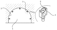
즉, 도 1은 종래의 터널에 부착된 측량 타겟을 나타낸 도면으로서, 도 1에 도시된 바와 같이 터널(1)의 내부 벽면(3)에 다수개의 측량 타겟(2)이 일정 간격을 두고 고정적으로 부착되어 있는데, 이러한 측량 타겟(2)은 말굽(∪)형상의 타겟 지지대(4) 내측에 반사판(6)을 일정 각도를 갖도록 고정적으로 결합되어 있는 형상으로 이루어져 있다.That is, FIG. 1 shows a survey target attached to a conventional tunnel. As shown in FIG. 1, a plurality of
작업자는 레이저 광선발사장치(미도시)를 조작하여 측량하고자 하는 터널 부위에 부착되어 있는 측량 타겟(2)의 반사판(6)을 향하여 레이저 광선을 발사하여 반사되는 광선을 취함으로써, 해당 측량 타겟(2)이 설치된 터널 부위의 내공 변위량을 파악할 수 있게 되는 것이다.The operator operates the laser beam launching device (not shown) to emit a laser beam toward the
그러나, 이러한 종래의 측량 타겟(2)의 경우에는 반사판(6)이 타겟 지지대(4)에 고정적으로 결합되어 있기 때문에, 터널 내부의 계속적인 발파를 위해 폭발물이나 대형 굴착기 등으로 작업을 지속하는 과정에서 굴착부로부터 예기치 않게 고속으로 날아오는 바위나 돌 등의 파편을 맞게 되면, 고정적으로 결합된 반사판(6)이 충격을 이기지 못하게 되어 타겟 지지대(4)를 터널 벽면에 앵커링하여 고정시켜 놓은 앵커 볼트가 크게 틀어져서 변위량 측정 타겟으로서 사용이 불가능하게 되거나, 심하게는 앵커 볼트가 벽면으로부터 완전히 탈락되어 측량 타겟이 떨어져 버린다는 문제점이 발생하게 된다.However, in the case of such a
따라서 종래에는 위의 문제를 해결하기 위하여 터널 시공시 내공변위 및 천단 침하의 측정을 위해 부착되는 측량 타겟을 외부로부터 발파 충격을 받으면 폴딩되어 충격 흡수가 가능한 폴더형 측량 타겟(등록실용신안 20-0446441)이 개발되었다.Therefore, in order to solve the above problem, in order to solve the above problem, a surveying target attached for measurement of the internal displacement and the subsidence at the time of construction of a tunnel is folded and absorbed shock from the outside, ) Was developed.
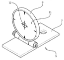
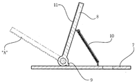
상기 종래의 폴더형 측량 타겟(5)은, 도 2 및 도 3에서 보는 바와 같이 지지패널(7)의 상부에 반사판(8)을 전방측으로만 회전식으로 접혀지게 반사판의 하단부를 힌지식으로 설치하며, 반사판의 후방하측에는 반사판이 뒤로 젖혀지지 않게 하는 스토퍼(9)가 돌출되게 형성되어 있다.2 and 3, the conventional folding
그리고, 반사판(8)의 후면과 후방측 지지패널(7)의 사이에는 반사판이 후방측으로 당겨지게 하는 스프링(10)이 탄력적으로 설치되며, 반사판(8)의 전면에는 타겟이 되는 측량용 반사시트지(11)가 부착되어 있다.A
이와 같은 종래고안은 폭발물이나 대형 굴착기 등으로 작업을 지속하는 과정에서 굴착부로부터 예기치 않게 고속으로 날아오는 바위나 돌 등의 파편이 반사판(8)의 후면에 부딪치게 되면, 그 충격력에 의해 반사판이 전방으로 도 3의 "A"와 같이 접혔다가 스프링(10)의 탄력에 의해 원위치로 복귀하게 되는 것이다.Such a conventional apparatus has a problem that when a piece of rock or stone that comes flying at an unexpectedly high speed from the excavation section strikes the rear surface of the
그리고, 위의 종래고안도 레이저 광선발사장치(미도시)를 조작하여 측량하고자 하는 터널 부위에 부착되어 있는 측량 타겟(2)의 반사판(6)을 향하여 레이저 광선을 발사하여 반사되는 광선을 취함으로써, 해당 측량 타겟(2)이 설치된 터널 부위의 내공 변위량을 파악할 수 있게 된다.Then, by operating a laser beam launching device (not shown) above, the laser beam is emitted toward the
그러나, 이러한 종래고안은 먼저 측량하였다가 일정시간이 경과한 뒤에 다시 측량할 때, 측량용 반사시트지(11)의 중앙에 표시된 타겟좌표점(12)의 상하 또는 좌우로의 변위는 파악할 수 있으나, 폴더형 측량타겟(5)이 미세하게 경사지는 것은 파악하지 못하였다.However, in this prior art design, the displacement of the
위와 같이 종래의 폴더형 측량타겟(5)이 미세하게 경사지는 것은 파악하지 못하지 못한 다는 것은, 그 폴더형 측량타겟(5)을 설치한 터널의 천정이나 내부 벽면이 변형이 생기고 있는데도 불구하고 그 미세한 변위량을 파악하지 못하여 안전사고를 예방하지 못하게 되는 문제가 있는 것이다.The fact that the conventional folding
본 고안은 상기의 문제점을 해결하기 위한 것으로서, 타겟본체를 신축성이 우수한 연질합성수지나 고무재로서 형성하되, 표적지가 부착되는 수직부의 양측면과 상면에는 수준기삽입홈을 형성한 뒤에, 터널에 터널 변위측정용 타겟을 설치하는 위치에 따라 수준기를 수준기삽입홈에 설치함으로서, 발파 등의 작업과정에서 날아오는 돌멩이 등의 부딪치는 경우에 수직부가 휘어졌다가 원위치로 탄력적으로 복귀함은 물론이고, 터널 변위측정용 타겟을 설치한 터널 내부면의 미세한 기울여짐까지 사전에 확인하여 붕괴사고 등의 안전사고를 예방할 수 있도록 하는 것을 기술적 과제로 한다.It is an object of the present invention to solve the above-mentioned problems, and it is an object of the present invention to provide a method of manufacturing a tunnel structure, in which a target body is formed as soft synthetic resin or rubber material excellent in stretchability, a leveling groove is formed on both sides and an upper surface of a vertical portion to which a target is adhered, When the level is set in the level insertion groove according to the installation position of the target, the vertical portion is flexed and resiliently returned to the original position in the case of colliding stones coming from the work process such as blasting, It is a technical task to prevent a safety accident such as a collapse accident by confirming a minute inclination of the inner surface of the tunnel in which the target is installed.
상기의 목적을 달성하기 위한 본 고안은, 신축성이 우수한 연질합성수지재나 또는 고무재로서 "ㄴ"자 형태로 수직부와 수평부가 일체로 형성되어 타겟본체가 형성되고, 수평부에는 앙카볼트 설치용 볼트구멍이 형성되며; 수직부의 중앙에 표적지가 부착되고, 표적지가 부착되는 수직부의 전면측에 수평방향과 수직방향에 수준기삽입홈이 각각 형성되며, 터널 변위측정용 타겟을 설치하는 터널의 내면 위치에 따라 수평 및 수직방향에 형성된 수준기삽입홈 중의 어느 하나의 수준기삽입홈에 1개의 수준기를 설치하고; 상기 표적지는 중앙에 야광부재로 타겟 중앙좌표점이 형성되고, 타겟 중앙좌표점을 중심으로 수직선과 수평선, 그리고 동심원이 표시되며, 상기 수직부는 중앙부가 상하방향으로 두껍고 양측이 얇게 형성되는 구성이 포함되는 것을 특징으로 한다.In order to achieve the above object, the present invention relates to a flexible synthetic resin material or rubber material having excellent elasticity and having a vertical part and a horizontal part integrally formed in a " / RTI > A leveling insertion groove is formed in a horizontal direction and a vertical direction on a front surface side of a vertical portion to which a target is attached, and a leveling insertion groove is formed in the horizontal and vertical directions according to the inner surface position of the tunnel for setting the tunneling displacement measurement target One leveling means is provided in one of the leveling insertion grooves of the leveling insertion grooves formed in the leveling means; Wherein the target has a target center coordinate point formed by a luminous member in the center, a vertical line, a horizontal line, and a concentric circle are displayed around the target center coordinate point, and the center portion is thick in the vertical direction and thin on both sides .
이상에서 살펴본 바와 같은 본 고안의 터널 변위측정용 타겟은, 타겟본체를 신축성이 우수한 연질합성수지나 고무재로서 형성하되, 표적지가 부착되는 수직부의 양측면과 상면에는 수준기삽입홈을 형성한 뒤에, 터널에 터널 변위측정용 타겟을 설치하는 위치에 따라 수준기를 수준기삽입홈에 설치함으로서, 발파 등의 작업과정에서 날아오는 돌멩이 등의 부딪치는 경우에 수직부가 휘어졌다가 원위치로 탄력적으로 복귀함은 물론이고, 터널 변위측정용 타겟을 설치한 터널 내부면의 미세한 기울여짐까지 사전에 확인하여 붕괴사고 등의 안전사고를 예방할 수 있는 효과가 있는 것이다.As described above, the target for the tunnel displacement measurement of the present invention is formed by forming the target body as soft synthetic resin or rubber material having excellent stretchability, forming leveling grooves on both sides and upper surfaces of the vertical portion to which the target is attached, When the level is inserted into the level insertion groove according to the position where the tunnel displacement measurement target is installed, the vertical portion is flexed and resiliently returned to the original position in the case of colliding stones coming from the work process such as blasting, It is possible to prevent a safety accident such as a collapse accident by confirming a minute inclination of the inner surface of the tunnel in which the tunnel displacement measurement target is installed.
또한, 수직부의 전면에는 끼움돌기가 구비된 표적지부착홈을 형성한 뒤에 표적지에는 상기 끼움돌기에 끼워지는 끼움구멍을 형성하여 표적지를 수직부의 전면에 정확하고 간편하게 부착할 수 있는 효과가 있는 것이다.In addition, after forming a groove for attaching a target with a fitting protrusion on the front surface of the vertical portion, an insertion hole that is fitted in the fitting protrusion is formed on the target, so that the target can be accurately and easily attached to the front surface of the vertical portion.
도 1은 터널에 타겟을 설치한 상태를 나타내는 도면.
도 2는 종래고안을 나타내는 사시도.
도 3은 도 2에 도시된 종래고안의 측단면도.
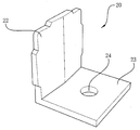
도 4는 본 고안의 일실시예를 나타내는 정면사시도.
도 5는 본 고안의 이실시예를 나타내는 정면사시도.
도 6은 도 5에 도시된 이실시예의 측단면도.
도 7은 본 고안에 따른 일,이실시예를 나타내는 배면사시도.
도 8은 본 고안에 따른 터널 변위측정용 타겟의 사용상태를 나타내는 사시도.1 is a view showing a state in which a target is installed in a tunnel.
2 is a perspective view showing a conventional design.
3 is a side cross-sectional view of the prior art shown in Fig.
4 is a front perspective view showing an embodiment of the present invention;
FIG. 5 is a front perspective view showing an example of a change in the present invention. FIG.
FIG. 6 is a side cross-sectional view of the embodiment shown in FIG. 5; FIG.
FIG. 7 is a rear perspective view showing an example of a work according to the present invention; FIG.
8 is a perspective view showing a use state of a tunnel displacement measurement target according to the present invention;
이하, 본 고안에 따른 터널 변위측정용 타겟에 대하여 첨부된 도면 도 4 내지 도 8을 참고하여 설명하면 다음과 같다.Hereinafter, the target for tunnel displacement measurement according to the present invention will be described with reference to FIGS. 4 to 8 attached hereto.
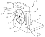
도 4 및 도 7에 도시된 본 고안의 일실시예에 따른 터널 변위측정용 타겟(20)은, 신축성이 우수한 연질합성수지재나 또는 고무재로서 "ㄴ"자 형태로 타겟본체(21)가 형성되고, 이 타겟본체(21)의 수평부(23)에는 터널의 천정면이나 내측면부와 같은 내부면에 앙카볼트로 고정 설치하기 위한 볼트구멍(24)이 형성된다.The
그리고, 수직부(22)는 중앙에 표적지(25)가 부착되고, 표적지(25)가 부착되는 수직부(22)의 전면측에 수평방향과 수직방향에 수준기삽입홈(30)이 각각 형성되는데, 도 4에서는 표적지(25)의 상부에 수평방향으로 수준기삽입홈(30)을 형성하고 표적지(25)의 양측에 수직방향으로 2개의 수준기삽입홈(30)을 형성하였으나, 수평방향과 수직방향에 각각 1개씩만 형성해도 무방하다.The
그리고, 이들 수준기삽입홈(30)에는 수준기(31)를 설치하되, 터널 변위측정용 타겟(20)을 설치하는 터널의 내면 위치에 따라 3개의 수준기삽입홈(30) 중의 어느 하나의 수준기삽입홈(30)에 1개의 수준기(31)를 설치하는 것이 제품단가를 절감시킬 수 있어 바람직하다.The
상기 표적지(25)는 중앙에 야광부재로 타겟 중앙좌표점(29)이 형성되고, 타겟 중앙좌표점(29)을 중심으로 수직선(26)과 수평선(27), 그리고 동심원(28)이 표시되며, 상기 수직부(22)는 평면모양이 넓적한 오각형이 되도록 중앙부의 두께가 두껍고 양측을 얇게 형성하여 휘어졌다가 원위치로의 복귀력이 우수하도록 형성하였음을 밝혀둔다.A target
도 5 및 도 6에 도시된 이실시예는 일실시예에 표적지(25)를 정확하고 간편하게 정확하게 부착하기 위한 부착부의 구조만 추가 구성한 것이므로, 일실시예와 동일한 부분에 대한 구성은 생략하고 추가되는 부착부의 구성에 대해서만 추가로 설명하기로 한다.5 and 6, since only the structure of the attaching portion for correctly and easily and accurately attaching the
즉, 표적지(25)를 부착하는 부착부는 수직부(22)의 전면에 표적지(25)가 삽입될 만큼의 깊이로 표적지부착홈(32)이 형성되고, 표적지부착홈(32)의 수직방향이나 또는 수직방향에 한 쌍의 끼움돌기(33)를 돌출 형성하며, 상기 표적지(25)에는 상기 끼움돌기(33)가 끼워지는 끼움구멍(25a)이 형성되어 표적지(25)를 정확한 위치에 간편하게 부착할 수 있는 것이다. That is, the attachment portion for attaching the
상기와 같이 구성되어 있는 본 고안의 작용관계를 도 4 내지 도 8을 참고하여 설명하면 다음과 같다.The operation of the present invention constructed as described above will now be described with reference to FIGS. 4 to 8. FIG.
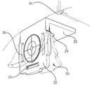
본 고안에 의한 터널 변위측정용 타겟(20)은 도 8에서 보는 바와 같이 터널의 터널내벽면(34)에 수평부(23)가 앙카볼트에 의해 고정 설치되는데, 이 터널 변위측정용 타겟(20)은 터널의 좌우측 내면과 천정면에 고정설??된다.As shown in FIG. 8, the tunnel
이때, 상기 터널 변위측정용 타겟(20)을 천정면에 설치할 때는 수직부(22)에 수평방향으로 형성된 수준기(31)를 삽입 설치하고, 터널 변위측정용 타겟(20)을 터널의 내측면에 설치할 때는 수직부(22)에 수직방향으로 설치된 수준기삽입홈(30)에 수준기(31)를 설치하는데, 이렇게 터널 변위측정용 타겟(20)을 천정면에 설치했을때나 내측벽면에 설치했을 때, 수준기(31)는 모두 수평한 상태로 배치되게 된다.At this time, when the tunnel
이렇게 터널 변위측정용 타겟(20)을 터널의 천정면이나 내측벽면에 설치할 때, 수준기(31)의 기포부분이 수준기(31)의 정 가운데에 위치하도록 터널 변위측정용 타겟(20)을 설치하는데, 발파된 터널 내벽면이 울퉁불퉁하여 수준기(31)의 기포부분이 정 가운데로 오도록 수평부(23)에 납작한 나무조각과 같은 끼움재를 끼워 넣으면서 위에서 언급한 수준기(31)의 기포부분이 수준기(31)의 가운데에 위치하도록 한다.When the tunnel
이와 같이 터널의 천정면과 내측벽면에 수개의 터널 변위측정용 타겟(20)을 설치한 뒤에는, 종래의 레이저 광선발사장치(미도시)를 이용하여 측량하는 방식과 동일하게 각각의 터널 변위측정용 타겟(20)을 촬영하는데, 이는 광선발사장치에서 발사된 레이저광선이 터널 변위측정용 타겟(20)의 표적지(25)에 레이저 광선을 조사하고 그렇게 조사된 광선이 반사되어 오는 값을 저장하여 측량을 하는데, 이때 수준기(31)의 기포부분의 위치까지 측량 저장하게 된다.After a plurality of
이 상태에서 터널 내부를 더 깊이 발파하거나 굴착기등의 장비를 이용하여 터널 굴착작업을 하는 과정에서 돌멩이가 비산하면서 터널 변위측정용 타겟(20)의 후면에 부딪치게 되면, 이 터널 변위측정용 타겟(20)는 타겟본체(21) 자체가 고무재나 연질합성수지재와 같이 신축성이 우수하며 부드러운 소재로 제작 형성되어서, 상기 돌멩이가 부딪치는 순간에 그 충격에 의해 수직부(22)가 전방측으로 휘었다가 원위치로 복귀하게 된다.In this state, when the inside of the tunnel is more deeply bumped or the tunnel is excavated using an excavator or the like, when the stone is scattered and strikes against the rear surface of the tunnel
이때, 상기 수직부(22)는 도 7에서 보는 바와 같이 평면에서 보았을 때 납작한 오각형 모양으로 형성되되, 가운데부분이 상하방향으로 두껍고 양측이 얇은 형태로 형성되어서 수직부(22)가 휘어졌다가 원위치로 복귀되는 것이 빠르게 이루어진다.As shown in FIG. 7, the
따라서, 본 고안에 의한 터널 변위측정용 타겟(20)에 돌멩이가 날아와 부딪치는 경우에도 터널 변위측정용 타겟(20)이 파손되지 않고 터널의 내벽면에 고정 상태를 유지하게 되는 것이다.Therefore, even when the
이와 같이 다수의 터널 변위측정용 타겟(20)이 터널의 내벽면에 설치된 상태에서 각종의 작업을 진행하는 과정에서 소정의 깊이만큼 터널내부에 대한 굴착작업을 한 뒤에, 또 다시 터널 내부를 더 깊게 발파를 포함한 굴착을 하거나, 또 다른 터널내부에 대한 작업을 다시 실행하고자 하는 경우에는 먼저, 측량하였던 터널 변위측정용 타겟(20)에 대하여 재차 광선발사장치로 촬영을 실시한다.In this way, in the course of various operations in the state where the
이렇게 다시 터널 변위측정용 타겟(20)에 대한 측량작업을 했을 때, 표적지(25)의 타겟 중앙좌표점(29)이 이동하게 되었다면 그 변위량에 따라 터널내부가 붕괴할 수 있음을 파악할 수 있게 되는 것이며, 상기 타겟 중앙좌표점(29)의 변위는 없더라도 수준기(31)의 기포부분에 대한 위치이동이 생긴 경우라면 터널 변위측정용 타겟(20)이 경사지고 있음을 나타내는 것이 된다.When the target
이러한 수준기(31)의 기포부분이 위치가 이동하는 것은 터널 변위측정용 타겟(20)이 설치된 터널 내벽면이 육안으로는 확인이 불가능할 만큼 미세한 변위도 측정 확인하게 되어 추후 붕괴사고에 대비할 수 있게 되는 것이다.The position of the bubble portion of the
그리고, 도 5, 6에 도시된 이실시예는 일실시예와 전체적으로 유사한데다가 표적지(25)를 정확한 위치에 간편하고 신속하게 부착하기 위한 구성이 포함된 것이다.5 and 6 is generally similar to the embodiment and includes a configuration for easily and quickly attaching the
즉, 수직부(22)의 전면에 표적지(25)가 삽입될 표적지부착홈(32)이 형성되고, 그 표적지부착홈(32)에는 상하방향이나, 또는 좌우방향으로 한 쌍의 끼움돌기(33)가 돌출 형성되어 있는 상태에서 표적지(25)에는 상기 끼움돌기(33)이 끼워지는 끼움구멍(25a)이 형성되어서 끼움구멍(25a)을 끼움돌기(33)에 끼워 넣으면서 표적지(25)를 표적지부착홈(32)에 삽입시키면 표적지(25)를 수직부(22)의 전면에 정확하고 간편하면 신속하게 정위치에 부착할 수 있는 것이다.The front surface of the
따라서, 끼움구멍(25a)을 끼움돌기(33)에 끼워 넣으면서 표적지(25)를 표적지부착홈(32)에 삽입 부착함에 따라 표적지(25)가 삐뚤어지지 않고 항상 수직선(26)과 수평선(27)이 항상 정확 수직방향과 수평방향으로 설치되게 는 것이며, 추후에 광선발사장치를 이용하여 터널 변위측정용 타겟(20)을 측량 촬영하는 경우에 정확한 측정이 이루어질 수 있게 되는 것이다.Therefore, as the
상기 표적지(25)의 중앙에 표시되는 타겟 중앙좌표점(29)은 야광으로 표시하여 광선발사장치나 육안으로 더욱더 잘 보이게 하였음을 밝혀둔다.It is noted that the target
20 : 터널 변위측정용 타겟 21 : 타겟본체 22 : 수직부
23 : 수평부 24 : 볼트구멍 25 : 표적지
26 : 수직선 27 : 수평선 28 : 동심원
29 : 타겟 중앙좌표점 30 : 수준기삽입홈 31 : 수준기
32 : 표적지부착홈 33 : 끼움돌기 34 : 터널내벽면20: Tunnel displacement measurement target 21: Target body 22: Vertical section
23: horizontal portion 24: bolt hole 25: target
26: vertical line 27: horizontal line 28: concentric circle
29: Target center point 30: Insert level groove 31: Level
32: target attachment groove 33: fitting projection 34: wall in tunnel
Claims (2)
수직부(22)의 중앙에 표적지(25)가 부착되고, 표적지(25)가 부착되는 수직부(22)의 전면측에 수평방향과 수직방향에 수준기삽입홈(30)이 각각 형성되며, 터널 변위측정용 타겟(20)을 설치하는 터널의 내면 위치에 따라 수평 및 수직방향에 형성된 수준기삽입홈(30) 중의 어느 하나의 수준기삽입홈(30)에 1개의 수준기(31)를 설치하고;
상기 표적지(25)는 중앙에 야광부재로 타겟 중앙좌표점(29)이 형성되고, 타겟 중앙좌표점(29)을 중심으로 수직선(26)과 수평선(27), 그리고 동심원(28)이 표시되며, 상기 수직부(22)는 중앙부가 상하방향으로 두껍고 양측이 얇게 형성되는 구성이 포함되는 것을 특징으로 하는 터널 변위측정용 타겟.The vertical portion 22 and the horizontal portion 23 are integrally formed as a flexible synthetic resin material or a rubber material having excellent elasticity to form a target body 21. The horizontal portion 23 is provided with an anchor bolt- A bolt hole 24 is formed;
A leveling instrument insertion groove 30 is formed in the horizontal direction and the vertical direction on the front surface side of the vertical portion 22 to which the target 25 is attached and the tunnel 25 is attached to the center of the vertical portion 22, One leveling instrument (31) is provided in any leveling instrument insertion groove (30) of the leveling instrument insertion groove (30) formed in the horizontal and vertical directions in accordance with the inner surface position of the tunnel in which the displacement measurement target (20) is installed;
A target center coordinate point 29 is formed by a luminous member in the center of the target 25 and a vertical line 26, a horizontal line 27 and a concentric circle 28 are displayed around the target center coordinate point 29 , And the vertical part (22) has a structure in which the central part is thick in the vertical direction and thin on both sides.
Priority Applications (1)
| Application Number | Priority Date | Filing Date | Title |
|---|---|---|---|
| KR2020170003233U KR20190000006U (en) | 2017-06-22 | 2017-06-22 | A target for measure the displacement in tunnel |
Applications Claiming Priority (1)
| Application Number | Priority Date | Filing Date | Title |
|---|---|---|---|
| KR2020170003233U KR20190000006U (en) | 2017-06-22 | 2017-06-22 | A target for measure the displacement in tunnel |
Publications (1)
| Publication Number | Publication Date |
|---|---|
| KR20190000006U true KR20190000006U (en) | 2019-01-02 |
Family
ID=65012164
Family Applications (1)
| Application Number | Title | Priority Date | Filing Date |
|---|---|---|---|
| KR2020170003233U Ceased KR20190000006U (en) | 2017-06-22 | 2017-06-22 | A target for measure the displacement in tunnel |
Country Status (1)
| Country | Link |
|---|---|
| KR (1) | KR20190000006U (en) |
Cited By (2)
| Publication number | Priority date | Publication date | Assignee | Title |
|---|---|---|---|---|
| KR102289894B1 (en) * | 2020-10-30 | 2021-08-13 | 주식회사 경진그린텍 | tarket with prevent damage caused by external shock |
| CN118623847A (en) * | 2024-08-08 | 2024-09-10 | 兰州天瑞测绘工程有限公司 | Remote sensing mapping marking device and use method |
Citations (1)
| Publication number | Priority date | Publication date | Assignee | Title |
|---|---|---|---|---|
| KR20040046441A (en) | 2002-11-27 | 2004-06-05 | (주)코스타 월드 | Cosmetic compact and table mirror with an internal lighting device |
-
2017
- 2017-06-22 KR KR2020170003233U patent/KR20190000006U/en not_active Ceased
Patent Citations (1)
| Publication number | Priority date | Publication date | Assignee | Title |
|---|---|---|---|---|
| KR20040046441A (en) | 2002-11-27 | 2004-06-05 | (주)코스타 월드 | Cosmetic compact and table mirror with an internal lighting device |
Cited By (2)
| Publication number | Priority date | Publication date | Assignee | Title |
|---|---|---|---|---|
| KR102289894B1 (en) * | 2020-10-30 | 2021-08-13 | 주식회사 경진그린텍 | tarket with prevent damage caused by external shock |
| CN118623847A (en) * | 2024-08-08 | 2024-09-10 | 兰州天瑞测绘工程有限公司 | Remote sensing mapping marking device and use method |
Similar Documents
| Publication | Publication Date | Title |
|---|---|---|
| US7316073B2 (en) | Studfinder and laser line layout tool | |
| EP1367365B2 (en) | Laser level with object detector | |
| AU2009328380B2 (en) | Laser receiver for detecting a relative position | |
| KR102171730B1 (en) | Geodetic surveying device to minimizie error | |
| KR102307335B1 (en) | Geodetic surveying system for improving survey accuracy by reducing error in level survey data | |
| US20160377431A1 (en) | Survey device | |
| US5631732A (en) | Surveyor device | |
| EP2825842A1 (en) | Laser receiver | |
| KR20190000006U (en) | A target for measure the displacement in tunnel | |
| JP5792783B2 (en) | Rock drilling rig and rock drilling unit positioning method | |
| EP3213142A1 (en) | Laser light reflective target | |
| JP2627871B2 (en) | 3D survey target | |
| EP3309510A1 (en) | Height-adjustable laser level apparatus | |
| KR101494857B1 (en) | Bench mark surveying system | |
| CN101278171B (en) | Double-sided reflector and double-sided sighting device | |
| US8848180B1 (en) | Reference systems for indicating slope and alignment and related devices, systems, and methods | |
| KR200477287Y1 (en) | a target with radiation | |
| US11378385B2 (en) | Dual laser distance measurer with midpoint locating feature | |
| KR101157894B1 (en) | Level surveying using a assembly level point device | |
| CN209263941U (en) | Angle gauge with angle line casting function | |
| JP2003294445A (en) | Ink detector with built-in rangefinder | |
| KR100572989B1 (en) | Drilling Pattern Marking Method and Device | |
| CN1965211B (en) | device for positioning markers | |
| KR101234345B1 (en) | Apparatus for measuring level point using equal distance survey | |
| KR102456538B1 (en) | Sliding inner target |
Legal Events
| Date | Code | Title | Description |
|---|---|---|---|
| A201 | Request for examination | ||
| UA0108 | Application for utility model registration |
Comment text: Application for Utility Model Registration Patent event code: UA01011R08D Patent event date: 20170622 |
|
| UA0201 | Request for examination | ||
| E902 | Notification of reason for refusal | ||
| UE0902 | Notice of grounds for rejection |
Comment text: Notification of reason for refusal Patent event code: UE09021S01D Patent event date: 20180531 |
|
| E601 | Decision to refuse application | ||
| UE0601 | Decision on rejection of utility model registration |
Comment text: Decision to Refuse Application Patent event code: UE06011S01D Patent event date: 20181219 |
|
| UG1501 | Laying open of application |