KR20200003473A - Ozone and sludge disposal system of plasma generator - Google Patents
Ozone and sludge disposal system of plasma generator Download PDFInfo
- Publication number
- KR20200003473A KR20200003473A KR1020180076301A KR20180076301A KR20200003473A KR 20200003473 A KR20200003473 A KR 20200003473A KR 1020180076301 A KR1020180076301 A KR 1020180076301A KR 20180076301 A KR20180076301 A KR 20180076301A KR 20200003473 A KR20200003473 A KR 20200003473A
- Authority
- KR
- South Korea
- Prior art keywords
- ozone
- water
- sludge
- cross
- ejector
- Prior art date
- Legal status (The legal status is an assumption and is not a legal conclusion. Google has not performed a legal analysis and makes no representation as to the accuracy of the status listed.)
- Granted
Links
Images


Classifications
-
- B—PERFORMING OPERATIONS; TRANSPORTING
- B08—CLEANING
- B08B—CLEANING IN GENERAL; PREVENTION OF FOULING IN GENERAL
- B08B7/00—Cleaning by methods not provided for in a single other subclass or a single group in this subclass
- B08B7/04—Cleaning by methods not provided for in a single other subclass or a single group in this subclass by a combination of operations
-
- B—PERFORMING OPERATIONS; TRANSPORTING
- B05—SPRAYING OR ATOMISING IN GENERAL; APPLYING FLUENT MATERIALS TO SURFACES, IN GENERAL
- B05B—SPRAYING APPARATUS; ATOMISING APPARATUS; NOZZLES
- B05B1/00—Nozzles, spray heads or other outlets, with or without auxiliary devices such as valves, heating means
- B05B1/02—Nozzles, spray heads or other outlets, with or without auxiliary devices such as valves, heating means designed to produce a jet, spray, or other discharge of particular shape or nature, e.g. in single drops, or having an outlet of particular shape
- B05B1/06—Nozzles, spray heads or other outlets, with or without auxiliary devices such as valves, heating means designed to produce a jet, spray, or other discharge of particular shape or nature, e.g. in single drops, or having an outlet of particular shape in annular, tubular or hollow conical form
-
- B—PERFORMING OPERATIONS; TRANSPORTING
- B08—CLEANING
- B08B—CLEANING IN GENERAL; PREVENTION OF FOULING IN GENERAL
- B08B3/00—Cleaning by methods involving the use or presence of liquid or steam
- B08B3/02—Cleaning by the force of jets or sprays
-
- B—PERFORMING OPERATIONS; TRANSPORTING
- B08—CLEANING
- B08B—CLEANING IN GENERAL; PREVENTION OF FOULING IN GENERAL
- B08B3/00—Cleaning by methods involving the use or presence of liquid or steam
- B08B3/04—Cleaning involving contact with liquid
- B08B3/10—Cleaning involving contact with liquid with additional treatment of the liquid or of the object being cleaned, e.g. by heat, by electricity or by vibration
- B08B3/14—Removing waste, e.g. labels, from cleaning liquid
-
- B—PERFORMING OPERATIONS; TRANSPORTING
- B08—CLEANING
- B08B—CLEANING IN GENERAL; PREVENTION OF FOULING IN GENERAL
- B08B9/00—Cleaning hollow articles by methods or apparatus specially adapted thereto
- B08B9/02—Cleaning pipes or tubes or systems of pipes or tubes
- B08B9/027—Cleaning the internal surfaces; Removal of blockages
Landscapes
- Engineering & Computer Science (AREA)
- Mechanical Engineering (AREA)
- Treatment Of Water By Oxidation Or Reduction (AREA)
Abstract
Description
본 발명은 플라즈마 발생기 내부에서 플라즈마 발생시 부수적으로 발생하는 오존 및 슬러지를 처리하는 시스템에 관한 것으로써, 보다 상세하게는 플라즈마 발생기 내부에서 발생하여 외부로 배출되는 오존 및 슬러지가 각각 이젝터 내부에서 용수에 용해되도록 하고, 오존 및 슬러지 용해 후 폭기조에 저장되는 용수를 순환시켜 오존 및 슬러지를 지속적으로 용해하도록 하는 시스템에 관한 것이다. The present invention relates to a system for treating ozone and sludge which is incidentally generated during plasma generation in a plasma generator, and more specifically, ozone and sludge generated in the plasma generator and discharged to the outside are dissolved in water in the ejector, respectively. The present invention relates to a system for continuously dissolving ozone and sludge by circulating water stored in an aeration tank after dissolving ozone and sludge.
일반적으로, 플라즈마는 초고온에서 음전하를 가진 전자와 양전하를 띤 이온으로 분리된 기체 상태로써 ‘제4의 물질상태’라 불리고 있으며, 발생 방식에 따라 각기 다른 물리화학적 특징을 가지게 되므로 반도체, 조명, 디스플레이, 의료장비, 환경 개선 사업 및 신에너지 개발 등 다양한 분야에 복합적으로 이용 가능한 장점이 있다.In general, plasma is a gaseous state that is divided into electrons with positive charges and positively charged ions at very high temperatures, and is called a 'fourth material state', and has different physical and chemical characteristics depending on the generation method. , Medical equipment, environmental improvement projects, and new energy developments can be used in various fields.
한편, 플라즈마의 발생시 발생하게 되는 오존은 강한 산화력을 가지는 특성으로 인해 인체의 호흡 기관에 악영향을 끼치고 금속을 부식시키는 문제가 있으므로 플라즈마 발생기의 외부로 신속히 배출하여 처리할 필요성이 있다.On the other hand, ozone generated during the generation of plasma has a problem of adversely affecting the respiratory organs of the human body and corrosion of the metal due to the characteristics of having a strong oxidizing power, it is necessary to quickly discharge to the outside of the plasma generator for treatment.
종래의 오존 처리에 관한 발명으로는 대한민국 등록특허공보 제10-1529048호의 “오존처리수 내의 잔류용존오존 제거방법 및 그 장치” 및 대한민국 등록특허공보 제10-1864137호의 “오존 용해 가속기를 구비한 플라즈마 수처리 시스템”, 대한민국 공개특허공보 제10-2018-0066884호의 “오존 방출 없는 플라즈마 공기청정기”가 제안되어 공개된 바 있다.Conventional inventions relating to ozone treatment include "Residual dissolved ozone removal method and apparatus therefor in ozone treated water" in Korean Patent Publication No. 10-1529048 and "Ozone Dissolution Accelerator" in Korean Patent Publication No. 10-1864137. Water treatment system ”, Republic of Korea Patent Publication No. 10-2018-0066884" Ozone-Free Plasma Air Purifier "has been proposed and published.
상기 대한민국 등록특허공보 제10-1529048호의 “오존처리수 내의 잔류용존오존 제거방법 및 그 장치”에는 오존 접촉조에서 오존처리하고 난 오존 처리수가 잔류용존오존 제거조의 내부로 유입되는 과정에서 용존오존을 1차 처리하고, 잔류용존오존 제거조에서 이를 폭기시켜 잔류용존오존을 2차 제거한 후 배오존 파괴설비에서 완전 제거함으로써, 환경기준치 이상의 용존오존이 대기 중에 방출되는 현상을 미연에 방지할 수 있는 방법 및 장치에 관한 발명이 제안되었고, 상기 대한민국 등록특허공보 제10-1864137호의 “오존 용해 가속기를 구비한 플라즈마 수처리 시스템”에는 플라즈마 오존발생기에서 생성 및 배출되는 오존을 이송하며 혼합기를 통해 오존버블수를 생성하고, 용해가속기의 오존주입부를 통해 마이크로 오존버블수를 생성하며, 마이크로 오존버블수를 상기 메인배관의 내부로 주입하는 과정에서 추가로 버블을 생성하고, 마이크로 오존버블수 및 원수를 용해가속기의 메인배관 내부에 수용된 라인믹서를 통과하여 이송하는 과정에서 추가로 버블을 생성하므로, 오존이 원수에 용해되는 과정이 수차례 진행되어 용해 효율이 증가되는 시스템에 관한 발명이 제안되었으며, 상기 대한민국 공개특허공보 제10-2018-0066884호의 “오존 방출 없는 플라즈마 공기청정기”에는 수조 탱크의 물이 다른 수조 탱크로 흐르는 과정에서 탱크 하단으로 공기 플라즈마가 주입되도록 구성됨으로써 물에 의하여 미세 먼지와 유기물 및 오존이 용해되어 완전히 정화된 공기를 배출할 수 있는 장치에 관한 발명이 제안되었다.The method and apparatus for removing residual dissolved ozone in ozone treated water in the Republic of Korea Patent Publication No. 10-1529048 discloses dissolved ozone in the process of introducing ozone treated water from the ozone contact tank into the residual dissolved ozone removing tank. The first treatment, aeration of the residual dissolved ozone removal tank to remove the residual dissolved ozone secondly, and then completely removed from the ozone demolition facility, thus preventing the release of dissolved ozone above the environmental standard to the air. And an invention related to an apparatus have been proposed, and the "plasma water treatment system having an ozone dissolution accelerator" of Korean Patent Publication No. 10-1864137 transmits ozone generated and discharged from a plasma ozone generator and supplies ozone bubble water through a mixer. Micro ozone bubble water through the ozone inlet of the melt accelerator, In the process of injecting chromium ozone bubble water into the main pipe, additional bubbles are generated, and the micro ozone bubble water and raw water are further bubbled through the line mixer accommodated in the main pipe of the melt accelerator. As a result, the invention relates to a system in which the process of dissolving ozone in raw water proceeds several times and the dissolution efficiency is increased, and the "Plasma Air Purifier without Ozone Emission" of the Republic of Korea Patent Publication No. 10-2018-0066884 Since the air plasma is injected into the bottom of the tank while the water in the tank flows to another tank tank, an invention has been proposed for an apparatus capable of discharging fine dust, organic matter, and ozone to completely purify air.
그러나 상기와 같은 종래 발명들은 플라즈마 발생시 발생하는 오존에 더하여 슬러지를 제거하는 방안은 제시하지 않고 있고, 오존을 용수 등에 수차례 용해하여 제거하는 등 오존을 제거하기 위한 설비가 복잡하고 오존의 제거에 오랜 시간이 걸리는 등의 문제가 있으므로, 플라즈마 발생시 발생하는 오존 및 슬러지를 동시에 처리할 수 있고, 설비가 간단하게 구성되어 오존 및 슬러지를 저비용으로 신속하게 처리할 수 있는 장치에 관한 발명이 요구되는 실정이다.However, the above-described conventional inventions do not suggest a method for removing sludge in addition to ozone generated during plasma generation, and a facility for removing ozone such as dissolving ozone by dissolving water several times is complicated and long time for ozone removal. Since there is a problem such as time consuming, there is a need for an invention regarding an apparatus capable of simultaneously treating ozone and sludge generated during plasma generation, and having a simple structure and rapidly treating ozone and sludge at low cost. .
본 발명에 의한 플라즈마 발생기의 오존 및 슬러지 처리 시스템은,The ozone and sludge treatment system of the plasma generator according to the present invention,
플라즈마 발생기 내부에서 플라즈마 발생 시에 발생하는 오존은 강한 산화력을 가지는 특성으로 인해 인체의 호흡 기관에 악영향을 끼치고 금속을 부식시키는 문제가 있으므로 외부로의 유출을 방지하며 처리되어야 할 필요성이 있고,Ozone generated when plasma is generated inside the plasma generator has a problem of adversely affecting the respiratory organs of the human body and corroding the metal due to the characteristics of having a strong oxidizing power, it is necessary to be treated to prevent leakage to the outside.
플라즈마 발생 시에 발생하여 내부에 쌓이는 슬러지도 처리되어야 할 필요성이 있으며,It is also necessary to process sludge generated in the plasma generation and accumulated inside.
오존 및 슬러지를 신속하게 처리하되, 처리 비용은 절감할 필요성이 있기 때문에, 이에 대한 해결책을 제시하는 것을 그 목적으로 한다.The purpose is to provide a solution to this problem because it is necessary to treat ozone and sludge quickly, but reduce the treatment cost.
본 발명에 의한 플라즈마 발생기의 오존 및 슬러지 처리 시스템은 상기와 같은 목적을 실현하고자,The ozone and sludge treatment system of the plasma generator according to the present invention to achieve the above object,
플라즈마를 발생시키는 플라즈마 발생기; 상기 플라즈마 발생기에 연결되어 플라즈마 발생시 발생하는 오존을 배출하는 오존 배출관; 내부에 중공이 형성되고, 상기 오존 배출관이 연결되는 오존 유입구가 형성되며, 상기 중공을 향하여 분사 노즐이 구비되며, 내부에 단면 축소부 및 단면 확장부가 순차로 형성되는 디퓨저가 구비되어 용수에 오존을 용해시키는 제1 이젝터; 상기 제1 이젝터의 분사 노즐에 용수를 공급하는 제1 용수 공급관; 상기 제1 이젝터의 디퓨저에 연결되어 오존이 용해된 용수를 배출하는 제1 용수 배출관; 상기 플라즈마 발생기에 연결되어 플라즈마 발생시 발생하는 슬러지를 배출하는 슬러지 배출관; 내부에 중공이 형성되고, 상기 슬러지 배출관이 연결되는 슬러지 유입구가 형성되며, 상기 중공을 향하여 분사 노즐이 구비되며, 내부에 단면 축소부 및 단면 확장부가 순차로 형성되는 디퓨저가 구비되어 용수에 슬러지를 용해시키는 제2 이젝터; 상기 제2 이젝터의 분사 노즐에 용수를 공급하는 제2 용수 공급관; 상기 제2 이젝터의 디퓨저에 연결되어 슬러지가 용해된 용수를 배출하는 제2 용수 배출관; 상기 제1 용수 배출관 및 상기 제2 용수 배출관으로부터 배출되는 용수를 저장하는 폭기조; 를 포함하여 구성되는 것을 특징으로 하는 플라즈마 발생기의 오존 및 슬러지 처리 시스템을 제시한다.A plasma generator for generating a plasma; An ozone discharge pipe connected to the plasma generator to discharge ozone generated when plasma is generated; A hollow is formed therein, an ozone inlet for connecting the ozone discharge pipe is formed, a spray nozzle is provided toward the hollow, and a diffuser in which the cross-sectional reduction part and the cross-sectional expansion part are sequentially formed is provided with ozone in the water. A first ejector to dissolve; A first water supply pipe for supplying water to the spray nozzle of the first ejector; A first water discharge pipe connected to the diffuser of the first ejector to discharge water in which ozone is dissolved; A sludge discharge pipe connected to the plasma generator to discharge sludge generated when plasma is generated; A hollow is formed therein, a sludge inlet is formed to which the sludge discharge pipe is connected, a spray nozzle is provided toward the hollow, and a diffuser in which a cross-sectional reduction part and a cross-sectional expansion part are sequentially formed is provided in the sludge in the water. A second ejector for dissolving; A second water supply pipe for supplying water to the spray nozzle of the second ejector; A second water discharge pipe connected to the diffuser of the second ejector to discharge water in which sludge is dissolved; An aeration tank for storing the water discharged from the first water discharge pipe and the second water discharge pipe; It provides an ozone and sludge treatment system of the plasma generator, characterized in that it comprises a.
본 발명에 의한 플라즈마 발생기의 오존 및 슬러지 처리 시스템은,The ozone and sludge treatment system of the plasma generator according to the present invention,
플라즈마 발생기 내부에서 발생한 오존 및 슬러지를 각각 이젝터 내부로 유입시킴으로써, 오존 및 슬러지가 고속으로 분사되는 용수에 의하여 용해되도록 하는 효과가 발생하였고,By injecting ozone and sludge generated inside the plasma generator into the ejector, respectively, the effect of dissolving ozone and sludge by water sprayed at high speed was generated.
이젝터, 펌프 및 복수 개의 관으로 오존 및 슬러지를 처리하기 위한 장치를 간단하게 구성하고, 오존 및 슬러지가 용해된 용수를 순환시켜 지속적으로 재활용되도록 함으로써, 오존 및 슬러지를 신속하게 처리 가능하되, 처리 비용은 절감할 수 있는 효과가 발생하였다.Easily configure the device for treating ozone and sludge with ejectors, pumps and plural pipes, and circulate the dissolved water in ozone and sludge to be continuously recycled, allowing for rapid treatment of ozone and sludge. Has the effect of saving.
도 1은 본 발명에 의한 플라즈마 발생기의 오존 및 슬러지 처리 시스템의 외부 사시도.
도 2는 본 발명에 의한 플라즈마 발생기의 오존 및 슬러지 처리 시스템 중 제1 이젝터의 내부 단면도.
도 3은 본 발명에 의한 플라즈마 발생기의 오존 및 슬러지 처리 시스템 중 제2 이젝터의 내부 단면도.
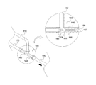
도 4(a) 및 도 4(b)는 본 발명에 의한 플라즈마 발생기의 오존 및 슬러지 처리 시스템의 경사부 각도에 따른 디퓨저 내부의 용수 흐름을 나타낸 예시도.
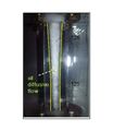
도 5(a) 및 도 5(b)는 본 발명에 의한 플라즈마 발생기의 오존 및 슬러지 처리 시스템의 디퓨저 내부 용수의 흐름을 촬영한 단면도.1 is an external perspective view of an ozone and sludge treatment system of a plasma generator according to the present invention.
Figure 2 is an internal cross-sectional view of the first ejector of the ozone and sludge treatment system of the plasma generator according to the present invention.
3 is an internal cross-sectional view of a second ejector of the ozone and sludge treatment system of the plasma generator according to the present invention;
Figure 4 (a) and Figure 4 (b) is an exemplary view showing the water flow inside the diffuser according to the inclination angle of the ozone and sludge treatment system of the plasma generator according to the present invention.
Figure 5 (a) and Figure 5 (b) is a cross-sectional view taken the flow of water inside the diffuser of the ozone and sludge treatment system of the plasma generator according to the present invention.
우선, 본 발명은 중소기업청에서 지원하는 2017년도 창업성장 기술개발사업(No.S2499496)의 연구수행으로 인한 결과물임을 밝히는 바이다.First of all, the present invention reveals that the result of the research of the 2017 Startup Growth Technology Development Project (No. S2499496) supported by the Small and Medium Business Administration.
본 발명은 플라즈마 발생기 내부에서 플라즈마 발생시 부수적으로 발생하는 오존 및 슬러지를 처리하는 시스템에 관한 것으로써,The present invention relates to a system for treating ozone and sludge generated incidentally during plasma generation in a plasma generator,
플라즈마를 발생시키는 플라즈마 발생기(100); 상기 플라즈마 발생기(100)에 연결되어 플라즈마 발생시 발생하는 오존을 배출하는 오존 배출관(110); 내부에 중공(121)이 형성되고, 상기 오존 배출관(110)이 연결되는 오존 유입구(122)가 형성되며, 상기 중공(121)을 향하여 분사 노즐(123)이 구비되며, 내부에 단면 축소부(125) 및 단면 확장부(126)가 순차로 형성되는 디퓨저(128)가 구비되어 용수에 오존을 용해시키는 제1 이젝터(120); 상기 제1 이젝터(120)의 분사 노즐(123)에 용수를 공급하는 제1 용수 공급관(130); 상기 제1 이젝터(120)의 디퓨저(128)에 연결되어 오존이 용해된 용수를 배출하는 제1 용수 배출관(140); 상기 플라즈마 발생기(100)에 연결되어 플라즈마 발생시 발생하는 슬러지를 배출하는 슬러지 배출관(150); 내부에 중공(161)이 형성되고, 상기 슬러지 배출관(150)이 연결되는 슬러지 유입구(162)가 형성되며, 상기 중공(161)을 향하여 분사 노즐(163)이 구비되며, 내부에 단면 축소부(165) 및 단면 확장부(166)가 순차로 형성되는 디퓨저(168)가 구비되어 용수에 슬러지를 용해시키는 제2 이젝터(160); 상기 제2 이젝터(160)의 분사 노즐(163)에 용수를 공급하는 제2 용수 공급관(170); 상기 제2 이젝터(160)의 디퓨저(168)에 연결되어 슬러지가 용해된 용수를 배출하는 제2 용수 배출관(180); 상기 제1 용수 배출관(140) 및 상기 제2 용수 배출관(180)으로부터 배출되는 용수를 저장하는 폭기조(190); 를 포함하여 구성되는 것을 특징으로 하는 플라즈마 발생기의 오존 및 슬러지 처리 시스템에 관한 것이다.A
이하에서는 첨부한 도면을 참조하여 본 발명의 실시예들을 상세히 설명하고자 한다.Hereinafter, with reference to the accompanying drawings will be described embodiments of the present invention;
우선, 도 1에 도시된 바와 같이 본 발명에 의한 플라즈마 발생기의 오존 및 슬러지 처리 시스템은 플라즈마를 발생시키는 플라즈마 발생기(100)를 포함하여 구성되는 것을 특징으로 한다.First, as shown in FIG. 1, the ozone and sludge treatment system of the plasma generator according to the present invention is characterized by including a
상기 플라즈마 발생기(100)는 초고온에서 음전하를 가진 전자와 양전하를 띤 이온으로 분리된 기체 상태이며, ‘제4의 물질상태’라 불리는 플라즈마를 발생시키는 장치로써, 장치의 성능 및 효율을 유지하고, 장치 내부의 부식을 방지하기 위하여 플라즈마의 발생 과정에서 부가적으로 발생하는 오존 및 슬러지의 제거가 요구된다.The
따라서, 도 1에 도시된 바와 같이 상기 플라즈마 발생기(100)에는 플라즈마 발생시 발생하는 오존을 배출하는 오존 배출관(110)의 일측 말단부가 상단에 연결되며, 상기 오존 배출관(110)의 타측 말단부는 하기 제1 이젝터(120)에 연결되어 제1 이젝터(120)의 내부로 오존이 이송되게 한다.Accordingly, as shown in FIG. 1, one end of an
도 2에 도시된 바와 같이 제1 이젝터(120)는 내부에 중공(121)이 형성되고, 상기 오존 배출관(110)의 타측 말단부가 연결되는 오존 유입구(122)가 형성되며, 상기 중공(121)을 향하여 분사 노즐(123)이 구비되며, 내부에 단면 축소부(125) 및 단면 확장부(126)가 순차로 형성되는 디퓨저(128)가 구비되어 용수에 오존을 용해 시키는 장치로써, 상기 분사 노즐(123)로부터 상기 디퓨저(128)를 향하여 고속으로 분사되는 용수에 의하여 중공(121) 내부에 체류하는 오존이 용수와 함께 디퓨저(128) 내부의 단면 축소부(125)로 진입하도록 하고, 단면 축소부(125) 내부에서 용수에 용해되도록 하며, 오존이 용해된 상태의 용수가 단면 확장부(126)를 통해 외부로 배출되도록 한다.As shown in FIG. 2, the
상기 분사 노즐(123)로부터 분사되는 고속의 용수에 의하여 상기 중공(121) 내부의 오존이 상기 디퓨저(128) 내부로 진입하게 되면 중공(121) 내부는 음압되므로 중공(121) 내부보다 높은 기압을 가지는 상기 오존 배출관(110)으로부터 오존을 빨아들이게 되고, 상기 단면 축소부(125)로 진입한 오존과 용수는 상기 디퓨저(128) 내부의 통로가 좁아짐에 따라 혼합되므로 오존이 용수에 용해되며, 단면 축소부(125)와 순차로 형성되는 상기 단면 확장부(126)는 오존이 용해된 상태의 용수가 용이하게 외부로 배출되도록 한다.When the ozone inside the hollow 121 enters into the
따라서, 도 1에 도시된 바와 같이 상기 분사 노즐(123)에는 제1 용수 공급관(130)의 일측 말단부가 연결되어 분사 노즐(123) 내부로 용수가 공급될 수 있도록 하고, 상기 디퓨저(128)에는 제1 용수 배출관(140)의 일측 말단부가 연결되어 오존이 용해된 상태의 용수가 배출될 수 있도록 한다.Accordingly, as shown in FIG. 1, one end of the first
이때, 상기 디퓨저(128)는 용수를 고속으로 분사하기 위하여 상기 분사 노즐(123)에 형성되는 분사공(124)의 직경을 기준으로 하는 상기 분사공(124)으로부터 상기 단면 축소부(125)까지의 거리가 동일한, 즉, 1:1 비율로 형성되는 것을 특징으로 하고, 상기 분사공(124)의 직경을 기준으로 하는 상기 단면 축소부(125)의 직경이 1:1.5 비율로 형성되는 것을 특징으로 하며, 상기 단면 축소부(125) 내부 통로의 길이를 기준으로 하는 상기 단면 확장부(126) 중 경사부(127)의 길이가 1:1 비율로 형성되는 것을 특징으로 하며, 상기 경사부(127)의 경사각도가 4 내지 6°로 형성되는 것을 특징으로 한다.At this time, the
위와 같은 구성은 제1 이젝터(120) 내부에서의 오존과 용수의 혼합을 위한 최적의 비율 및 경사각도 중 하나로써, 도 4(a)에 도시된 바와 같이 상기 경사부(127)의 경사각도가 4 내지 6°인 경우, 어떠한 속도 및 흐름을 가지는 용수가 상기 단면 확장부(126)로 유입되더라도 용수는 안정적으로 흘러나갈 수 있고, 내부 통로가 확장됨에 따라 유속은 감소하되 압력은 상승하여 상기 제1 이젝터(120)의 효율을 상승시키게 된다.The above configuration is one of the optimum ratio and the inclination angle for the mixing of ozone and water in the
이에 반하여, 도 4(b)에 도시된 바와 같이 상기 경사부(127)의 경사각도가 7°이상인 경우에는, 상기 경사부(127) 부근에서 박리(wall separation) 현상이 발생함에 따라 용수의 흐름이 불안정해지고 정체되어, 용수의 유속 감소에 따른 압력 증가에 손실이 발생하게 되므로, 상기 제1 이젝터(120)의 효율이 감소한다.On the contrary, when the inclination angle of the
따라서, 상기 경사부(127)의 경사각도는 4 내지 6°, 가장 바람직하게는 5°로 형성되는 것이 바람직하다.Therefore, the inclination angle of the
도 5(a) 및 도 5(b)는 상기 분사공(124)의 직경을 기준으로 하는 분사공(124)으로부터 상기 단면 축소부(125)까지의 거리를 1:1 비율로 형성하고, 분사공(124)의 직경을 기준으로 하는 단면 축소부(125)의 직경을 1:1.5 비율로 형성하며, 단면 축소부(125) 내부 통로의 길이를 기준으로 하는 상기 단면 확장부(126) 중 경사부(127)의 길이를 1:1 비율로 형성하며, 경사부(127)의 경사각도를 5°로 형성하였을 때, 상기 디퓨저(128)의 단면 축소부(125) 및 단면 확장부(126) 내부 용수의 흐름을 촬영한 사진이며, 도 5(a)에 도시된 바와 같이, 용수와 오존이 혼합되기 시작하는 초기에는 단면 축소부(125)를 제외한 단면 확장부(126)에서 용수와 오존의 혼합이 불안정하게 진행되는 것을 확인 가능하고, 도 5(b)에 도시된 바와 같이, 초기 이후로는 단면 축소부(125)의 입구로부터 단면 확장부(126)까지의 디퓨저(128) 내부 전체에서 용수와 오존의 혼합이 안정적으로 진행되는 것을 확인 가능하다.5 (a) and 5 (b) form a distance from the
또한, 상기 단면 축소부(125)를 형성하는 상기 디퓨저(128)의 일부 내측면은 용수와 오존이 혼합되기 시작하는 초기부터 용수와 오존이 안정적으로 혼합될 수 있도록 단면 축소부(125)의 내부 통로를 따라 흐르는 용수가 와류를 형성하도록 구성될 수 있다.In addition, a portion of the inner side surface of the
따라서, 상기 단면 축소부(125)의 내측 면에는 단면 축소부(125)의 길이 방향을 따라 나선형의 돌기부가 형성되어 단면 축소부(125) 내부를 흐르는 용수가 돌기부를 따라 와류를 형성하도록 할 수 있고, 단면 축소부(125)의 길이 방향을 따라 나선형의 나사산이 형성되어 용수가 와류를 형성하도록 할 수 있다.Therefore, a spiral protrusion is formed on the inner side of the
또한, 1기압에서 0℃인 100g의 물에 0.109g 용해되고, 20℃인 100g의 물에 0.057g 용해되는 등 수온이 낮을수록 용해도가 오존의 특성을 활용하여 오존 및 슬러지 처리 시스템의 오존 처리 효율을 상승시키고자, 상기 제1 용수 공급관(130)의 외부 표면은 구리 등의 금속으로 구성 가능한 가열 코일로 감싸질 수 있고, 상기 가열 코일에 의한 가열로 인하여 제1 용수 공급관(130)의 내부 유로를 따라 흐르는 용수는 가열되어 오존의 용해도를 상승시킬 수 있으며, 이러한 구성은 상기 제1 용수 배출관(140)에도 적용 가능하다.In addition, 0.109g is dissolved in 100g of water at 0 ° C. and 0.057g is dissolved in 100g of water at 20 ° C. The lower the water temperature is, the more the solubility utilizes the characteristics of ozone. In order to raise the pressure, the outer surface of the first
또한, 도 1에 도시된 바와 같이 상기 플라즈마 발생기(100)에는 플라즈마 발생시 발생하는 슬러지를 배출하는 슬러지 배출관(150)의 일측 말단부가 하단 또는 하부에 연결되며, 상기 슬러지 배출관(150)의 타측 말단부는 하기 제2 이젝터(160)에 연결되어 제2 이젝터(160)의 내부로 슬러지를 공급한다.In addition, as shown in FIG. 1, one end portion of the
도 3에 도시된 바와 같이 제2 이젝터(160)는 내부에 중공(161)이 형성되고, 상기 슬러지 배출관(150)의 타측 말단부가 연결되는 슬러지 유입구(162)가 형성되며, 상기 중공(161)을 향하여 분사 노즐(163)이 구비되며, 내부에 단면 축소부(165) 및 단면 확장부(166)가 순차로 형성되는 디퓨저(168)가 구비되어 용수에 슬러지를 용해 시키는 장치로써, 상기 분사 노즐(163)로부터 상기 디퓨저(168)를 향하여 고속으로 분사되는 용수에 의하여 중공 내부에 쌓인 슬러지가 용수와 함께 디퓨저(168) 내부의 단면 축소부(165)로 진입하도록 하고, 단면 축소부(165) 내부에서 용수에 용해되도록 하며, 슬러지가 용해된 상태의 용수가 단면 확장부(166)를 통해 외부로 배출되도록 한다.As shown in FIG. 3, the
상기 제2 이젝터(160)는 상기 제1 이젝터(120)와 동일한 형태 및 구조를 가지는 장치이므로, 상기 제2 이젝터(160)의 분사 노즐(163)로부터 분사되는 고속의 용수에 의하여 제2 이젝터(160) 중공(161) 내부의 슬러지가 제2 이젝터(160)의 디퓨저(168) 내부로 진입하게 되면 중공(161) 내부는 음압되므로 중공(161) 내부보다 높은 기압을 가지는 상기 슬러지 배출관(150)으로부터 슬러지를 빨아들이게 되고, 디퓨저(168) 내부의 단면 축소부(165)로 진입한 슬러지와 용수는 디퓨저(168) 내부의 통로가 좁아짐에 따라 혼합되므로 슬러지가 용수에 용해되며, 단면 축소부(165)와 순차로 형성되는 단면 확장부(166)는 슬러지가 용해된 상태의 용수가 용이하게 외부로 배출되도록 한다.Since the
따라서, 도 1에 도시된 바와 같이 상기 제2 이젝터(160)의 분사 노즐(163)에는 상기 제2 용수 공급관(170)의 일측 말단부가 연결되어 분사 노즐(163) 내부로 용수가 공급될 수 있도록 하고, 제2 이젝터(160) 내부의 디퓨저(168)에는 상기 제2 용수 배출관(180)의 일측 말단부가 연결되어 슬러지가 용해된 상태의 용수가 배출될 수 있도록 한다.Accordingly, as shown in FIG. 1, one end of the second
상기 제2 이젝터(160)의 디퓨저(168)도 상기 분사 노즐(163)에 형성되는 분사공(164)의 직경을 기준으로 하는 상기 분사공(164)으로부터 상기 단면 축소부(165)까지의 거리가 동일한, 즉, 1:1 비율로 형성되는 것을 특징으로 하고, 상기 분사공(164)의 직경을 기준으로 하는 상기 단면 축소부(165)의 직경이 1:1.5 비율로 형성되는 것을 특징으로 하며, 상기 단면 축소부(165) 내부 통로의 길이를 기준으로 하는 상기 단면 확장부(166) 중 경사부(167)의 길이가 1:1 비율로 형성되는 것을 특징으로 하며, 상기 경사부(167)의 경사각도가 4 내지 6°로 형성되는 것을 특징으로 하며, 이에 따른 효과는 상기 제1 이젝터(120)의 디퓨저(128)에서의 효과와 동일하다.The distance from the
또한, 상기 제2 이젝터(160)의 단면 축소부(165) 내측 면에도 돌기부 또는 나사산이 형성될 수 있고, 상기 제2 용수 공급관(170)의 외부 표면도 구리 등의 금속으로 구성 가능한 가열 코일로 감싸질 수 있으며, 상기 가열 코일에 의한 가열로 인하여 제2 용수 공급관(170)의 내부 유로를 따라 흐르는 용수는 가열되어 오존의 용해도를 상승시킬 수 있으며, 이러한 구성은 상기 제2 용수 배출관(180)에도 적용 가능하다.In addition, a protrusion or a thread may be formed on an inner surface of the
또한, 도 1에 도시된 바와 같이 본 발명에 의한 플라즈마 발생기의 오존 및 슬러지 처리 시스템은 상기 제1 용수 배출관(140) 및 상기 제2 용수 배출관(180)으로부터 배출되는 용수를 저장하는 폭기조(190)를 포함하여 구성되는 것을 특징으로 하며, 상기 폭기조(190)의 하부 또는 하단에는 상기 제1 용수 공급관(130)의 타측 말단부와 상기 제2 용수 공급관(170)의 타측 말단부가 각각 연결되어 각각의 분사 노즐(123, 163)을 향하여 지속적으로 용수가 공급될 수 있도록 한다.In addition, the ozone and sludge treatment system of the plasma generator according to the present invention, as shown in Figure 1 is an
상기 폭기조(190)에 저장된 용수는 펌프(200)에 의하여 상기 제1 용수 공급관(130) 및 상기 제2 용수 공급관(170)을 통하여 각각의 분사 노즐(123, 163)에 공급되도록 구성되며, 상기 펌프(200)의 종류는 공지의 펌프 중 어떠한 것을 이용하여도 무방하다.The water stored in the
위에서 소개된 실시예들은 본 발명이 속하는 기술 분야에서 통상의 지식을 가진 자에게 본 발명의 기술적 사상이 충분히 전달될 수 있도록 하기 위해, 예로써 제공되는 것이며, 본 발명은 위에서 설명된 실시예들에 한정되지 않고, 다른 형태로 구체화될 수도 있다.The above-described embodiments are provided by way of example so that the technical spirit of the present invention can be sufficiently delivered to those skilled in the art to which the present invention pertains. It is not limited and may be embodied in other forms.
본 발명을 명확하게 설명하기 위하여 설명과 관계없는 부분은 도면에서 생략하였으며 도면들에 있어서, 구성요소의 폭, 길이, 두께 등은 편의를 위하여 과장 또는 축소되어 표현될 수 있다. Parts not related to the description are omitted in the drawings in order to clearly describe the present invention, in the drawings, the width, length, thickness, etc. of the components may be exaggerated or reduced for convenience.
또한, 명세서 전체에 걸쳐서 동일한 참조 번호들은 동일한 구성요소들을 나타낸다.Also, like reference numerals denote like elements throughout the specification.
100 : 플라즈마 발생기
110 : 오존 배출관
120 : 제1 이젝터
121 : 중공 122 : 오존 유입구
123 : 분사 노즐 124 : 분사공
125 : 단면 축소부 126 : 단면 확장부
127 : 경사부 128 : 디퓨저
130 : 제1 용수 공급관
140 : 제1 용수 배출관
150 : 슬러지 배출관
160 : 제2 이젝터
161 : 중공 162 : 슬러지 유입구
163 : 분사 노즐 164 : 분사공
165 : 단면 축소부 166 : 단면 확장부
167 : 경사부 168 : 디퓨저
170 : 제2 용수 공급관
180 : 제2 용수 배출관
190 : 폭기조
200 : 펌프100: plasma generator
110: ozone discharge pipe
120: first ejector
121: hollow 122: ozone inlet
123: injection nozzle 124: injection hole
125: section reduction part 126: section extension part
127: inclined portion 128: diffuser
130: first water supply pipe
140: first water discharge pipe
150: sludge discharge pipe
160: second ejector
161: hollow 162: sludge inlet
163
165: reduced section 166: expanded section
167: inclined portion 168: diffuser
170: second water supply pipe
180: second water discharge pipe
190: aeration tank
200: pump
Claims (5)
내부에 중공(121)이 형성되고, 상기 오존 배출관(110)이 연결되는 오존 유입구(122)가 형성되며, 상기 중공(121)을 향하여 분사 노즐(123)이 구비되며, 내부에 단면 축소부(125) 및 단면 확장부(126)가 순차로 형성되는 디퓨저(128)가 구비되어 용수에 오존을 용해시키는 제1 이젝터(120);
상기 제1 이젝터(120)의 분사 노즐(123)에 용수를 공급하는 제1 용수 공급관(130);
상기 제1 이젝터(120)의 디퓨저(128)에 연결되어 오존이 용해된 용수를 배출하는 제1 용수 배출관(140);
상기 플라즈마 발생기(100)에 연결되어 플라즈마 발생시 발생하는 슬러지를 배출하는 슬러지 배출관(150);
내부에 중공(161)이 형성되고, 상기 슬러지 배출관(150)이 연결되는 슬러지 유입구(162)가 형성되며, 상기 중공(161)을 향하여 분사 노즐(163)이 구비되며, 내부에 단면 축소부(165) 및 단면 확장부(166)가 순차로 형성되는 디퓨저(168)가 구비되어 용수에 슬러지를 용해시키는 제2 이젝터(160);
상기 제2 이젝터(160)의 분사 노즐(163)에 용수를 공급하는 제2 용수 공급관(170);
상기 제2 이젝터(160)의 디퓨저(168)에 연결되어 슬러지가 용해된 용수를 배출하는 제2 용수 배출관(180);
상기 제1 용수 배출관(140) 및 상기 제2 용수 배출관(180)으로부터 배출되는 용수를 저장하는 폭기조(190); 를 포함하여 구성되는 것을 특징으로 하는 플라즈마 발생기의 오존 및 슬러지 처리 시스템.
A plasma generator 100 for generating a plasma; An ozone discharge pipe 110 connected to the plasma generator 100 to discharge ozone generated when plasma is generated;
A hollow 121 is formed therein, an ozone inlet 122 to which the ozone discharge pipe 110 is connected is formed, and an injection nozzle 123 is provided toward the hollow 121, and a section reduction part therein ( 125 and a first ejector 120 having a diffuser 128 in which cross-sectional extensions 126 are sequentially formed to dissolve ozone in water;
A first water supply pipe 130 for supplying water to the injection nozzle 123 of the first ejector 120;
A first water discharge pipe 140 connected to the diffuser 128 of the first ejector 120 to discharge water in which ozone is dissolved;
A sludge discharge pipe 150 connected to the plasma generator 100 to discharge sludge generated when plasma is generated;
A hollow 161 is formed therein, and a sludge inlet 162 to which the sludge discharge pipe 150 is connected is formed, and an injection nozzle 163 is provided toward the hollow 161, and a cross-sectional reduction part ( A second ejector 160 having a diffuser 168 in which the 165 and the cross-sectional extension 166 are sequentially formed to dissolve sludge in water;
A second water supply pipe 170 for supplying water to the injection nozzle 163 of the second ejector 160;
It is connected to the diffuser 168 of the second ejector 160 to discharge the water in which the sludge is dissolved Second water discharge pipe 180;
An aeration tank 190 for storing water discharged from the first water discharge pipe 140 and the second water discharge pipe 180; Ozone and sludge treatment system of the plasma generator, characterized in that it comprises a.
상기 제1 이젝터(120)의 디퓨저(128)는,
상기 분사 노즐(123)에 형성되는 분사공(124)의 직경을 기준으로 하는 상기 분사공(124)으로부터 상기 단면 축소부(125)까지의 거리가 1:1 비율로 형성되는 것을 특징으로 하고,
상기 분사공(124)의 직경을 기준으로 하는 상기 단면 축소부(125)의 직경이 1:1.5 비율로 형성되는 것을 특징으로 하며,
상기 단면 축소부(125) 내부 통로의 길이를 기준으로 하는 상기 단면 확장부(126) 중 경사부(127)의 길이가 1:1 비율로 형성되는 것을 특징으로 하며,
상기 경사부(127)의 경사각도가 4 내지 6°로 형성되는 것을 특징으로 하는 플라즈마 발생기의 오존 및 슬러지 처리 시스템.
The method of claim 1,
The diffuser 128 of the first ejector 120,
Characterized in that the distance from the injection hole 124 to the cross-sectional reduction portion 125 based on the diameter of the injection hole 124 formed in the injection nozzle 123 is formed in a 1: 1 ratio,
Characterized in that the diameter of the cross-sectional reduction portion 125 based on the diameter of the injection hole 124 is formed in a 1: 1.5 ratio,
The inclined portion 127 has a length of 1: 1 in the cross-sectional extension portion 126 based on the length of the inner passage of the cross-sectional reduction portion 125,
The inclination angle of the inclined portion 127 is formed from 4 to 6 ° ozone and sludge treatment system of the plasma generator.
상기 제2 이젝터(160)의 디퓨저(168)는,
상기 분사 노즐(163)에 형성되는 분사공(164)의 직경을 기준으로 하는 상기 분사공(164)으로부터 상기 단면 축소부(165)까지의 거리가 1:1 비율로 형성되는 것을 특징으로 하고,
상기 분사공(164)의 직경을 기준으로 하는 상기 단면 축소부(165)의 직경이 1:1.5 비율로 형성되는 것을 특징으로 하며,
상기 단면 축소부(165) 내부 통로의 길이를 기준으로 하는 상기 단면 확장부(166) 중 경사부(167)의 길이가 1:1 비율로 형성되는 것을 특징으로 하며,
상기 경사부(167)의 경사각도가 4 내지 6°로 형성되는 것을 특징으로 하는 플라즈마 발생기의 오존 및 슬러지 처리 시스템.
The method of claim 1,
The diffuser 168 of the second ejector 160,
The distance from the injection hole 164 to the cross-sectional reduction portion 165 based on the diameter of the injection hole 164 formed in the injection nozzle 163 is formed in a 1: 1 ratio,
Characterized in that the diameter of the cross-sectional reduction portion 165 based on the diameter of the injection hole 164 is formed in a 1: 1.5 ratio,
The length of the inclined portion 167 of the cross-sectional extension portion 166 based on the length of the inner passage of the cross-sectional reduction portion 165 is formed in a 1: 1 ratio,
The inclination angle of the inclined portion (167) is formed 4 to 6 ° ozone and sludge treatment system of the plasma generator.
상기 제1 용수 공급관(130) 및 상기 제2 용수 공급관(170)은,
상기 폭기조(190)로부터 용수를 공급받도록 구성되는 것을 특징으로 하는 플라즈마 발생기의 오존 및 슬러지 처리 시스템.
The method of claim 1,
The first water supply pipe 130 and the second water supply pipe 170,
Ozone and sludge treatment system of the plasma generator, characterized in that configured to receive water from the aeration tank (190).
상기 단면 축소부(125, 165)의 내측 면에는,
상기 단면 축소부(125, 165)의 길이 방향을 따라 나선형의 돌기부(미도시) 또는 나선형의 나사산(미도시) 중 어느 하나가 형성되는 것을 특징으로 하는 플라즈마 발생기의 오존 및 슬러지 처리 시스템.
The method according to claim 2 or 3,
On the inner surface of the cross-sectional reduction portion 125, 165,
Ozone and sludge treatment system of the plasma generator, characterized in that any one of the spiral projection (not shown) or the spiral thread (not shown) is formed along the longitudinal direction of the cross-sectional reduction portion (125, 165).
Priority Applications (1)
| Application Number | Priority Date | Filing Date | Title |
|---|---|---|---|
| KR1020180076301A KR102129967B1 (en) | 2018-07-02 | 2018-07-02 | Ozone and sludge disposal system of plasma generator |
Applications Claiming Priority (1)
| Application Number | Priority Date | Filing Date | Title |
|---|---|---|---|
| KR1020180076301A KR102129967B1 (en) | 2018-07-02 | 2018-07-02 | Ozone and sludge disposal system of plasma generator |
Publications (2)
| Publication Number | Publication Date |
|---|---|
| KR20200003473A true KR20200003473A (en) | 2020-01-10 |
| KR102129967B1 KR102129967B1 (en) | 2020-07-03 |
Family
ID=69158321
Family Applications (1)
| Application Number | Title | Priority Date | Filing Date |
|---|---|---|---|
| KR1020180076301A Expired - Fee Related KR102129967B1 (en) | 2018-07-02 | 2018-07-02 | Ozone and sludge disposal system of plasma generator |
Country Status (1)
| Country | Link |
|---|---|
| KR (1) | KR102129967B1 (en) |
Cited By (1)
| Publication number | Priority date | Publication date | Assignee | Title |
|---|---|---|---|---|
| CN113513656A (en) * | 2021-08-06 | 2021-10-19 | 合肥江淮汽车制管有限公司 | Double-oil-way pipeline with self-switching function |
Citations (7)
| Publication number | Priority date | Publication date | Assignee | Title |
|---|---|---|---|---|
| KR20100021169A (en) * | 2008-08-14 | 2010-02-24 | 김경수 | Stink removing units for treating food waste |
| KR100979210B1 (en) * | 2010-01-12 | 2010-08-31 | 운해이엔씨(주) | Airshower apparatus having functions of air purification and sterilization |
| KR101108146B1 (en) * | 2011-09-05 | 2012-02-20 | 강신홍 | Plasma Module Purification Aquarium |
| KR101529048B1 (en) | 2014-05-08 | 2015-06-19 | 오조니아코리아(주) | The Method of Removing Residual Dissolved Ozone Treated Water for Ozone and the Device thereof |
| US20150342397A1 (en) * | 2011-11-01 | 2015-12-03 | Pepsico Inc | Cold Plasma Sanitation for a Dispensing Machine |
| KR101864137B1 (en) | 2017-12-19 | 2018-06-04 | 한창기전 주식회사 | Plasma water treatment system with ozone dissolution accelerator |
| KR20180066884A (en) | 2018-04-05 | 2018-06-19 | 광운대학교 산학협력단 | Ozone-free Plasma Air-Purifier |
-
2018
- 2018-07-02 KR KR1020180076301A patent/KR102129967B1/en not_active Expired - Fee Related
Patent Citations (7)
| Publication number | Priority date | Publication date | Assignee | Title |
|---|---|---|---|---|
| KR20100021169A (en) * | 2008-08-14 | 2010-02-24 | 김경수 | Stink removing units for treating food waste |
| KR100979210B1 (en) * | 2010-01-12 | 2010-08-31 | 운해이엔씨(주) | Airshower apparatus having functions of air purification and sterilization |
| KR101108146B1 (en) * | 2011-09-05 | 2012-02-20 | 강신홍 | Plasma Module Purification Aquarium |
| US20150342397A1 (en) * | 2011-11-01 | 2015-12-03 | Pepsico Inc | Cold Plasma Sanitation for a Dispensing Machine |
| KR101529048B1 (en) | 2014-05-08 | 2015-06-19 | 오조니아코리아(주) | The Method of Removing Residual Dissolved Ozone Treated Water for Ozone and the Device thereof |
| KR101864137B1 (en) | 2017-12-19 | 2018-06-04 | 한창기전 주식회사 | Plasma water treatment system with ozone dissolution accelerator |
| KR20180066884A (en) | 2018-04-05 | 2018-06-19 | 광운대학교 산학협력단 | Ozone-free Plasma Air-Purifier |
Cited By (1)
| Publication number | Priority date | Publication date | Assignee | Title |
|---|---|---|---|---|
| CN113513656A (en) * | 2021-08-06 | 2021-10-19 | 合肥江淮汽车制管有限公司 | Double-oil-way pipeline with self-switching function |
Also Published As
| Publication number | Publication date |
|---|---|
| KR102129967B1 (en) | 2020-07-03 |
Similar Documents
| Publication | Publication Date | Title |
|---|---|---|
| KR102102811B1 (en) | Pesticide spraying apparatus | |
| US7063794B2 (en) | Water treatment apparatus | |
| JP2019505380A (en) | Ozone water treatment system using low energy | |
| JP2007021343A (en) | Micro bubble generator | |
| RU2675546C2 (en) | Microbubble generating device and contaminated water purifying system provided with microbubble generating device | |
| KR101864137B1 (en) | Plasma water treatment system with ozone dissolution accelerator | |
| TWM483123U (en) | Generation device for gas dissolution into liquid and fluid nozzle | |
| KR101566372B1 (en) | Emission-Type Jet Aerator | |
| JPH0546051B2 (en) | ||
| KR101963807B1 (en) | An ozone dissolution water treatment apparatus comprising two stage reactor | |
| KR100951578B1 (en) | Low energy ozone water treatment system | |
| KR20200003473A (en) | Ozone and sludge disposal system of plasma generator | |
| JP2008173525A (en) | Water treatment apparatus | |
| KR101845909B1 (en) | Noxious gas treatment apparatus using micro bubble | |
| TWM574514U (en) | Gas-liquid mixing system | |
| KR200208109Y1 (en) | 0zonied-water generating apparatus | |
| KR100791860B1 (en) | Ozone Water Manufacturing Equipment | |
| JP2004057936A (en) | Water cleaning apparatus and nozzle for cavitation reactor used therein | |
| JP3683426B2 (en) | Water jet reactor | |
| JP2013128870A (en) | Gas dissolved water producing apparatus and method thereof | |
| KR102127937B1 (en) | Pesticide spraying apparatus | |
| JP2011072902A (en) | Mechanism of generating bubble, and treatment apparatus employing the same | |
| JPH07270097A (en) | Method and apparatus for generating cavitation | |
| KR101997588B1 (en) | The High concentration fluid dissolved water producing device | |
| KR102883785B1 (en) | High-efficiency dissolution or degassing apparatus and hydrogen water production system having the same |
Legal Events
| Date | Code | Title | Description |
|---|---|---|---|
| A201 | Request for examination | ||
| PA0109 | Patent application |
St.27 status event code: A-0-1-A10-A12-nap-PA0109 |
|
| PA0201 | Request for examination |
St.27 status event code: A-1-2-D10-D11-exm-PA0201 |
|
| D13-X000 | Search requested |
St.27 status event code: A-1-2-D10-D13-srh-X000 |
|
| D14-X000 | Search report completed |
St.27 status event code: A-1-2-D10-D14-srh-X000 |
|
| E701 | Decision to grant or registration of patent right | ||
| PE0701 | Decision of registration |
St.27 status event code: A-1-2-D10-D22-exm-PE0701 |
|
| PG1501 | Laying open of application |
St.27 status event code: A-1-1-Q10-Q12-nap-PG1501 |
|
| GRNT | Written decision to grant | ||
| PR0701 | Registration of establishment |
St.27 status event code: A-2-4-F10-F11-exm-PR0701 |
|
| PR1002 | Payment of registration fee |
St.27 status event code: A-2-2-U10-U11-oth-PR1002 Fee payment year number: 1 |
|
| PG1601 | Publication of registration |
St.27 status event code: A-4-4-Q10-Q13-nap-PG1601 |
|
| P14-X000 | Amendment of ip right document requested |
St.27 status event code: A-5-5-P10-P14-nap-X000 |
|
| PN2301 | Change of applicant |
St.27 status event code: A-5-5-R10-R11-asn-PN2301 |
|
| P16-X000 | Ip right document amended |
St.27 status event code: A-5-5-P10-P16-nap-X000 |
|
| PN2301 | Change of applicant |
St.27 status event code: A-5-5-R10-R14-asn-PN2301 |
|
| P14-X000 | Amendment of ip right document requested |
St.27 status event code: A-5-5-P10-P14-nap-X000 |
|
| P14-X000 | Amendment of ip right document requested |
St.27 status event code: A-5-5-P10-P14-nap-X000 |
|
| PN2301 | Change of applicant |
St.27 status event code: A-5-5-R10-R11-asn-PN2301 |
|
| P16-X000 | Ip right document amended |
St.27 status event code: A-5-5-P10-P16-nap-X000 |
|
| PN2301 | Change of applicant |
St.27 status event code: A-5-5-R10-R14-asn-PN2301 |
|
| P14-X000 | Amendment of ip right document requested |
St.27 status event code: A-5-5-P10-P14-nap-X000 |
|
| PN2301 | Change of applicant |
St.27 status event code: A-5-5-R10-R11-asn-PN2301 |
|
| P16-X000 | Ip right document amended |
St.27 status event code: A-5-5-P10-P16-nap-X000 |
|
| PN2301 | Change of applicant |
St.27 status event code: A-5-5-R10-R14-asn-PN2301 |
|
| PR1001 | Payment of annual fee |
St.27 status event code: A-4-4-U10-U11-oth-PR1001 Fee payment year number: 4 |
|
| PC1903 | Unpaid annual fee |
St.27 status event code: A-4-4-U10-U13-oth-PC1903 Not in force date: 20240630 Payment event data comment text: Termination Category : DEFAULT_OF_REGISTRATION_FEE |
|
| PC1903 | Unpaid annual fee |
St.27 status event code: N-4-6-H10-H13-oth-PC1903 Ip right cessation event data comment text: Termination Category : DEFAULT_OF_REGISTRATION_FEE Not in force date: 20240630 |