KR20200007796A - Assembly and method for placing solder balls on a substrate - Google Patents
Assembly and method for placing solder balls on a substrate Download PDFInfo
- Publication number
- KR20200007796A KR20200007796A KR1020197032343A KR20197032343A KR20200007796A KR 20200007796 A KR20200007796 A KR 20200007796A KR 1020197032343 A KR1020197032343 A KR 1020197032343A KR 20197032343 A KR20197032343 A KR 20197032343A KR 20200007796 A KR20200007796 A KR 20200007796A
- Authority
- KR
- South Korea
- Prior art keywords
- channel
- solder balls
- assembly
- suction
- solder
- Prior art date
- Legal status (The legal status is an assumption and is not a legal conclusion. Google has not performed a legal analysis and makes no representation as to the accuracy of the status listed.)
- Granted
Links
Images





Classifications
-
- B—PERFORMING OPERATIONS; TRANSPORTING
- B23—MACHINE TOOLS; METAL-WORKING NOT OTHERWISE PROVIDED FOR
- B23K—SOLDERING OR UNSOLDERING; WELDING; CLADDING OR PLATING BY SOLDERING OR WELDING; CUTTING BY APPLYING HEAT LOCALLY, e.g. FLAME CUTTING; WORKING BY LASER BEAM
- B23K3/00—Tools, devices or special appurtenances for soldering, e.g. brazing, or unsoldering, not specially adapted for particular methods
- B23K3/06—Solder feeding devices; Solder melting pans
- B23K3/0607—Solder feeding devices
- B23K3/0623—Solder feeding devices for shaped solder piece feeding, e.g. preforms, bumps, balls, pellets, droplets
-
- B—PERFORMING OPERATIONS; TRANSPORTING
- B23—MACHINE TOOLS; METAL-WORKING NOT OTHERWISE PROVIDED FOR
- B23K—SOLDERING OR UNSOLDERING; WELDING; CLADDING OR PLATING BY SOLDERING OR WELDING; CUTTING BY APPLYING HEAT LOCALLY, e.g. FLAME CUTTING; WORKING BY LASER BEAM
- B23K1/00—Soldering, e.g. brazing, or unsoldering
- B23K1/0008—Soldering, e.g. brazing, or unsoldering specially adapted for particular articles or work
- B23K1/0016—Soldering of electronic components
-
- B—PERFORMING OPERATIONS; TRANSPORTING
- B23—MACHINE TOOLS; METAL-WORKING NOT OTHERWISE PROVIDED FOR
- B23K—SOLDERING OR UNSOLDERING; WELDING; CLADDING OR PLATING BY SOLDERING OR WELDING; CUTTING BY APPLYING HEAT LOCALLY, e.g. FLAME CUTTING; WORKING BY LASER BEAM
- B23K1/00—Soldering, e.g. brazing, or unsoldering
- B23K1/005—Soldering by means of radiant energy
- B23K1/0056—Soldering by means of radiant energy soldering by means of beams, e.g. lasers, electron beams [EB]
-
- B—PERFORMING OPERATIONS; TRANSPORTING
- B23—MACHINE TOOLS; METAL-WORKING NOT OTHERWISE PROVIDED FOR
- B23K—SOLDERING OR UNSOLDERING; WELDING; CLADDING OR PLATING BY SOLDERING OR WELDING; CUTTING BY APPLYING HEAT LOCALLY, e.g. FLAME CUTTING; WORKING BY LASER BEAM
- B23K2101/00—Articles made by soldering, welding or cutting
- B23K2101/36—Electric or electronic devices
- B23K2101/40—Semiconductor devices
-
- B—PERFORMING OPERATIONS; TRANSPORTING
- B23—MACHINE TOOLS; METAL-WORKING NOT OTHERWISE PROVIDED FOR
- B23K—SOLDERING OR UNSOLDERING; WELDING; CLADDING OR PLATING BY SOLDERING OR WELDING; CUTTING BY APPLYING HEAT LOCALLY, e.g. FLAME CUTTING; WORKING BY LASER BEAM
- B23K2101/00—Articles made by soldering, welding or cutting
- B23K2101/36—Electric or electronic devices
- B23K2101/42—Printed circuits
Landscapes
- Engineering & Computer Science (AREA)
- Mechanical Engineering (AREA)
- Physics & Mathematics (AREA)
- Optics & Photonics (AREA)
- Electric Connection Of Electric Components To Printed Circuits (AREA)
Abstract
기판(104) 상에 솔더 볼들(12)로부터 솔더를 배치하기 위한 조립체(100)에 있어서, 복수의 솔더 볼들(12)을 갖는 저장부(14); 단 하나의 솔더 볼(12)을 배출하기 위한 출구(26); 상기 저장부(14)로부터 상기 출구(26)까지 솔더 볼들(12)을 공급하기 위해 상기 저장부(14)와 상기 출구(26) 사이에 제공되는 공급 채널(48)을 포함하고, 상기 공급 채널(48)은 상기 사용된 솔더 볼들(12) 중 하나의 지름보다 더 크고 상기 사용된 솔더 볼들(12) 중 2 개의 지름보다 더 작은 지름을 갖는 개방 단면을 가지고; 상기 공급 채널(48) 내에서 끝나고 또한 상기 공급 채널(48)과 흡인 채널(68, 70, 72) 사이의 전이 범위(62, 64, 66) 내에, 상기 사용된 솔더 볼들(12) 중 하나의 단면보다 더 작은 단면을 가지는 흡인 채널(68, 70, 72); 상기 공급 채널(48)과 상기 흡인 채널(68, 70, 72) 사이에 압력 차를 생성하기 위한 수단, 이로써 상기 흡인 채널(68, 70, 72) 내의 압력은 상기 공급 채널(48) 내의 압력보다 더 작고 또한 상기 공급 채널(48) 내에 존재하는 솔더 볼(12)은 상기 흡인 채널(68, 70, 72)의 상기 전이 범위(62, 64, 66)에서 흡인될 수 있고; 및 적어도 하나의 솔더 볼(12)이 상기 흡인 채널(68, 70, 72)과 상기 공급 채널(48) 사이의 상기 전이 범위에서 제1 압력 차에서 저지되고 또한 추가적인 솔더 볼들(12)의 공급은 차단되고 제2 압력 차로 방출되는 방식으로, 압력 차를 제어하기 위한 제어 수단을 포함하는 것을 특징으로 한다. An assembly (100) for placing solder from solder balls (12) on a substrate (104), comprising: a reservoir (14) having a plurality of solder balls (12); An outlet 26 for discharging only one solder ball 12; A supply channel 48 provided between the reservoir 14 and the outlet 26 for supplying solder balls 12 from the reservoir 14 to the outlet 26, the supply channel (48) has an open cross section having a diameter larger than the diameter of one of the used solder balls 12 and smaller than the diameter of two of the used solder balls 12; One of the used solder balls 12 ends in the supply channel 48 and also within the transition range 62, 64, 66 between the supply channel 48 and the suction channel 68, 70, 72. Suction channels 68, 70, 72 having a cross section smaller than the cross section; Means for creating a pressure difference between the feed channel 48 and the suction channels 68, 70, 72, such that the pressure in the suction channels 68, 70, 72 is greater than the pressure in the feed channel 48. Smaller and also solder balls 12 present in the supply channel 48 can be sucked in the transition range 62, 64, 66 of the suction channel 68, 70, 72; And at least one solder ball 12 is blocked at a first pressure difference in the transition range between the suction channels 68, 70, 72 and the supply channel 48 and further supply of additional solder balls 12 Control means for controlling the pressure differential, in such a way that it is blocked and released with the second pressure differential.
Description
본 발명은 기판 상에 솔더 볼들을 배치하기 위한 조립체에 관한 것으로서, The present invention relates to an assembly for placing solder balls on a substrate,
(a) 복수의 솔더 볼들을 갖는 저장부; (a) a storage portion having a plurality of solder balls;
(b) 단 하나의 솔더 볼을 배출하기 위한 출구; (b) an outlet for discharging only one solder ball;
(c) 상기 저장부로부터 상기 출구까지 솔더 볼들을 공급하기 위해 상기 저장부와 상기 출구 사이에 제공되는 공급 채널을 포함한다. (c) a feed channel provided between the reservoir and the outlet for supplying solder balls from the reservoir to the outlet.
이러한 조립체는 특히 반도체 회로의 결합 분야에서 사용된다. 작은 공간 내에 가능한 한 많은 연결점들을 배치하고 이로써 작은 지름들을 갖는 반도체 회로들을 생산할 수 있기 위해서는, 작은 지름들을 갖는 솔더 볼들이 유리하다. 100 ㎛ 이하의 범위 내에서, 예를 들어 40 ㎛의 지름들을 갖는 솔더 볼들이 이용된다. 작은 볼들의 핸들링은 어렵다. 간단히 저장부로부터 볼들을 꺼내서 기판 상에 배치하는 것은 가능하지 않다. 볼들은 하나씩 배출되고 또한 제어되는 방식으로 움직여야 한다. Such assemblies are particularly used in the field of bonding of semiconductor circuits. Solder balls with small diameters are advantageous in order to place as many connection points as possible in a small space and thereby produce semiconductor circuits with small diameters. Within the range of 100 μm or less, solder balls with diameters of for example 40 μm are used. Handling of small balls is difficult. It is not possible to simply remove the balls from the reservoir and place them on the substrate. The balls must be ejected one by one and moved in a controlled manner.
원형 패턴으로 디스크 상에 저장부로부터 솔더 볼들을 배치하는 것은 알려져 있다. 볼들은 디스크를 회전하는 것에 의해 연결점으로 움직인다. 이때 볼들은 기판 상에 배치된다. 셔터 장치는 이 목적을 위해 제공된다. 볼을 배치한 후 디스크는 더 회전되고 이 절차는 필요한 만큼 자주 반복된다. It is known to place solder balls from storage on a disk in a circular pattern. The balls move to the connection point by rotating the disk. The balls are then placed on the substrate. A shutter device is provided for this purpose. After placing the ball the disc is rotated further and this procedure is repeated as often as necessary.
디스크를 회전시키고 정확히 포지셔닝하는 것은 볼들을 배치하는 사이에 필요하다. 이것은 시간이 많이 필요하다. 움직일 수 있는 부품들로 인해 수반되는 조립체의 특정 마모가 있다. 나아가, 단단한 물질이 이용되어야 한다. 이러한 물질은 고가이다. 단지 하나의 볼은 디스크를 갖는 조립체를 이용해 기판 상에 배치될 수 있다. Rotating and accurately positioning the disk is necessary between placing the balls. This takes a lot of time. There is a certain wear of the assembly that is caused by the movable parts. Furthermore, hard materials should be used. Such materials are expensive. Only one ball may be placed on a substrate using an assembly with a disk.
JP 2010-162574 A는 솔더 볼들을 배치하기 위한 조립체를 개시한다. 솔더 볼들은 L-자형 채널을 통해 이동한다. 커넥터는 압력 차가 생성될 수 있는 채널의 킹크(kink)에 마련된다. 이로써, 볼은 처음에 흡인될 수 있다. 그후, 볼은 과중압력을 개별적으로 가하는 것에 의해 중력에 반하여 킹크 뒤의 채널의 수직 레그로 위쪽으로 밀린다. 이러한 조립체를 이용할 때, 처음으로 흡인된 볼은 공급 채널로 다시 복귀될 위험이 있다. 이러한 조립체의 제조는 복잡하다. JP 2010-162574 A discloses an assembly for placing solder balls. Solder balls travel through the L-shaped channel. The connector is provided in the kink of the channel where a pressure differential can be created. In this way, the ball can be aspired initially. The ball is then pushed upwards to the vertical leg of the channel behind the kink against gravity by separately applying an overpressure. When using such an assembly, there is a risk of the ball being sucked for the first time back to the supply channel. The manufacture of such assemblies is complex.
본 발명의 목적은 더 경제적이고 또한 기판 상에 더 빠르게 볼들을 배치할 수 있는, 상기에서 언급된 종류의 조립체를 제공하는 데 있다. It is an object of the present invention to provide an assembly of the kind mentioned above, which is more economical and can place balls on a substrate more quickly.
본 발명에 따라, 이 목적은 According to the invention, this object is
(d) 상기 공급 채널(feeding channel)은 상기 사용된 솔더 볼들 중 하나의 지름보다 더 크고 상기 사용된 솔더 볼들 중 2 개의 지름보다 더 작은 지름을 갖는 개방 단면(opening cross section)을 가지고; (d) the feeding channel has an opening cross section having a diameter larger than the diameter of one of the used solder balls and smaller than the diameter of two of the used solder balls;
(e) 상기 공급 채널 내에서 끝나고 또한 상기 공급 채널과 흡인 채널(suction channel) 사이의 전이 범위(transition range) 내에서, 상기 사용된 솔더 볼들 중 하나의 단면보다 더 작은 단면을 가지는, 흡인 채널; (e) a suction channel ending in the supply channel and having a cross section smaller than the cross section of one of the solder balls used within the transition range between the supply channel and the suction channel;
(f) 상기 공급 채널과 상기 흡인 채널 사이에 압력 차를 생성하기 위한 수단, 이로써 상기 흡인 채널 내의 압력은 상기 공급 채널 내의 압력보다 더 작고 또한 상기 공급 채널 내에 존재하는 솔더 볼은 상기 흡인 채널의 상기 전이 범위에서 흡인될 수 있고; 및(f) means for creating a pressure difference between the supply channel and the suction channel, whereby the pressure in the suction channel is less than the pressure in the supply channel and the solder balls present in the supply channel Can be aspirated in the transition range; And
(g) 적어도 하나의 솔더 볼이 상기 흡인 채널과 상기 공급 채널 사이의 상기 전이 범위에서 제1 압력 차에서 저지되고 또한 추가적인 솔더 볼들의 공급은 차단되고 제2 압력 차로 방출되는 방식으로, 압력 차를 제어하기 위한 제어 수단에 의해 달성된다. (g) reducing the pressure difference in such a way that at least one solder ball is blocked at a first pressure difference in the transition range between the suction channel and the supply channel and further supply of solder balls is cut off and released to the second pressure difference. By means of control for controlling.
이 조립체를 이용해, 볼은 흡인 채널과 공급 채널 사이의 압력 차를 생성하는 것에 의해 상기 공급 채널 내에서 저지될 수 있고, 이로써 상기 볼은 상기 흡인 채널에 의해 흡인된다. 이것은 상기 흡인 채널 내의 더 낮은 압력에 의해 또는 상기 공급 채널 내의 더 높은 압력에 의해 또는 모두에 의해 달성될 수 있다. 상기 공급 채널과 상기 흡인 채널 사이의 전이 범위 내에서, 상기 흡인 채널은 볼보다 더 작은 지름을 가진다. 따라서, 상기 볼은 상기 흡인 채널로 진입할 수 없다. 이것은 상기 전이 범위 내에 고정된다. 상기 공급 채널은 상기 볼들이 이를 통해 자유롭게 움직이기에 충분히 큰 지름을 가진다. 상기 공급 채널은 볼의 지름의 2 배보다 더 작은 지름을 가진다. 뒤따르는 볼은, 따라서 상기 전이 범위 내에서 고정된 볼을 지나갈 수 없을 수 있다. 작은 압력 차로 또는 0 압력 차로 압력 조건들이 변경되자마자, 고정된 볼은 방출될 수 있다. 그후 이것은 상기 출구로 이동할 것이다. 압력 차는 이후에 증가되고 이로써 다음 볼 또한 고정된다. Using this assembly, a ball can be blocked in the supply channel by creating a pressure difference between the suction channel and the supply channel, whereby the ball is sucked by the suction channel. This can be achieved by lower pressure in the suction channel or by higher pressure in the feed channel or by both. Within the transition range between the feed channel and the suction channel, the suction channel has a smaller diameter than the ball. Thus, the ball cannot enter the suction channel. It is fixed within this transition range. The feed channel has a diameter large enough for the balls to move freely through it. The feed channel has a diameter smaller than twice the diameter of the ball. The following ball may therefore not be able to pass through a fixed ball within the transition range. As soon as the pressure conditions change with a small pressure difference or zero pressure difference, the fixed ball can be released. This will then move to the exit. The pressure difference is subsequently increased so that the next ball is also fixed.
알려진 조립체들과는 달리, 이 조립체는 움직일 수 있는 부품들을 필요로 하지 않고 다만 압력 조건들을 제어하는 것에 의해 제어될 수 있다. 이것은 예를 들어, 디스크와 같은 부품의 움직임보다 훨씬 더 빠르게 달성될 수 있다. Unlike known assemblies, this assembly does not require movable parts and can be controlled by just controlling pressure conditions. This can be achieved much faster than the movement of a component, for example a disk.
볼들의 움직임을 단수화시키고 또한 제어하는 프로세스는 특히, 2, 3 또는 그 이상의 흡인 채널들이 이동 방향(moving direction)으로 상기 공급 채널에 연속적으로 연결되고 또한 상기 제어 수단은 출구 측 상의 솔더 볼은 방출될 수 있는 한편 적어도 하나의 솔더 볼은 다른 흡인 채널들 중 하나에서 저지될 수 있는, 이러한 방식으로 구성될 때 유리하다. 이로써, 고정된 볼이 방출될 때 하나 또는 그 이상의 볼들이 상기 전이 범위를 통과하는, 위험은 방지된다. 상기 공급 채널 내 상류에 고정된 볼은 방출 프로세스 동안 다른 볼들을 저지하고 상기 공급 채널을 막을 것이다. 3 또는 그 이상의 전이 범위들을 갖는 3 또는 그 이상의 흡인 채널들을 이용해, 볼들은 각각의 다음 흡인 채널에 연속적으로 고정될 수 있다. 이 목적을 위해, 상기 흡인 채널들에서의 압력 차는 연이어 더 낮아질 수 있다. The process of singularizing and also controlling the movement of the balls, in particular, allows two, three or more suction channels to be continuously connected to the feed channel in the moving direction and the control means releases the solder balls on the outlet side. At least one solder ball may be advantageous when configured in this way, which may be blocked in one of the other suction channels. In this way, the risk of one or more balls passing through the transition range when the fixed ball is released is avoided. Balls fixed upstream in the feed channel will block other balls and block the feed channel during the discharge process. With three or more suction channels having three or more transition ranges, the balls can be fixed in succession to each next suction channel. For this purpose, the pressure difference in the suction channels can subsequently be lowered.
바람직하게, 상기 공급 채널은 대기 압력 이상의 가스 압력에 노출된다. 상기 공급 채널은 이러한 목적으로 증가된 압력을 가지는 질소 또는 다른 불활성 가스를 갖는 가스 소스에 연결될 수 있다. 특히, 불활성 가스는 솔더 볼들이 산화되거나 또는 그렇지 않다면 화학적으로 그 환경과 반응하여 콜드 솔더 결합(cold solder joints)를 야기하는 것을 방지한다. 대안적으로, 음압이 흡인 채널에 제공된다. Preferably, the feed channel is exposed to a gas pressure above atmospheric pressure. The feed channel can be connected to a gas source with nitrogen or other inert gas with increased pressure for this purpose. In particular, the inert gas prevents the solder balls from oxidizing or otherwise chemically reacting with their environment causing cold solder joints. Alternatively, negative pressure is provided to the suction channel.
특히 본 발명의 유리한 변형에 있어서, 상기 흡인 채널들은 대기에 연결되고 또한 상기 제어 수단은 상기 흡인 채널과 상기 대기 사이의 연결을 설립 및 방해하기 위한, 셔터 또는 밸브를 포함한다. 상기 셔터가 열릴 때마다 압력 차는 상기 흡인 채널 내와 상기 공급 채널 내의 압력들 사이에서 생성된다. 이러한 셔터 또는 밸브는 매우 빠르게 열리고 닫힐 수 있다. 따라서, 솔더 볼들은 매우 빠르게 배치될 수 있다. 상기 흡인 채널은 또한 대기를 향하는 대신, 예를 들어, 음압을 가지는 것과 같은, 다른 압력 챔버 내에서 끝날 수 있다. In a particularly advantageous variant of the invention, the suction channels are connected to the atmosphere and the control means comprise shutters or valves for establishing and obstructing the connection between the suction channel and the atmosphere. Each time the shutter is opened a pressure difference is created between the pressures in the suction channel and in the supply channel. Such shutters or valves can open and close very quickly. Thus, the solder balls can be placed very quickly. The suction channel may also end in another pressure chamber, such as having a negative pressure, instead of facing the atmosphere.
바람직하게, 상기 공급 채널은 배출 채널(exit channel)에서 끝나고, 이때 상기 배출 채널에는 상기 기판 상에 상기 솔더를 배치하는 데 사용되는 출구(exit opening)가 마련되고 또한 상기 출구로 상기 배출 채널을 통해 연장되는 광(radiation)을 방출하는 레이저가 제공되고 또한 이때 상기 광은 상기 솔더 볼의 솔더가 상기 광의 충격(impact)에 의해 상기 기판 상으로 전달되도록 구성된다. 따라서, 볼은 상기 공급 채널로부터 배출 채널로 이동된다. 레이저 빔은 상기 배출 채널을 통해 상기 출구로 연장된다. 솔더 볼은 레이저 빔에 의해 녹여지고 기판 상에 배치될 수 있다. Advantageously, said supply channel ends in an exit channel, wherein said exit channel is provided with an exit opening for placing said solder on said substrate and through said exit channel. A laser is provided that emits an extended radiation, wherein the light is configured such that the solder of the solder ball is transferred onto the substrate by an impact of the light. Thus, the ball is moved from the supply channel to the discharge channel. The laser beam extends through the discharge channel to the outlet. The solder balls can be melted by the laser beam and placed on the substrate.
바람직하게, 상기 공급 채널과 상기 배출 채널은 소정의 각(angle)을 형성한다. 상기 공급 채널은, 예를 들어 수평으로 또는 거의 수평으로 연장될 수 있다. 상기 배출 채널의 방향으로 상기 공급 채널의 약간 아래쪽으로의 경사를 이용해, 볼은 중력에 노출되고 추가적인 힘들을 가하지 않고도 상기 배출 채널을 향해 굴러간다. 상기 배출 채널 앞의 범위에 있어서의 경사는 나머지 범위에서보다 더 클 수 있다. 상기 배출 채널은, 예를 들어 수직이거나 또는 거의 수직일 수 있다. 볼은 이때 중력으로 인해 상기 출구를 향해 아래쪽으로 떨어질 것이다. 레이저 및/또는 굴절- 및/또는 초점 광학 배치는 각 조립체(angular assembly)의 상단에 쉽게 설치될 수 있다. 하지만, 렌즈와 같은, 초점 광학 배치는 배출 채널 내의 다른 위치들 중 어디든 설치될 수 있다. Preferably, the supply channel and the discharge channel form a predetermined angle. The feed channel can extend horizontally or almost horizontally, for example. With the inclination slightly downward of the feed channel in the direction of the discharge channel, the ball is exposed to gravity and rolls towards the discharge channel without applying additional forces. The slope in the range in front of the discharge channel may be greater than in the remaining range. The discharge channel can be vertical or nearly vertical, for example. The ball will then fall downward towards the exit due to gravity. Laser and / or refractive- and / or focusing optical arrangements can be easily installed on top of each angular assembly. However, a focusing optical arrangement, such as a lens, can be installed at any of the other locations in the exit channel.
매우 작은 채널들은 매우 작은 볼들을 이용하는 조립체를 위해 생산되어야 한다. 본 발명의 특히 유리한 변형에 있어서, 시트 조립체(sheet assembly)에는 층층이 놓이는 데 적합하고 또한 이러한 위치에 고정되도록 구성되는 수 개의 평면 시트들이 마련되고, 이때 상기 공급 채널 및 상기 흡인 채널들은 상기 시트 조립체의 시트들 내의 슬릿들에 의해 형성된다. 상기 시트들은 각각의 인접하는 시트의 슬릿들이 닫히는 이러한 방식으로 다른 것 위에 배치될 수 있다. 슬릿들은 레이저를 이용해 시트들 내에 원하는 위치 및 크기로 높은 정확도를 가지고 제조될 수 있다. 대안적으로, 채널들 및 보어홀들(boreholes)은 예를 들어 3-D 프린팅을 이용해, 하나의 블록 내에 생산된다. Very small channels must be produced for an assembly using very small balls. In a particularly advantageous variant of the invention, the sheet assembly is provided with several planar sheets which are adapted to lay a layer and which are adapted to be fixed in this position, wherein the feed channel and the suction channels are arranged in the sheet assembly. Formed by slits in the sheets. The sheets can be placed on top of one another in such a way that the slits of each adjacent sheet are closed. The slits can be manufactured with high accuracy with the desired position and size in the sheets using a laser. Alternatively, the channels and boreholes are produced in one block, for example using 3-D printing.
본 발명의 다른 변형에 있어서, 상기 시트 조립체는 상기 공급 채널을 갖는 공급 채널 시트 및 상기 공급 채널 내에서 상기 솔더 볼들의 움직임을 안내하기 위한 상기 공급 채널의 범위 내에서 안내 슬릿이 마련된 인접한 안내 시트(guiding sheet)를 포함하고, 상기 안내 슬릿은 상기 공급 채널의 폭보다 더 작은 폭을 가진다. 바람직하게, 상기 안내 시트는 상기 공급 채널을 갖는 시트 아래에 위치된다. 볼은 이때 트랙 상에서와 같이 상기 안내 슬릿 상에서 이동할 것이다. 이로써, 볼들은 상기 공급 채널의 중심에서 움직이고 또한 모이거나 막힐 수 없음이 보장된다. In another variant of the invention, the seat assembly comprises a feed channel sheet with the feed channel and an adjacent guide sheet provided with a guide slit within the range of the feed channel for guiding the movement of the solder balls within the feed channel ( guiding sheet, wherein the guide slit has a width smaller than the width of the feed channel. Preferably, the guide sheet is located below the sheet having the feed channel. The ball will then move on the guide slit as on the track. This ensures that the balls are not able to move or collect or get stuck in the center of the feed channel.
바람직하게 상기 시트 조립체에는 상기 공급 채널 시트에 인접하여 제1 흡인 채널 시트가 마련되고, 상기 흡인 채널 시트는 상기 저장부에서 먼 끝 범위 내에서 상기 솔더 볼들의 이동 방향으로 일 직선으로 나란히 위치되는 보어홀들을 가지고, 상기 보어홀들은 상기 흡인 채널과 상기 공급 채널 사이에 상기 전이 범위를 형성하고 또한 상기 제1 흡인 채널 시트 측 상에 제2 흡인 채널 시트가 상기 공급 채널 시트로부터 멀리 있고, 상기 제2 흡인 채널 시트는 상기 대기에 연결된 채널에 또는 상기 대기에 상기 보어홀들을 연결하는 슬릿들을 가진다. 상기 제1 흡인 채널 시트 내의 보어홀들은 시트들이 조립될 때, 그 끝단 바로 전에, 상기 공급 채널에 대한 슬릿 위에 있다. 이들 각각은 위에 배치되는 제2 흡인 채널 시트 내의 서로 다른 슬릿들에서 끝난다. 상기 제2 흡인 채널 시트 내의 슬릿들은 선택적으로 연결될 수 있다. 이들은 대기를 향한 입구에서 끝난다. 하지만, 슬릿들을 표면까지 연장하고 또한 이들을 진공 챔버에 연결하는 것 또한 가능하다. Preferably, the seat assembly is provided with a first suction channel sheet adjacent to the supply channel sheet, and the suction channel sheet is positioned side by side in a straight line in the direction of movement of the solder balls within a range far from the reservoir. Having holes, the boreholes form the transition range between the suction channel and the supply channel and on the first suction channel sheet side there is a second suction channel sheet away from the supply channel sheet, and the second A suction channel sheet has slits that connect the boreholes to a channel connected to the atmosphere or to the atmosphere. The boreholes in the first suction channel sheet are above the slit for the feed channel, just before the end when the sheets are assembled. Each of these ends in different slits in the second suction channel sheet disposed thereon. The slits in the second suction channel sheet can be selectively connected. They end at the entrance to the atmosphere. However, it is also possible to extend the slits to the surface and also connect them to the vacuum chamber.
본 발명의 다른 실시예는, 상기 저장부, 상기 출구, 상기 공급 채널 및 상기 흡인 채널이 하나의 모듈(module) 내에 통합되고 또한 상기 모듈과 함께 모듈러 조립체(modular assembly)를 형성하는 적어도 하나의 추가적인, 균등 모듈(equivalent module)이 제공되고, 이때 상기 모듈들의 상기 출구는 상기 기판 상에 나란히 위치된다. 시트들을 갖는 조립체와 달리, 본 조립체는 평면 측면들에 추가적인 이러한 블록들이 연결되도록 구성되는 컴팩트한 블록을 형성한다. 이러한 방식으로 수 개의 볼들은 기판 상에 동시에 배치될 수 있다. Another embodiment of the present invention provides at least one additional feature in which the reservoir, the outlet, the feed channel and the suction channel are integrated into one module and together with the module form a modular assembly. An equivalent module is provided, wherein the outlets of the modules are located side by side on the substrate. Unlike an assembly with sheets, the assembly forms a compact block that is configured to connect additional such blocks to planar sides. In this way several balls can be placed simultaneously on the substrate.
이러한 복수의 개별적으로 조절가능한 모듈들은 전체로서 조정될 수 있는 모듈러 조립체 내에 통합될 수 있다. Such a plurality of individually adjustable modules can be integrated into a modular assembly that can be adjusted as a whole.
본 발명의 추가적인 변형들은 종속항들의 주제이다. 실시예는 첨부된 도면들을 참조하여 보다 더 상세하게 이하에서 설명된다. Further variations of the invention are the subject of the dependent claims. Embodiments are described in more detail below with reference to the accompanying drawings.
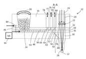
도 1은 기판 상에 솔더 볼들을 배치하기 위한 조립체의 수직 단면의 대략적인 도면이다.
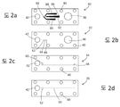
도 2a 내지 도 2d는, 도 1의 조립체 내에서 이용되는 시트 조립체의 시트들의 실시예들을 보여준다.
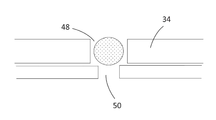
도 3은 도 2의 시트 조립체의 도 2d의 시트 내의 안내 슬릿의 효과들을 보여준다.
도 4는 도 1에 따라 솔더 볼들을 배치하기 위한 조립체 내의 배출 채널의 대략적인 표현이다.
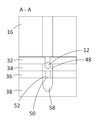
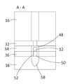
도 5는 흡인된 볼을 갖는 도 1의 단면 평면 A-A에 있어서의 수직 단면이다.
도 6은 방출된 볼을 갖는 도 1의 단면 평면 A-A에 있어서의 수직 단면이다.
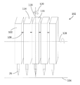
도 7은 수 개의 솔더 볼들을 동일한 시간 프레임 내에 배치하기 위한 복수의 모듈들을 갖는 조립체를 보여준다.
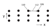
도 8은 복수의 모듈들을 갖는 모듈러 조립체를 가지고 기판 상에 배치되는 솔더 볼들의 대략적인 도면이다.
도 9는 수평 축 주위로 경사진 도 8의 모듈러 조립체를 가지고 기판 상에 배치되는 솔더 볼들의 대략적인 도면이다.
도 10은 수직 축 주위로 경사진 도 8의 모듈러 조립체를 가지고 기판 상에 배치되는 솔더 볼들의 대략적인 도면이다.
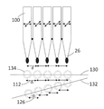
도 11은 모듈러 조립체가 수직 축 주위로 경사질 때 솔더 볼들 사이의 거리들이 어떻게 변하는지 보여준다.
도 12는 모듈러 조립체의 모듈들이 서로에 대하여 경사지는 것에 의해 솔더 볼들의 거리들이 어떻게 변할 수 있는지 보여준다.
도 13은 원하는 위치를 조정하기 위한 모듈의 경사의 정도를 보여준다. 1 is a schematic illustration of a vertical cross section of an assembly for placing solder balls on a substrate.
2A-2D show embodiments of sheets of the seat assembly used within the assembly of FIG. 1.
3 shows the effects of the guide slit in the seat of FIG. 2D of the seat assembly of FIG. 2.
4 is a schematic representation of the discharge channel in the assembly for placing solder balls according to FIG. 1.
FIG. 5 is a vertical section in section plane AA of FIG. 1 with a suctioned ball. FIG.
FIG. 6 is a vertical section in section plane AA of FIG. 1 with the ball released; FIG.
7 shows an assembly with a plurality of modules for placing several solder balls within the same time frame.
8 is a schematic diagram of solder balls disposed on a substrate with a modular assembly having a plurality of modules.
FIG. 9 is a schematic illustration of solder balls disposed on a substrate with the modular assembly of FIG. 8 inclined about a horizontal axis. FIG.
FIG. 10 is a schematic diagram of solder balls disposed on a substrate with the modular assembly of FIG. 8 inclined about a vertical axis. FIG.
11 shows how the distances between the solder balls change when the modular assembly is tilted around the vertical axis.
12 shows how the distances of the solder balls can be varied by inclining the modules of the modular assembly with respect to each other.
Figure 13 shows the degree of inclination of the module to adjust the desired position.
도 1은 참조부호 10으로 일반적으로 지시되는 결합 헤드(bond head)의 대략도이다. 더 잘 관찰하기 위해 결합 헤드(10)는 필수적인 제어 유닛 및 마운팅 없이 도시되어 있다. 하나의 이러한 결합 헤드가 기판(미도시) 상에 배치된다. 저장부(14)로부터의 솔더 볼들(12)은 이하에서 설명되는 방식으로 하나씩 배출되어 기판 상에 배치된다. 이러한 기판에 대한 일 예는 웨이퍼이다. 1 is a schematic representation of a bond head, generally indicated at 10. In order to better observe the
결합 헤드(10)는 블록(16)을 가진다. 본 실시예에 있어서 블록(16)은 알루미늄으로 만들어진다. 하지만, 다른 물질도 적합할 수 있음이 이해되어야 한다. 고가의, 단단한 물질들을 사용할 필요는 없다. 블록(16)은 필수적으로 입방형의 형태이지만, 유용하다면, 다른 외형을 가정할 수 있다. The
큰 캐버티가 저장부(14)로서 기능하는 블록(16) 내에 제공된다. 저장부(14)는 덮개(18)에 의해 밀폐된다. 블록(16)에는 나아가 넓은 쓰루 보어홀(20)이 마련된다. 쓰루 보어홀(20)은 배출 채널(30)의 일부로서 기능한다. 초점 렌즈(22)는 쓰루 보어홀(20) 내에 배치된다. 초점 렌즈(22) 또는 렌즈 조립체는 출구(26)의 범위 내에서 레이저 빔(24)을 포커싱하기 위해 제공된다. 레이저 빔(24)은 출구 내에 존재하는 솔더링 볼을 녹이기 위해 제공된다. Large cavities are provided in
블록(16)은 복수의 적층된 시트들(32, 34 및 36)의 시트 조립체에 연결된다. 시트들(32, 34 및 36)은 별도로 도 2b, 도 2c 및 도 2d에 도시되어 있다. 시트들(32, 34 및 36)을 갖는 시트 조립체는 블록(16)과 베이스(38) 사이에 놓인다. 모든 부품들은 알루미늄이나 또는 다른 적합한 물질로 만들어질 수 있다. 고정을 목적으로, 블록(16)과 시트 조립체의 시트들에는 이들의 모서리를 따라 보어홀들(40)이 마련되는데, 이것은 도 2에서 잘 알 수 있다. 보어홀들(40)은 본 실시예에서 제공된다. 나사는 베이스 내의 나사산 있는 보어로 완전히 꽉 나사조임되는 이러한 보어홀들을 통해 삽입될 수 있다. 나사의 머리는 블록(16) 내의 홈에 들어갈 수 있다.
시트들(32, 34 및 36) 각각에는 보어홀(42)이 마련된다. 각각의 시트의 보어홀(42)은 다른 시트들 내의 대응하는 보어홀들(42) 및 쓰루-보어홀(20)과 정렬된다. 베이스(38) 내의 대응하는 보어홀(44)과 함께 이들은 배출 채널(30)의 일부를 형성한다. Each of the
나아가, 시트(32)에는 넓은 보어홀(46)이 마련된다. 보어홀(46)은 저장부(14)를 형성하는 캐버티와 정렬되고 또한 거의 동일한 지름을 가진다. 이것은 도 1에서 잘 알 수 있다. 슬릿(48)은 시트(34) 내에 제공된다. 슬릿(48)은 저장부(14)로부터 출구(26)로 볼들(12)을 안내하는 공급 채널의 일부를 형성한다. 슬릿(48)은 보어홀(46) 아래로부터 보어홀(42)의 범위 바로 앞까지 연장된다. 슬릿(48)의 폭은 저장부(14)로부터 사용되는 볼들(12) 중 하나의 폭보다 더 크다. 볼들은 이때 슬릿(48)을 관통해 잘 움직일 수 있다. 하지만, 슬릿(48)의 폭은, 제2 볼(12)이 다른 볼을 지나는 것을 막기에 충분히 작다. 이러한 방식으로 단지 하나의 볼(12)은 슬릿(48)을 통해 하나의 위치를 따라 움직일 수 있다. 결론적으로, 볼들(12)은 하나씩 슬릿(48)을 통해 개별적으로 이동한다. Further, the
본 실시예에 있어서 볼들(12)은 슬릿(48)의 중심에서 안내된다. 이 목적을 위해 거의 동일한 길이를 갖는 슬릿(50)이 그 아래에 배치되는 시트(36) 내에 마련된다. 슬릿(50)은 볼(12)의 지름보다 더 작은 폭을 가진다. 이것은 도 3에서 잘 알 수 있다. 그러므로, 볼(12)은 슬릿(50)으로 들어가지 않지만 트랙 상에서와 같이 그 위로 안내된다. 이로써, 볼들(12)은 도 1에 대략적으로 도시된 바와 같이 슬릿(48)에 의해 형성되는 공급 채널 내의 슬릿(50) 상에서 연이어 이동한다. 저장부(14)로부터 먼 끝단(52)에서 슬릿(50)은 원형으로 넓어진다. 확장부(widening)는 볼(12)의 지름보다 더 크다. 그러므로, 볼(12)은 확장부(52)를 통해 아래쪽으로 움직일 수 있다. 이러한 확장부(60)는 또한 슬릿(48)의 끝단에 마련될 수 있다. 이로써, 아래쪽으로의 움직임이 제공된다. In this embodiment the
연결 채널(54)이 베이스(38) 내에 마련되고, 연결 채널(54)은 경사진 보어홀의 형태를 가진다. 이것은 도 1에서 특히 잘 알 수 있다. 연결 채널(54)은 확장부(52)와 그 위의 슬릿(48) 및 확장부(60)를 각각, 보어홀(44)과, 연결한다. 연결 채널(54)은 볼(12)의 지름보다 더 넓고, 이로써 볼은 공급 채널(48)로부터 확장부들(60 및 52) 및 연결 채널(54)을 통해 배출 채널(30)로 움직일 수 있다. A connecting
도 4는 도 1에서의 단면 평면에 90 도의 각도 만큼 상대적으로 회전된 수직 단면 평면을 따르는 배출 채널(30)을 관통하는 단면을 보여준다. 볼(12)을 가진 배출 채널(30) 앞의 연결 채널(54)의 끝 범위(56)를 볼 수 있다. 도 5 및 도 6은 슬릿들(48 및 50)의 길이방향으로 측면으로 천이된 단면을 보여준다. 연결 채널(54)의 입구 범위(58)를 볼 수 있다. 입구 범위(58)와 정렬된 확장부(52)의 위치는 도 5 및 도 6에서 볼 수 있다. FIG. 4 shows a cross section through the
시트(32)는 공급 채널(48)을 갖는 시트 상에 놓인다. 시트(32)에는 사용되는 볼들(12)의 지름보다 더 작은 지름을 가지는 3 개의 보어홀들(62, 64 및 66)이 마련된다. 이것은 도 1에서 알 수 있다. 보어홀들은 스케일업되면 도 2b에서 잘 볼 수 없을 수 있어, 증가된 스케일로 도시되어 있다. 보어홀들(62, 64 및 66)은 슬릿(48) 위에 길이방향으로 연속해서 천이되어 놓인다. 보어홀(62)은 슬릿들(48 및 50)의 확장된 범위들(60 및 52) 위 저장부(14)로부터 먼 슬릿(48)의 측 상에 마련된다. 보어홀들(64 및 66)은 저장부(14)에 근접한 슬릿들(48 및 50) 위의 범위에서 길이방향으로 천이된다. The
도 1은 대략적인 표현이다. 여기서, 보어홀들(62, 64 및 66)은 블록(16) 내의 수직 쓰루 보어홀들(68, 70 및 72)에서 끝난다. 쓰루 보어홀들(68, 70 및 72)은 보어홀들(62, 64 및 66) 각각을 대기에 연결한다. 제어가능한 밸브 또는 셔터(미도시)는 대기와의 연결을 제어한다. 이것은 화살표들(74, 76 및 78)에 의해 표현된다. 1 is an approximate representation. Here, the
블록(16)에는 측면 보어홀(80)이 마련된다. 보어홀(80)은 슬릿들(48 및 50)의 범위 내 및 보어홀(46)의 범위 내 내부에서 끝난다. 질소와 같은, 불활성 가스를 갖는 가스 소스는 보어홀(80)에 연결된다. 가스는 증가된 압력을 제공한다. 이러한 방식으로, 덮개(18)에 의해 닫히는 저장부(14), 슬릿들(48 및 50), 보어홀들(62, 64, 66, 68, 70 및 72) 및 보어홀(54)을 포함하는, 조립체의 전체 내부는, 증가된 압력에 노출된다. 밸브가 보어홀들(68, 70 또는 72) 중 하나에서 대기를 향해 열린다면, 압력 차가 생성된다. 슬릿들(48 및 50) 내의 압력은 보어홀들 내의 압력보다 더 크다. 따라서, 흡인 효과가 생성된다. 공급 채널 내의 볼은 열린 밸브를 갖는 보어홀을 지나갈 때 흡인된다. The
슬릿(48)에 의해 형성되는 공급 채널의 지름들은 볼(12)이 다른 볼을 지나갈 수 없도록 선택된다. 따라서, 흡인 효과로 인해 볼(12)이 보어홀(62, 64 또는 66)에 고정되면, 어떠한 볼들도 지나갈 수 없다. 공급 채널 내의 통로는 완전히 막히게 된다. 도 1은 볼이 보어홀들(62, 64 및 66) 각각에 고정되는 상황을 대략적으로 보여준다. The diameters of the feed channels formed by the
도 1에 대략도로 도시된 바와 같은 채널들(68, 70 및 72)의 제조는 어렵다. 보어홀들(62, 64 및 66)은 매우 작은 지름을 가지고 서로 근접한다. 제조는 시트(32) 상에 놓이는 다른 시트(82)를 추가하는 것에 의해 제조될 수 있다. 시트(82)는 또한 다른 시트들에 대하여 이미 위에서 설명된 바와 같은 보어홀들(40, 42 및 46)을 가진다. 나아가, 시트(82)는 3 개의 슬릿들(84, 86 및 88)을 가진다. 슬릿(84)은 보어홀(62) 상의 범위 내에서 그 출구 측 끝단(90)에서 끝난다. 슬릿(86)은 보어홀(64) 상의 범위 내에서 그 출구 측 끝단(90)에서 끝난다. 슬릿(88)은 보어홀(66) 상의 범위 내에서 그 출구 측 끝단(90)에서 끝난다. 슬릿들(84, 86 및 88)의 출구 측 끝단들(90)은 상대적으로 작아서 이로써 이들은 인접한 보어홀 상의 범위로 연장되지 않는다. 하지만, 그렇지 않다면, 슬릿들(84, 86 및 88)은 확장된다. 보어홀들(68, 70 및 72)과 유사하게 베이스(16)는 약간 더 넓은 보어홀들을 가지고 또한 그 측면으로부터 또는 그 위로부터 대기 측 상의 슬릿들(84, 86 및 88)의 다른 끝단(92)까지 연장된다. 이러한 슬릿들은 시트 내에 레이저를 이용해 쉽게 제조될 수 있다. 초음파 진동기(94)는 고주파를 이용해 조립체를 움직이도록 기능한다. 볼들(12)의 이동성은 진동기(94)를 이용해 개선된다. 이들은 걸리거나 또는 막히지 않을 것이다. The manufacture of
조립체는 이하와 같이 작동한다. The assembly works as follows.
솔더 볼들(12)은 덮개가 열릴 때 저장부(14)로 채워질 수 있다. 그후 저장부(14)는 덮개로 밀폐된다. 볼들(12)은 슬릿(48)으로 보어홀들(46)을 통해 아래쪽으로 떨어진다. 이때 그들은 오른쪽을 향해 움직일 것이다. 도 1은 공급 채널(48)이 필수적으로 수평인 조립체를 보여준다. 움직임은 압력 강하에 의해 야기된다. 출구 방향으로의 볼들의 이동을 개선시키기 위해 공급 채널(48)은 출구 방향으로 아래쪽으로 약간 경사져 있을 수 있다. 이것은 쐐기형태의 시트에 의해 또는 전체 조립체를 기울이는 것에 의해 달성될 수 있다. 볼들(12)은 도 3 및 도 6에서 잘 알 수 있는 바와 같이 공급 채널(48)의 중심에 있는 슬릿(50)에 의해 안내된다. The
먼저, 대기를 향하는 모든 밸브들이 열린다. 공급 채널(48)과 보어홀(62, 64 및 66) 사이의 전이 범위에서 볼들(12)은 압력 차로 인해 흡인된다. 이로써, 이들은 도 1에서 잘 볼 수 있는 바와 같이, 뒤따르는 볼들에 대한 통로를 막는다. First, all the valves to the atmosphere are opened. In the transition range between the
채널(68)에 있는 밸브가 닫히면, 볼은 보어홀(62)에 의해 방출된다. 이것은 중력으로 인해 연결 채널(54)로 떨어질 것이다. 연결 채널(54)로부터 볼(12)은 배출 채널(30)로 떨어질 것이다. 먼저, 볼은 출구(26)에 갇힐 것이다. 이로써, 출구(26)는 닫힌다. 증가된 압력은 출구 채널(30)에서 및 연결 채널(54)에서 생성된다. 압력 센서(미도시)는 연결 채널(54) 내의 압력을 측정한다. 연결 채널(54) 내의 압력 증가는 볼이 출구(26)의 범위 내에 존재함을 지시한다. When the valve in the
볼(12)이 출구(26)에 도달할 때 보어홀(68) 내의 밸브는 열린다. 보어홀(70) 내의 밸브는 닫힌다. 이로써, 고정된 볼들 중 중간 볼은 방출된다. 이것은 다음 보어홀(68)에서 흡인되고 고정된다. 이때 보어홀(70)에 있는 밸브는 다시 열리고 보어홀(72) 내의 밸브는 닫힌다. 저장부-측 보어홀(66) 앞에 고정된 볼은 방출되고 중간 보어홀(64)에 의해 흡인되어 거기에 고정된다. 보어홀(72) 내의 밸브가 다시 열린 때 공급 채널(48)로부터 새로운 볼이 보어홀(66) 앞에 고정된다. 이것은 뒤따르는 볼들의 이동을 막을 것이다. 이러한 방식으로 단지 하나의 볼만 한번에 출구(26)로 움직인다. The valve in the
레이저 빔(24)은 렌즈(22) 또는 렌즈 조립체를 가지고 배출 채널(30)로 포커싱된다. 출구(26) 내의 볼은 레이저 빔(24)의 초점 내에 놓인다. 레이저 빔의 에너지는 볼(12)이 솔더를 녹일 수 있도록 선택되고 솔더는 그 아래에 존재하는 기판 상에 배치된다. 출구는 솔더가 사용되어야 하는 이러한 위치에 정확히 위치되는 것이 이해되어야 한다. 조립체는 움직일 수 있는 부품을 사용하지 않는다. 솔더 볼을 배치하기 위한 속도는, 그러므로 밸브들이 닫히는 시간에 의해서만 제한된다. 이들은 디스크 등을 움직이는 데 필요한 시간보다 훨씬 더 작다. The
IR-센서는 솔더의 온도를 측정한다. 이러한 방식으로 레이저 활동은 제어될 수 있다. 반-투명 미러가 측면으로부터 배출 채널(30)로 레이저 광을 커플링 인하기 위한 이러한 목적을 위해 제공된다. 반-투명 미러는 IR 광을 위쪽으로 전달할 것이다. 레이저는 IR- 또는 VIS-레이저일 수 있다. IR sensors measure the temperature of the solder. In this way the laser activity can be controlled. A semi-transparent mirror is provided for this purpose for coupling in the laser light from the side to the
본 실시예에 있어서, 전체적으로 필수적으로 입방형 모듈러 블록(100)을 형성하는 조립체가 선택되었다. 단지 출구(26)는 아래쪽으로 연장되는 팁에 마련된다. 이것은 도 7에 대략적으로 도시된 바와 같이 나란히 수 개의 이러한 모듈들(100)을 배치하는 것을 가능하게 한다. 이러한 방식으로 형성되는 모듈러 조립체(102)는 기판(104)을 따라 움직일 수 있거나 또는 기판(104)이 모듈러 조립체(102) 아래로 움직인다. In this embodiment, an assembly was formed that essentially formed the cubic
도 8은 각각의 모듈(100)이 동시에 기판 상에 솔더 볼을 배치할 때 생성되는 패턴을 보여준다. 각각의 모듈을 제어하는 적절한 시간에 의해, 접촉 점들(106)의 위치는 y-방향으로, 즉 기판(14) 또는 모듈러 조립체(102)의 이동 방향으로, 원하는 방식으로 천이될 수 있음이 이해되어야 한다.8 shows a pattern generated when each
모듈러 조립체를 이용해 접촉 점들의 거리들은 x-방향으로 조정가능하다. 2 개의 접촉 점들(106 및 110) 사이의 거리(112)는, 예를 들어, 대응하는 모듈들(114 및 116)의 출구들의 거리에 의해 결정된다. 출구들은 모듈들(114 및 116)의 앞 범위 내에 있다. 모듈들(114 및/또는 116)이 작은 각 만큼 수직 축 주위로 회전되면, 모듈들(114 및 116)은 소정의 각을 형성한다. 이로써, 모듈들 사이의 거리(108)는 각각의 출구들의 범위 내에서 달라진다. Using the modular assembly the distances of the contact points are adjustable in the x-direction. The
수직 축 주위로 모듈의 이러한 개별적인 각 움직임들(angular movements)을 가능하게 해주는 각 범위는 컴팩트한 모듈러 조립체들로 한정된다. 이로써, 모듈(100) 사이의 작은 거리들을 이용해, 상황에 따라서는, 모든 범위들을 커버하는 것이 가능하지 않다. 그러므로, 전체 모듈러 조립체가 공통 축 주위로 회전되도록 구성하기 위해 본 조립체가 제공된다. 이것은 화살표(120)에 의해 도시되어 있다. 이 축(118) 주위로 회전할 때 출구들(26)은 움직임 방향에 수직한 행(124)과 정렬되지 않을 것이다. 대신 출구들의 행(124)은 90°가 아닌 모듈러 조립체 또는 기판(104)의 움직임(122) 방향과 각 α를 형성할 것이다. 이것은 도 9에 도시되어 있다. 이로써, 접촉 점들 사이의 거리(126)는 예를 들어 도 8에 도시된 바와 같이 최대 거리(112)에 대하여 감소된다. Each range that allows these individual angular movements of the module about the vertical axis is limited to compact modular assemblies. As such, it may not be possible to cover all ranges, depending on the situation, using small distances between
이러한 회전의 효과는 더 상세하게 다시 도 11에 도시되어 있다. 수 개의 출구들(26)은 하나의 행으로 정렬되는데, 이것은 선(130)에 의해 표현된다. 이 행 내에 놓인 솔더 볼들(134)은 d1에 의해 지정되는 거리(112)를 가진다. 모듈러 조립체가 도 7에서 볼 수 있는 바와 같은 각 만큼 회전되면 솔더 볼들은 행(132)으로 정렬된다. 이제 d2로 지정되는 d 방향으로의 거리(126)는 d1보다 더 작다. The effect of this rotation is again shown in FIG. 11 in more detail.
전체 모듈러 조립체의 회전은 모든 거리들이 동일한 방식으로 변하도록 야기시킨다. 하지만, 서로에 대하여 개별적인 모듈들을 경사지도록 하는 것도 가능하다. 도 12는 예를 들어, 거리(136)가 모듈(114)에 대하여 표현 평면에 수직한 수평 축 주위로 수직 평면으로부터 모듈(100)을 기울이는 것에 의해 어떻게 감소되는지 보여준다.Rotation of the entire modular assembly causes all distances to change in the same way. However, it is also possible to incline individual modules with respect to each other. 12 shows how distance 136 is reduced, for example, by tilting
공간에서 전반적으로 모듈러 조립체를 적절하게 안내하는 것에 의해 그리고 그 중에서 개별적인 모듈들을 안내하는 것에 의해 접촉 점의 위치의 조정이 가능함을 알 수 있다. 알려진 조립체들과 달리 기판의 큰 면적들은 솔더와 함께 실질적으로 동시에 적재될 수 있다. It can be seen that adjustment of the position of the contact point is possible by appropriately guiding the modular assembly throughout the space and by guiding the individual modules therein. Unlike known assemblies, large areas of the substrate can be loaded substantially simultaneously with the solder.
도 13의 측면도에서 볼 수 있는 바와 같이, 수평 축(128) 주위로 전체 모듈러 조립체의 회전은, 동일한 시간 해상도를 갖는 접촉 점들 사이의 작은 거리들을 가능하게 해준다. 이것은 도 10에 도시되어 있다. As can be seen in the side view of FIG. 13, the rotation of the entire modular assembly around the
단지 하나의 모듈들의 행이 사용되는 모듈러 조립체들만 사용될 수 있지 않음이 이해되어야 한다. 동일한 방식으로 복수의 모듈들이 움직임 방향으로 연속하여 배치될 수 있고 이로써 기판의 전체 영역들은 동시에 공급될 수 있다. It should be understood that only modular assemblies in which only one row of modules is used may be used. In the same way a plurality of modules can be arranged in succession in the direction of movement so that the entire areas of the substrate can be fed simultaneously.
Claims (12)
(a) 복수의 솔더 볼들(12)을 갖는 저장부(14);
(b) 단 하나의 솔더 볼(12)을 배출하기 위한 출구(26);
(c) 상기 저장부(14)로부터 상기 출구(26)까지 솔더 볼들(12)을 공급하기 위해 상기 저장부(14)와 상기 출구(26) 사이에 제공되는 공급 채널(48)을 포함하고,
(d) 상기 공급 채널(48)은 상기 사용된 솔더 볼들(12) 중 하나의 지름보다 더 크고 상기 사용된 솔더 볼들(12) 중 2 개의 지름보다 더 작은 지름을 갖는 개방 단면을 가지고;
(e) 상기 공급 채널(48) 내에서 끝나고 또한 상기 공급 채널(48)과 흡인 채널(68, 70, 72) 사이의 전이 범위(62, 64, 66) 내에, 상기 사용된 솔더 볼들(12) 중 하나의 단면보다 더 작은 단면을 가지는 흡인 채널(68, 70, 72);
(f) 상기 공급 채널(48)과 상기 흡인 채널(68, 70, 72) 사이에 압력 차를 생성하기 위한 수단, 이로써 상기 흡인 채널(68, 70, 72) 내의 압력은 상기 공급 채널(48) 내의 압력보다 더 작고 또한 상기 공급 채널(48) 내에 존재하는 솔더 볼(12)은 상기 흡인 채널(68, 70, 72)의 상기 전이 범위(62, 64, 66)에서 흡인될 수 있고; 및
(g) 적어도 하나의 솔더 볼(12)이 상기 흡인 채널(68, 70, 72)과 상기 공급 채널(48) 사이의 상기 전이 범위에서 제1 압력 차에서 저지되고 또한 추가적인 솔더 볼들(12)의 공급은 차단되고 제2 압력 차로 방출되는 방식으로, 압력 차를 제어하기 위한 제어 수단을 특징으로 하는, 조립체. In the assembly 100 for placing solder from solder balls 12 on a substrate 104,
(a) a reservoir 14 having a plurality of solder balls 12;
(b) an outlet 26 for discharging only one solder ball 12;
(c) a feed channel 48 provided between the reservoir 14 and the outlet 26 for supplying solder balls 12 from the reservoir 14 to the outlet 26,
(d) the supply channel 48 has an open cross section having a diameter larger than the diameter of one of the used solder balls 12 and smaller than the diameter of two of the used solder balls 12;
(e) the used solder balls 12 ending in the supply channel 48 and within the transition range 62, 64, 66 between the supply channel 48 and the suction channel 68, 70, 72. Suction channels 68, 70, 72 having a cross section smaller than one of the cross sections;
(f) means for creating a pressure difference between the feed channel 48 and the suction channels 68, 70, 72, such that the pressure in the suction channels 68, 70, 72 is reduced to the supply channel 48. Solder balls 12 that are less than the pressure within and present in the supply channel 48 can be sucked in the transition range 62, 64, 66 of the suction channel 68, 70, 72; And
(g) at least one solder ball 12 is blocked at a first pressure difference in the transition range between the suction channels 68, 70, 72 and the supply channel 48 and also the additional solder balls 12. And control means for controlling the pressure differential in such a way that the supply is interrupted and released into the second pressure differential.
Applications Claiming Priority (3)
| Application Number | Priority Date | Filing Date | Title |
|---|---|---|---|
| DE102017110830.0A DE102017110830A1 (en) | 2017-05-18 | 2017-05-18 | Arrangement and method for applying solder balls to a substrate |
| DE102017110830.0 | 2017-05-18 | ||
| PCT/EP2018/062571 WO2018210844A1 (en) | 2017-05-18 | 2018-05-15 | Assembly and method for applying solder balls to a substrate |
Publications (2)
| Publication Number | Publication Date |
|---|---|
| KR20200007796A true KR20200007796A (en) | 2020-01-22 |
| KR102475997B1 KR102475997B1 (en) | 2022-12-08 |
Family
ID=62167347
Family Applications (1)
| Application Number | Title | Priority Date | Filing Date |
|---|---|---|---|
| KR1020197032343A Active KR102475997B1 (en) | 2017-05-18 | 2018-05-15 | Assembly and method for placing solder balls on a substrate |
Country Status (7)
| Country | Link |
|---|---|
| US (1) | US20210379683A1 (en) |
| EP (1) | EP3624979B1 (en) |
| JP (1) | JP7121414B2 (en) |
| KR (1) | KR102475997B1 (en) |
| CN (1) | CN110740831B (en) |
| DE (1) | DE102017110830A1 (en) |
| WO (1) | WO2018210844A1 (en) |
Families Citing this family (8)
| Publication number | Priority date | Publication date | Assignee | Title |
|---|---|---|---|---|
| US11081458B2 (en) * | 2018-02-15 | 2021-08-03 | Micron Technology, Inc. | Methods and apparatuses for reflowing conductive elements of semiconductor devices |
| US11247285B1 (en) * | 2020-04-03 | 2022-02-15 | Seagate Technology Llc | Fluidization of agglomerated solder microspheres |
| DE102021112861A1 (en) | 2021-05-18 | 2022-11-24 | OSRAM Opto Semiconductors Gesellschaft mit beschränkter Haftung | SUPPORT STRUCTURE, METHOD OF MANUFACTURE OF SUPPORT STRUCTURE AND DEVICE AND PRINT HEAD FOR CARRYING OUT SUCH PROCESS |
| CN113385816B (en) * | 2021-07-28 | 2023-01-10 | 深圳市众心原激光科技有限公司 | Automatic plate laser welding device and welding method thereof |
| DE102022120336A1 (en) * | 2021-10-06 | 2023-04-06 | Pac Tech - Packaging Technologies Gmbh | Laser soldering device and solder application machine |
| KR20250039049A (en) * | 2023-09-13 | 2025-03-20 | 삼성전자주식회사 | Ball attach tool |
| WO2025054967A1 (en) * | 2023-09-15 | 2025-03-20 | Texas Instruments Incorporated | Ball mounting apparatus with ball attach volume control |
| CN118180531B (en) * | 2024-05-14 | 2024-08-06 | 湖南健坤精密科技有限公司 | Laser tin ball welding machine with flattening and correcting functions and correcting method |
Citations (2)
| Publication number | Priority date | Publication date | Assignee | Title |
|---|---|---|---|---|
| JP2008100830A (en) * | 2006-10-20 | 2008-05-01 | Shinapex Co Ltd | Powder and grain separating device and powder and grain separating unit |
| JP2011115819A (en) * | 2009-12-02 | 2011-06-16 | Hitachi Global Storage Technologies Netherlands Bv | Method for manufacturing head gimbal assembly, and apparatus for connecting connection pads thereof to each other |
Family Cites Families (5)
| Publication number | Priority date | Publication date | Assignee | Title |
|---|---|---|---|---|
| DE19544929C2 (en) * | 1995-12-01 | 2001-02-15 | Fraunhofer Ges Forschung | Device for the flux-free application of a solder to a substrate or a chip |
| JP4143795B2 (en) * | 2000-06-30 | 2008-09-03 | 澁谷工業株式会社 | Ball inspection method |
| JP2005081406A (en) * | 2003-09-10 | 2005-03-31 | Tdk Corp | Solder ball joining method and joining apparatus |
| JP4042914B2 (en) * | 2005-04-22 | 2008-02-06 | Tdk株式会社 | Soldering apparatus and solder distribution apparatus |
| JP4993418B2 (en) * | 2009-01-15 | 2012-08-08 | Tdk株式会社 | Conductive ball supply apparatus and method |
-
2017
- 2017-05-18 DE DE102017110830.0A patent/DE102017110830A1/en not_active Ceased
-
2018
- 2018-05-15 WO PCT/EP2018/062571 patent/WO2018210844A1/en not_active Ceased
- 2018-05-15 CN CN201880032374.8A patent/CN110740831B/en active Active
- 2018-05-15 JP JP2020514328A patent/JP7121414B2/en active Active
- 2018-05-15 KR KR1020197032343A patent/KR102475997B1/en active Active
- 2018-05-15 EP EP18724870.3A patent/EP3624979B1/en active Active
- 2018-05-15 US US16/614,235 patent/US20210379683A1/en not_active Abandoned
Patent Citations (2)
| Publication number | Priority date | Publication date | Assignee | Title |
|---|---|---|---|---|
| JP2008100830A (en) * | 2006-10-20 | 2008-05-01 | Shinapex Co Ltd | Powder and grain separating device and powder and grain separating unit |
| JP2011115819A (en) * | 2009-12-02 | 2011-06-16 | Hitachi Global Storage Technologies Netherlands Bv | Method for manufacturing head gimbal assembly, and apparatus for connecting connection pads thereof to each other |
Also Published As
| Publication number | Publication date |
|---|---|
| EP3624979B1 (en) | 2023-08-02 |
| KR102475997B1 (en) | 2022-12-08 |
| CN110740831A (en) | 2020-01-31 |
| EP3624979C0 (en) | 2023-08-02 |
| EP3624979A1 (en) | 2020-03-25 |
| WO2018210844A1 (en) | 2018-11-22 |
| JP7121414B2 (en) | 2022-08-18 |
| US20210379683A1 (en) | 2021-12-09 |
| CN110740831B (en) | 2022-03-25 |
| JP2020520561A (en) | 2020-07-09 |
| DE102017110830A1 (en) | 2018-11-22 |
Similar Documents
| Publication | Publication Date | Title |
|---|---|---|
| KR102475997B1 (en) | Assembly and method for placing solder balls on a substrate | |
| KR102409763B1 (en) | Transfering apparatus and transfering method | |
| US10227180B2 (en) | Robotic placement machine for optical bonding, system and method of use thereof | |
| US7164097B2 (en) | Solder ball bonding method and bonding device | |
| KR101963216B1 (en) | Solder ball feeder | |
| US11712881B2 (en) | Machine for optical bonding, system and method of use thereof | |
| JP2020520561A5 (en) | ||
| CN1767727B (en) | Conductive ball bonding method and conductive ball bonding apparatus | |
| CN114559124A (en) | Tin ball laser jetting device | |
| KR101981516B1 (en) | Component mounting device | |
| JP2022155471A (en) | Substrate to be transferred and transfer device | |
| KR101930422B1 (en) | Rotating assist gas supply | |
| EP0905064B1 (en) | Article conveyor | |
| KR101355246B1 (en) | Conductive ball arraying apparatus | |
| JP4915618B2 (en) | Conductive ball array device | |
| TWI884367B (en) | Bonding apparatus | |
| JP6547968B2 (en) | Component mounting device | |
| JP4479556B2 (en) | Laser etching equipment | |
| KR20240082129A (en) | Apparatus for manufacturing semiconductor devices and method of manufacturing semiconductor devices | |
| JP4793689B2 (en) | Conductive ball array device | |
| CN116921856A (en) | Welding equipment of electronic device | |
| JP2007299835A (en) | Conductive ball array device |
Legal Events
| Date | Code | Title | Description |
|---|---|---|---|
| PA0105 | International application |
St.27 status event code: A-0-1-A10-A15-nap-PA0105 |
|
| PG1501 | Laying open of application |
St.27 status event code: A-1-1-Q10-Q12-nap-PG1501 |
|
| A201 | Request for examination | ||
| P11-X000 | Amendment of application requested |
St.27 status event code: A-2-2-P10-P11-nap-X000 |
|
| P13-X000 | Application amended |
St.27 status event code: A-2-2-P10-P13-nap-X000 |
|
| PA0201 | Request for examination |
St.27 status event code: A-1-2-D10-D11-exm-PA0201 |
|
| D13-X000 | Search requested |
St.27 status event code: A-1-2-D10-D13-srh-X000 |
|
| D14-X000 | Search report completed |
St.27 status event code: A-1-2-D10-D14-srh-X000 |
|
| E902 | Notification of reason for refusal | ||
| PE0902 | Notice of grounds for rejection |
St.27 status event code: A-1-2-D10-D21-exm-PE0902 |
|
| P11-X000 | Amendment of application requested |
St.27 status event code: A-2-2-P10-P11-nap-X000 |
|
| P13-X000 | Application amended |
St.27 status event code: A-2-2-P10-P13-nap-X000 |
|
| E701 | Decision to grant or registration of patent right | ||
| PE0701 | Decision of registration |
St.27 status event code: A-1-2-D10-D22-exm-PE0701 |
|
| GRNT | Written decision to grant | ||
| PR0701 | Registration of establishment |
St.27 status event code: A-2-4-F10-F11-exm-PR0701 |
|
| PR1002 | Payment of registration fee |
St.27 status event code: A-2-2-U10-U12-oth-PR1002 Fee payment year number: 1 |
|
| PG1601 | Publication of registration |
St.27 status event code: A-4-4-Q10-Q13-nap-PG1601 |
|
| PN2301 | Change of applicant |
St.27 status event code: A-5-5-R10-R11-asn-PN2301 |
|
| PN2301 | Change of applicant |
St.27 status event code: A-5-5-R10-R14-asn-PN2301 |
|
| PR1001 | Payment of annual fee |
St.27 status event code: A-4-4-U10-U11-oth-PR1001 Fee payment year number: 4 |
|
| U11 | Full renewal or maintenance fee paid |
Free format text: ST27 STATUS EVENT CODE: A-4-4-U10-U11-OTH-PR1001 (AS PROVIDED BY THE NATIONAL OFFICE) Year of fee payment: 4 |