KR20200022505A - 와이어-기판 연결용 단자 - Google Patents
와이어-기판 연결용 단자 Download PDFInfo
- Publication number
- KR20200022505A KR20200022505A KR1020207003944A KR20207003944A KR20200022505A KR 20200022505 A KR20200022505 A KR 20200022505A KR 1020207003944 A KR1020207003944 A KR 1020207003944A KR 20207003944 A KR20207003944 A KR 20207003944A KR 20200022505 A KR20200022505 A KR 20200022505A
- Authority
- KR
- South Korea
- Prior art keywords
- base
- leg
- crimp
- circuit board
- wire
- Prior art date
- Legal status (The legal status is an assumption and is not a legal conclusion. Google has not performed a legal analysis and makes no representation as to the accuracy of the status listed.)
- Granted
Links
Images





Classifications
-
- H—ELECTRICITY
- H01—ELECTRIC ELEMENTS
- H01R—ELECTRICALLY-CONDUCTIVE CONNECTIONS; STRUCTURAL ASSOCIATIONS OF A PLURALITY OF MUTUALLY-INSULATED ELECTRICAL CONNECTING ELEMENTS; COUPLING DEVICES; CURRENT COLLECTORS
- H01R12/00—Structural associations of a plurality of mutually-insulated electrical connecting elements, specially adapted for printed circuits, e.g. printed circuit boards [PCB], flat or ribbon cables, or like generally planar structures, e.g. terminal strips, terminal blocks; Coupling devices specially adapted for printed circuits, flat or ribbon cables, or like generally planar structures; Terminals specially adapted for contact with, or insertion into, printed circuits, flat or ribbon cables, or like generally planar structures
- H01R12/70—Coupling devices
- H01R12/71—Coupling devices for rigid printing circuits or like structures
- H01R12/75—Coupling devices for rigid printing circuits or like structures connecting to cables except for flat or ribbon cables
-
- H—ELECTRICITY
- H01—ELECTRIC ELEMENTS
- H01R—ELECTRICALLY-CONDUCTIVE CONNECTIONS; STRUCTURAL ASSOCIATIONS OF A PLURALITY OF MUTUALLY-INSULATED ELECTRICAL CONNECTING ELEMENTS; COUPLING DEVICES; CURRENT COLLECTORS
- H01R4/00—Electrically-conductive connections between two or more conductive members in direct contact, i.e. touching one another; Means for effecting or maintaining such contact; Electrically-conductive connections having two or more spaced connecting locations for conductors and using contact members penetrating insulation
- H01R4/10—Electrically-conductive connections between two or more conductive members in direct contact, i.e. touching one another; Means for effecting or maintaining such contact; Electrically-conductive connections having two or more spaced connecting locations for conductors and using contact members penetrating insulation effected solely by twisting, wrapping, bending, crimping, or other permanent deformation
- H01R4/18—Electrically-conductive connections between two or more conductive members in direct contact, i.e. touching one another; Means for effecting or maintaining such contact; Electrically-conductive connections having two or more spaced connecting locations for conductors and using contact members penetrating insulation effected solely by twisting, wrapping, bending, crimping, or other permanent deformation by crimping
- H01R4/183—Electrically-conductive connections between two or more conductive members in direct contact, i.e. touching one another; Means for effecting or maintaining such contact; Electrically-conductive connections having two or more spaced connecting locations for conductors and using contact members penetrating insulation effected solely by twisting, wrapping, bending, crimping, or other permanent deformation by crimping for cylindrical elongated bodies, e.g. cables having circular cross-section
- H01R4/184—Electrically-conductive connections between two or more conductive members in direct contact, i.e. touching one another; Means for effecting or maintaining such contact; Electrically-conductive connections having two or more spaced connecting locations for conductors and using contact members penetrating insulation effected solely by twisting, wrapping, bending, crimping, or other permanent deformation by crimping for cylindrical elongated bodies, e.g. cables having circular cross-section comprising a U-shaped wire-receiving portion
- H01R4/185—Electrically-conductive connections between two or more conductive members in direct contact, i.e. touching one another; Means for effecting or maintaining such contact; Electrically-conductive connections having two or more spaced connecting locations for conductors and using contact members penetrating insulation effected solely by twisting, wrapping, bending, crimping, or other permanent deformation by crimping for cylindrical elongated bodies, e.g. cables having circular cross-section comprising a U-shaped wire-receiving portion combined with a U-shaped insulation-receiving portion
-
- H—ELECTRICITY
- H01—ELECTRIC ELEMENTS
- H01R—ELECTRICALLY-CONDUCTIVE CONNECTIONS; STRUCTURAL ASSOCIATIONS OF A PLURALITY OF MUTUALLY-INSULATED ELECTRICAL CONNECTING ELEMENTS; COUPLING DEVICES; CURRENT COLLECTORS
- H01R12/00—Structural associations of a plurality of mutually-insulated electrical connecting elements, specially adapted for printed circuits, e.g. printed circuit boards [PCB], flat or ribbon cables, or like generally planar structures, e.g. terminal strips, terminal blocks; Coupling devices specially adapted for printed circuits, flat or ribbon cables, or like generally planar structures; Terminals specially adapted for contact with, or insertion into, printed circuits, flat or ribbon cables, or like generally planar structures
- H01R12/50—Fixed connections
- H01R12/51—Fixed connections for rigid printed circuits or like structures
- H01R12/53—Fixed connections for rigid printed circuits or like structures connecting to cables except for flat or ribbon cables
-
- H—ELECTRICITY
- H01—ELECTRIC ELEMENTS
- H01R—ELECTRICALLY-CONDUCTIVE CONNECTIONS; STRUCTURAL ASSOCIATIONS OF A PLURALITY OF MUTUALLY-INSULATED ELECTRICAL CONNECTING ELEMENTS; COUPLING DEVICES; CURRENT COLLECTORS
- H01R12/00—Structural associations of a plurality of mutually-insulated electrical connecting elements, specially adapted for printed circuits, e.g. printed circuit boards [PCB], flat or ribbon cables, or like generally planar structures, e.g. terminal strips, terminal blocks; Coupling devices specially adapted for printed circuits, flat or ribbon cables, or like generally planar structures; Terminals specially adapted for contact with, or insertion into, printed circuits, flat or ribbon cables, or like generally planar structures
- H01R12/50—Fixed connections
- H01R12/51—Fixed connections for rigid printed circuits or like structures
- H01R12/55—Fixed connections for rigid printed circuits or like structures characterised by the terminals
- H01R12/58—Fixed connections for rigid printed circuits or like structures characterised by the terminals terminals for insertion into holes
-
- H—ELECTRICITY
- H01—ELECTRIC ELEMENTS
- H01R—ELECTRICALLY-CONDUCTIVE CONNECTIONS; STRUCTURAL ASSOCIATIONS OF A PLURALITY OF MUTUALLY-INSULATED ELECTRICAL CONNECTING ELEMENTS; COUPLING DEVICES; CURRENT COLLECTORS
- H01R12/00—Structural associations of a plurality of mutually-insulated electrical connecting elements, specially adapted for printed circuits, e.g. printed circuit boards [PCB], flat or ribbon cables, or like generally planar structures, e.g. terminal strips, terminal blocks; Coupling devices specially adapted for printed circuits, flat or ribbon cables, or like generally planar structures; Terminals specially adapted for contact with, or insertion into, printed circuits, flat or ribbon cables, or like generally planar structures
- H01R12/70—Coupling devices
- H01R12/7082—Coupling device supported only by cooperation with PCB
-
- H—ELECTRICITY
- H01—ELECTRIC ELEMENTS
- H01R—ELECTRICALLY-CONDUCTIVE CONNECTIONS; STRUCTURAL ASSOCIATIONS OF A PLURALITY OF MUTUALLY-INSULATED ELECTRICAL CONNECTING ELEMENTS; COUPLING DEVICES; CURRENT COLLECTORS
- H01R4/00—Electrically-conductive connections between two or more conductive members in direct contact, i.e. touching one another; Means for effecting or maintaining such contact; Electrically-conductive connections having two or more spaced connecting locations for conductors and using contact members penetrating insulation
- H01R4/02—Soldered or welded connections
- H01R4/023—Soldered or welded connections between cables or wires and terminals
-
- H—ELECTRICITY
- H01—ELECTRIC ELEMENTS
- H01R—ELECTRICALLY-CONDUCTIVE CONNECTIONS; STRUCTURAL ASSOCIATIONS OF A PLURALITY OF MUTUALLY-INSULATED ELECTRICAL CONNECTING ELEMENTS; COUPLING DEVICES; CURRENT COLLECTORS
- H01R4/00—Electrically-conductive connections between two or more conductive members in direct contact, i.e. touching one another; Means for effecting or maintaining such contact; Electrically-conductive connections having two or more spaced connecting locations for conductors and using contact members penetrating insulation
- H01R4/10—Electrically-conductive connections between two or more conductive members in direct contact, i.e. touching one another; Means for effecting or maintaining such contact; Electrically-conductive connections having two or more spaced connecting locations for conductors and using contact members penetrating insulation effected solely by twisting, wrapping, bending, crimping, or other permanent deformation
- H01R4/18—Electrically-conductive connections between two or more conductive members in direct contact, i.e. touching one another; Means for effecting or maintaining such contact; Electrically-conductive connections having two or more spaced connecting locations for conductors and using contact members penetrating insulation effected solely by twisting, wrapping, bending, crimping, or other permanent deformation by crimping
-
- H—ELECTRICITY
- H01—ELECTRIC ELEMENTS
- H01R—ELECTRICALLY-CONDUCTIVE CONNECTIONS; STRUCTURAL ASSOCIATIONS OF A PLURALITY OF MUTUALLY-INSULATED ELECTRICAL CONNECTING ELEMENTS; COUPLING DEVICES; CURRENT COLLECTORS
- H01R4/00—Electrically-conductive connections between two or more conductive members in direct contact, i.e. touching one another; Means for effecting or maintaining such contact; Electrically-conductive connections having two or more spaced connecting locations for conductors and using contact members penetrating insulation
- H01R4/24—Connections using contact members penetrating or cutting insulation or cable strands
- H01R4/2495—Insulation penetration combined with permanent deformation of the contact member, e.g. crimping
-
- H—ELECTRICITY
- H01—ELECTRIC ELEMENTS
- H01R—ELECTRICALLY-CONDUCTIVE CONNECTIONS; STRUCTURAL ASSOCIATIONS OF A PLURALITY OF MUTUALLY-INSULATED ELECTRICAL CONNECTING ELEMENTS; COUPLING DEVICES; CURRENT COLLECTORS
- H01R12/00—Structural associations of a plurality of mutually-insulated electrical connecting elements, specially adapted for printed circuits, e.g. printed circuit boards [PCB], flat or ribbon cables, or like generally planar structures, e.g. terminal strips, terminal blocks; Coupling devices specially adapted for printed circuits, flat or ribbon cables, or like generally planar structures; Terminals specially adapted for contact with, or insertion into, printed circuits, flat or ribbon cables, or like generally planar structures
- H01R12/50—Fixed connections
- H01R12/51—Fixed connections for rigid printed circuits or like structures
- H01R12/55—Fixed connections for rigid printed circuits or like structures characterised by the terminals
- H01R12/58—Fixed connections for rigid printed circuits or like structures characterised by the terminals terminals for insertion into holes
- H01R12/585—Terminals having a press fit or a compliant portion and a shank passing through a hole in the printed circuit board
Landscapes
- Coupling Device And Connection With Printed Circuit (AREA)
- Multi-Conductor Connections (AREA)
Abstract
Description
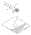
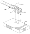
도 1은 단자 어셈블리의 실시형태의 사시도이다.
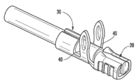
도 2는 도 1에 묘사된 크림프된(crimped) 단자의, 크림프된 단자가 회로 기판과 분리된 상태에서의 사시도이다.
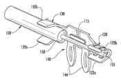
도 3은 도 2의 크림프된 단자의 사시도이다.
도 4는 도 3의 크림프되지 않은(un-crimped) 단자의 사시도이다.
도 5는 단자의 사시도이다.
도 6a는 도 5의 단자의 평면도이다.
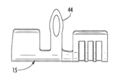
도 6b는 도 5의 단자의 측면도이다.
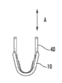
도 6c는 도 5의 단자의 정면도이다.
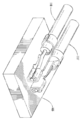
도 7은 단자 어셈블리의 제2의 실시형태의 사시도이다.
도 8은 도 7에 묘사된 크림프된 단자의, 크림프된 단자가 회로 기판과 분리된 상태에서의 사시도이다.
도 9는 도 8의 크림프되지 않은 단자의 사시도이다.
도 10은 도 8의 단자의 분해 사시도이다.
도 11은 단자 어셈블리의 실시형태의 사시도이다.
Claims (19)
- 단자이며,
양측에 제1 단부 및 제2 단부를 갖는 베이스,
상기 제1 단부에 근접하고 상기 베이스로부터 외측으로 연장된 제1 크림프부로서, 와이어의 노출된 도체에 맞물리도록 구성된 제1 크림프부;
상기 제2 단부에 근접하고 상기 베이스로부터 외측으로 연장된 제2 크림프부로서, 와이어의 절연층에 맞물리도록 구성된 제2 크림프부; 및
상기 베이스로부터 외측으로 연장된 제1의 다리 및 제2의 다리를 포함하고,
상기 제1의 다리는 회로 기판의 대응되는 제1 개구 안으로 연장되도록 구성되고, 상기 제2의 다리는 상기 회로 기판의 대응되는 제2 개구 안으로 연장되도록 구성되는, 단자. - 청구항 1에 있어서,
상기 제1의 다리 및 제2의 다리 각각은 미부를 포함하고,
상기 제1의 다리 및 제2의 다리 각각의 미부는 바늘귀 구조를 갖고,
상기 미부는 상기 회로 기판의 대응되는 개구 안으로 압입(press-fit)되도록 구성된, 단자. - 청구항 1에 있어서,
상기 제1 크림프부는 상기 와이어의 노출된 도체의 양측의 주위로 연장되어 접히도록 구성된 제1 날개 및 제2 날개로 형성되는, 단자. - 청구항 1에 있어서,
상기 제2 크림프부는 상기 와이어의 절연층의 양측의 주위로 연장되어 접히도록 구성된 제1 날개 및 제2 날개로 형성되는, 단자. - 청구항 1에 있어서,
상기 제1의 다리 및 제2의 다리는 제1 크림프부 및 제2 크림프부 사이에서 상기 베이스로부터 외측으로 연장되고,
상기 제1 크림프부 및 제2 크림프부는 상기 베이스로부터 외측으로 연장되는, 단자. - 청구항 1에 있어서,
상기 베이스는 마주하는 제1 및 제2 측부를 갖고,
상기 제1의 다리는 상기 베이스의 제1 측부로부터 외측으로 연장되고,
상기 제2의 다리는 상기 베이스의 제2 측부로부터 외측으로 연장되고,
상기 제1 및 제2 크림프부와 제1의 다리 및 제2의 다리는 각각 대체로 수직으로 상기 베이스로부터 외측으로 연장되는, 단자. - 청구항 1에 있어서,
상기 베이스는 측부를 갖고,
상기 제1의 다리 및 제2의 다리 각각은 상기 베이스의 측부로부터 외측으로 연장되고,
상기 제1 및 제2 크림프부 각각은 대체로 수직으로 상기 베이스로부터 외측으로 연장되고,
상기 제1의 다리 및 제2의 다리 각각은 대체로 수직으로 상기 베이스로부터 외측으로 연장되는, 단자. - 와이어 조립체이며,
도체를 덮는 절연층을 갖는 와이어, 및
베이스, 제1 및 제2 크림프부, 제1의 다리 및 제2의 다리를 갖는 단자를 포함하고,
상기 와이어는 제1 부분 및 제2 부분을 갖고, 제1 부분은 도체와 절연층으로 형성되고, 제2 부분은 도체 만으로 형성되고,
상기 베이스는 양측에 제1 단부 및 제2 단부를 갖고,
상기 제1 크림프부는 상기 제1 단부에 근접하고 상기 베이스로부터 외측으로 연장되고, 상기 와이어의 제2 부분에 맞물리도록 구성되고,
상기 제2 크림프부는 상기 제2 단부에 근접하고 상기 베이스로부터 외측으로 연장되고, 상기 와이어의 제1 부분에 맞물리도록 구성되고,
상기 제1의 다리 및 제2의 다리는 상기 베이스로부터 외측으로 연장되고,
상기 제1의 다리는 회로 기판의 대응되는 제1 개구 안으로 연장되도록 구성되고, 상기 제2의 다리는 상기 회로 기판의 대응되는 제2 개구 안으로 연장되도록 구성되는,
와이어 조립체. - 청구항 8에 있어서,
상기 제1의 다리 및 제2의 다리 각각은 미부를 포함하고,
상기 제1의 다리 및 제2의 다리 각각의 미부는 바늘귀 구조를 갖고,
상기 미부는 상기 회로 기판의 대응되는 적어도 하나의 개구 안으로 압입(press-fit)되도록 구성된, 와이어 조립체. - 청구항 8에 있어서,
상기 제1 크림프부는 상기 와이어의 제2 부분의 양측의 주위로 연장되어 접히도록 구성된 제1 날개 및 제2 날개로 형성되고,
상기 제2 크림프부는 상기 와이어의 제1 부분의 양측의 주위로 연장되어 접히도록 구성된 제1 날개 및 제2 날개로 형성되는, 와이어 조립체 - 청구항 8에 있어서,
상기 제1의 다리 및 제2의 다리는 제1 크림프부 및 제2 크림프부 사이에서 상기 베이스로부터 외측으로 연장되고,
상기 제1 크림프부 및 제2 크림프부는 상기 베이스로부터 외측으로 연장되는, 와이어 조립체. - 청구항 8에 있어서,
상기 베이스는 마주하는 제1 및 제2 측부를 갖고,
상기 제1의 다리는 상기 베이스의 제1 측부로부터 외측으로 연장되고,
상기 제2의 다리는 상기 베이스의 제2 측부로부터 외측으로 연장되고,
상기 제1 및 제2 크림프부와 제1의 다리 및 제2의 다리는 각각 대체로 수직으로 상기 베이스로부터 외측으로 연장되는, 와이어 조립체. - 청구항 8에 있어서,
상기 베이스는 측부를 갖고,
상기 제1의 다리 및 제2의 다리 각각은 상기 베이스의 측부로부터 외측으로 연장되고,
상기 제1 및 제2 크림프부 각각은 대체로 수직으로 상기 베이스로부터 외측으로 연장되고,
상기 제1의 다리 및 제2의 다리 각각은 상기 베이스로부터 대체로 평행하게 외측으로 연장되는, 와이어 조립체. - 조립체이며,
지지 표면, 제1 개구 및 제2 개구를 갖는 회로 기판, 및
와이어 및 단자를 포함하는 와이어 조립체를 포함하고,
상기 와이어는 도체를 덮는 절연층을 갖고,
상기 와이어는 제1 부분 및 제2 부분을 갖고, 제1 부분은 도체와 절연층으로 형성되고, 제2 부분은 도체 만으로 형성되고,
상기 단자는 베이스, 제1 및 제2 크림프부, 제1의 다리 및 제2의 다리를 갖고,
상기 베이스는 양측에 제1 단부 및 제2 단부를 갖고,
상기 제1 크림프부는 상기 제1 단부에 근접하고 상기 베이스로부터 외측으로 연장되고, 상기 제1 크림프부는 상기 와이어의 제2 부분에 맞물리도록 구성되고, 상기 제1 크림프부는 상기 회로 기판의 지지 표면으로부터 이격되어 있고,
상기 제2 크림프부는 상기 제2 단부에 근접하고 상기 베이스로부터 외측으로 연장되고, 상기 제2 크림프부는 상기 와이어의 제1 부분에 맞물리도록 구성되고,
상기 제2 크림프부는 상기 회로 기판의 지지 표면에 위치하고,
상기 제1의 다리 및 제2의 다리는 상기 베이스로부터 외측으로 연장되고,
상기 제1의 다리는 상기 회로 기판의 제1 개구 안으로 연장되고,
상기 제2의 다리는 상기 회로 기판의 제2 개구 안으로 연장되는,
조립체. - 청구항 14에 있어서,
상기 제1의 다리 및 제2의 다리 각각은 미부를 포함하고,
상기 제1의 다리 및 제2의 다리 각각의 미부는 바늘귀 구조를 갖고,
상기 미부는 상기 회로 기판의 적어도 하나의 개구 안으로 압입(press-fit)되도록 구성된, 조립체. - 청구항 14에 있어서,
상기 제1 크림프부는 상기 와이어의 제2 부분의 양측의 주위로 연장되어 접히도록 구성된 제1 날개 및 제2 날개로 형성되고,
상기 제2 크림프부는 상기 와이어의 제1 부분의 양측의 주위로 연장되어 접히도록 구성된 제1 날개 및 제2 날개로 형성되는, 조립체 - 청구항 14에 있어서,
상기 제1의 다리 및 제2의 다리는 제1 크림프부 및 제2 크림프부 사이에서 상기 베이스로부터 외측으로 연장되고,
상기 제1 크림프부 및 제2 크림프부는 상기 베이스로부터 외측으로 연장되는, 조립체. - 청구항 14에 있어서,
상기 베이스는 상기 회로 기판의 지지 표면에 대체로 평행하고,
상기 베이스는 마주하는 제1 및 제2 측부를 갖고,
상기 제1의 다리는 상기 회로 기판의 지지 표면을 향해 대체로 수직으로 상기 베이스의 제1 측부로부터 외부로 연장하고,
상기 제2의 다리는 상기 회로 기판의 지지 표면을 향해 대체로 수직으로 상기 베이스의 제2 측부로부터 외부로 연장하고,
상기 제1 및 제2 크림프부 각각은 상기 회로 기판의 지지 표면을 향해 대체로 수직으로 상기 베이스로부터 외측으로 연장되는, 조립체. - 청구항 14에 있어서,
상기 베이스는 상기 회로 기판의 지지 표면에 대체로 수직이고,
상기 베이스는 상기 회로 기판의 지지 표면을 마주하는 측부를 갖고,
상기 제1의 다리 및 제2의 다리 각각은 상기 회로 기판의 지지 표면을 향해 대체로 평행하게 상기 베이스의 측부로부터 외부로 연장하고,
상기 제1 및 제2 크림프부 각각은 대체로 수직으로 상기 베이스로부터 외측으로 연장되어, 상기 제1 및 제2 크림프부가 상기 회로 기판의 지지 표면에 대체로 평행인, 조립체.
Applications Claiming Priority (5)
| Application Number | Priority Date | Filing Date | Title |
|---|---|---|---|
| US201261730385P | 2012-11-27 | 2012-11-27 | |
| US61/730,385 | 2012-11-27 | ||
| US201361825666P | 2013-05-21 | 2013-05-21 | |
| US61/825,666 | 2013-05-21 | ||
| PCT/US2013/072012 WO2014085458A1 (en) | 2012-11-27 | 2013-11-26 | Wire to board terminal |
Related Parent Applications (1)
| Application Number | Title | Priority Date | Filing Date |
|---|---|---|---|
| KR1020157016861A Division KR102173544B1 (ko) | 2012-11-27 | 2013-11-26 | 와이어-기판 연결용 단자 |
Publications (2)
| Publication Number | Publication Date |
|---|---|
| KR20200022505A true KR20200022505A (ko) | 2020-03-03 |
| KR102188671B1 KR102188671B1 (ko) | 2020-12-08 |
Family
ID=50828417
Family Applications (2)
| Application Number | Title | Priority Date | Filing Date |
|---|---|---|---|
| KR1020207003944A Expired - Fee Related KR102188671B1 (ko) | 2012-11-27 | 2013-11-26 | 와이어-기판 연결용 단자 |
| KR1020157016861A Expired - Fee Related KR102173544B1 (ko) | 2012-11-27 | 2013-11-26 | 와이어-기판 연결용 단자 |
Family Applications After (1)
| Application Number | Title | Priority Date | Filing Date |
|---|---|---|---|
| KR1020157016861A Expired - Fee Related KR102173544B1 (ko) | 2012-11-27 | 2013-11-26 | 와이어-기판 연결용 단자 |
Country Status (6)
| Country | Link |
|---|---|
| US (2) | US9362630B2 (ko) |
| KR (2) | KR102188671B1 (ko) |
| CN (1) | CN104995801B (ko) |
| MY (1) | MY169412A (ko) |
| TW (1) | TWI508385B (ko) |
| WO (1) | WO2014085458A1 (ko) |
Families Citing this family (11)
| Publication number | Priority date | Publication date | Assignee | Title |
|---|---|---|---|---|
| WO2014085458A1 (en) * | 2012-11-27 | 2014-06-05 | Molex Incorporated | Wire to board terminal |
| CN104124543A (zh) * | 2014-07-30 | 2014-10-29 | 株洲天利铁路机车车辆配件有限公司 | 一种压接转焊接电路板连接方法及接线端子 |
| JP6621450B2 (ja) * | 2017-09-13 | 2019-12-18 | 矢崎総業株式会社 | 板状配索材の導体接続構造 |
| CN107731769A (zh) * | 2017-09-27 | 2018-02-23 | 上海仪电智能电子有限公司 | 一种引脚压接的封装模块 |
| DE102018210234B3 (de) * | 2018-06-22 | 2019-09-19 | Würth Elektronik eiSos Gmbh & Co. KG | Kontakt für Direktsteckverbindung und Direktsteckverbindung |
| KR102059929B1 (ko) * | 2018-10-08 | 2019-12-27 | 주식회사 유라 | 커넥터 어셈블리 및 그에 사용되는 커넥터 |
| DE102019106022A1 (de) * | 2019-03-08 | 2020-09-10 | Alfmeier Präzision SE | Verbindungsanordnung, Ventil mit Verbindungsanordnung und Verfahren zum Verbinden eines Drahtes mit einem Crimpverbinder |
| US11770152B2 (en) | 2020-04-07 | 2023-09-26 | Apptricity Corporation | Radio frequency (RF) location beacon with tunable antennas and cloud integration |
| WO2021206753A1 (en) | 2020-04-07 | 2021-10-14 | Apptricity Corporation | Flexible radio beacons and flexible delivery structures and system and method for using |
| CN112531441B (zh) * | 2020-12-10 | 2022-05-17 | 深圳市创仁顺耀达精密电子有限公司 | 一种线对板连接器端子的制备工艺 |
| CN113809597B (zh) * | 2021-08-11 | 2024-08-06 | 中航光电科技股份有限公司 | 一种扣合结构及使用该结构的连接器 |
Citations (2)
| Publication number | Priority date | Publication date | Assignee | Title |
|---|---|---|---|---|
| CN201018025Y (zh) * | 2007-03-27 | 2008-02-06 | 大同股份有限公司 | 环形端子的改良结构 |
| DE202010011546U1 (de) * | 2010-08-18 | 2010-11-04 | Erni Electronics Gmbh | Vorrichtung zur Kontaktierung eines elektrischen Leiters mit einer Leiterbahn und Kontaktträger für eine solche Vorrichtung |
Family Cites Families (11)
| Publication number | Priority date | Publication date | Assignee | Title |
|---|---|---|---|---|
| US5374204A (en) * | 1993-11-30 | 1994-12-20 | The Whitake Corporation | Electrical terminal with compliant pin section |
| US5772454A (en) * | 1995-11-03 | 1998-06-30 | The Whitaker Corporation | Wire to board contact terminal |
| TW515587U (en) * | 2001-05-24 | 2002-12-21 | Steve Han-Shi Hwang | Sleeved type terminal rivet and battery button using the same |
| JP4203956B2 (ja) * | 2003-02-07 | 2009-01-07 | 富士通株式会社 | 電源供給端子 |
| US7344388B2 (en) * | 2005-11-24 | 2008-03-18 | Hirschmann Automotive Gmbh | Press-in contact with crimp arms for a circuit board |
| US7413484B2 (en) * | 2006-08-02 | 2008-08-19 | Tyco Electronics Corporation | Electrical terminal having a compliant retention section |
| US20080166928A1 (en) * | 2007-01-10 | 2008-07-10 | Liang Tang | Compliant pin |
| KR101006562B1 (ko) | 2008-06-27 | 2011-01-07 | 포항공과대학교 산학협력단 | 핵산 추출 방법 |
| KR20100011827A (ko) * | 2008-07-25 | 2010-02-03 | 한국단자공업 주식회사 | 터미널 |
| TWM356307U (en) | 2008-10-21 | 2009-05-01 | Alltop Technology Co Ltd | Crimp-to-connect type conductive terminal |
| WO2014085458A1 (en) * | 2012-11-27 | 2014-06-05 | Molex Incorporated | Wire to board terminal |
-
2013
- 2013-11-26 WO PCT/US2013/072012 patent/WO2014085458A1/en not_active Ceased
- 2013-11-26 MY MYPI2015701622A patent/MY169412A/en unknown
- 2013-11-26 KR KR1020207003944A patent/KR102188671B1/ko not_active Expired - Fee Related
- 2013-11-26 CN CN201380061765.XA patent/CN104995801B/zh not_active Expired - Fee Related
- 2013-11-26 KR KR1020157016861A patent/KR102173544B1/ko not_active Expired - Fee Related
- 2013-11-26 US US14/443,682 patent/US9362630B2/en active Active
- 2013-11-27 TW TW102143252A patent/TWI508385B/zh not_active IP Right Cessation
-
2016
- 2016-04-19 US US15/132,370 patent/US9444164B2/en not_active Expired - Fee Related
Patent Citations (2)
| Publication number | Priority date | Publication date | Assignee | Title |
|---|---|---|---|---|
| CN201018025Y (zh) * | 2007-03-27 | 2008-02-06 | 大同股份有限公司 | 环形端子的改良结构 |
| DE202010011546U1 (de) * | 2010-08-18 | 2010-11-04 | Erni Electronics Gmbh | Vorrichtung zur Kontaktierung eines elektrischen Leiters mit einer Leiterbahn und Kontaktträger für eine solche Vorrichtung |
Also Published As
| Publication number | Publication date |
|---|---|
| US9362630B2 (en) | 2016-06-07 |
| US9444164B2 (en) | 2016-09-13 |
| WO2014085458A1 (en) | 2014-06-05 |
| KR102173544B1 (ko) | 2020-11-03 |
| CN104995801A (zh) | 2015-10-21 |
| TW201427188A (zh) | 2014-07-01 |
| MY169412A (en) | 2019-04-01 |
| US20150288081A1 (en) | 2015-10-08 |
| TWI508385B (zh) | 2015-11-11 |
| KR102188671B1 (ko) | 2020-12-08 |
| KR20150112936A (ko) | 2015-10-07 |
| US20160233599A1 (en) | 2016-08-11 |
| CN104995801B (zh) | 2017-10-03 |
Similar Documents
| Publication | Publication Date | Title |
|---|---|---|
| KR102188671B1 (ko) | 와이어-기판 연결용 단자 | |
| US9204549B2 (en) | Socket, circuit board assembly, and apparatus having the same | |
| US10862253B2 (en) | Circular power connectors | |
| JP6951496B2 (ja) | コンパクト高速コネクタ | |
| FI126231B (en) | Electrical Connector | |
| US9350091B2 (en) | Electrical connector and conductive terminal thereof | |
| US20170317440A1 (en) | Mezzanine electrical connector | |
| CN114175410B (zh) | 安全、稳固、紧凑的连接器 | |
| US9472905B2 (en) | Electric connector and cable connector assembly | |
| CN106329207A (zh) | 电连接器组件及其组装方法 | |
| JP2015046371A (ja) | コネクタ | |
| US7993145B1 (en) | Socket connector having electrical contact with low profile | |
| US20070281507A1 (en) | IC contact for LGA socket | |
| US8574009B2 (en) | Compact electrical connector | |
| JP2024037157A (ja) | 電気接続アセンブリおよび電気接続デバイス | |
| CN201438529U (zh) | 卡缘连接器 | |
| TWM376962U (en) | Electrical connector and the contact | |
| US7857627B2 (en) | Base board with golden fingers at one end and a plurality of wires attached at the other end | |
| TWI661616B (zh) | 電連接器 | |
| CN201708304U (zh) | 电连接器 | |
| KR200429130Y1 (ko) | 엘지에이 커넥터 접촉단자 | |
| CN109216974A (zh) | 电连接器 | |
| JP2007242294A (ja) | 電気接続構造 |
Legal Events
| Date | Code | Title | Description |
|---|---|---|---|
| A107 | Divisional application of patent | ||
| A201 | Request for examination | ||
| PA0104 | Divisional application for international application |
St.27 status event code: A-0-1-A10-A18-div-PA0104 St.27 status event code: A-0-1-A10-A16-div-PA0104 |
|
| PA0201 | Request for examination |
St.27 status event code: A-1-2-D10-D11-exm-PA0201 |
|
| P11-X000 | Amendment of application requested |
St.27 status event code: A-2-2-P10-P11-nap-X000 |
|
| P13-X000 | Application amended |
St.27 status event code: A-2-2-P10-P13-nap-X000 |
|
| PG1501 | Laying open of application |
St.27 status event code: A-1-1-Q10-Q12-nap-PG1501 |
|
| E902 | Notification of reason for refusal | ||
| PE0902 | Notice of grounds for rejection |
St.27 status event code: A-1-2-D10-D21-exm-PE0902 |
|
| E13-X000 | Pre-grant limitation requested |
St.27 status event code: A-2-3-E10-E13-lim-X000 |
|
| P11-X000 | Amendment of application requested |
St.27 status event code: A-2-2-P10-P11-nap-X000 |
|
| P13-X000 | Application amended |
St.27 status event code: A-2-2-P10-P13-nap-X000 |
|
| E701 | Decision to grant or registration of patent right | ||
| PE0701 | Decision of registration |
St.27 status event code: A-1-2-D10-D22-exm-PE0701 |
|
| GRNT | Written decision to grant | ||
| PR0701 | Registration of establishment |
St.27 status event code: A-2-4-F10-F11-exm-PR0701 |
|
| PR1002 | Payment of registration fee |
St.27 status event code: A-2-2-U10-U12-oth-PR1002 Fee payment year number: 1 |
|
| PG1601 | Publication of registration |
St.27 status event code: A-4-4-Q10-Q13-nap-PG1601 |
|
| PR1001 | Payment of annual fee |
St.27 status event code: A-4-4-U10-U11-oth-PR1001 Fee payment year number: 4 |
|
| PC1903 | Unpaid annual fee |
St.27 status event code: A-4-4-U10-U13-oth-PC1903 Not in force date: 20241203 Payment event data comment text: Termination Category : DEFAULT_OF_REGISTRATION_FEE |
|
| R18-X000 | Changes to party contact information recorded |
St.27 status event code: A-5-5-R10-R18-oth-X000 |
|
| H13 | Ip right lapsed |
Free format text: ST27 STATUS EVENT CODE: N-4-6-H10-H13-OTH-PC1903 (AS PROVIDED BY THE NATIONAL OFFICE); TERMINATION CATEGORY : DEFAULT_OF_REGISTRATION_FEE Effective date: 20241203 |
|
| PC1903 | Unpaid annual fee |
St.27 status event code: N-4-6-H10-H13-oth-PC1903 Ip right cessation event data comment text: Termination Category : DEFAULT_OF_REGISTRATION_FEE Not in force date: 20241203 |